13
1 APRIL 2019 Authored by: Dr. Mi / Azlia PEMC Research Group, UoN UK. REPORT TITLE: Test and analysis on PMD MC58420 motion controller and Permanent-Magnet Synchronous Motor (PMSM) drive.

1
APRIL 2019
Authored by: Dr. Mi / Azlia
PEMC Research Group, UoN UK.
REPORT TITLE:
Test and analysis on PMD MC58420 motion controller and Permanent-Magnet Synchronous Motor (PMSM) drive.

2
Contents
No. Topic Page
1.0 Aim and objective 3
2.0 Test Plan 2.1 List of equipment 2.2 Test rig setup 2.3 Parameter settings
4 4 4 5
3.0 Results and discussions 3.1 Current control loop test 3.2 Position control test
6 6 9
4.0 Conclusions 13
5.0 References / Appendices 13

3
1.0 Aim and objective
To perform a motor test on current and position control for PMSM which is
controlled by PMD MC58420 motion controller drive. (Speed control is not
ready to use, since it is not avliable for BLDC control)
To analyse the results of the motor test from Pro-Motion software and
commercial oscilloscope.
To discuss the performance and compare to the stepper motor.
4
2.0 Test Plan
The system integration in between PMSM and the PMD motion controller MC58420 is
established to test the motor drive performance. Initially, RS232 serial is used as the
communication protocol for PMD MC58420 motion controller and Host PC interfacing.
The further details of equipment’s list, test rig setup and parameters settings are
discussed in the following sections.
2.1 List of equipment
a. PMD MC58420 Motion Controller Developer’s Kit
b. Three-phase PMSM 60BY86-68EC1000-001, with 1000 line resolution
encoder (10000 counts per mechanical rotation), 200W
c. Regulated DC Power Supply
d. Tektronix oscilloscope
e. Fluke current probe
f. Host PC with Windows 7
2.2 Test rig setup
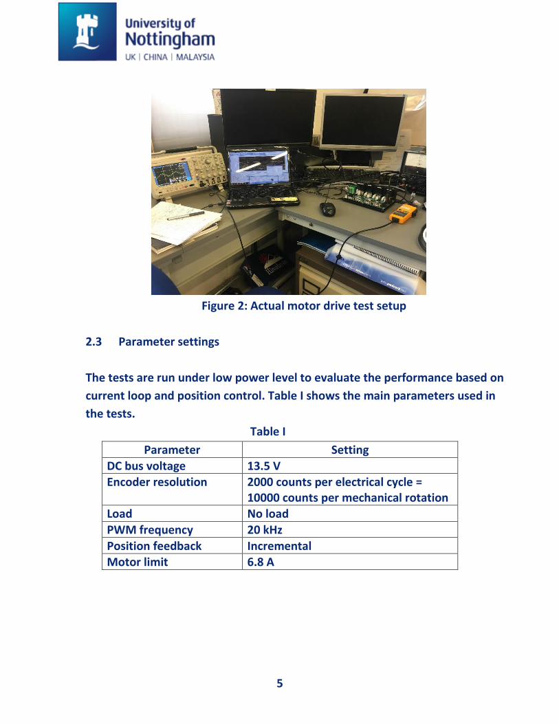
Figure 1 and 2 below show the system integration proposed for the motor
drive test.
Figure 1: System integration, interface connection
2.3 Parameter settings – follow Axis wizard – put in table as sample report
5
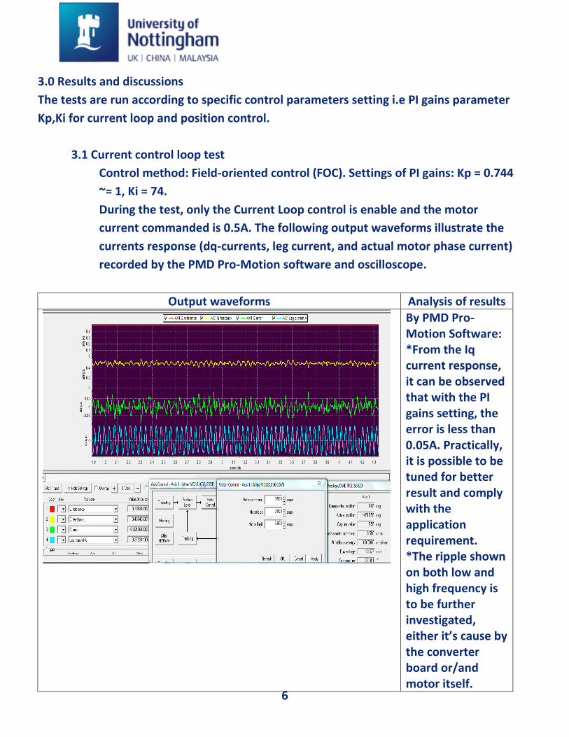
Figure 2: Actual motor drive test setup
2.3 Parameter settings
The tests are run under low power level to evaluate the performance based on
current loop and position control. Table I shows the main parameters used in
the tests.
Table I
Parameter Setting
DC bus voltage 13.5 V Encoder resolution 2000 counts per electrical cycle =
10000 counts per mechanical rotation Load No load
PWM frequency 20 kHz
Position feedback Incremental Motor limit 6.8 A
6
3.0 Results and discussions
The tests are run according to specific control parameters setting i.e PI gains parameter
Kp,Ki for current loop and position control.
3.1 Current control loop test
Control method: Field-oriented control (FOC). Settings of PI gains: Kp = 0.744
~= 1, Ki = 74.
During the test, only the Current Loop control is enable and the motor
current commanded is 0.5A. The following output waveforms illustrate the
currents response (dq-currents, leg current, and actual motor phase current)
recorded by the PMD Pro-Motion software and oscilloscope.
Output waveforms Analysis of results
By PMD Pro-Motion Software: *From the Iq current response, it can be observed that with the PI gains setting, the error is less than 0.05A. Practically, it is possible to be tuned for better result and comply with the application requirement. *The ripple shown on both low and high frequency is to be further investigated, either it’s cause by the converter board or/and motor itself.
7
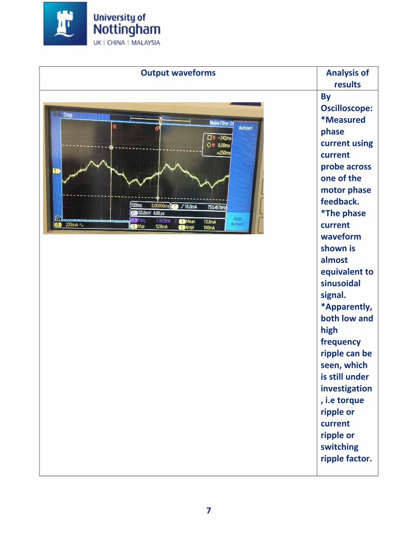
Output waveforms Analysis of results
By Oscilloscope: *Measured phase current using current probe across one of the motor phase feedback. *The phase current waveform shown is almost equivalent to sinusoidal signal. *Apparently, both low and high frequency ripple can be seen, which is still under investigation, i.e torque ripple or current ripple or switching ripple factor.

8
(Zoom in figure on ripples):
By Matlab; *Extracted data of speed during current loop control from PMD Pro-Motion software scope. *The same trend as the ripple still can be seen for both low and high frequency ripple. It may be suspected that the low frequency ripple in current is cause from the motor, while high frequency ripple is cause by the converter.
9
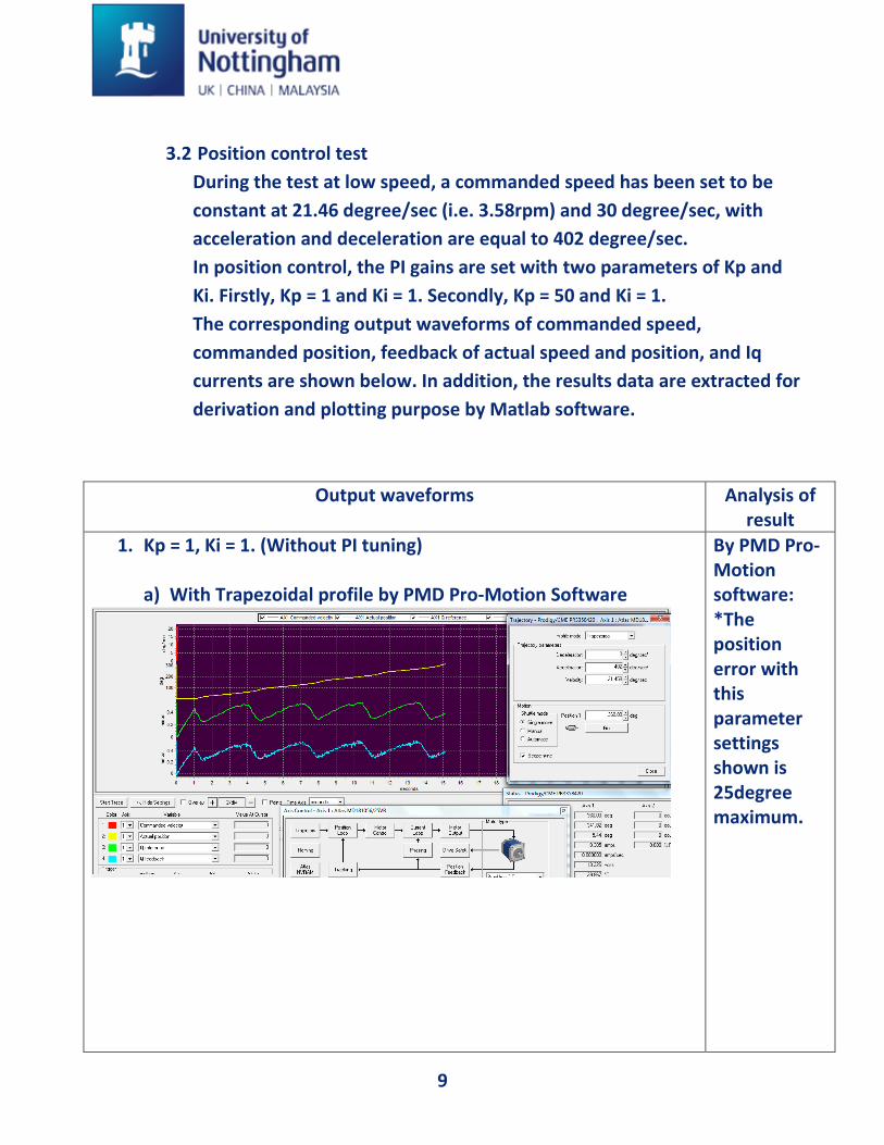
3.2 Position control test
During the test at low speed, a commanded speed has been set to be
constant at 21.46 degree/sec (i.e. 3.58rpm) and 30 degree/sec, with
acceleration and deceleration are equal to 402 degree/sec.
In position control, the PI gains are set with two parameters of Kp and
Ki. Firstly, Kp = 1 and Ki = 1. Secondly, Kp = 50 and Ki = 1.
The corresponding output waveforms of commanded speed,
commanded position, feedback of actual speed and position, and Iq
currents are shown below. In addition, the results data are extracted for
derivation and plotting purpose by Matlab software.
Output waveforms Analysis of result
1. Kp = 1, Ki = 1. (Without PI tuning) a) With Trapezoidal profile by PMD Pro-Motion Software
By PMD Pro-Motion software: *The position error with this parameter settings shown is 25degree maximum.
10
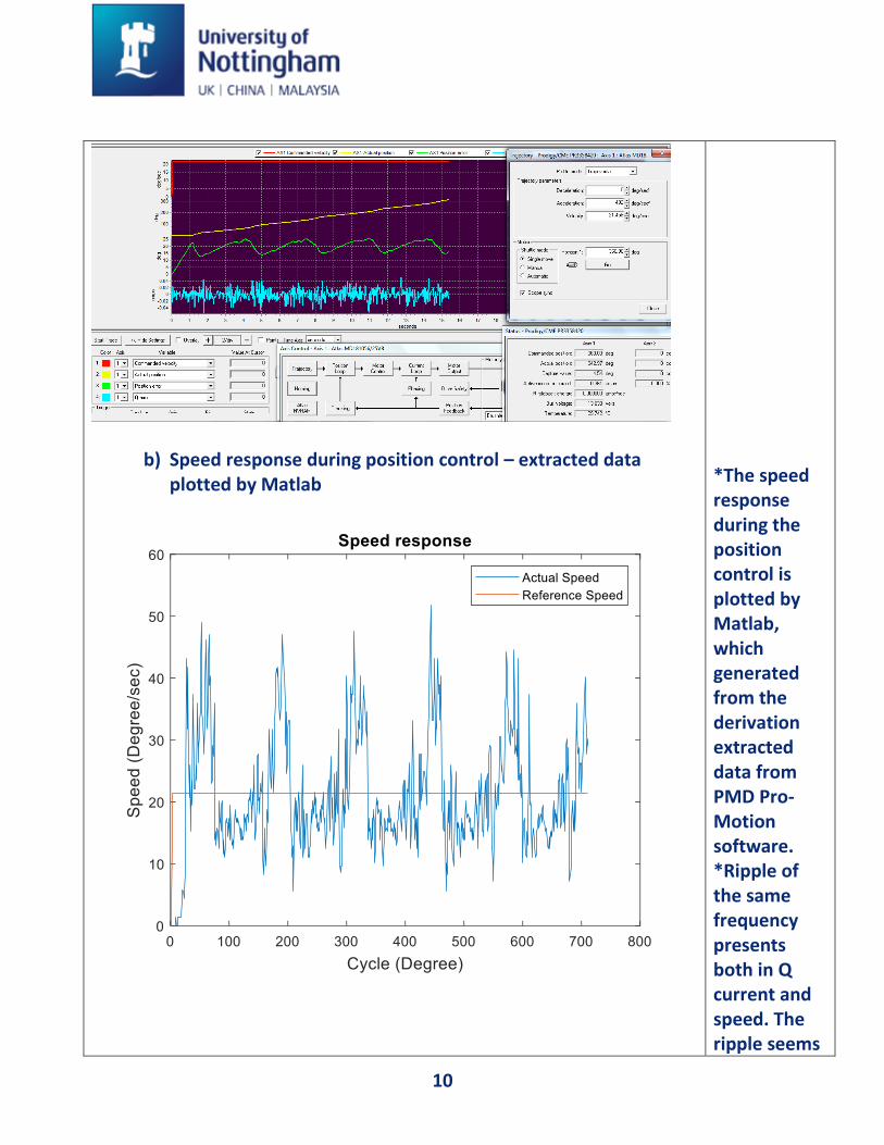
b) Speed response during position control – extracted data plotted by Matlab
*The speed response during the position control is plotted by Matlab, which generated from the derivation extracted data from PMD Pro-Motion software. *Ripple of the same frequency presents both in Q current and speed. The ripple seems
11
to be caused by the commutation of the converter.
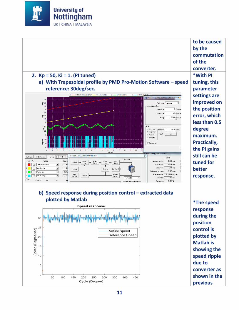
2. Kp = 50, Ki = 1. (PI tuned) a) With Trapezoidal profile by PMD Pro-Motion Software – speed
reference: 30deg/sec.
b) Speed response during position control – extracted data plotted by Matlab
*With PI tuning, this parameter settings are improved on the position error, which less than 0.5 degree maximum. Practically, the PI gains still can be tuned for better response. *The speed response during the position control is plotted by Matlab is showing the speed ripple due to converter as shown in the previous

12
(Zoom in figure on ripples);
section has been reduced since the bandwidth of the controller is higher.
13
4.0 Conclusions
According to the observation output waveforms discussed in previous section, the
PMSM is considered can be controlled by the PMD MC58420 motion controller, but
some issue should be taken into account. As known that this drive controller is
dedicated for Brushless DC, DC brush, and Stepper motors only, it provides
equivalent control method as used for PMSM i.e FOC, sinusoidal commutation, and
high performance torque control by ATLAS digital amplifier, but it is still not clear and
under investigation on how this controller can be applied for PMSM since the drive
current and Back EMF of sinusoidal are different from Brushless DC with trapezoidal.
On the other hand, it may be concluded that if the PMSM with a sinusoidal Back EMF
shape is used, this controller can be applied but the produced current / torque
response is:
• Firstly, not constant but made up from portions of a sine wave, which also lead to
ripples. This is due to its being the combination of a trapezoidal current control
strategy and of a sinusoidal Back EMF. A sinusoidal Back EMF shape motor controlled
with a sine wave strategy (three phase ON) produces a constant torque.
• Secondly, the torque value produced is weaker.
5.0 References
1. Prodigy/CME Machine-Controller Motion Control Board User’s Guide
2. Magellan Motion Control IC User’s Guide
3. Atlas Digital Amplifier Complete Technical Reference
4. Pro-Motion Software Manual User’s Guide
5. Magellan Motion Control IC Programmers Command Reference


