Vibration suppression of flexible plate structures using swarm and genetic optimization techniques by S. Julai and M. O. Tokhi reprinted from Journal of LOW FREQUENCY NOISE, VIBRATION AND ACTIVE CONTROL VOLUME 29 NUMBER 4 2010 MULTI-SCIENCE PUBLISHING COMPANY LTD.
Transcript
Vibration suppression of flexible platestructures using swarm and geneticoptimization techniques
by
S. Julai and M. O. Tokhi
reprinted from
Journal ofLOW FREQUENCY
NOISE, VIBRATION AND ACTIVE CONTROL
VOLUME 29 NUMBER 4 2010
MULTI-SCIENCE PUBLISHING COMPANY LTD.
Vibration suppression of flexible platestructures using swarm and geneticoptimization techniques
S. Julai* and M. O. TokhiDepartment of Automatic Control and Systems Engineering, The University ofSheffield, Mappin St., Sheffield S1 3ID, United Kingdom*[email protected]
Received 15th August 2010
ABSTRACTThis paper presents the development of an active vibration control mechanismusing genetic algorithm and particle swarm optimization. The approaches arerealized with single-input single-output and single-input multiple-output controlconfigurations in a flexible plate structure with all edges clamped. Simulationsare carried out with different disturbance signal types, namely random, pseudorandom binary sequence, and finite-duration step. The control design comprisesa direct minimization of the error (observed) signal by searching the optimallocations of the detector and secondary source, along with the controllerparameters. The algorithms are formulated with an objective function based onmean square of the observed vibration. In this manner, knowledge of theinput/output characterization of the system is not required for design of thecontroller. The performance of the system is assessed and analyzed both in thetime and frequency domains and it is demonstrated that the proposed schemereduces vibration of the flexible plate significantly.
1. INTRODUCTIONInterest has increased in the active control of vibration in mechanically flexiblesystems. These in aerospace and aircraft structures include space based radar antennaand solar panels, space robotics, propeller and aircraft fuselage and wings, inelectromechanical systems they include turbo generator shafts, gas turbine rotors andelectric transformer cores, and in civil engineering applications include skyscrapersand bridges [1-6]. Such structures may be damaged or become ineffective under theinfluence of undesired vibrational loads they constantly experience. Due to theseproblems, an effective control mechanism is required to attenuate the vibration levelsin order to preserve the structural integrity of such systems. The conventional formof external passive damping to change the dynamic characteristics of the structure isnot preferred as the addition of a damper adds to the overall system weight, which isundesirable and makes the system less transportable, especially for spaceapplications. This has led to extensive research into active control techniques wherethe disturbance to be cancelled or the properties of the controlled system vary withtime. Active control solutions are known to achieve good vibration suppressionperformance in comparison to passive control [7].
Active vibration control (AVC) consists of artificially generating cancellingsources to interfere destructively with the unwanted source and thus result in areduction in the level of vibration (disturbance) at desired location(s). AVC isrealized with actuators, sensors and electronic control to reduce vibration without
Vol. 29 No. 4 2010 293
JOURNAL OF LOW FREQUENCY NOISE, VIBRATION AND ACTIVE CONTROL Pages 293 – 318
necessarily adding damping to the system. Due to the broadband nature of thedisturbances, it is required that the control strategy realizes suitable frequency-dependent characteristics so that cancellation over a broad range of frequencies isachieved [8]. Remarkable advances in smart materials, such as piezoelectrictransducers which are used extensively as distributed sensors and actuators, andcomputing technology have lead AVC to provide cost-effective solutions to mostsound- and vibration-control problems [9]. However, careful consideration must begiven to positioning the sensors and actuators to ensure good control andmeasurement, misplaced sensors and actuators will result in observability andcontrollability problems [10]. This means that the locations of these transducershave significant influence on the performance of the control system as well as thecontrolled response. Many techniques have been reported on finding optimallocations of sensors and actuators [11-15]. Han and Lee, 1999 [11], have usedgenetic algorithms (GA) to find suitable locations of piezoelectric sensors andactuators of a cantilevered composite plate with considerations of controllability,observability and spillover prevention. Significant vibration reduction for the firstthree modes (controlled modes) has been achieved using the coupled positiveposition feedback in the vibration control experiment. In [12], they have presenteda numerical scheme using GA to find the optimal locations for the sensors andactuators in vibration control of a flexible plate, where the chromosome has beenpresented as the binary encoded string for the node index. Due to the difficultiesencountered during the decoding process of the objective function when handlingmultimodal functions, Hongwei et al. [13] have proposed the optimal control offlexible smart structures bonded with piezoelectric actuators and sensors using float-encoded genetic algorithms to determine the location of actuator and sensor andfeedback gains. The performance function was based on the maximization ofdissipation energy due to a control action. Other approaches to find optimal positionof the sensors and actuators using particle swarm optimization (PSO) are reportedin [14-15]. In [14], Rao et al. have used PSO to determine optimal placement ofpiezoelectric patch actuators and accelerometer sensors alongside an H∞ basedcontroller to suppress the first three modes of vibration in a composite fin-tip withsurface bonded piezoelectric actuators and accelerometer sensors. Montazeri et al.[15] have utilized PSO to find the number, position and size of PZT sensors andactuators for active noise and vibration control of a simply supported laminated thinplate. They have used the Hankel singular values of the state-space model of thesystem as the cost function to obtain the positions such that the closed-loop systemis able to damp the maximum number of modes with an acceptable control effortand minimum complexity of the control system. All the researches above haveshown the importance of optimal placement of sensor and actuator to achieve asignificant level of vibration suppression. Hence, in the application of AVC systems,it is desirable to optimally utilize the actuators and sensors by partly covering thehost structure with patches of active material with the best actuator and sensorlocations.
Implementation of AVC on flexible plates is carried out in this work. The plateis characterized by a number of natural frequencies within the control anddisturbance bandwidth, and hence, can easily be subjected to parameteruncertainties and variations, high-order dynamics or nonlinearity and externaldisturbances. Model-based AVC approaches have been reported in [16-18] usinggenetic optimization approaches. In this work, a non-model based approach isdeveloped where the controller is designed directly based on minimization of theobserved signal or ‘uncontrolled deflection’ using GA and PSO. The approach doesnot require knowledge of the input/output characterization of the system forcontroller design. These algorithms are nature-inspired with population-basedstochastic search and have been very popular in the field of computationalintelligence. Solving optimization problems using stochastic search can often out-perform classical methods of optimization when applied to difficult real-worldproblems. They offer better chances to achieve the global optima since they do not
Vibration suppression of flexible plate structures using swarm and geneticoptimization techniques
JOURNAL OF LOW FREQUENCY NOISE, VIBRATION AND ACTIVE CONTROL294
use gradient information and are very useful in solving problems where suchinformation is unavailable or very costly to obtain [19]. Classical methods based ongradient information, on the other hand, emphasize accurate and exact computation,but may fail to achieve the global optimum.
The rest of the paper is structured as follows: Section 2 presents classicalgoverning dynamic equations of a thin rectangular plate and the correspondingnumerical simulation algorithm based on the finite difference (FD) method. The GAand PSO algorithms are described in Section 3. The AVC strategies are presented inSection 4. Section 5 presents performance results of the AVC approaches within theflexible plate simulation environment. The results are analyzed and discussed fromthe time- and frequency-domain perspectives. The paper is concluded in Section 6.
2. THE FLEXIBLE PLATE STRUCTUREDynamic modelling and simulation of a flexible plate structure using the FD methodhas been reported in [20], where a flat, square plate with all edges clamped has beenconsidered. The classical dynamic equation of a thin rectangular plate is describedwith a partial differential equation (PDE) formulation as [21, 22]:
(1)
where w is the lateral deflection, r is the mass density per unit area, q = q(x,y) is thetransverse external force at point (x, y) on the plate and has dimensions of force perunit area, ∂2w/∂t2. is the lateral acceleration, D = [Eh3 / 12(1 – u)] is the flexturalrigidity with u representing the Poisson ratio, h the thickness of the plate, and E theYoung’s modulus. A simulation algorithm characterizing the dynamic behaviour ofthe plate is developed through discretisation of the PDE. The plate can be dividedinto n×m sections, along the x and y axes as x = i∆x and y = j∆y. Using a centraldifference approximation for the first-, second-, third- and fourth-order derivativesof the response, a linear relation for the deflection of each section (mesh) can bedeveloped using FD approximations, as
(2)
where the x-axis is represented with the reference index i, y-axis with the referenceindex j, and time, t represented with a reference index k. Here, ,wi,j,k+1. is thedeflection of nodal point (xi , yj) of the plate at time step k + 1. For the case of alledges clamped, the deflection is always zero along the edges, and the tangent of thedeflection at the edge is equal to zero, e.g. at y = a, w�y=a = ∂w/∂y�y=a = 0. Thiscondition needs to be satisfied at every nodal point along the clamped edge withinthe FD formulation [20].
The plate is divided into 20×20 sections with a sampling time of 0.0016 sec. Analuminium type plate with boundary condition of all edges clamped andspecifications given in Table I is considered. The simulation algorithm developed isused as a platform for test and performance evaluation of AVC approachesdeveloped in this work.
12
,i jw+ + ++ − + − − + −+ + + 1 1 1 1 1 1 1, , , , , , ,k i j k i j k i j k
w w w
+ + + ++ + − −w w w wi j k i j k i j k i j2 2 2 2, , , , , , , ,kk i j k i j k
i jw wt q) + − +−2
1
2
, , , ,
,∆
ρ
wD t
w w wi j k
xy
i j k i j k i j, , , , , , ,+ + += − + ( +1
2
4 120 8
∆∆ρ
11 1 1, , , , ,k i j k i j k
w w+ + − −
∂∂
+∂
∂ ∂+
∂∂
+∂∂
=4
4
4
2 2
4
4
2
22
w
x
w
x y
w
y D
w
t
q
D
ρ
Vol. 29 No. 4 2009
S. Julai and M. O. Tokhi
295
Table IParameters of the flexible plate structure.
3. OPTIMIZATION TECHNIQUESIn this section, GA and PSO used for minimizing the objective function are brieflydiscussed here. Although both algorithms are population-based, the conceptualbases of these two algorithms rest upon two completely different philosophies: PSOis based upon social swarm behaviour, and GA is based upon genetic encoding andnatural selection. Further description of both algorithms is given below.
3.1 Real-coded genetic algorithmGA was introduced by John Holland [23] based on the principle of CharlesDarwinian Theory of evolution to natural biology. It is a search procedure based onthe mechanics of natural selection and natural genetics. In traditional GA, all thevariables of interest must first be encoded as binary digits (genes) forming a string(chromosome).This representation is known as binary-coded genetic algorithm(BCGA). Each chromosome (individual) has an associated fitness which is the valueof the objective function for that set of parameters and contains sub-strings or genesas units that contribute in different ways to the overall fitness of the individual.BCGA is found to be a robust search technique avoiding local optima, but the majordrawback is the difficulty faced when it is applied to problems with large searchspace and requiring high precision. Large string lengths result in more precisesolutions but lead to an increase in computational cost [24]. To overcome thedifficulties related to binary representation, a floating-point representation ofparameters as chromosomes known as real-coded genetic algorithm (RCGA) isused. All genes in a chromosome used in RCGA are real numbers. The use of thisfloating point representation outperforms binary representations in real-valuedoptimization problems because they are more consistent, precise, and lead to fasterconvergence [25]. In RCGA, the length of chromosomes becomes shorter than thosewith the equivalent binary representation. This implies that computer programmingfor such algorithms can be easily performed. The tuning mechanism for mutationand crossover operations is also performed using floating point numbers instead oflong strings of zeros and ones. In RCGA, three basic operations are used: selection,crossover, and mutation.
(i) SelectionSelection is an important aspect of evolutionary computation. It dictates whatmember of the current population affects the next population. More fit individualsare generally given a higher chance to participate in the recombination process.Stochastic universal sampling (SUS) provides zero bias and minimum spread. Theindividuals are mapped to contiguous segments of a line, such that each individual’ssegment is equal in size to its fitness exactly as in roulette-wheel selection. Hereequally spaced pointers are placed over the line as many as there are individuals tobe selected [26]. After the selection, the parent chromosomes are combined andmutated to form the offspring chromosomes.
Vibration suppression of flexible plate structures using swarm and geneticoptimization techniques
JOURNAL OF LOW FREQUENCY NOISE, VIBRATION AND ACTIVE CONTROL296
(ii) CrossoverLet x = (x1,....,xn) and y = (y1,....,yn) be the parent strings, where the generic xi andyi are real variables. In extended intermediate recombination
(3)
where ak is chosen uniform randomly in the interval [–0.25,1.25]. Intermediaterecombination is capable of producing any point within a hypercube slightly largerthan that defined by the parents. Fig. 1 (a) shows the possible area of offspring afterintermediate recombination.
(iii) MutationThis function takes a vector containing the real representation of the individuals inthe current population, mutates the individuals with probability pm and returns theresulting population. The mutation operator is able to generate most points in thehypercube defined by the variables of the individual and the range of the mutation,as in Fig. 1 (b).
Figure 1. (a) Possible areas of the offspring after intermediate recombination, and (b) effect of mutation.
3.2 Particle swarm optimizationParticle swarm optimization shares many similarities with evolutionarycomputational techniques such as GA. PSO was developed by Eberhart andKennedy [27] in 1995, inspired by the ability of flocks of birds, schools of fish, andherds of animals to adapt to their environment, find rich sources of food byimplementing an information-sharing approach, and it possesses the properties ofeasy implementation and fast convergence [27, 28]. The algorithm has been widelyapplied to continuous and discrete optimization problems and has received greatattention in systems and control engineering, automatic recognition, radio systems,etc. Starting with a randomly initialized population, each particle in the PSO fliesthrough the d-dimensional problem space and remembers the best position it hasseen. The particles evaluate their positions relative to a global fitness during eachiteration and use their memorised best positions to adjust their own velocities andsubsequent positions. In this way, the particles tend to fly towards better and bettersearching areas through the search process.
In a PSO algorithm, the position vector and the velocity vector of the i-th particlein a d-dimensional search space can be represented as Xi = (xi1, xi2,...,xid) and Vi =(vi1, vi2,...,vid), respectively. The best position of each particle (which corresponds tothe best fitness value obtained by that particle at time t) is denoted as Pi (pi1,pi2,...,pid), and the fittest particle found so far at time t as Pg (pg1, pg2,...,pgd). Thenthe new velocities and positions of the particles for the next fitness evaluation arecalculated using the following equations:
(4)×2
Rannd( ) ( ( ))• × −p x tgd id
v t v t c p x t cid id id id
( ) ( ) ( ) ( ( ))+ = × + × • × − +11 2
ω rand
k n= 1 ,....,z x y xk k k k k
= + −α ( )
Vol. 29 No. 4 2009
S. Julai and M. O. Tokhi
297
(5)
where w is the inertia weight, c1 is the cognition factor, c2 is the social factor, andrand (•) and Rand (•) are two separately generated uniformly distributed randomnumbers in the range [0, 1] [29].
Abd Latiff and Tokhi, [30] have proposed a strategy to guarantee fastconvergence as an improvement to the concept of time-varying accelerationcoefficients (TVAC), developed by Ratnaweera et al., [31], to effectively control theglobal search and convergence to the global best solution. They have establishedthat by continuously modifying the value of inertia weight, superior results can beachieved as compared to the case when the inertia weight is fixed. For fastconvergence purposes, the particles have to know their location and relative distancefrom each other in exploring the search space. To do so, the spread factor (SF) hasbeen introduced, which measures the distribution of particles in the search space aswell as the precision and accuracy of the particles with respect to the globaloptimum. Precision (or spread of particles in the search space) refers to themaximum distance between particles in the best and worst positions while accuracy(or deviation of the particles) refers to the distance of average particle position fromthe global best particle. The value of spread factor varies from the maximum rangeof the search space down to the desired convergence precision and can be calculatedas
(6)
where spreadid = xmaxid – xminid and deviationid = ∑(xid – gbestid)/N, with , xmaxid andxminid representing maximum and minimum values of the ith particle’s position, N isthe number of particles, and rangemax and rangemin. are maximum and minimumrange of the specified variables. This factor is used to modify the inertia weight,
(7)
with(8)
where c1 is linearly reduced to zero from its initial value of 2, and c2 is maintainedat 2 to ensure all particles are pulled towards global optimum.
4. ACTIVE VIBRATION CONTROL DESIGN4.1 SISO-AVCA schematic diagram of the geometric arrangement of a single-input single-output(SISO) feedforward AVC structure considered in this study is shown in Fig. 2 (a).UD and UC are the disturbance and secondary signals at the source locations whereasUM and Y are the detected and observed signals, respectively. The aim of thecontroller design is to minimize the deflection Y via UC by generating an anti-phasecontrol signal to counteract the vibration produced by UD [32]. The controller isrealized in a linear parametric form as
(9)
where ai, bj are the controller parameters n≥m and represent the order of the
U t b U t j a U t iC j M
j
m
i Ci
n
( ) ( ) ( )= ⋅ − − ⋅ −= =
∑ ∑0 1
c / _iter
c
iter1
2
2 1
2
= × −=
( max )
ω = − ×exp( ( max ))iter / SF _iter
SFspread deviation
range rangeidid id= ×
+−
0 5.
max min
x t x t v tid id id
( ) ( ) ( )+ = + +1 1
Vibration suppression of flexible plate structures using swarm and geneticoptimization techniques
JOURNAL OF LOW FREQUENCY NOISE, VIBRATION AND ACTIVE CONTROL298
controller. The number of parameters to be estimated is n + m + 1. In this work,randomly selected controller parameters, i.e. a1,...,an and b0,...,bm are identified fordifferent, arbitrarily chosen orders to fit to the system. The stability of the obtainedcontroller must be ensured. In the discrete-time case, pole-zero diagram of thecorresponding controller transfer function provides a simple and effective means ofassessing its stability. Using equation (9), the transfer function of the controller canbe formed as
(10)
Optimization techniques are carried out to achieve vibration reduction by feedingthe observed signal Y to the controller C via optimization routines. The optimizationprocess is based on minimizing the mean-squared error (MSE) of the observedsignal, Y. This is formulated as:
; subject to –1 ≤ ai ≤ 1 and –1 ≤ bi ≤ 1 (11)
where S represents the number samples.
Figure 2. AVC structure for flexible plate: (a) SISO-AVC, and (b) SIMO-AVC.
4.2 SIMO-AVCThe SIMO-AVC structure for the flexible plate is illustrated in Fig. 2 (b). Thecontroller is designed to minimize the deflection Y, where Y = [y1, y2,...,yk], via UCby generating anti-phase control signal to counteract the vibration produced by UD.For the case where the number of observation points is set to k, the control signalsare given as
(12)
where p =1, 2,…, k. In this case, the number of parameters to be estimated is (n +m + 1) × k. The transfer function of controller path p can be formed as in equation(10). The performance of the SIMO-AVC system can be assessed with the MSE ofthe observed signals Y. The objective function is thus given as
;
subject to –1 ≤ ai ≤ 1 and –1 ≤ bi ≤ 1 (13)
fS
Y i Y i Y iSISO k
i
S
error ( )( ) ( ) ... ( )= + + +( )
=∑1
1 2
2
1
U t b U t j a U t iCp jp M
j
m
ip Cpi
n
( ) ( ) ( )= ⋅ − − ⋅ −= =
∑ ∑0 1
fS
Y ierror
i
S
( )( )
SISO= ( )
=∑1 2
1
C zb b z b z b z
a z a zm
m
( )...
...=
+ + + ++ + + +
− − −
− −0 1
12
2
11
221 aa z
nn−
Vol. 29 No. 4 2009
S. Julai and M. O. Tokhi
299
4.3 System geometryThe effectiveness of AVC for controlling the vibration of a flexible structure isdirectly affected by the geometrical arrangement of system components: detection,observation and secondary source points. A typical implementation comprises asensor, to detect the vibration to be suppressed, and control electronics drivingactuators to generate cancelling sources to interfere destructively with the unwantedsignal from the primary point. To control the vibration on the structure requires thatthe actuators are optimally situated. In this work, two mechanisms of geometricalarrangement for detection and secondary source points are investigated, i.e. variablegeometry and fixed geometry. For both mechanisms, points of primary andobservation for both cases are kept at specific mesh-points.
4.3.1 Variable geometryIn this mechanism, the locations for the detection and secondary source points aswell as the parameters of the controller are determined by GA/PSO. Since thealgorithms use stochastic random searches, there are a few possibilities that need tobe considered. The algorithms may converge to the same point for any of thesearched points the same coordinate as any fixed points, i.e. primary, observation 1(SISO/SIMO case) and observation 2 (SIMO case) points. Also, in SIMO case,secondary source point 1 might be the same as secondary source point 2, causingboth elements to act as one secondary source, resembling SISO-AVC. Therefore,penalty has to be added to the algorithms to ensure that such possibilities can beavoided. On the other hand, collocation of the detection point with its correspondingsecondary source point is allowable. This may happen when the location ofdetection point is the same as the secondary point 1 or secondary source point 2either in SISO or SIMO case. The advantage of collocation is in terms of reductionof the required space to install actuator and sensor in the mechanical design of thesystems [33].
Given that the plate is divided into 20 × 20 sections and the deflection along theboundaries is zero, the range of coordinates for the detection and secondary sourcepoints must be within 1 and 19, as in Figure 3, where the shaded area represents theregion over which the deflection is either zero or almost zero. Hence, about 19 × 19possible detection and secondary source locations are to be explored to achieve thehighest degree of effectiveness to produce the lowest value of the objective function.The execution of the RCGA-AVC and PSO-SF-AVC of the flexible plate aredescribed as below:
Figure 3. Predefined region of arrangement for systems components.
(i) RCGA-AVCstep 1 Initialize parameters of the flexible plate and location of disturbance
and observation points: excitation point, P = (7,7), observation point1, O1 = (11,12) for SISO and SIMO cases, and observation point 2,O2 = (13,8) for SIMO case only.
Vibration suppression of flexible plate structures using swarm and geneticoptimization techniques
JOURNAL OF LOW FREQUENCY NOISE, VIBRATION AND ACTIVE CONTROL300
step 2 Select types of disturbance signal, i.e. random, PRBS or finite-durationstep signal.
step 3 Initialize range of variables for optimal location of detection andsecondary source points, in the range [1, 19], and range of variables forcontroller parameters, in the range [-1, 1].
step 4 Generate random population of X chromosomes where the initialchromosome for ith individual is represented as below:
SISO case:
(14)
where the first four variables are coordinates for detection point, D = (di(1), di(2)) andsecondary source point, S = (si(3), si(4)). The remaining variables are the controllerparameters to form transfer functions as in equation (10).
SIMO case:
(15)
where the first six variables are coordinates for detection point, D = (di(1), di(2)),secondary source point 1, S1 = (si(3), si(4)), and secondary source point 2, S2 = (si(5), si(6)).The remaining variables are the controller parameters to form transfer functions as inequation (10).
step 5 Add penalty to Xi as follows:
(16)
(17)
step 6 Evaluate the fitness value, i.e. MSE of the observed signal, for eachchromosome in the population according to equations (11) or (13).
step 7 Create a new population by repeating the following steps until the newpopulation is complete:7.1. In selection operator, select two parent chromosomes from a
population using SUS algorithm, according to their fitness.Parents that produced the smallest MSE value are considered asthe best fit individuals.
7.2. In crossover operator, cross over the parents to form a newoffspring (children) according to equation (3). If no crossover wasperformed, offspring is an exact copy of parents.
7.3. In mutation operator, mutate the new offspring to alter the genes ofsome of the children, according to the probability of mutation, pm.
si 3
if (( )
,, ) ( , ) ( ,( ) ( ) ( ) ( ) (
or or s P s s O s si i i i i4 3 4 1 3
= =44 2)
) = O
or
SIMO case only
( , )( ) ( )
s s Si i3 4 2
=� �������� �������
otherwise
S
s si i
1
3 4
penalty
=
+( , ) ,( ) ( )
( , ),( ) ( )
s si i3 4
di
if (( )1
,, ) ; ( , ) ( ,( ) ( ) ( ) ( )
or ; or d P d d O d di i i i2 1 2 1 1
= =ii
O( )
)2 2
=
otherwiseD
d di i
penalty
=+( , ) ,
( ) ( )1 2
i id d
( ) ( )( , ),
1 2
Xi i i i i i i i
d d s s s s a= ( , , , , , , ,( ) ( ) ( ) ( ) ( ) ( ) ( )1 2 3 4 5 6 7
…,, , , , )( ) ( ) (( ) )
a b bi n k i n k i n m k× + × + + × +6 7 7
…
Xi i i i i i i n i
d d s s a a b= +( , , , , , , ,( ) ( ) ( ) ( ) ( ) ( ) (1 2 3 4 5 4
…nn i n m
b+ + +5 5) ( ), , )…
Vol. 29 No. 4 2009
S. Julai and M. O. Tokhi
301
step 8 Add penalty to the offspring as in step 5.step 9 Evaluate the fitness values of all offspring.step 10 Reinsert the offspring into the original population using fitness-based-
reinsertion, with the new offspring replaced with the least fit member ofthe original population.
step 11 If the maximum generation is not reached repeat step 7 untilconvergence, else, the algorithm is ended.
step 12 Output the values of the decision variables for final evaluation of theAVC system. End of procedure.
(ii) PSO-SF-AVCstep 1-3 Same as in RCGA-AVC procedures.step 4 Initialize the population of particles with random positions and
velocities, and maximum iteration, where the initial position vector forith particle is represented as in step 4 in RCGA-AVC procedure.
step 5 Same as in RCGA-AVC procedure.step 6 Evaluate the fitness value, i.e. MSE of the observed signal, for each
particle of the population according to equations (11) or (13). The bestparticle that produces the smallest fitness value with its position will bestored as global best position.
step 7 Calculate spread, deviation, SF and ω, as in equations (6), (7), and (8),for all the variables and particles.
step 8 Update the position and velocity of particle according to equations (4)and (5).
step 9 Add penalty to the updated position as in step 5.step 10 Evaluate the fitness values of all particles and determine the best
particle of the current population. If the fitness value of the MSEobserved signal is smaller than the fitness value of the global bestposition, then update the global best position and its fitness value withthe position and fitness value of the current best particle.
step 11 If the maximum generation is not reached repeat step 7 untilconvergence, else, the algorithm is ended.
step 12 Output the global best position for final evaluation of the AVC system.End of procedure.
4.3.2 Fixed geometryFor the case of fixed geometry, the locations of detection and secondary sourcepoints are fixed. This can be done after variable-geometry-mechanism has beencarried out for all the algorithms for both SISO and SIMO cases. Since all thealgorithms are stochastic search, the solutions obtained are different from oneanother, giving more than one possible location for each of the search points.Therefore, in order to choose the best locations, the levels of attenuation for all casesusing different algorithms are compared and the searched points that give themaximum mean of the attenuations for the first five dominant vibration modes areused for all types of primary sources. Here, the optimization process is carried outon the parameters of the controller so as to minimize the objective function
5. IMPLEMENTATION AND RESULTSThis section presents the performances of the SISO- and SIMO-AVC systems withRCGA and PSO-SF design approaches. The disturbance signals, i.e. random, PRBS,and finite-duration step signals, were applied to the plate at t = 0.2 to t = 0.5 sec. Forthe detection and secondary source points within the predefined range, and with thedisturbance types, it was observed that the first five dominant modes of the platewere at 10.35 rad/sec, 33.76 rad/sec, 64.94 rad/sec, 81.88 rad/sec, and 99.37 rad/sec.The results presented in this section are assessed on a comparative basis in terms ofspectral density attenuation for both cases of variable-geometry-AVC and fixed-geometry-AVC with RCGA-, and PSO-SF-optimization techniques.
Vibration suppression of flexible plate structures using swarm and geneticoptimization techniques
JOURNAL OF LOW FREQUENCY NOISE, VIBRATION AND ACTIVE CONTROL302
5.1 SISO-AVC5.1.1 Variable-geometry A simulation environment was developed using MATLAB software. The simulationwas carried out to find the optimal points of detection and secondary sourcelocations together with controller parameters. As shown in Fig. 4, the best(minimum) MSE levels obtained with a random signal using RCGA-AVC and PSO-SF-AVC, were 1.42 × 10⁻¹⁴ and 8.04 × 10⁻¹⁵, respectively. The best MSE levelachieved with PRBS as the disturbance signal were 3.49 × 10⁻¹⁶ and 7.89 × 10⁻¹⁶
using RCGA-AVC and PSO-SF-AVC, respectively. For finite-duration step signal,the MSE level at the maximum iteration were 6.47 × 10⁻¹⁴ and 3.77 × 10⁻¹⁴.
Since the algorithms are of stochastic nature where the solutions found may varyeach time, investigations were carried out to check its stability by running theprogram 10 times with the corresponding best parameters for each algorithm. Theresults tabulated in Table II are based on statistical performance, i.e. minimum,maximum, mean, and standard deviation of the objection function as in equation(II). The smallest MSE value with random, PRBS, and finite-duration step signalswere obtained using PSO-SF-AVC, RCGA-AVC, and PSO-SF-AVC, respectively. Itis noted from the maximum, mean, and standard deviation values that all algorithmshave performed consistently similary with various signal types.
It is observed from Fig. 4 that the MSE convergence for all algorithms began at aconsiderable large number for iterations less than 5. Rapid convergence was reached inthe first 10 iterations, where the algorithms tried to locate the optimum region fordetection and secondary source(s) points. No or minor improvement was achieved after30 iterations. This represents that 40 iterations are reasonable and enough to obtain bothoptimum locations and controller parameters for flexible plate-AVC-system.
Figure 4. Convergence graph for variable-geometry SISO-AVC: (a) random, (b) PRBS, and (c) finite-duration step disturbance.
Since computational time is one of the important factors to be considered in anoptimization process, investigations on the number of individuals/particles werecarried out by varying those numbers from 5 to 40. Fewer individuals/particlesresulted in high values of MSE but faster computational time, while a high numberof individuals/particles resulted in smaller values of MSE with very slow executiontime. In order to get compromise values between MSE and computational time, thebest number of individuals/particles was found to be 20 for all algorithms. As shownin Fig. 5, the computational time for RCGA was significantly lower than PSO-SFmechanisms.
Vol. 29 No. 4 2009
S. Julai and M. O. Tokhi
303
Figure 5. Computational time for random-SISO-AVC with RCGA and PSO-SF.
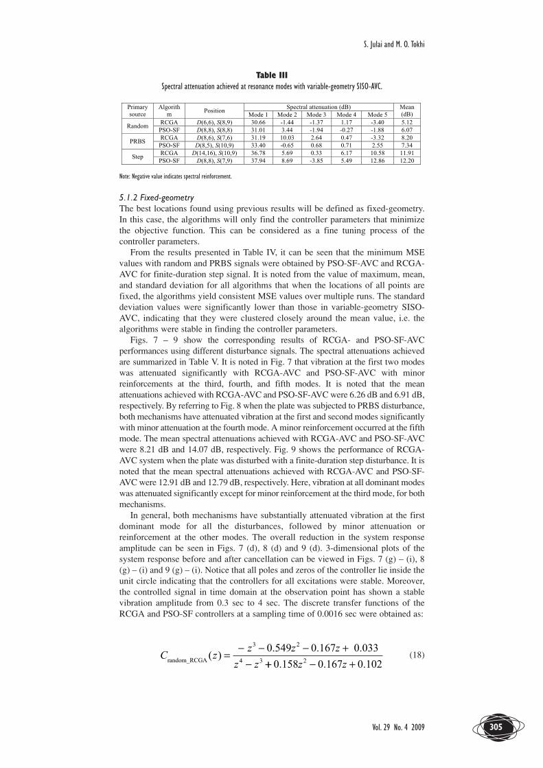
Fig. 6 shows the performance results of RCGA-AVC and PSO-SF-AVC withdifferent disturbance signals. For RCGA-AVC, a generation gap of 0.80 and amutation rate of 0.12 were used. The best model order for the controller thatproduced the smallest MSE level was 4 for both mechanisms. It can be seen thatboth mechanisms successfully attenuated the first mode significantly, followed byminor attenuations and minor reinforcement at the remaining modes. The spectralattenuations for each mode, with the corresponding locations of detection andsecondary source points are listed in Table III.
As summarized in Table III, the maximum mean attenuations achieved withrandom, PRBS, and finite-duration step signals were achieved using PSO-SF-AVC(mean: 6.07 dB, best location: D(8,8), S(8,8)), RCGA-AVC (mean: 8.20 dB, bestlocation: D(8,6), S(7,6)), and PSO-SF-AVC (mean: 12.20 dB, best location: D(8,8),S(7,9)), respectively. These six locations were nearer, or next to the primary source.The distance between the primary source and the detection point is shorter, enablingthe sensor to detect most of the dynamic characteristics of the disturbance signalsfor control purposes. The actuator, located at the secondary source point, acted as acontroller to generate a cancelling source to interfere destructively with theunwanted source and thus result in a reduction in the level of vibration. The shorterdistance between primary and secondary source results in a shorter travelling pathbetween cancelling and unwanted sources, thus enhancing the performance ofvibration suppression. In this case, the physical extent of vibration cancellationaround the observation point is higher when the detection and secondary sourcepoints are located nearer to the primary source.
Figure 6. Performance of RCGA-AVC and PSO-SF-AVC: (a) random-spectral density of response, (b) PRBS-spectral density of response, and (c) finite-duration step-spectral density of response.
Table IIMSE value for 10 trials for variable-geometry SISO-AVC.
Vibration suppression of flexible plate structures using swarm and geneticoptimization techniques
JOURNAL OF LOW FREQUENCY NOISE, VIBRATION AND ACTIVE CONTROL304
Table IIISpectral attenuation achieved at resonance modes with variable-geometry SISO-AVC.
Note: Negative value indicates spectral reinforcement.
5.1.2 Fixed-geometry The best locations found using previous results will be defined as fixed-geometry.In this case, the algorithms will only find the controller parameters that minimizethe objective function. This can be considered as a fine tuning process of thecontroller parameters.
From the results presented in Table IV, it can be seen that the minimum MSEvalues with random and PRBS signals were obtained by PSO-SF-AVC and RCGA-AVC for finite-duration step signal. It is noted from the value of maximum, mean,and standard deviation for all algorithms that when the locations of all points arefixed, the algorithms yield consistent MSE values over multiple runs. The standarddeviation values were significantly lower than those in variable-geometry SISO-AVC, indicating that they were clustered closely around the mean value, i.e. thealgorithms were stable in finding the controller parameters.
Figs. 7 – 9 show the corresponding results of RCGA- and PSO-SF-AVCperformances using different disturbance signals. The spectral attenuations achievedare summarized in Table V. It is noted in Fig. 7 that vibration at the first two modeswas attenuated significantly with RCGA-AVC and PSO-SF-AVC with minorreinforcements at the third, fourth, and fifth modes. It is noted that the meanattenuations achieved with RCGA-AVC and PSO-SF-AVC were 6.26 dB and 6.91 dB,respectively. By referring to Fig. 8 when the plate was subjected to PRBS disturbance,both mechanisms have attenuated vibration at the first and second modes significantlywith minor attenuation at the fourth mode. A minor reinforcement occurred at the fifthmode. The mean spectral attenuations achieved with RCGA-AVC and PSO-SF-AVCwere 8.21 dB and 14.07 dB, respectively. Fig. 9 shows the performance of RCGA-AVC system when the plate was disturbed with a finite-duration step disturbance. It isnoted that the mean spectral attenuations achieved with RCGA-AVC and PSO-SF-AVC were 12.91 dB and 12.79 dB, respectively. Here, vibration at all dominant modeswas attenuated significantly except for minor reinforcement at the third mode, for bothmechanisms.
In general, both mechanisms have substantially attenuated vibration at the firstdominant mode for all the disturbances, followed by minor attenuation orreinforcement at the other modes. The overall reduction in the system responseamplitude can be seen in Figs. 7 (d), 8 (d) and 9 (d). 3-dimensional plots of thesystem response before and after cancellation can be viewed in Figs. 7 (g) – (i), 8(g) – (i) and 9 (g) – (i). Notice that all poles and zeros of the controller lie inside theunit circle indicating that the controllers for all excitations were stable. Moreover,the controlled signal in time domain at the observation point has shown a stablevibration amplitude from 0.3 sec to 4 sec. The discrete transfer functions of theRCGA and PSO-SF controllers at a sampling time of 0.0016 sec were obtained as:
(18)C zz z z
z zrandom_RCGA 4 3
0.549 0.167 0.033( ) =
− − − +−
3 2
++ − +0.158 0.167 0.1022z z
Vol. 29 No. 4 2009
S. Julai and M. O. Tokhi
305
(19)
(20)
(21)
(22)
(23)
Table IVMSE value for 10 trials for fixed-geometry SISO-AVC.
Table VSpectral attenuation achieved at resonance modes with fixed-geometry SISO-AVC.
Note: Negative value indicates spectral reinforcement.
C zz . z . z .
z .step_PSOSF( ) =
− − − −−
3 2
4
0 063 0 225 0 737
0 7199 0 198 0 563 0 0163 2z . z . z .+ + −
C zz z z
zPRBS_PSOSF( )
. . .
.=
− + + −+
3 2
4
0 385 0 537 0 017
0 675zz z z3 20 546 0 474 0 168+ + −. . .
C zz . z . z .
z .random_PSOSF( ) =
− − + −−
3 2
4
0 189 0 592 0 087
0 8825 0 139 0 101 0 4013 2z . z . z .+ + −
C zz z z
zstep_RCGA( )
0.529 0.015 0.101 0.415
0=
− + + −+
3 2
4 ..512 0.069 0.021 0.028z z z3 2− + −
C zz z z
zprbs_RCGA
3 2
( )0.588 0.304 0.155 0.072
0.=
− − ++4 4452 0.227 0.065 0.283z z z3 2− − +
Vibration suppression of flexible plate structures using swarm and geneticoptimization techniques
JOURNAL OF LOW FREQUENCY NOISE, VIBRATION AND ACTIVE CONTROL306
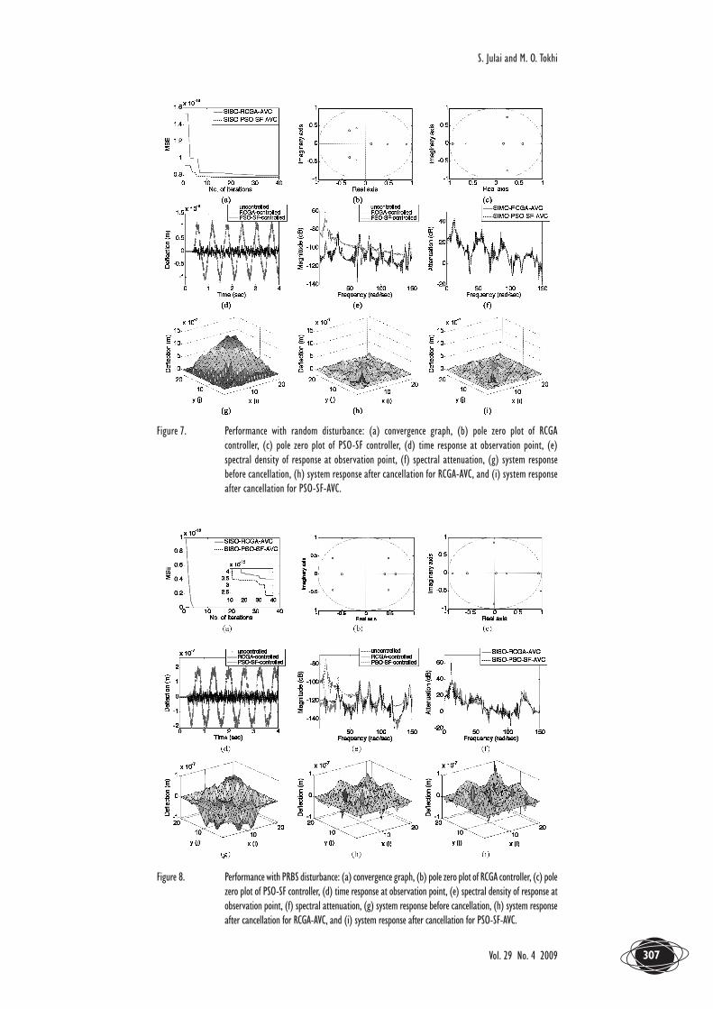
Figure 7. Performance with random disturbance: (a) convergence graph, (b) pole zero plot of RCGAcontroller, (c) pole zero plot of PSO-SF controller, (d) time response at observation point, (e)spectral density of response at observation point, (f) spectral attenuation, (g) system responsebefore cancellation, (h) system response after cancellation for RCGA-AVC, and (i) system responseafter cancellation for PSO-SF-AVC.
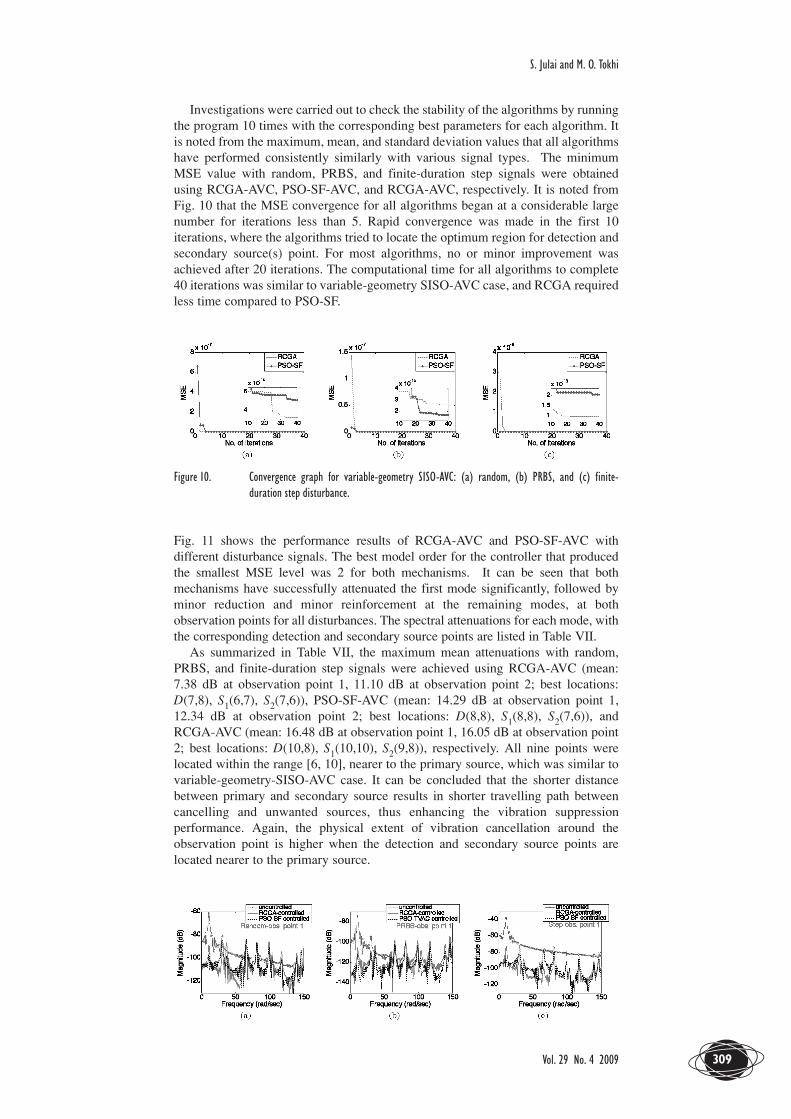
Figure 8. Performance with PRBS disturbance: (a) convergence graph, (b) pole zero plot of RCGA controller, (c) polezero plot of PSO-SF controller, (d) time response at observation point, (e) spectral density of response atobservation point, (f) spectral attenuation, (g) system response before cancellation, (h) system responseafter cancellation for RCGA-AVC, and (i) system response after cancellation for PSO-SF-AVC.
Vol. 29 No. 4 2009
S. Julai and M. O. Tokhi
307
Figure 9. Performance with finite-duration step disturbance: (a) convergence graph, (b) pole zero plot ofRCGA controller, (c) pole zero plot of PSO-SF controller, (d) time response at observation point,(e) spectral density of response at observation point, (f) spectral attenuation, (g) system responsebefore cancellation, (h) system response after cancellation for RCGA-AVC, and (i) system responseafter cancellation for PSO-SF-AVC.
5.2 SIMO-AVCThe control structure in this case comprises one excitation point (P), one detectionpoint (D), two secondary source points (S1 and S2) and the vibration is observed attwo observation points (O1 and O2). The primary source, observation point 1 andobservation point 2 were placed at mesh-points E(7,7), O1(9,14), and O2(13,8),respectively on the plate. The disturbance signals, i.e. random, PRBS, and finite-duration step, were applied to the plate at t = 0.2 to t = 0.5 sec. For the detection andsecondary source points within the predefined range, and with the disturbance types,it was observed that the first five dominant modes of the plate were at 10.35 rad/sec,33.76 rad/sec, 64.94 rad/sec, 81.88 rad/sec, and 99.37 rad/sec. The results presentedin this section are assessed on a comparative basis in terms of spectral densityattenuation for both cases of variable-geometry-AVC and fixed-geometry-AVC withRCGA- and PSO-SF-optimization techniques.
5.2.1 Variable-geometrySimulations were carried out to find the optimal points of detection and secondarysource locations together with controller parameters. Here, the search space of x-and y-section of the plate was reduced from [1, 19] to [5, 15], based on the resultsobtained in variable-geometry-SISO-AVC, i.e. better performance was obtainedwhen the detection and secondary source points were nearer to the primary source.As shown in Fig. 10 and Table VI, the best (minimum) MSE levels obtained withrandom signal using RCGA-AVC and PSO-SF-AVC were 3.21 × 10⁻¹⁴ and 5.13 ×10⁻¹⁴, respectively. The best MSE levels achieved with PRBS as the disturbancesignal were 2.56 × 10⁻¹⁵ and 1.85 × 10⁻¹⁵ using RCGA-AVC and PSO-SF-AVC,respectively. For finite-duration step signal, the MSE levels at the maximumiteration were 9.22 × 10⁻¹⁴ and 2.05 × 10⁻¹³ .
Vibration suppression of flexible plate structures using swarm and geneticoptimization techniques
JOURNAL OF LOW FREQUENCY NOISE, VIBRATION AND ACTIVE CONTROL308
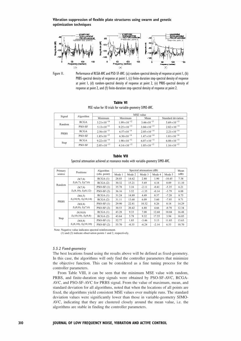
Investigations were carried out to check the stability of the algorithms by runningthe program 10 times with the corresponding best parameters for each algorithm. Itis noted from the maximum, mean, and standard deviation values that all algorithmshave performed consistently similarly with various signal types. The minimumMSE value with random, PRBS, and finite-duration step signals were obtainedusing RCGA-AVC, PSO-SF-AVC, and RCGA-AVC, respectively. It is noted fromFig. 10 that the MSE convergence for all algorithms began at a considerable largenumber for iterations less than 5. Rapid convergence was made in the first 10iterations, where the algorithms tried to locate the optimum region for detection andsecondary source(s) point. For most algorithms, no or minor improvement wasachieved after 20 iterations. The computational time for all algorithms to complete40 iterations was similar to variable-geometry SISO-AVC case, and RCGA requiredless time compared to PSO-SF.
Figure 10. Convergence graph for variable-geometry SISO-AVC: (a) random, (b) PRBS, and (c) finite-duration step disturbance.
Fig. 11 shows the performance results of RCGA-AVC and PSO-SF-AVC withdifferent disturbance signals. The best model order for the controller that producedthe smallest MSE level was 2 for both mechanisms. It can be seen that bothmechanisms have successfully attenuated the first mode significantly, followed byminor reduction and minor reinforcement at the remaining modes, at bothobservation points for all disturbances. The spectral attenuations for each mode, withthe corresponding detection and secondary source points are listed in Table VII.
As summarized in Table VII, the maximum mean attenuations with random,PRBS, and finite-duration step signals were achieved using RCGA-AVC (mean:7.38 dB at observation point 1, 11.10 dB at observation point 2; best locations:D(7,8), S1(6,7), S2(7,6)), PSO-SF-AVC (mean: 14.29 dB at observation point 1,12.34 dB at observation point 2; best locations: D(8,8), S1(8,8), S2(7,6)), andRCGA-AVC (mean: 16.48 dB at observation point 1, 16.05 dB at observation point2; best locations: D(10,8), S1(10,10), S2(9,8)), respectively. All nine points werelocated within the range [6, 10], nearer to the primary source, which was similar tovariable-geometry-SISO-AVC case. It can be concluded that the shorter distancebetween primary and secondary source results in shorter travelling path betweencancelling and unwanted sources, thus enhancing the vibration suppressionperformance. Again, the physical extent of vibration cancellation around theobservation point is higher when the detection and secondary source points arelocated nearer to the primary source.
Vol. 29 No. 4 2009
S. Julai and M. O. Tokhi
309
Figure 11. Performance of RCGA-AVC and PSO-SF-AVC: (a) random-spectral density of response at point 1, (b)PRBS-spectral density of response at point 1, (c) finite-duration step-spectral density of responseat point 1, (d) random-spectral density of response at point 2, (e) PRBS-spectral density ofresponse at point 2, and (f) finite-duration step-spectral density of response at point 2.
Table VIMSE value for 10 trials for variable-geometry SIMO-AVC.
Table VIISpectral attenuation achieved at resonance modes with variable-geometry SIMO-AVC.
5.5.2 Fixed-geometryThe best locations found using the results above will be defined as fixed-geometry.In this case, the algorithms will only find the controller parameters that minimizethe objective function. This can be considered as a fine tuning process for thecontroller parameters.
From Table VIII, it can be seen that the minimum MSE value with random,PRBS, and finite-duration step signals were obtained by PSO-SF-AVC, RCGA-AVC, and PSO-SF-AVC for PRBS signal. From the value of maximum, mean, andstandard deviation for all algorithms, noted that when the locations of all points arefixed, the algorithms yield consistent MSE values over multiple runs. The standarddeviation values were significantly lower than those in variable-geometry SIMO-AVC, indicating that they are clustered closely around the mean value, i.e. thealgorithms are stable in finding the controller parameters.
Vibration suppression of flexible plate structures using swarm and geneticoptimization techniques
JOURNAL OF LOW FREQUENCY NOISE, VIBRATION AND ACTIVE CONTROL310
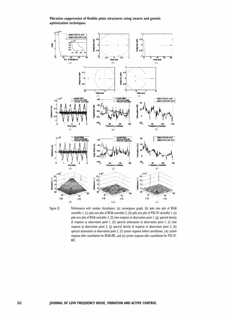
Figs. 12 – 14 show the corresponding results of RCGA- and PSO-SF-AVCperformances using different disturbance signals. The spectral attenuations achievedare summarized in Table IX. It is noted in Fig. 12 that vibration was reduced at bothpoints with RCGA-AVC while reinforcement occurred at the fifth mode at bothpoints with PSO-SF-AVC, with random signal as a primary source. It is noted thatthe mean attenuations achieved with RCGA-AVC were 12.37 dB and 11.07 dB,while 12.92 dB and 12.17 dB with PSO-SF-AVC, at observation point 1 and point2, respectively. By referring to Fig. 13 when the plate was subjected to PRBSdisturbance, the mean spectral attenuation achieved at observation point 1 was 15.35dB with RCGA-AVC and 14.46 dB with PSO-SF-AVC. At observation point 2,mean attenuations of 15.95 dB and 14.79 dB were achieved with RCGA-AVC andPSO-SF-AVC, respectively. Both mechanisms attenuated the vibration significantlyat the first four modes while reinforcement occurred at the fifth mode at bothobservation points with random and PRBS disturbances. Fig. 14 shows theperformance of RCGA-AVC system when the plate was disturbed with finite-duration step disturbance. It is noted that the mean spectral attenuations achieved atobservation point 1 were 17.39 dB and 22.87 dB with RCGA-AVC and PSO-SF-AVC, respectively. For the second observation point, the mean spectral attenuationsachieved were 16.14 dB and 21.42 dB with RCGA-AVC and PSO-SF-AVC. Thevibration was reduced at all dominant modes at both points using both mechanisms.
The level of vibration reduction achieved at the observation points for alldisturbance signals is demonstrated with the time domain responses and spectraldensities of the system responses before and after cancellation in Figs. 12 (f) – (k),13 (f) – (k), and 14 (f) – (k). The deflection throughout the plate is further shownwith the 3-dimensional plots of system response before and after control in Figs. 12(l) – (n), 13 (l) – (n), and 14 (l) – (n). It is noted that significant reduction in platevibration was achieved. Both controllers were stable as revealed by the pole-zeroplots in Figs. 12 (b) – (e), 13 (b) – (e), and 14 (b) – (e). Furthermore, the controlledsignal in time domain at both observation points was at consistent level from 0.3 secto 4 sec. The discrete transfer functions of the controllers at a sampling time of0.0016 sec thus obtained are
(24)
(25)
(26)
(27)
(28)
(29)C zz
z . z .2
0 976 0 963
0 358 0 0652step_PSOSF( ) =
−+ +. .
C zz
z . z .1
0 851
0 856 0 0532step_PSOSF( ) =
− −− +
.
C zz
z . z .2
0 184 0 097
0 296 0 2272PRBS_PSOSF( ) =
− ++ −
. .C z
z
z . z .1
0 228 0 074
0 275 0 3562PRBS_PSOSF( ) =
− +− +
. .
C zz
z z2
0 088 0 140
0 207 0 0522rand_PSOSF( )
. .
. .=
−+ +
C zz
z z1
0 154 0 261
0 031 0 2702rand_PSOSF( )
. .
. .=
− −− −
C zz
z . z .2
328 0 023
0 128 0 0712step_RCGA( ) =
− ++ −
.C z
z
z . z .1
0 193 0 101
0 172 0 0112step_RCGA( ) =
− ++ −
. .
C zz
z . z .2
0 619 0 439
0 261 0 4612PRBS_RCGA( ) =
− +− +
. .C z
z
z . z .1
0 044
0 041 0 0352PRBS_RCGA( ) =
− ++ −
.
C zz
z z2
0 002 0 044
0 133 0 1862rand_RCGA( )
. .
. .=
− ++ +
C zz
z z1
0 362 0 321
0 199 0 1252rand_RCGA( )
. .
. .=
− ++ −
Vol. 29 No. 4 2009
S. Julai and M. O. Tokhi
311
Figure 12. Performance with random disturbance: (a) convergence graph, (b) pole zero plot of RCGAcontroller 1, (c) pole zero plot of RCGA controller 2, (d) pole zero plot of PSO-SF controller 1, (e)pole zero plot of RCGA controller 2, (f) time response at observation point 1, (g) spectral densityof response at observation point 1, (h) spectral attenuation at observation point 1, (i) timeresponse at observation point 2, (j) spectral density of response at observation point 2, (k)spectral attenuation at observation point 2, (l) system response before cancellation, (m) systemresponse after cancellation for RCGA-AVC, and (n) system response after cancellation for PSO-SF-AVC.
Vibration suppression of flexible plate structures using swarm and geneticoptimization techniques
JOURNAL OF LOW FREQUENCY NOISE, VIBRATION AND ACTIVE CONTROL312
Figure 13. Performance with PRBS disturbance: (a) convergence graph, (b) pole zero plot of RCGA controller1, (c) pole zero plot of RCGA controller 2, (d) pole zero plot of PSO-SF controller 1, (e) pole zeroplot of RCGA controller 2, (f) time response at observation point 1, (g) spectral density of responseat observation point 1, (h) spectral attenuation at observation point 1, (i) time response atobservation point 2, (j) spectral density of response at observation point 2, (k) spectralattenuation at observation point 2, (l) system response before cancellation, (m) system responseafter cancellation for RCGA-AVC, and (n) system response after cancellation for PSO-SF-AVC.
Vol. 29 No. 4 2009
S. Julai and M. O. Tokhi
313
Figure 14. Performance with finite-duration step disturbance: (a) convergence graph, (b) pole zero plot ofRCGA controller 1, (c) pole zero plot of RCGA controller 2, (d) pole zero plot of PSO-SF controller 1,(e) pole zero plot of PSO-SF controller 2, (f) time response at observation point 1, (g) spectraldensity of response at observation point 1, (h) spectral attenuation at observation point 1, (i) timeresponse at observation point 2, (j) spectral density of response at observation point 2, (k) spectralattenuation at observation point 2, (l) system response before cancellation, (m) system responseafter cancellation for RCGA-AVC, and (n) system response after cancellation for PSO-SF-AVC.
Table VIIIMSE value for 10 trials for fixed-geometry SIMO-AVC.
Vibration suppression of flexible plate structures using swarm and geneticoptimization techniques
JOURNAL OF LOW FREQUENCY NOISE, VIBRATION AND ACTIVE CONTROL314
Table IXSpectral attenuation achieved at resonance modes with fixed-geometry SIMO-AVC.
Note: Negative value indicates spectral reinforcement.
5.3 Comparative assessment of system performancesIt follows from the results presented in the previous sections that, in case ofvariable-geometry-SISO and variable-geometry-SIMO, RCGA-AVC hassuccessfully achieved the highest mean spectral attenuation in PRBS-SISO-AVC,random-SIMO-AVC, and step-SIMO-AVC, while PSO-SF-AVC performed well inrandom-SISO-AVC, step-SISO-AVC, and PRBS-SIMO-AVC. The best location fordetection and secondary source(s) points were found to be within the x- and y-section of [6, 10] on the flexible plate. This indicates that the vibration can becontrolled better if detection and secondary source(s) points are located nearer to theprimary source. In AVC, locations of both sensors and actuators are determined inthe simulation environment before implemented in the experiment. It is veryimportant to decide only one combination of location for sensors and actuators tocater for all type of disturbance signals in a practical environment. In this work, afew combinations of these locations found with either random, PRBS, or finite-duration step signals because of the stochastic search nature of the algorithms.Therefore, a combination of locations found with random signal may be the best tochoose for the experimental work since this signal is generally considered to moreclosely replicate a real world situation.
As presented in Tables II and VI, the standard deviations of the MSE value forvariable-geometry cases were relatively higher than those in fixed-geometry casesshown in Table IV and VIII. In variable-geometry, SISO-AVC case utilized 12design variables (two set of (x, y) coordinates for detection and secondary sourcepoints and 8 controller parameters) while in SIMO-AVC case, 14 design variables(three sets of (x, y) coordinates for detection and secondary source points and 8controller parameters) were utilized. In contrast, SISO- and SIMO-AVC fixedgeometry cases dealt with fewer design variables, i.e. 8 for SISO- and 8 for SIMO-AVC, resulting in a consistent value of MSE and relatively low standard deviation.The large number of design variables has contributed to the high standard deviationin variable-geometry. Also, the effect of the location of detection and secondarysource points has significant influence on the performance of the controlled system.
In terms of level spectral attenuation achieved as listed in Tables III and V,variable-geometry-AVC systems have shown significant vibration reduction with allthe systems at the first dominant mode for all the disturbances. As presented inTables V and VIII, the vibration reduction obtained with fixed-geometry-AVCsystems at this mode was considerably higher than those in variable-geometry cases.This is followed by minor attenuation or reinforcement at the other modes which hasinsignificant effect to the overall reduction in vibration level. Considering that mostof the vibration energy is in the first dominant mode, attenuation obtained of morethan 25 dB at this mode reduced the vibration considerably either with variable-geometry- or fixed-geometry-AVC systems.
Vol. 29 No. 4 2009
S. Julai and M. O. Tokhi
315
For fixed-geometry-SISO and fixed-geometry-SIMO cases, RCGA-AVC hassuccessfully achieved the highest mean spectral attenuation in step-SISO-AVC, andPRBS-SIMO-AVC, while PSO-SF-AVC performed superior in random-SISO-AVC,PRBS-SISO-AVC, random-SIMO-AVC and step-SIMO-AVC. The results presentedhave shown that all the controllers performed well in suppressing the vibration ofthe plate structure, especially at the first dominant mode. The performance of thesystem with the SIMO controller was significantly better than that with the SISOcontroller. The improvement in mean spectral attenuation by utilizing a multiple setof cancelling sources, i.e. SIMO case, for RCGA-AVC and PSO-SF-AVC atobservation point 1 was 97.60% and 86.98% for random signal. For PRBS signal,improvements of 121.07% and 2.77% have been achieved in mean attenuation at thesame observation point with RCGA-AVC and PSO-SF-AVC, respectively.Improvements of 34.70% and 78.81% have been achieved with RCGA-AVC andPSO-SF-AVC, respectively, at observation point 1 with finite-duration step signal.It was noted that most cases have achieved more than 50% improvement in spectralattenuation. This implies that the utilization of a multiple set of cancelling sourcesenhances the performance of the system in terms of vibration reduction.
6. CONCLUDING REMARKSIn this paper, the development of an AVC strategy with GA and PSO techniques hasbeen presented. The controllers have been designed based on direct optimization ofthe location of the detector and secondary source, and the controller parametersbased on minimizing the MSE level of the error (observed) signal. Theperformances of GA and PSO based AVC systems have been assessed withinsimulation environment of a flexible plate system with different types ofdisturbances. The results have shown that both RCGA and PSO-SF have the abilityto find the best combination of location of the detector and secondary sources,together with controller parameters. It has been demonstrated that all the developedcontrol systems performed successfully in suppressing the vibration of the system.The utilization of multiple set of cancelling sources in SIMO case has been shownto enhance the performance of the system in terms of vibration reduction comparedto SISO case. Overall, the results indicate that both GA and PSO algorithms can beused effectively for optimal placement of system components and optimization ofcontrollers for vibration suppression in flexible structures.
ACKNOWLEDGMENTSS. Julai acknowledges the financial support of the Ministry of Higher EducationMalaysia and University of Malaya, Kuala Lumpur, Malaysia.
REFERENCES[1] Hu Q., A composite control scheme for attitude maneuvering and elastic mode
stabilization of flexible spacecraft with measurable output feedback, Journalof Aerospace Science and Technology, 2009, 13 (2-3), 81-91.
[2] Suleman A. and Costa A. P., Adaptive control of an aeroelastic flight vehicleusing piezoelectric actuators, Journal of Computers & Structures, 2004, 82(17-19), 1303-1314.
[3] Liu, L. K. and Zheng, G. T., Parameter analysis of PAF for whole-spacecraftvibration isolation, Journal of Aerospace Science and Technology, 2007, 11(6), 464-472.
[4] Sinha, J. K., Vibration-based diagnosis techniques used in nuclear powerplants: An overview of experiences, Journal of Nuclear Engineering andDesign, 2008, 238 (9), 2439-2452.
Vibration suppression of flexible plate structures using swarm and geneticoptimization techniques
JOURNAL OF LOW FREQUENCY NOISE, VIBRATION AND ACTIVE CONTROL316
[5] García, B., Burgos, J. C. and Alonso, Á. , Winding deformations detection inpower transformers by tank vibrations monitoring, Journal of Electric PowerSystems Research, 2005, 74 (1), 129-138.
[6] Siringoringo, M. and Fujino, Y., System identification of suspension bridgefrom ambient vibration response, Journal of Engineering Structures, 2008, 30(2), 462-477.
[7] Kang, Y. K., Park, H. C., Kim, J., and Choi, S. B., Interaction of active andpassive vibration control of laminated composite beams with piezoceramicsensors/actuators, Materials & Design, 2002, 23 (3), 277-28.
[8] Tokhi, M. O., The design of active noise control systems for compact anddistributed sources, Journal of Sound and Vibration, 1999, 225 (3), 401-424.
[9] Rashid, A. and Mihai Nicolescu, C., Active vibration control in palletisedworkholding system for milling, International Journal of Machine Tools andManufacture, 2006, 46 (12-13), 1626-1636.
[10] Kumar, K. R. and Narayanan, S., Active vibration control of beams withoptimal placement of piezoelectric sensor/actuator pairs, Smart Materials andStructures, 2008,17 (5), 1-15.
[11] Han, J. H. and Lee, I., Optimal placement of piezoelectric sensors andactuators for vibration control of a composite plate using genetic algorithms,Smart Materials and Structures, 1999, 8 (2), 257–267.
[12] Wei, L., Zhiku, H. and Demetriou, M. A., A computational scheme for theoptimal sensor/actuator placement of flexible structures using spatial H2measures, Mechanical Systems and Signal Processing, 2006, 20 (4), 881-895.
[13] Hongwei, Z., Lennox, B., Goulding, P. R. and Leung, A. Y. T., A float-encoded genetic algorithm technique for integrated optimization ofpiezoelectric actuator and sensor placement and feedback gains, SmartMaterials and Structures, 2000, 9, 552–557.
[14] Rao, A. K., Natesan, K., Seetharama, B. M., and Ganguli, R., ExperimentalDemonstration of H∞ Control based Active Vibration Suppression inComposite Fin-tip of Aircraft using Optimally Placed Piezoelectric PatchActuators, Journal of Intelligent Material Systems and Structures, 2008, 19(6), 651-669.
[15] Montazeri, A., Poshtan, J. and Yousefi-Koma, A., The use of ‘particle swarm’to optimize the control system in a PZT laminated plate, Smart Materials andStructure, 2008, 17 (4), 1-15.
[16] Mat Darus, I. Z. and Tokhi, M. O., Soft computing-based active vibrationcontrol of a flexible structure, Engineering Applications of ArtificialIntelligence, 2005, 18 (1), 93-114.
[17] Mohd Hashim, S. Z., and Tokhi, M. O., Genetic Modelling and Simulation ofFlexible Structures. Studies in Informatics and Control, 2004, 13 (3), 253-264.
[18] Shaheed, M. H. and Tokhi, M. O., Dynamic modelling of single-link flexiblemanipulator: parametric and non-parametric approaches, Robotica, 2002, 20,93–109.
Vol. 29 No. 4 2009
S. Julai and M. O. Tokhi
317
[19] Braik, M., Sheta, A., and Arieqat, A., A Comparison between GAs and PSOin Training ANN to Model the TE Chemical Process Reactor, Proceedings ofSymposium on Affective Language in Human and Machine, AISB Convention,2008, 1 – 7.
[20] Mat Darus, I. Z. and Tokhi, M. O., Finite Difference Simulation of a FlexiblePlate Structure, Journal of Low Frequency Noise, Vibration and ActiveControl, 2004, 23 (1), pp. 27-46.
[21] Timoshenko, S. and Woinowsky-Krieger, S., Theory of plates and shells,McGraw-Hill Book Company, New York, 1959.
[22] Leissa, A. W., Vibration of plates, Scientific and Technical InformationDivision Office of NASA, NASA SP-160, Washington, D.C. 1969.
[23] Holland, J., Adaptation in natural and artificial systems, University ofMichigan Press, USA, 1975.
[24] Goldberg, D. E., Real-coded genetic algorithms, virtual alphabets, andblocking, Complex Systems 5, 1991, 139-168,
[25] Herrera, F., Lozano, M., Verdegay, J. L., Tackling real-coded geneticalgorithms: operators and tools for behavioural analysis, Artificial IntelligenceReview, 1998, 12 (4), 265-319.
[26] Baker, J. E., Reducing bias and inefficiency in the selection algorithm,Proceedings of the Second International Conference on Genetic Algorithmsand their Application, Cambridge, Massachusetts, USA, 1987, 14-21.
[27] Kennedy, J. and Eberhart, R. C., Particle swarm optimization, Proceedings ofIEEE Conference on Neural Networks IV, Piscataway, NJ, 1995, 1942 – 1948.
[28] Eberhart, R. C. and Yuhui, S., Tracking and optimizing dynamic systems withparticle swarms, Proceedings of the IEEE of Congress on EvolutionaryComputation, 2001, 94-100.
[29] Shi, Y. and Eberhart, R., A modified particle swarm optimizer, Proceedings ofthe IEEE Congress on Evolutionary Computation, Anchorage, AK , USA,1998, 69-73.
[30] Abd Latif, I. and Tokhi, M. O., Fast convergence strategy for particle swarmoptimization using spreading factor, Proceedings of the IEEE Congress onEvolutionary Computation, Trondheim, Norway, 2009, 2693-2700.
[31] Ratnaweera, A., Halgamuge, S. K., and Watson, H. C., Self-organizinghierarchical particle swarm optimizer with time-varying accelerationcoefficients, IEEE Transactions on Evolutionary Computation, 2004, 8 (3),240-255.
[32] Mohd Hashim, S. Z., Tokhi, M. O., and Mat Darus, I. Z., Active vibrationcontrol of flexible structures using genetic optimization, Journal of LowFrequency Noise, Vibration and Active Control, 2006, 25 (3), 195-207.
[33] Lottin, J., Formosa, F., Virtosu, M., and Brunetti, L., About optimal locationof sensors and actuators for the control of flexible structures. Research andEducation in Mechatronics, KTH, Stockholm, 2006, 1-4.
Vibration suppression of flexible plate structures using swarm and geneticoptimization techniques
JOURNAL OF LOW FREQUENCY NOISE, VIBRATION AND ACTIVE CONTROL318


![“Queensland Statute Reprints”...QUEENSLAND NOISE ABATEMENT ACT 1978-1983 [Reprinted as at 1 October, 1983] Noise Abatement Act 1978, No. 51 As amended by Noise Abatement Act Amendment](https://static.documents.pub/doc/80x56/6003423d15a35e295d1d5a34/aoequeensland-statute-reprintsa-queensland-noise-abatement-act-1978-1983-reprinted.jpg)


