Addressing 21 CFR Part 11Requirements with anAutomated Configuration AuditTrail and Version ManagementSystem
Addressing 21 CFR Part 11Requirements with anAutomated Configuration AuditTrail and Version ManagementSystemby David Deitz
This articledescribes howconfigurationsoftware changesare commonlytracked andmanaged todayusing “paper-based”configurationaudit trails, theshortcomings ofthe paper-basedsolutions, and anew automatedcomputer-basedconfigurationaudit trail thataddresses theshortcomings ofthe traditionalpaper-basedsolutions.
Introduction
Designing and implementing process con-trol software is an interactive and on-going process. There are several rea-
sons for this. In some instances, specificationsfor the process control software lack the neces-sary detail to accurately design and implementthe required control in a single attempt. Inothers, the process equipment that the processcontrol software must interact with lacks fea-tures or functionality that it was assumed tosupport at the time the process control softwarewas designed. Even in a ‘perfect’ situation inwhich the process control software was imple-mented exactly as specified and no process equip-ment issues needed to be addressed, configura-tion software changes would undoubtedly berequired as the process is optimized to maxi-mize product quality and throughput.
When process control software is designedand implemented within a facility that is regu-lated by the FDA, procedures must be put inplace to ensure that the software can be vali-dated to perform as expected. In this case, theneed for change control policies and procedureshas been documented in numerous guidelines
and papers on computer systems validation. Inaddition, the computer systems validationlifecycle models developed by the PDA andGAMP both identify the importance of ongoingchange monitoring and change management.
A Conventional Approach:The Paper-Based Configuration
Audit TrailWith the understanding that configuration soft-ware changes will occur, and that change con-trol is an integral component of computer sys-tems validation, all manufacturers who operateregulated facilities have implemented some formof a configuration software change manage-ment system. Presently, the overwhelmingmajority of these facilities have implementedpaper-based systems for tracking configurationsoftware changes (i.e. a paper-based configura-tion audit trail).
As an element of the overall validation pro-tocol, a SOP is usually developed to guide indi-viduals who may modify the process controlsoftware (e.g. automation and control engineers,process engineers, instrument technicians, etc.)as to how software changes are to be docu-
mented. For the remainder of this article, individuals who maymodify the process control software will be generically referredto as “configuration software engineers.” By carefully follow-ing and adhering to the requirements defined in the SOP, theconfiguration software engineers are manually generating aconfiguration audit trail. Usual requirements spelled out in asoftware change management SOP that are specific to docu-menting configuration software changes often include thefollowing:
• Every software file must contain a file header that supportsuser-entered comments.
• The configuration software engineer is responsible for up-dating the file header with a remark that documents thescope of the change whenever the software is modified.
• The configuration software engineer is responsible for in-cluding remarks within the software as necessary to easilyand readily identify portions of the software that have beenmodified.
• Remarks placed in the file header should include the nameof the individual who implemented the change, as well asthe date and time that the change was made.
• The file’s version identifier should be updated after anyalteration is made to the configuration software.
• A paper printout of the modified software must be gener-ated.
• The paper printout of the changed software must be filedand available for future inspection and review.
It is apparent from this list of tasks that the manual effortrequired to develop and produce a configuration audit trail issubstantial and places a significant burden on the configura-tion software engineers.
Drawbacks of the Paper-Based ConfigurationAudit Trail Approach
Although paper-based software audit trails have been usedextensively by industry for many years and are still the customtoday, the approach is not ideal. There are several potentialdrawbacks to the paper-based audit trail:
• Training and familiarization with the SOP. The paper-based system relies on each configuration software engi-neer to have a thorough understanding of requirements inthe change management SOP that are pertinent to theprocedures to be followed to adequately document configu-
ration software changes. As such, it is crucial that eachmember of the project team receives training on the SOP.Providing this training at the beginning of a new project fora new project team can usually be accomplished in anefficient and cost-effective manner. However, as the projectprogresses through its lifecycle, the project team will con-tinue to evolve. Ensuring that new members of the “evolv-ing” team are sufficiently trained on the SOP is much morechallenging, much less efficient, and significantly less costeffective.
• Consistency and accuracy of the paper-based audittrail. Because the audit trail is created manually by theconfiguration software engineers, each engineer is free todecide what level of detail is required to adequately docu-ment the changes that they have implemented. This isespecially problematic when the configuration softwareengineer who made the modification and is documenting itis very familiar with the software being modified. In thisscenario, configuration software engineers tend to providea minimal amount of information and detail in their re-marks. This can create substantial problems for individualswho are responsible for the software from a long-termperspective (i.e. plant operations personnel). These indi-viduals are very likely to be much less familiar with thesoftware than the configuration software engineer whoimplemented the modification, and may not be able toreadily discern the complete scope of the change based onthe limited comment provided.
• Accountability issues associated with the paper-basedaudit trail. With a paper-based configuration audit trail,there is no mechanism to ensure that descriptions of changesare actually recorded at the time the software is beingaltered, or that the configuration software engineer whomade the changes is the individual who actually updatedfiles with the information about the change. Additionally,in the heat of start-up, it is very easy for modifications to beoverlooked, and hence go undocumented.
• Difficulty with definitively linking a version of soft-ware that is actually running in the control system toa specific version of the software in a paper-basedsystem. This paper-based configuration audit trail systemdoes not capture events such as the downloading of a newversion of a software module. As such, there is no way toeasily assure that the version of a piece of software execut-ing in the controller is identical to a particular version ofsoftware in the paper based files.
• Paper-based audit trail is a document managementnightmare. Significant investments in personnel and spaceare required to ensure that all the paper versions of thesoftware which are created over the life of the processcontrol system are filed in such a way that they can bereadily found for inspection and review.
• Paper-based configuration audit trail requires theconfiguration software engineers to spend a signifi-cant portion of their time and energy on document-ing change rather than optimizing the process. Theuse of highly skilled and highly compensated engineers todevelop configuration audit trail documentation is an inef-fective use of configuration software engineering resources,
and a tremendous cost burden to the project. In addition, thetime that configuration software engineers spend on creat-ing paper based documentation is time that can not be spenton improving the operation of the facility to increase produc-tion.
• Paper-based configuration audit trails may not beacceptable to the regulatory agency (i.e. the FDA).Process control software is included in the definition ofelectronic records as defined in 21 CFR Part 11 §11.3(b)(6).Within 21 CFR Part 11, subpart b, §11.10 lists severalspecific controls and practices that may be required toensure the authenticity and integrity of electronic records.Controls and practices identified in the section which might
be especially relevant to this discussion include items§11.10(e) which states “Use of secure, computer-gener-ated, time-stamped audit trail to independently recordthe date and time of operator entries and actions thatcreate, modify, or delete electronic records…,” anditem §11.10(k)(2) which states “Revision and changecontrol procedures to maintain an audit trail thatdocuments time-sequenced development and modifi-cation of systems documentation.” Given the state-ments of §11.10 (e) and §11.10 (k)(2), it is reasonable toconclude that computer based audit trails may be the onlyacceptable way of tracking changes in electronic records inthe near future.
While paper-based configuration audit trails have been thecustom for the past several years, it is apparent from the list ofpotential shortcomings associated with this approach thatthere is room for significant improvement.
A New Method: An Automated Computer-Based Configuration Audit Trail and Version
Management SystemAfter reviewing the drawbacks of the paper-based configura-tion audit trail, one would quickly conclude that significantimprovements could be made in the area of software changemanagement if the paper-based configuration audit trail couldbe replaced by a computer-based system that automaticallytracked process control software changes.
One system that contains an automated computer-basedconfiguration audit trail and version management applicationis the DeltaV system by Fisher-Rosemount Systems. Theconfiguration audit trail and version management software istightly integrated with the software engineering environmentand provides transparent software change tracking, includingthe automated capture of “who,” “when,” and “what” type data.Version-to-version comparisons of any software module maybe viewed using either a graphical or textual differencesviewing feature. The system also provides a mechanism to“roll-back” to an earlier version of a software module, as wellas traceability of configuration software versions to the run-time environment. Access to the audit trail and version man-agement system is integrated with and managed by the secu-rity system.
The tight integration between the configuration audit trailand version management system and the software engineeringenvironment facilitates transparent collection of configurationaudit trail data, and addresses applicable requirements from21 CFR Part 11. The following sections of this article discuss therequirement for specific procedures and controls that are enu-merated in 21 CFR Part 11, and how these procedures andcontrols have been implemented in the configuration audit trailand version management application.
The Automated Configuration Audit Trail andVersion Management System - SoftwareRevision History and Version-to-Version
Comparisons21 CFR Part 11 specifies that processes and controls shall beemployed to ensure the authenticity and integrity of electronicrecords. Specific procedures and controls relevant to the soft-ware revision histories and version-to-version comparisonaspects of the automated configuration audit trail and versionmanagement system include:
• §11.10(a) “Validation of systems to ensure accuracy, reli-ability, consistent intended performance, and the ability todiscern invalid or altered records.”
• §11.10(b) “The ability to generate accurate and completecopies of records in both human readable and electronic formsuitable for inspection, review, and copying by the Agency…”
• §11.10(e) “Use of secure, computer generated time-stampedaudit trails to independently record the date and time ofoperator entries and actions that create, modify, or deleteelectronic records…”
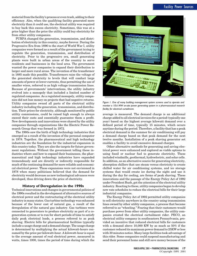
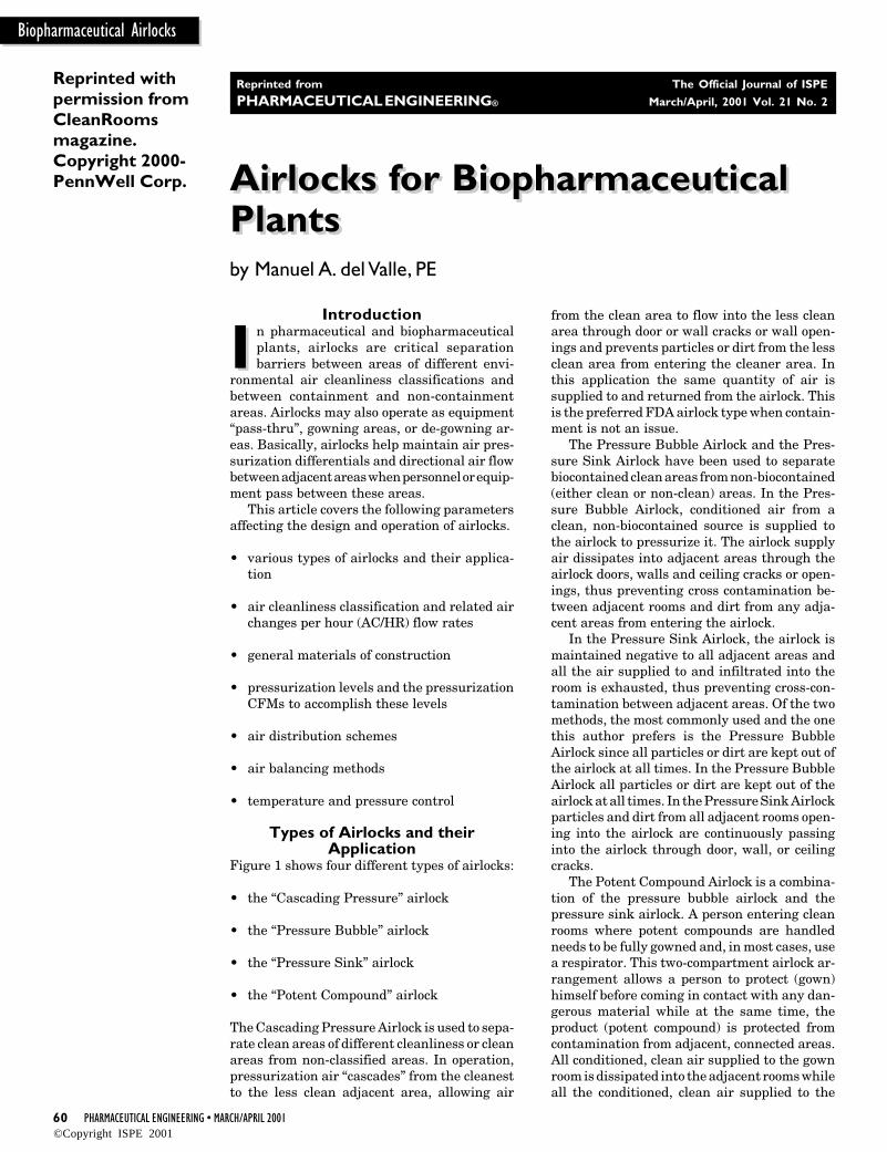
When the configuration audit trail and version managementsystem is enabled, software modules must be “checked-out” bythe configuration software engineer before they can be altered.After the altering of an item has been completed, it must be“checked-in” to the configuration audit trail and version man-agement system before it may be downloaded to a controldevice. When the request is made to check-in a softwaremodule, the configuration audit trail application automati-cally records the name of the user performing the “check-in”and the date and time the “check-in” of the software modulewas performed. The version identifier for the software modulebeing “checked-in” is automatically updated as part of the“check-in” process. To illustrate this feature, an example of asoftware module’s version history is presented in Figure 1.
When a software module is “checked in,” the configurationsoftware engineer is offered an opportunity to enter a commentthat will be attached to the “check-in” event. The comment fieldmay be used to provide additional detail about the extent of thealteration that was made, enter a revision control number thatthe change is related to, or provide other detailed informationthat the configuration software engineer may deem important.
The comment associated with the check-in of an item maybe viewed by merely selecting a specific version of the softwaremodule from the module revision history (Figure 1), and thenselecting the “Details” button on the version history dialog.Figure 2 presents an example of a software module “check-in”comment.
The automated configuration audit trail and version man-agement system collects all of the required version history
Figure 6. Function security lock assignments.
information automatically as an integral piece of the configu-ration software development process. For this reason, no spe-cial effort is required on the part of the configuration softwareengineer to collect or manage software module version historydata.
Collecting and displaying revision history information isonly one part of monitoring and tracking configuration soft-ware changes. A second and equally important part of theautomated configuration audit trail application is its ability toautomatically detect and display changes that have occurredbetween different versions of a software module.
Since most configuration software modules are developedusing graphical configuration techniques, the automated con-figuration audit trail and version management system hasbeen designed to support graphical version-to-version com-parisons. When viewing graphical differences, color-coding isemployed to identify information on the diagram that has beenadded, modified, or deleted. A graphical version-to-versioncomparison is shown in Figure 3.
Many configuration software changes are alterations toinformation within a graphical element rather than the actualaddition or deletion of a graphical element. When graphicalelements contain information that has been altered, they areidentified as “changed” elements on the graphical comparisonview. However, in many cases, additional details about thechange that has occurred within the graphical element arerequired. To support more detailed analysis, the configurationaudit trail and version management system also offers theability to view “textual” based differences.
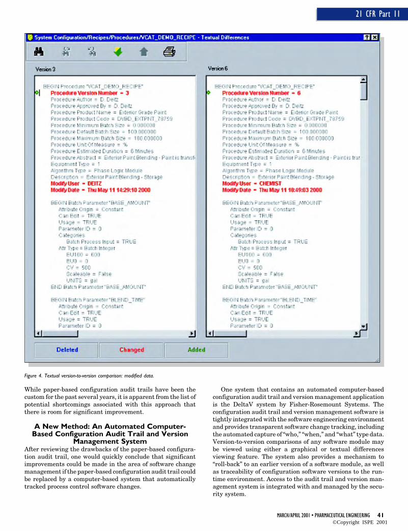
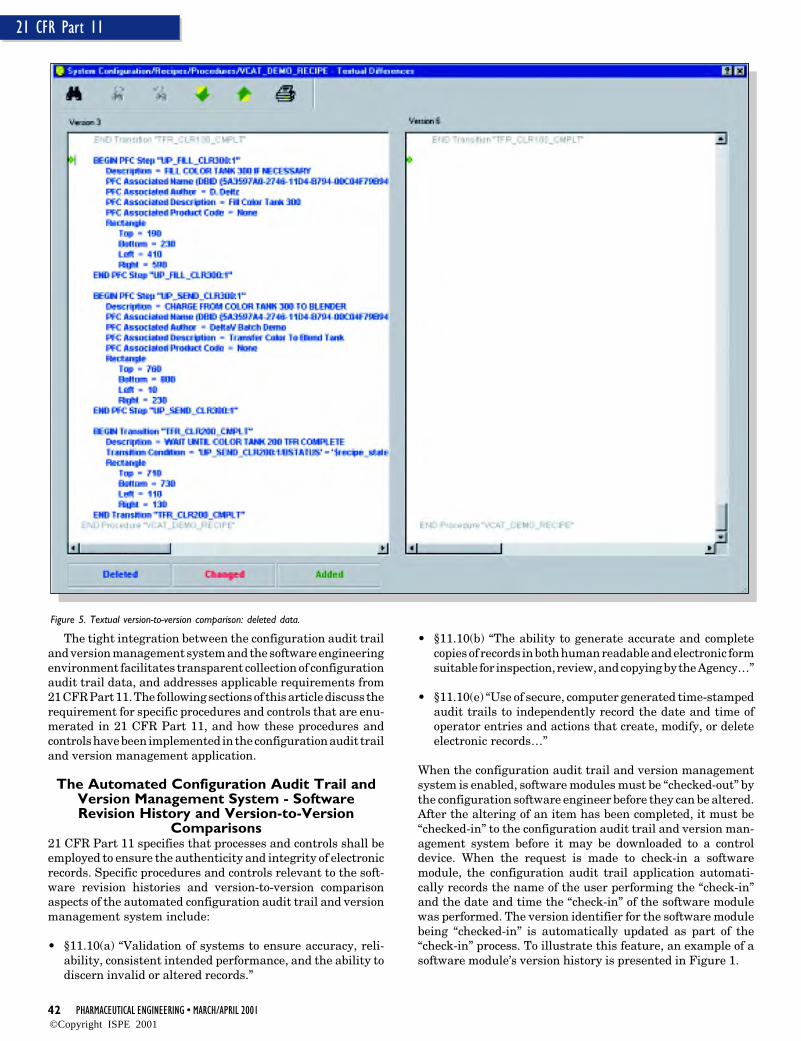
Textual based differences give a more detailed comparisonof information associated with a software module that is notreadily viewable in the graphical comparison view (e.g. actionsthat are defined within a step). In addition, the textual baseddifferences view also gives a mechanism for comparing soft-ware modules that do not have graphical views (e.g. a nameset). Figures 4 and 5 show the results of a textual version-to-version comparison.
As Figures 4 and 5 clearly depict, the automated configura-tion audit trail and version management system provides theuser with a clear, consistent, and accurate depiction of configu-ration software engineering changes. Again, as was the casewith the software module version history, all the informationrequired to support version-to-version comparisons is col-lected automatically as an integral part of the configurationsoftware development process, and requires no extra effort onthe part of the configuration software engineer.
All revision history information, as well as graphical andtextual version-to-version comparisons can be printed forinspection and review, thus ensuring compliance with theprocedures and control outlined in §11.10(b).
The Automated Configuration Audit Trail andVersion Management System - Version Rollback21 CFR Part 11 specifies that procedures and controls shall beused to ensure the authenticity and integrity of electronicrecords. Specific procedures and controls pertaining to theversion rollback aspects of the automated configuration audittrail and version management system include:
• §11.10(c) “Protection of records to enable their accurate andready retrieval throughout the records retention period.”
• §11.10(e) “…Record changes shall not obscure previouslyrecorded information…”
There are instances when it is necessary to be able to revertback to a previous version of a software module. For example,in a flexible manufacturing facility, the user may employdifferent versions of a software module to make differentproducts (e.g. version 3 of a temperature control module is usedto make product A, while version 5 of the temperature controlmodule is used to make product B). To serve the requirementto be able to revert back to previous versions of a softwaremodule, a “rollback” function has been included in the auto-mated configuration audit trail and version managementsystem.
From the module history dialog, the configuration softwareengineer can select a previous version of a software module and“rollback” the module to that version. The internal softwaremechanisms that are used to perform the rollback have beendesigned to ensure that the rollback to the previous version ofsoftware does not obscure any later versions, or preclude thefuture recall of the later versions.
The Automated Configuration Audit Trail andVersion Management System - Configuration
and Runtime Software Version Linkages21 CFR Part 11 contains no specific requirements relating tothe ability to correlate version information for a softwaremodule in the process control system configuration databaseand a copy of that module in the process control device. However,by providing mechanisms to ensure that the software modules
running in the controller can be linked to a specific version of thesoftware module in the configuration database, the total integ-rity of the system is enhanced.
The automated configuration audit trail and version man-agement system provides three mechanisms that were specifi-cally implemented to ensure that it is possible to establish alink between a specific version of a software module (as viewedin the software module’s revision history) to the version of thesoftware module that is operating in the control device. Thesethree mechanisms include:
• No software module can be downloaded if it is “checked-out”of the configuration audit trail and version managementsystem. This ensures that only versions of the module thatare visible in the software module’s revision history can bedownloaded.
• The downloading of a software module to a control deviceautomatically produces an entry in that module’s revisionhistory. The entry in the version history reveals the devicethat the module was downloaded to. An example of thisfunctionality is depicted in Figure 1.
• The software module version number is downloaded to thecontrol device for all control modules and recipe elements.
By adding this functionality in the automated configurationaudit trail and version management system, inspectors andauditors can be assured that the software executing in thecontrol device is, in fact, the same software that exists in theconfiguration database.
The Automated Configuration Audit Trail andVersion Management System - User Access
Controls21 CFR Part 11 specifies that processes and controls shall beemployed to ensure the authenticity and integrity of electronicrecords. Specific processes and controls that are relevant to theuser access controls aspects of the automated configurationaudit trail and version management system include:
• §11.10(d) “Limiting access to authorized individuals.”
• §11.10(g) “Use of authority checks to ensure that onlyauthorized individuals can use the system…”
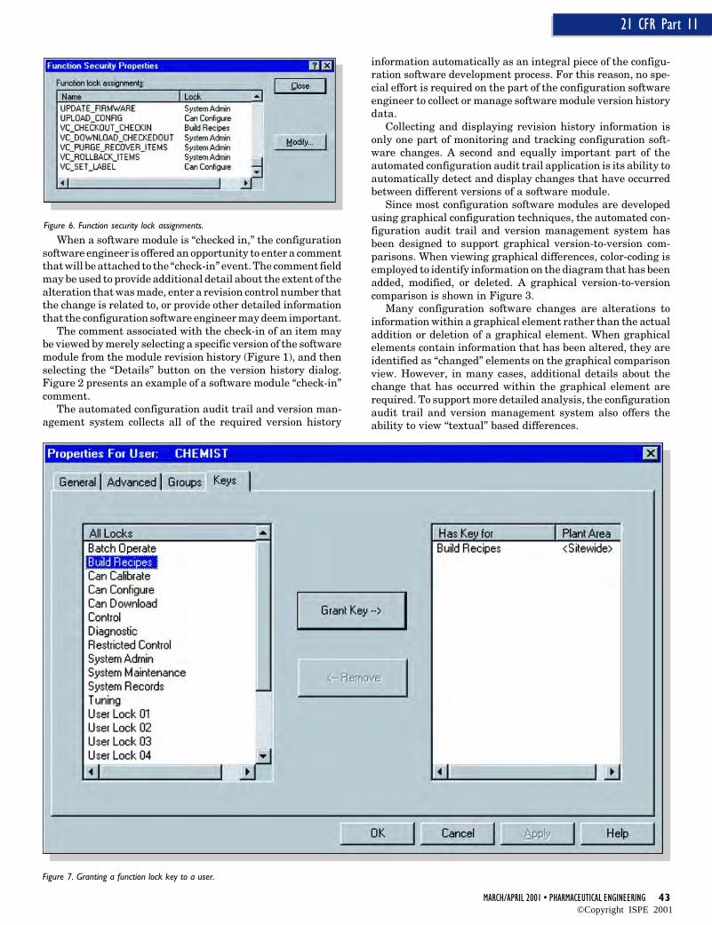
The configuration audit trail and version management systemapplication is tightly integrated with the system securityservices. As an example, the system administrator must grantfunction lock “keys” to individuals in order for those individu-als to be able to perform actions such as checking items in andout of the configuration system, performing a version rollback,or setting database labels.
Using these function lock key assignment capabilities, thesystem administrator has the ability to create a class of userswith “read-only” capabilities. By supporting the concept of a“read-only” user within the configuration audit trail and ver-sion management application, individuals who need to reviewand inspect the system configuration can readily do so. How-ever, because these users have a “read-only” authorization,they are prevented by the security system from being able tomake any modifications to the configuration software.
Figure 6 presents user locks associated with the configura-tion audit trail and version management system. Figure 7displays the dialog that the system administrator interactswith to grant function lock keys to individual users.
The tight integration between the configuration audit trailand version management application ensures that only userswho have the required security keys are allowed to access and/or modify the software modules.
ConclusionAt this time, paper-based configuration audit trail and versionmanagement systems are still the standard. However, auto-mated computer-based configuration audit trail and versionmanagement systems have several advantages over paper-based systems, and as such, are better suited to addressing therequirements of 21 CFR Part 11 which are applicable to themanagement and tracking of changes to process control soft-ware. Computer-based systems are more accurate and reliablethan traditional paper-based systems with respect to detectingand documenting configuration software change and also pro-vide functionality that does not exist in a paper-based system.
There are also substantial cost savings to be realized withthe use of the automated configuration software and versionmanagement application. The tight integration between theautomated configuration audit trail and version managementapplication and the process control software developmentenvironment significantly reduces the cost of configurationchange tracking, and eliminates the requirement for configu-ration software engineering resources to perform “no-value”work that is better handled by the automated system. Bymaking better use of engineering resources already within the
organization, it is frequently possible to execute additionalprocess optimization projects that may significantly improvethe corporate bottom line.
In view of the many benefits that an automated configura-tion audit trail and version management system provides, it isalmost a certainty that this approach will quickly become thenew standard.
References1. “Food and Drugs,” 21 CFR, Part 11 (Federal Register, U.S.
Government Printing Office, Washington, DC, 4/1/99 Edi-tion).
About the AuthorDave Deitz is the DeltaV Batch Product Manager. In this role,he has responsibility for defining the functional requirementsfor the DeltaV Batch Product Suite, and delivering that func-tionality to the marketplace.He joined the Fisher Controlssystems engineering group in June, 1981, and has held anumber of positions of increasing responsibility with Fisher-Rosemount. He has focused almost exclusively on the designand implementation of batch process control systems through-out his career. In 1991, he accepted a position as the pharma-ceutical industry consultant for Fisher-Rosemount Systems,and in 1995 was named the DeltaV Batch product manager.Deitz has a BS in chemical engineering from the University ofNorth Dakota and an MS in biochemical Engineering from theUniversity of Texas at Austin. He is a member of ISA, ISPE,and The World Batch Forum.
Commissioning and Qualification:The ISPE Baseline® GuideCommissioning and Qualification:The ISPE Baseline® Guide
Tby Christopher Wood
This article wasreprinted withpermission fromEuropeanPharmaceuticalReview, Spring2000 edition.
T he delivery of manufacturing facilitiesregulated by FDA or other regulatoryauthorities pose significant challenges
to manufacturers, engineering professionals andequipment suppliers. These facilities are re-quired to meet cGMP regulations while remain-ing in compliance with all other governing codes,laws and regulations.
The cost and time required to bring suchfacilities on line has been increasing, in manycases due to inconsistent interpretation of regu-latory requirements. The International Societyfor Pharmaceutical Engineering (ISPE) and en-gineering representatives from a broad base ofhealthcare companies have entered into a part-nership with the Food and Drug Administra-tion (FDA) to enhance understanding of“baseline” cGMP requirements for facilities.
As part of this initiative, an integrated Euro-pean and US team of senior pharmaceuticalengineering and QA representatives has beenworking and consulting with the industry todraft the ISPE Baseline® Commissioning andQualification Guide, publication of which isanticipated early in 2001. This guide aims todefine key terms and offer a consistent interpre-tation, while still allowing a flexible and inno-vative approach to facility design, construction,commissioning and qualification.
This article aims to describe the goals, phi-losophy and key concepts being suggested withinthe guide.
ScopeThe Guide will address the process of designing,constructing, commissioning and qualifying thefacilities, utilities and equipment regulated byFDA or other health authorities. The guide willneither be a standard or a GMP and is notintended to replace governing laws, codes, etc.that apply to facilities of this type.
Neither will strict adherence to the guideguarantee that a facility will be acceptable toFDA or any other regulatory body. While thismight be a disappointment to those who seek a“check-box” solution to their qualification prob-lems, the guide does not aim to absolve pharma-ceutical manufacturers of the responsibility tothink carefully, but to provide a framework
within which sensible decisions can be madeand supported.
Last, the Guide does not address ProcessValidation. This subject is well defined by FDAand other authorities and substantial guidancealready exists.
However Commissioning and Qualificationactivities are the foundation upon which Pro-cess Validation is built. Furthermore, theseactivities play a crucial role in delivering opera-tionally effective, safe and efficient facilities,utilities and equipment. Therefore, it is impor-tant to ensure that a comprehensive approach isundertaken during the commissioning and quali-fication process. A well conceived and executedcommissioning and qualification plan cangreatly facilitate a timely and cost effectiveprocess validation effort.
GoalsThere are two primary goals of the Commission-ing and Qualification Baseline® Guide. The firstis to bring a common terminology and method-ology to the commissioning and qualificationprocess that can be used by manufacturers,facility designers, contractors and equipmentsuppliers. The second is to provide a systemimpact assessment process to bring structureand consistency in determining the potentialimpact of engineering systems on product qual-ity. An important secondary goal is to foster aninterdisciplinary team approach to commission-ing and qualification.
PhilosophyThe basic philosophy promoted by the Guide isthat:
• Good Engineering Practice (GEP) makes asignificant contribution to meeting the regu-latory demands of the pharmaceutical in-dustry.
• Where engineering systems may have a Di-rect Impact on product quality, supplemen-tary Qualification Practices (in addition toGEP and Commissioning) are required tofully address pharmaceutical industry de-mands.
• The Baseline® approach is to restrictthe application of Qualification Prac-tices to Direct Impact Systems andbuild on the contribution of GEP andCommissioning.
• Good Engineering Practice is a satis-factory approach for Indirect or NoImpact Systems.
System ImpactIt is the function of the facility, equip-ment or utility that determines whatlevel of commissioning and qualifica-tion are needed:
• Direct Impact Systems are ex-pected to have an impact on productquality
• Indirect Impact Systems are notexpected to have an impact on prod-uct quality
This differentiation between systemtype is important and should determinethe attention and effort given to eachand by whom. Therefore, the determi-nation as to whether the system is di-rect or indirect impact is a key issue.System impact assessment providesthe thought process as well as some keyquestions that must be addressed inmaking the assessment.
Some concern has been expressedthat designating a system “indirect im-pact” might be a means of doing lessthan full testing on a system that mightrequire it. This is not the intention. Theobjective is that through a comprehen-sive impact assessment process, thosesystems presenting a risk to productquality are identified and given the at-tention appropriate to this level of risk,and by the right people (e.g. QA Depart-ments).
For this process to work it is essen-tial that an explicit rationale is pro-vided for the impact assessment andthat the rationales are fully understood,documented and endorsed by QA de-partments. This places a responsibilityupon engineers to communicate clearlythe nature of operation of engineeringsystems, and their potential impact onproduct quality.
Design for ImpactThis term is used to describe the prac-tice of making conscious design deci-sions with respect to the impact of thesystem in operation at the beginning ofdesign development. By careful design,
the number of systems capable of havinga direct impact can be reduced; the directimpact functions remain but the sys-tems with which they are associated arechosen by the designer.
Good Engineering PracticeGood Engineering Practice, commonlyreferred to as GEP, is proven and ac-cepted, cost-effective, engineering meth-ods and practices that ensure the effec-tive satisfaction of stakeholder require-ments. As such, GEP ensures that anengineering project meets the require-ments of the user while being cost effec-tive, compliant with regulations and welldocumented. Guidance and standardsthat have been defined by engineeringinstitutes and other learned bodies sup-port GEP. For direct impact systems,GEP is supplemented by QualificationPractices with the active participation ofQuality Assurance personnel.
Enhanced Design ReviewEnhanced Design Review1 has beendefined within the guide as:A documented review of the design, at anappropriate stage in a project, for con-formance to operational and regulatoryexpectations.
A structured review of the design offacilities, utilities and equipment is notan FDA demand (although draft Euro-pean GMP requirements suggest thatthis could become a European require-ment in the form of Design Qualifica-tion (DQ)).
However Enhanced Design Review(EDR) has been positioned in the Guideas the “smart” way to prepare for IQ andOQ. It is in the interests of all to revealdesign or specification problems througha rigorous, structured review processearly in a project rather than discoverthem later, where a remedy might in-volve significant delay and expense.However, with the exception of com-puter based systems, a structured anddocumented approach to assessing de-sign, whether in the form of EDR or DQ,currently remains a business risk drivenchoice not a regulatory demand.
How should designs be assessed?There are many approaches (e.g.FMECA) however the rigor of themethod by which the design is exam-ined should be commensurate with:
• the impact of the system
• system complexity
• familiarity or degree of novelty withthe system and-or the supplier
• the novelty of application i.e. stan-dard equipment put to a new use
A familiar system of simple design withno impact on product quality should besubject to sufficient scrutiny duringdesign development as part of GoodEngineering Practice, and performanceof an FMEA-type approach (for example)could be excessive in such circum-stances.
CommissioningThe term Commissioning typically en-compasses the following tasks:
• physical completion (a milestone)
• inspection
• setting-to-work
• regulation and adjustment
• testing and performance testing
• planning and preparation associatedwith managing the above activities
These terms and their associated tasksdescribed within Codes of Practice etc.define GEP for commissioning andshould form the foundations for Instal-lation and Operational Qualification.
Qualification PracticesThese are the general characteristics ofa Qualification regime and include:
• active participation of Quality As-surance
• enhanced documentation, documentmanagement and a structured ap-proval process
• QA change control
• greater end user participation
• use of Qualification Rationales toidentify what should be checked, how,to what extent, why and by whom.
• deciding what not to check and why.
In line with the guide philosophy, Com-missioning activities performed withinsuch a regime would comprise IQ/OQ.
52 PHARMACEUTICAL ENGINEERING • MARCH/APRIL 2001
Commissioning and Qualification
Qualification Relationships -The V-Model
The V-Model is a simple and easily un-derstood means of describing the rela-tionship between the User Require-ments and the designs and specifica-tions prepared to meet them, and thelevels of inspection and testing per-formed as part of Commissioning andQualification.
Figure 1 illustrates the V-model for aDirect Impact System requiring Quali-fication; the Qualification tasks areequivalent to those described for com-missioning but are supplemented by themore rigorous controls of QualificationPractices. The V-Model illustrates:
• To Commission or Qualify a systemeffectively, the performance, con-struction and operational require-ments of a system should be known.
• PQ is used to verify the User Require-ments.
• OQ verifies the functional require-ments (of an individual system).
• IQ verifies the construction and in-stallation.
• Factory Acceptance Tests are opera-tional checks and these can and shouldcontribute to the OQ where practical.
• Pre-delivery Inspection is a construc-tion check and these can and shouldcontribute to IQ where practical.
For some items of equipment, the con-struction and operation can be checkednearly completely at the supplier’s works,leaving only the inspection associatedwith site installation, and the testingassociated with integration with othersystems. This is an opportunity toprogress with IQ and OQ.
Build on the PotentialContributions
of your SuppliersThe V-Model focuses on the basic lifecyclerequired by the end-user, however thisneglects the contribution that could bemade by the procedures, systems anddocumentation used and followed by asupplier or contractor. In many cases thesupplier or contractor will have theirown quality system (e.g. ISO 9001 parts1-3) that demands a structured approachwith equivalent relationships betweenQualification tasks as represented bythe V-model; in effect their own V-model.Where this is the case, the usual prac-
tices of the contractor or supplier can beintegrated within the Qualification ef-fort owned by the end-user.
The Role of Quality AssuranceThe Quality Assurance departmentplays an essential role during the Com-missioning and Qualification process.Although in the past Quality Assurance(QA) may not have been involved withCommissioning and Qualification untilthe later stages in a project, early in-volvement is being encouraged and pro-moted within the Guide as this willdeliver the following benefits:
• An understanding from QA of thefacility, processes and equipmentwell in advance of use for commer-cial manufacture
• QA can ensure commissioning ac-tivities are performed within a Quali-fication regime where they can sup-port Qualification activities andeliminate duplication of effort.
• A partnership is established betweenEngineering and QA that ensuresefficient hand-over for commercialstart-up
Figure 1.
MARCH/APRIL 2001 • PHARMACEUTICAL ENGINEERING 53
Commissioning and Qualification
Commissioning has traditionally beenviewed as an engineering activity whereQA involvement was unnecessary.
Summary• Good Engineering Practice (including
Commissioning) makes a significantcontribution to meeting the regula-tory demands of the pharmaceuticalindustry.
• GEP should be supplemented withQualification Practices where sys-tems have a Direct Impact on productquality.
• Impact Assessment must be supportedby QA-endorsed rationales.
• How we choose to use some systemsdetermines their Impact - design care-fully with desired impact in mind.
• Adopt a multidisciplinary approachand encourage the early involvementof QA.
• The Baseline® approach is to designfor No or Indirect Impact and onlyapply Qualification Practices to Di-rect Impact Systems.
Footnote1. The Term “DQ” has not been used to
avoid confusion between the FDAinterest in the design of medical de-vices and that of facilities, utilities,and equipment.
AcknowledgementsThe author also would like to acknowl-edge the contributions of the ISPEBaseline® Commissioning and Qualifi-cation Guide team that are implicitwithin this article.
About the AuthorChristopher Wood is an InnovationManager with GlaxoSmithKline and Co-Team Leader of the ISPE Baseline®
Commissioning and Qualification GuideTask Team Team.
A failure analysis conducted to establishthe cause of corrosive pitting and themode of failure for a biowaste spool
piece revealed an important insight regardingsystem design. Results of the analysis suggestthat base chemistries and thermal history playa significant role in the potential for ferriteformation in 316L stainless steel. These resultsindicate that the alloy makeup of 316L stain-less steel used in the construction of a systemwill have a strong effect on how long the systemwill withstand a corrosive environment. Ac-cordingly, the chemical makeup of 316L shouldbe considered when designing systems forwelded applications that experience corrosiveservice.
AISI 316L is commonly used in many indus-tries, including the bioprocess or pharmaceuti-cal industries, in fluid system applications. 316Lstainless steel is mostly iron with significantalloying additions of chromium, which gives themetal its “stainless” or corrosion-resistant char-acteristics, and nickel, which stabilizes the aus-tenite and makes the metal nonmagnetic andtough. In terms of performance, cost, and avail-ability, this alloy is the optimum choice.
In bioprocess applications, large systems ofAISI 316L tubing are orbitally/autogenouslywelded in place. As a method of construction,welding is fast and avoids the crevices (andpotential for crevice corrosion) common withmechanical couplings. Unacceptable weld char-
acteristics include bead meander, oxidation, andslag formation. There are also cosmetic geomet-ric issues, such as weld bead width and height.
Cleaning in Place (CIP) is common inbioprocess applications. The systems must avoidcorrosion in service as corrosion products willcontaminate the final product. Bioprocess ap-plications are usually wet, which introduces thepossibility of rouging and microbially inducedcorrosion. Rouge is a contaminant found inmany hot water and steam systems consistingof various forms of iron oxide; these iron oxidesare a corrosion product that can affect the purityof the final product. Rouge is often treated byshutting down, cleaning, and repassivating theentire system. Microbially Induced Corrosion(MIC) initiates in the heat affected zones ofwelds, as well as in crevices or cracks. MICoccurs when aerobic and anaerobic microbescreate a colony by removing material, formingdeep pits with small pinhole openings on theinterior of the tube. Presence of MIC in a systemcan speed up corrosive processes drastically; asystem designed to work for 10 years can fail intwo years or less if MIC is present.
Pitting corrosion is the most common failuremode in welded 316L, and therefore the mode ofconcern. Pitting is a form of localized attackcaused by a breakdown in the thin passive oxidefilm that protects stainless steel from the corro-sion process. Pits are commonly the results of aconcentration cell established by a variation insolution composition in contact with the alloy.
Figure 1. Components in weldedassembly.
Component Description Construction
1 0.5 in. long sanitary flange fitting Machined from thick wall tubing
2 10 in. long tubing Welded and drawn tubing
3 4.5 in. long tubular 90° elbow fitting Hydroformed tubing
4 10.25 in. long tubing Welded and drawn tubing
5 1.75 in. long sanitary flange fitting Machined from thick wall tubing
This articlepresents theresults of acorrosion failureanalysisconducted toestablish thecause ofcorrosive pittingand the mode offailure for abiowaste spoolpiece.
These variations occur when the solution at a surface irregular-ity (such as an inclusion) is different from that of the bulksolution composition. Once a pit has formed, it acts as an anodesupported by a large cathodic region. Pits often nucleate atspecific microstructural features in the weld deposit. In welded316L, these features include d-ferrite in an austenite matrix, ormicrosegregation of alloying elements in the dendritic weldmicrostructure.
BackgroundA failure analysis was conducted on a biowaste spool piececonsisting of a welded assembly, which showed evidence ofcorrosive attack - Figure 1. This failure was considered to bepremature since the assembly had been in service for onlyabout two years, as a piece of the transfer line between thecollection vessel and a kill vessel in a bioprocess system. Thesystem fluid was a dilute aqueous stream of salts, sugars, andproteins, operated at ambient pressure and temperature. Thesample was steam-sterilized prior to shipment for analysis,but was not cleaned.
The five components of the assembly had been orbitally andautogenously welded together for a total of four welds; the weldbeads appear to have been made using a manual TIG weldingprocedure. The interior surfaces of all four welds had discretepitting concentrated at the 2 o’clock position on the sideopposite to the direction of the weld. In addition, there weretwo bands of haze on either side of each weld, approximately2.5 mm from the edge of the weld bead. A discolored ring wasvisible, approximately 10 mm from the edge of the weld bead,on the interior surfaces of Components #2 and #4. Isolatedpinpoint pits were evident on the interior and exterior surfacesnear the second weld (Component #2) at the 6 o’clock position.
The spool piece was in service in a horizontal position. Thetop and bottom of each weld was identified, and a distinct
difference was noted in the corrosive pitting between the twohalves. The top had many pits and a brown residue. The bottomhad a few larger pits and no noticeable residue.
Failure occurred due to corrosive pitting that breached thewall thickness of a welded and drawn tubing component(Component #2), approximately 10 mm from the edge of theweld of a tubular elbow fitting (Component #3), at the 6 o’clock(bottom) position. The failure was located at the intersection ofthe Heat-Affected Zones (HAZs) of the orbital weld and theseam weld in Component #2.
The following sections outline the analytical procedure, testresults, and possible causes for corrosion and failure.
Analytical ProcedureA complete metallurgical analysis was performed to establishthe mode of failure and to determine whether other measurescould be taken to avoid premature failure by corrosion. Thefollowing procedures were followed:
• Document the assembly as received with photographs andmeasurements; make a scale drawing of the assembly.
• Measure ferrite content in welds with a ferrite indicator anda Ferritscope; measure magnetic permeability µ with amagnetic permeability indicator.
• Section assembly into five component parts and four weldparts.
• Perform SpectroChemical Analysis (SCA) on samples of thefive component parts to determine elemental makeup of the316L stainless steel.
• Perform roughness readings on the five component parts
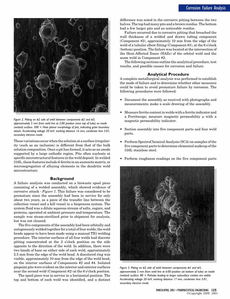
Figure 2. Pitting on #2 side of weld between components #2 and #3,approximately 5 mm from weld line at 2:00 position (near top of tube) on inside(wetted) surface. 500 ×. Note planar morphology of pits, indicating grain boundaryattack. Accelerating voltage 20 keV, working distance 16 mm, condenser lens 3.01,secondary electron mode.
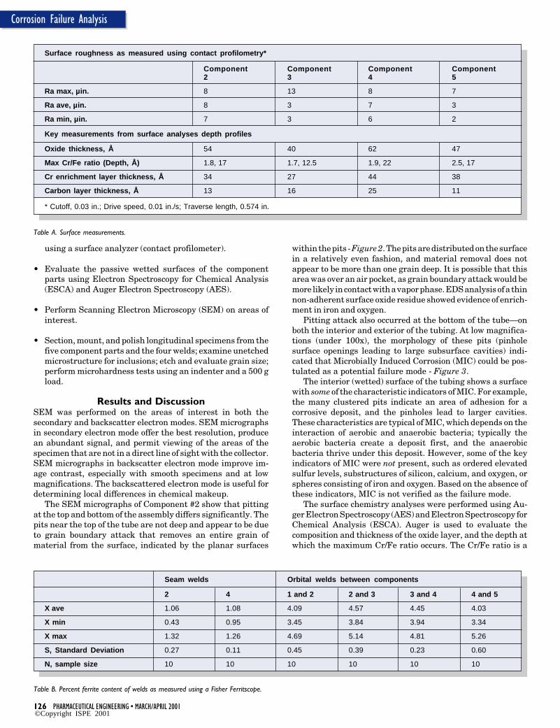
Figure 3. Pitting on #2 side of weld between components #2 and #3,approximately 5 mm from weld line at 6:00 position (at bottom of tube) on inside(wetted) surface. 80 ×. Pinholes leading to larger subsurface cavities are visible.Accelerating voltage 20 keV, working distance 17 mm, condenser lens 3.01,secondary electron mode.
• Evaluate the passive wetted surfaces of the componentparts using Electron Spectroscopy for Chemical Analysis(ESCA) and Auger Electron Spectroscopy (AES).
• Perform Scanning Electron Microscopy (SEM) on areas ofinterest.
• Section, mount, and polish longitudinal specimens from thefive component parts and the four welds; examine unetchedmicrostructure for inclusions; etch and evaluate grain size;perform microhardness tests using an indenter and a 500 gload.
Results and DiscussionSEM was performed on the areas of interest in both thesecondary and backscatter electron modes. SEM micrographsin secondary electron mode offer the best resolution, producean abundant signal, and permit viewing of the areas of thespecimen that are not in a direct line of sight with the collector.SEM micrographs in backscatter electron mode improve im-age contrast, especially with smooth specimens and at lowmagnifications. The backscattered electron mode is useful fordetermining local differences in chemical makeup.
The SEM micrographs of Component #2 show that pittingat the top and bottom of the assembly differs significantly. Thepits near the top of the tube are not deep and appear to be dueto grain boundary attack that removes an entire grain ofmaterial from the surface, indicated by the planar surfaces
within the pits - Figure 2. The pits are distributed on the surfacein a relatively even fashion, and material removal does notappear to be more than one grain deep. It is possible that thisarea was over an air pocket, as grain boundary attack would bemore likely in contact with a vapor phase. EDS analysis of a thinnon-adherent surface oxide residue showed evidence of enrich-ment in iron and oxygen.
Pitting attack also occurred at the bottom of the tube—onboth the interior and exterior of the tubing. At low magnifica-tions (under 100x), the morphology of these pits (pinholesurface openings leading to large subsurface cavities) indi-cated that Microbially Induced Corrosion (MIC) could be pos-tulated as a potential failure mode - Figure 3.
The interior (wetted) surface of the tubing shows a surfacewith some of the characteristic indicators of MIC. For example,the many clustered pits indicate an area of adhesion for acorrosive deposit, and the pinholes lead to larger cavities.These characteristics are typical of MIC, which depends on theinteraction of aerobic and anaerobic bacteria; typically theaerobic bacteria create a deposit first, and the anaerobicbacteria thrive under this deposit. However, some of the keyindicators of MIC were not present, such as ordered elevatedsulfur levels, substructures of silicon, calcium, and oxygen, orspheres consisting of iron and oxygen. Based on the absence ofthese indicators, MIC is not verified as the failure mode.
The surface chemistry analyses were performed using Au-ger Electron Spectroscopy (AES) and Electron Spectroscopy forChemical Analysis (ESCA). Auger is used to evaluate thecomposition and thickness of the oxide layer, and the depth atwhich the maximum Cr/Fe ratio occurs. The Cr/Fe ratio is a
1 Cr equivalent = Cr + 1.37 Mo + 1.5 Si + 2 Nb + 3 Ti; all values in weight percent.
2 Ni equivalent = Ni + 0.31 Mn + 22 C + 14.2 N + Cu; all values in weight percent.
3 At values of Cr eq/Ni eq below 1.5, the solidification mode is austenitic or austenitic-ferritic, which corresponds to a cosmeticallyunacceptable weld. For values of Cr eq/Ni eq between 1.5 and 2.0, the solidification mode is ferritic-austenitic. Welds with this solidificationmode are acceptable. However, the higher the number is, the higher the propensity for the formation of ferrite.
measure of the chromium enrichment in the passive oxide film.It is defined as the maximum ratio of chromium to iron withinthe oxide layer. The depth of enrichment is the location withinthe oxide layer where Cr/Fe equals 1. The oxide thickness isdefined as the depth at which the Full Width Half Maximum(FWHM) of the oxygen peak occurs. ESCA is used to determinethe quantitative surface composition including contaminants.ESCA provides information on chemical makeup and on thenature of the chemical bonds as well. The total Cr/Fe ratio isdefined as the relative concentration of Cr and Fe withinapproximately the outer 50Å. This measure includes Cr and Fein oxide and metallic states, and also indicates the relativechromium enrichment in the passive layer. The CrO/FeO ratiois the ratio of Cr in the oxide state to Fe in the oxide state.
The ESCA and AES analyses provided no unusual findings.Samples were taken from representative non-corroded areasto ascertain whether there were differences in the surfaceoxide chemistries and thicknesses that would contribute tocorrosion initiation. The oxide thicknesses, oxide composi-tions, and maximum Cr/Fe ratios are representative of resultsfrom electropolished and passivated 316L stainless steel sur-faces. The Cr/Fe value of the samples ranged from 1.5 at 17Åto 2.5 at 17Å . The oxide layers ranged from 40 Å to 62 Å. Thesurface carbon thickness of the samples ranged from 11 Å to 25Å. The chromium depth enrichment of samples ranged from 27to 44 Å - Table A. Elemental surveys of the surfaces displayelements associated with stainless steel as well as typical
process contaminants, which include silicon, sulfur, phospho-rous, carbon, nitrogen, and contaminants indicative of han-dling (potassium, calcium, and sodium). Note: Surface rough-ness data and surface chemistry (ESCA and AES) results arenot available for Component #1. Once samples were taken forspectrochemical analysis to determine base chemistry and formetallographic mounts to examine microstructure, there wasno material remaining for these other test methods. Spectro-chemical analysis is a destructive method that requires at least50 g of material. However, since Component #1 did not partici-pate in the failure and it appeared relatively unaffected by itsexposure, it was determined that chemical makeup and micro-structure were sufficient information.
In addition, surface roughness readings showed no signifi-cant differences. All components had average surface rough-ness under 10 µin. These measurements also indicate smooth,electropolished surfaces.
Of particular interest in this failure is that only the weldedand drawn tubing components (Components #2 and #4) showany evidence of corrosive attack—and only in the vicinity of theweld. In fact, the other components looked as good as new andprobably could have continued to function. Based on thechemistries and microstructures of Components #2 and #4, itcan be assumed that they came from the same heat of tubing.An optical metallographically prepared surface etched to re-veal grain size reveals a variation in grain size between thesurface and the interior. This microstructure, with larger grains
to be acceptable. However, the higher this number is, the higherthe propensity for the formation of ferrite in an orbital autog-enous weld. 3 Welding technique may have some effect on thesolidification mode since it can affect the weld metal composi-tion through dilution and nitrogen pickup. However, for therelatively small and precise welds common in autogenouswelding for higher purity applications, the overall effect ofsolidification conditions is of secondary importance, and solidi-fication mode is largely determined by chemistry.4 Under prac-tical solidification conditions, the transition between austen-itic-ferritic and ferritic-austenitic solidification modes occurswhen Cr eq/Ni eq = 1.5 ± 0.03.
As Cr eq/Ni eq increases, the higher the propensity for theformation of ferrite. A small amount of d-ferrite reduces thetendency for hot cracking when 316L is welded.5,6 However, thepresence of d-ferrite in welded austenitic stainless steel hasbeen found to stimulate pitting corrosion,7 and recent specifi-cations indicate a very low allowable d-ferrite for use of weldedcomponents in corrosive service.8 Current research indicatesthat corrosion resistance is significantly affected in orbitallywelded 316L when delta ferrite exceeds 3% in the weld.9
At ratios of 1.68 and 1.66, Components #2 and #4 are wellabove the ratios of 1.45 to 1.54 for the other three components.The high Cr eq/Ni eq values, combined with the incompleteanneal and the thermal excursion caused by the welding,increases the tendency for the formation of ferrite.
ConclusionsFailure occurred due to corrosive pitting that breached thewall thickness of welded and drawn tubing (Component #2),approximately 10 mm from the edge of the weld with Compo-nent #3, at the 6 o’clock position. The seam weld of Component#2 had been bead reduced, but had not been fully annealed, asshown by a ferrite indication along the seam and the duplexgrain size of the microstructure. The orbital weld connectingthe tubing and the elbow fitting (Components #2 and #3)intersected with the seam weld of the tubing (Component #2)at the 6 o’clock position, resulting in a localized ferrite contentin excess of 4.5 %. This localized microstructure, in combina-tion with the aqueous environment and time of exposure,provided the necessary and sufficient conditions for corrosivefailure to occur. Only Components #2 and #4 showed anyevidence of corrosive attack, and only in the vicinity of theweld.
Chemistries and thermal history will impact the potentialfor ferrite formation in 316L, which in turn affects corrosionresistance. This finding is particularly important in weldedapplications in corrosive service. As illustrated by this failure,piping systems in bioprocess applications are often constructedof different heats of 316L with significant variations in compo-sition. In the welded condition, some of these heats will havemore retained ferrite, and can experience premature failuredue to corrosion. The Cr eq/Ni eq can be used to evaluate theeffects of the material composition on ferrite formation. Keep-ing ferrite under 3% in orbital welds can improve systemperformance, reduce the potential for corrosion byproduct con-tamination, and reduce downtime for emergency system main-tenance.
at the surfaces and finer grains in the interior, occurs when aworked part is not annealed completely.
The measurable ferrite in the seam welds of both compo-nents also indicates an incomplete anneal, which may mark ahigher propensity for failure. The failure was located at theintersection of the Heat-Affected Zones (HAZs) of the orbitalweld and the seam weld in Component #2. The average ferritecontent was measured using a Ferritscope. At this location,average ferrite content was 4.57 %, the highest ferrite contentin the entire assembly - Table B.
The Difference is Chemical MakeupComponents #2 and #4 differed from the other components inchemical makeup - Table C. Minor changes in the chemistriesof 316L stainless steel can alter the way the alloy solidifiesduring welding. Possible solidification modes for 316L includeaustenitic, austenitic-ferritic, or ferritic-austenitic.
• The austenitic weld solidifies completely as austenite andno further high-temperature transformations occur.
• The austenitic-ferritic weld solidifies as austenite, and deltaferrite is formed from the melt retained between the auste-nite dendrites.
• In the ferritic-austenitic weld, ferrite solidifies first andaustenite forms between the ferrite dendrites. The austen-ite subsequently grows into the ferrite, resulting in a sig-nificant decrease in the volume fraction of the ferrite. Atroom temperature, the weld is substantially austenite witha small volume of retained ferrite.
The competition between ferrite-promoting elements and aus-tenite-promoting elements can be described by the chromiumand nickel equivalents. The chromium equivalent takes intoaccount those elements that promote the formation of ferrite,which is the stable bcc form of iron. The nickel equivalentaccounts for those elements that promote the formation ofaustenite, the metastable fcc form of iron. In austenitic stain-less steels, there must be enough chromium present to formthe stable chromic oxide layer (which gives the steel its stain-less characteristics) balanced by enough austenite formingelements to stabilize the crystal structure as austenite. Thereare several commonly used chromium and nickel equivalents,but the equations developed by Hammar and Svensson1 showan excellent correlation between composition and solidifica-tion mode, especially for austenitic stainless steels. (All valuesin weight percent.)
Cr eq = Cr + 1.37 Mo + 1.5 Si + 2 Nb + 3 Ti, andNi eq = Ni + 0.31 Mn + 22 C + 14.2 N + Cu
Using these equations, solidification mode can be predicted bythe ratio of Cr eq/Ni eq.2 At values of Cr eq/Ni eq below 1.5, thesolidification mode is austenitic or austenitic-ferritic, whichcorresponds to a cosmetically unacceptable weld. For values ofCr eq/Ni eq between 1.5 and 2.0, the solidification mode isferritic-austenitic. Welds with this solidification mode appear
References1. Hammar, O. and U. Svennson, Solidification and Casting of
Metals, The Metals Society, London, 1979, pp. 401-410.
2. Suutala, N. and T. Moisio, “Use of Chromium and NickelEquivalents in Considering Solidification Phenomena inAustenitic Stainless Steels,” Solidification Technology inthe Foundry and Casthouse, The Metals Society, London,1983, pp. 310-314.
3. Collins, S.R. and P. C. Williams, “Weldability and Corro-sion Studies on AISI 316L Electropolished Tubing,” JointMedia: First Technical Conference Ultra-Pure Media 1999,Dresden, Germany, 2-3 November 1999, pp. 29-41.
4. Suutala, N., “Effect of Solidification Conditions on theSolidification Mode in Austenitic Stainless Steel Welds,”Met. Trans. A, Vol. 14, Feb. 1983, pp. 191-197.
7. Savage, W.F. and D.J. Duquette, “Localized Corrosion andStress Corrosion Cracking Behavior of Austenitic StainlessSteel Weldments Containing Retained Ferrite: AnnualProgress Report,” Report COO-2462-6, Renssalaer Poly-technic Institute, Mar. 1980, p. 9.
8. Morach, R. and P. Ginter, “Influence of Low d-Ferrite Contenton the Corrosion Behaviour of Stainless Steels,” StainlessSteel World, Sep. 1997, pp. 55-59.
9. Collins, S.R. and P.C. Williams, “Weldability and CorrosionStudies of AISI 316L Electropolished Tubing,” Interphex2000 Conference Proceedings, New York, New York, 21-23March 2000, pp. 295-306.
About the AuthorSunniva R. Collins is Research Metallurgist for Swagelokwhere she is responsible for assessing technical issues con-cerning materials with special emphasis on semiconductorand biopharm applications. Collins received her PhD and MSEin materials science and engineering from Case WesternReserve University (Cleveland, Ohio) and her BA from theUniversity of Michigan (Ann Arbor, Michigan). She serves onSEMI’s North American Task Forces on Corrosion, SurfaceAnalysis, and Stainless Steel. She is also a member of severaltechnical societies, including the Metallurgical Society (TMS),the Iron and Steel Society (ISS), the International Metallo-graphic Society (IMS), and the American Powder MetallurgyInstitute (APMI). She is currently serving as Chair of theCleveland Chapter of ASM International. Collins has authoredmore than a dozen publications and made more than 30presentations on a variety of metallurgical topics.
Swagelok, 4800 E. 345th St., Willoughby, OH 44094.
Productivity in PharmaceuticalResearch and DevelopmentProductivity in PharmaceuticalResearch and Development
Tby Michael R. Pavia
This articlepresents futureopportunities andchallenges for thepharmaceuticalindustry thatarise from thehuman genomeeffort.
T he information obtained from the se-quencing of the human genome is af-fording the pharmaceutical industry a
huge opportunity; however, the industry alsofaces enormous challenges due to lack of pro-ductivity. To take maximal advantage of theseopportunities, the drug discovery and develop-ment process must be redefined by increasingthe probability of success, reducing the time tomarket, and introducing truly personalizedmedicine. These approaches will fuel futureinnovation and ultimately change the currentpractice of medicine.
The year 2000 represents a very importantyear for the pharmaceutical industry. This wasthe year the sequence of the human genome wascompleted. In fact, future generations may verywell look back years from now and rememberthis year and this event as the most significantin the history of human healthcare.
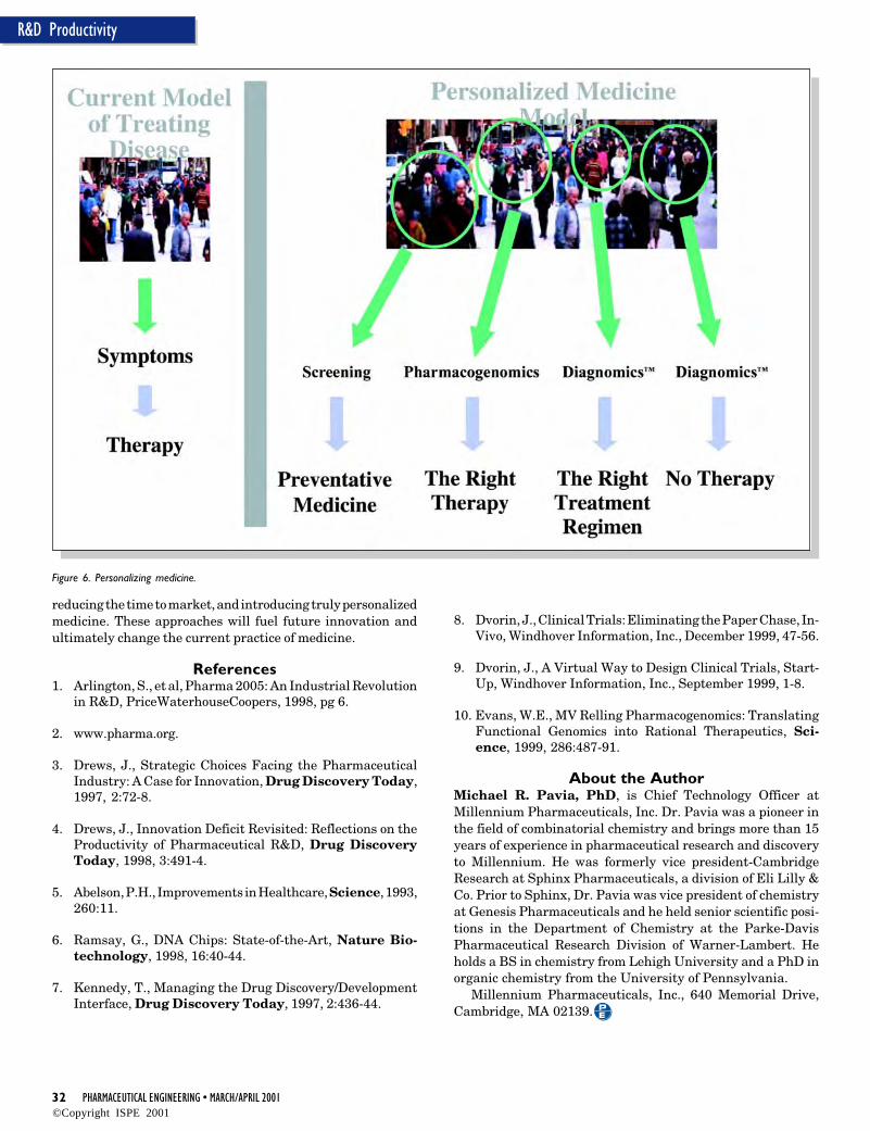
The information supplied within the humangenome represents a foundation for tremen-dous progress and opportunity in medicine-from new targets for improved therapeutics totruly personalized medicine. When the revolu-tion in electronic communication is included, itis not hard to imagine the practice of medicinebeing radically different then it is today. Thebeneficiaries of this radical change will be theentire human race.
This article will discuss two of the pharma-ceutical industry’s greatest opportunities forthe next decade that arise directly or indirectlyfrom the genome effort, as well as the associatedchallenges. These two areas are 1) the use ofnew high-throughput technologies to radicallyimprove the productivity of the pharmaceuticaldiscovery and development process, and 2) per-sonalized medicine.
ProductivityIt is a well-publicized fact that all of the drugsintroduced to the market over the entire historyof the pharmaceutical industry act upon lessthan 500 unique gene products. The completedsequence of the human genome is expected tocontain approximately 30,000 genes.1 Conser-vative estimates place the number of new tar-gets for drug discovery at about 10% of thistotal, or about 3,000. Therefore, it is expectedthat the pharmaceutical industry will have ahuge wealth of new targets for therapeutic in-tervention.
But herein lies the challenge: it can be ar-gued that the productivity of the current phar-maceutical discovery and development processwill not allow the industry to adequately recog-nize the benefits of this genome information ina timely fashion. In addition, the current eco-nomics of the process (detailed below) jeopar-
Figure 1. 100% productivityimprovement in the drugdiscovery and developmentprocess.
dize the future of the pharmaceutical industry itself. Somefacts: the average new drug costs in excess of $400 million todiscover and develop (some estimates range as high as $1billion) and takes 10-12 years to reach the marketplace.2 Andthe trend is for new drugs to become even more expensive todevelop in the future. Secondly, to achieve respectable returnsto investors, a major pharmaceutical company needs to intro-duce 3-4 significant new chemical entities to the market peryear. This simply is not happening. If anything, it appearsindustry-wide productivity is declining. In 1988, global re-search spending of $15 billion produced a little more than 50new drugs. Ten years later global research spending of $35billion (in inflation adjusted dollars) produced a little morethan 30 new drugs. Using today’s traditional process of iden-tifying targets and developing drugs, the industry has a majorproductivity problem which may threaten its existence.3 4
Now compound this issue with the challenge of takingadvantage of the thousands of gene products in the humangenome that may represent viable targets for the pharmaceu-tical industry. The pharmaceutical industry needs to findmethods to discover and develop new drugs in a more produc-tive manner.
To address this industry-wide problem, the industry mustundertake a major program with the goal of increasing theproductivity of the pharmaceutical discovery and developmentprocess by at least 100% over the next several years. Key to thesuccess of this initiative for increasing productivity through-out the pharmaceutical industry is the intelligent applicationand integration of novel high-throughput technologies to thediscovery and development process. These novel technologiesmust be applied to every part of the process from gene discov-ery to patient care to develop breakthrough healthcare prod-ucts in a much more productive fashion.
To determine how to address the industry’s productivityproblem, it is important to examine the reasons why drugdiscovery and development is such an expensive process. It hasbeen estimated that approximately 75% of the total cost of anew drug is spent on compounds that fail somewhere in theprocess.5 For example, it is not uncommon to select a target fordrug discovery and only find out that the target is unsuitableduring late-stage clinical development. The company mustreturn to the very beginning of the process when this occurs.Using today’s processes, less than 1 in 25 new moleculartargets and less than 1 in 5 drugs that enter clinical trials makeit to the market. So, the majority of productivity increases canbe realized by reducing failures, especially failures that occurlate in the development process. However, there also aresignificant productivity increases to be had by optimizing theprocess for the successful candidate by, for example, focusingon optimized workflow and decision making processes. So, howcan we achieve 100% productivity increases? In Figure 1, theaverage cost of discovering and developing a new drug is $400million. Approximately $300 million is the cost applied toprojects that fail. If the cost of failures can be reduced by 60%,this would bring the cost of failures to $120 million. A 20%reduction in the cost of discovering and developing the success-ful drug can be achieved. This reduces its cost from thehistorical $100 million to $80 million. Therefore, the totalaverage cost would be $120 million + $80 million = $200million, a 100% improvement in the starting point of $400million.
This article will discuss ways to achieve reduction in thecost of failures. After a detailed study of the major causes forfailure in the process, there are three major areas wherereduction in failure rate would achieve the greatest increase inthe productivity of the discovery/development process. These
Figure 2. Improving productivity - where to Focus?
areas are target validation, late lead selection, and clinicaltrials-Figure 2. Each of these are discussed in more detail.
Target Validation/Functional GenomicsMuch has been written about sequencing the human genome.Obtaining this sequence information is now fairly routine. Thenext great challenge is using this information to select usefultargets for drug discovery. While certain genes may already beimplicated in a disease or a biological trait of interest, morecommonly, significant additional study is required to establishthe specific functions of these genes and the roles they play inthe disease of interest. The process of ascribing biologicalfunction to genes is known as target validation/functionalgenomics and requires demonstration that modulation of thefunction of the putative target gene (or its product) is likely tohave a beneficial therapeutic effect. Such confidence meansthat the chance of failure in clinical trials due to lack of efficacywill be significantly reduced.
While there are many different approaches to target valida-tion within the industry, the following discussion presents anexample to illustrate one approach to the problem. The firststep in this process takes advantage of high throughput ex-pression profiling experiments6 (described in more detail be-low) which allow for the rapid understanding of which genesare turned on or off in a particular experimental paradigm.While this is an exciting new technology which holds greatpromise in drug discovery, it must be remembered that expres-sion profiling experiments are only a crucial first step in targetvalidation/functional genomics. One must be cautious in inter-preting the data and must be sure that these results are
coupled with further experiments to better associate the geno-type with the phenotype in living organisms. If this associationis not made, there is a risk of performing dysfunctional genomics.
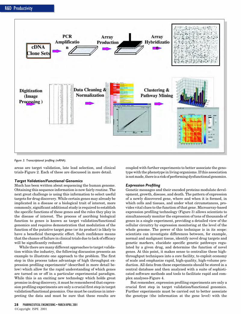
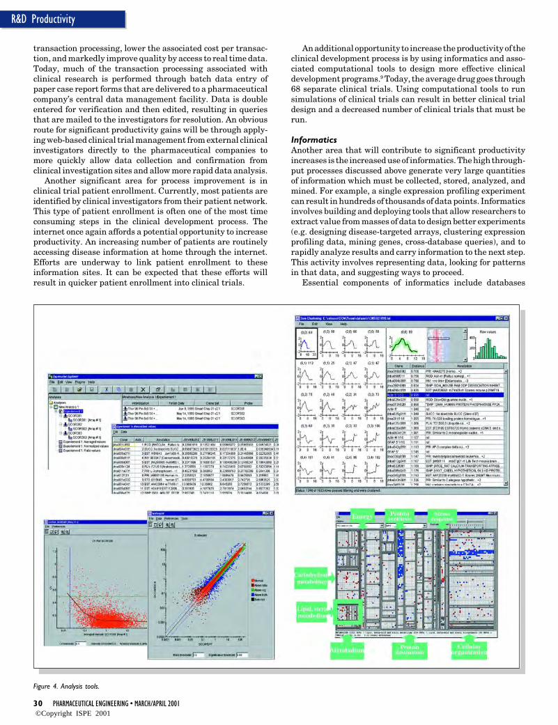
Expression ProfilingGenetic messages and their encoded proteins modulate devel-opment, growth, disease, and death. The pattern of expressionof a newly discovered gene, where and when it is formed, inwhich cells and tissues, and under what circumstances, pro-vides vital clues to the function of that gene. Microarray-basedexpression profiling technology (Figure 3) allows scientists tosimultaneously monitor the expression of tens of thousands ofgenes in a single experiment, providing a detailed view of thecellular circuitry by expression monitoring at the level of thewhole genome. The power of this technique is in its scope:scientists can investigate differences between, for example,normal and malignant tissue, identify novel drug targets andgenetic markers, elucidate specific genetic pathways regu-lated by a given drug, and determine the function of novelgenes. At this point, it makes sense to centralize these high-throughput techniques into a core facility, to exploit economyof scale and emphasize rapid, high-quality, high-volume pro-duction. All data from these experiments should be stored in acentral database and then analyzed with a suite of sophisti-cated software methods and tools to facilitate rapid and com-plex analyses-Figure 4.
But remember, expression profiling experiments are only acrucial first step in target validation/functional genomics.Further experiments must be carried out to better associatethe genotype (the information at the gene level) with the
phenotype (what we observe with our eyes) in living organisms.This requires the capability to examine gene expression inappropriate animal and cellular models. A number of technolo-gies are employed in these biological systems in order to up- ordown-regulate a specific gene or gene product to determinewhether or not a therapeutic effect can be achieved. For example,increasing the functional activity of a gene can be achieved byover-expressing a gene of interest in either a cell culture systemor a whole animal. To over-express the gene, additional copiesof that gene may be added to the DNA of the model cell systemor animal model through the use of techniques such as plasmidDNA vectors, DNA injection, and retroviral vectors. Scientistscan analyze the effects of over-expression of a gene in cell culturesystems to elucidate the cellular role of a gene product; simi-larly, they can analyze the more complex, physiological effectsof overexpression in transgenic mice.
Alternatively, the role of a gene can be elucidated by decreas-ing the functional activity of a gene (gene knock-down) or entirelyremoving the gene (gene knockout) from a cell or animal. Meth-ods of reducing gene expression in cell culture systems includethe use of antisense technology to decrease the formation of aspecific gene, as well as the use of antibodies which inhibitfunction by binding to the protein of interest. In animal models,gene knock-out/knock-down models are created by knocking outthe gene in embryonic cells to create whole animal models, byaltering the on/off switch which regulates the expression of thegene at later stages of development, or by introducing addi-tional copies of a gene containing different regulatory sequencesto turn the gene on and off in very specific time frames or tissuetype. Observation of changes in development, viability, behav-ior, and life span of these animals frequently provide importantclues as to the gene’s function and its role in complex diseaseprocesses. By using these animal models in high throughputscreening assays, it is possible to identify potential drug com-pounds rapidly and cost-effectively. These biological systemsand tools allow scientists to discover and investigate novelgenes and their function in multiple disease processes. Inaddition, careful analysis of the results from this series ofexperiments help scientists in selecting those targets whichshould have the best chance of success in modulating disease inhuman clinical trials.
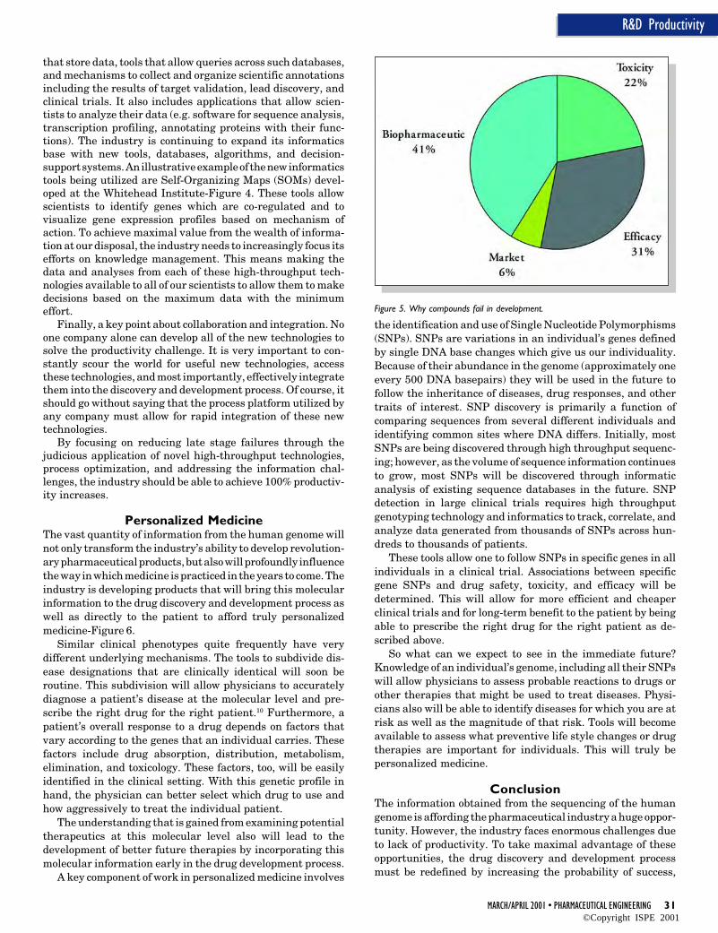
Late Lead SelectionIn the process used by most of the industry today, a novelbiological target is used to identify a compound that potentlymodulates that target. The structure of that compound is thenmodified to optimize the potency against that target. The nextstep is to further modify the structure of the compound toafford suitable properties for drug development. These proper-ties include desirable absorption, metabolism, and toxicityproperties (traditionally referred to as ADMET for absorption,distribution, metabolism, excretion, and toxicology). Manydrug candidates fail in the latter stages of this process becausea suitable structure can not be identified that simultaneouslypossesses all the desired properties.7 In fact, 41% of drugs failbecause of poor biopharmaceutical properties (stability, solu-bility, membrane permeability, metabolic liability, efflux, pro-tein binding, etc). An additional 22% of drugs fail because theyare toxic- Figure 5. Many of the technologies developed as partof the genomics revolution such as high throughput analyticalprocesses, high volume expression profiling, and proteomics(the study of protein content) can be utilized to assess theseproperties early in a compound’s development. Industry efforts
to deliver the tools to build accurate in vitro surrogate measuresof ADMET characteristics and associated computational meth-ods should allow us to reduce the failure rate significantly or atleast identify these failures much earlier in the process. Thesemethods when incorporated into an automated industrializedprocess should significantly improve a compound’s clinical trialsuccess rate and reduce the overall costs.
Clinical TrialsIn the area of clinical trials, there are two very large opportu-nities for productivity increases. The first is in the selection ofpatients for clinical trials; selection of patients that will opti-mize the chance of a successful outcome of the trial itself. Thisarea will be discussed in more detail in the PersonalizedMedicine section. The second area is in optimizing the processof clinical trial design and management. This will be discussedmore fully in the Process Optimization section which follows.
Process OptimizationNow, how can the 20% cost reduction be achieved for thesuccessful drug mentioned earlier. The industry needs to applythe concept of process optimization across the entire gene-to-patient continuum. A very important question that the industrymust consider is “can the pharmaceutical industry learn somelessons from traditional manufacturing companies?” The an-swer is clearly “yes.” This means studying the discovery anddevelopment process from the perspective of a process engineer;the entire gene-to-patient process as a unified process wheregenes go in at the beginning and drugs come out at the end. Bystudying the process as one single piece, one can achieve a muchgreater understanding of where to best make process improve-ments. One must realize that just because you can carry out aspecific assay faster doesn’t mean you’ll improve the wholeprocess. One must identify bottlenecks and predict the expectedeffect of applying technologies such as automation to thesebottlenecks. The next step is matching product flows through-out the pipeline so that resources are appropriately allocated.Finally, couple these predictive tools with a measurementsystem. This entire system lets employees ask how a potentialimprovement to the process will affect the entire process. Thenwhen these improvements are carried out the scientist has thetools to see if the prediction was correct. This affords the abilityto make constant real-time adjustments to productivity im-provements.
Two possible initial focus areas: The first is supply chainmanagement and the other is the clinical trial process. Typi-cally, when a scientist plans an experiment they determinewhat reagents they’ll need, order them, and then wait. If scienceis being done on an industrial scale then why not set up just-in-time supply of reagents. That way, as a drug progresses throughthe process the purchase order has already been placed auto-matically with the supplier and the experiment can be doneimmediately. Couple this effort with better design of experi-ments and better decision processes (which are the reallycrucial experiments that lead to the decision to proceed or killa project) and the productivity enhancements can be dramatic.
A key area that is ripe for process improvements is clinicaltrials. Traditional clinical research processes are time con-suming and costly, representing the majority of time and costin the drug discovery and development process.
There is an enormous opportunity to move the clinicaldevelopment process from a primarily paper based system toan electronic research system8 which will streamline research
transaction processing, lower the associated cost per transac-tion, and markedly improve quality by access to real time data.Today, much of the transaction processing associated withclinical research is performed through batch data entry ofpaper case report forms that are delivered to a pharmaceuticalcompany’s central data management facility. Data is doubleentered for verification and then edited, resulting in queriesthat are mailed to the investigators for resolution. An obviousroute for significant productivity gains will be through apply-ing web-based clinical trial management from external clinicalinvestigators directly to the pharmaceutical companies tomore quickly allow data collection and confirmation fromclinical investigation sites and allow more rapid data analysis.
Another significant area for process improvement is inclinical trial patient enrollment. Currently, most patients areidentified by clinical investigators from their patient network.This type of patient enrollment is often one of the most timeconsuming steps in the clinical development process. Theinternet once again affords a potential opportunity to increaseproductivity. An increasing number of patients are routinelyaccessing disease information at home through the internet.Efforts are underway to link patient enrollment to theseinformation sites. It can be expected that these efforts willresult in quicker patient enrollment into clinical trials.
An additional opportunity to increase the productivity of theclinical development process is by using informatics and asso-ciated computational tools to design more effective clinicaldevelopment programs.9 Today, the average drug goes through68 separate clinical trials. Using computational tools to runsimulations of clinical trials can result in better clinical trialdesign and a decreased number of clinical trials that must berun.
InformaticsAnother area that will contribute to significant productivityincreases is the increased use of informatics. The high through-put processes discussed above generate very large quantitiesof information which must be collected, stored, analyzed, andmined. For example, a single expression profiling experimentcan result in hundreds of thousands of data points. Informaticsinvolves building and deploying tools that allow researchers toextract value from masses of data to design better experiments(e.g. designing disease-targeted arrays, clustering expressionprofiling data, mining genes, cross-database queries), and torapidly analyze results and carry information to the next step.This activity involves representing data, looking for patternsin that data, and suggesting ways to proceed.
Essential components of informatics include databases
that store data, tools that allow queries across such databases,and mechanisms to collect and organize scientific annotationsincluding the results of target validation, lead discovery, andclinical trials. It also includes applications that allow scien-tists to analyze their data (e.g. software for sequence analysis,transcription profiling, annotating proteins with their func-tions). The industry is continuing to expand its informaticsbase with new tools, databases, algorithms, and decision-support systems. An illustrative example of the new informaticstools being utilized are Self-Organizing Maps (SOMs) devel-oped at the Whitehead Institute-Figure 4. These tools allowscientists to identify genes which are co-regulated and tovisualize gene expression profiles based on mechanism ofaction. To achieve maximal value from the wealth of informa-tion at our disposal, the industry needs to increasingly focus itsefforts on knowledge management. This means making thedata and analyses from each of these high-throughput tech-nologies available to all of our scientists to allow them to makedecisions based on the maximum data with the minimumeffort.
Finally, a key point about collaboration and integration. Noone company alone can develop all of the new technologies tosolve the productivity challenge. It is very important to con-stantly scour the world for useful new technologies, accessthese technologies, and most importantly, effectively integratethem into the discovery and development process. Of course, itshould go without saying that the process platform utilized byany company must allow for rapid integration of these newtechnologies.
By focusing on reducing late stage failures through thejudicious application of novel high-throughput technologies,process optimization, and addressing the information chal-lenges, the industry should be able to achieve 100% productiv-ity increases.
Personalized MedicineThe vast quantity of information from the human genome willnot only transform the industry’s ability to develop revolution-ary pharmaceutical products, but also will profoundly influencethe way in which medicine is practiced in the years to come. Theindustry is developing products that will bring this molecularinformation to the drug discovery and development process aswell as directly to the patient to afford truly personalizedmedicine-Figure 6.
Similar clinical phenotypes quite frequently have verydifferent underlying mechanisms. The tools to subdivide dis-ease designations that are clinically identical will soon beroutine. This subdivision will allow physicians to accuratelydiagnose a patient’s disease at the molecular level and pre-scribe the right drug for the right patient.10 Furthermore, apatient’s overall response to a drug depends on factors thatvary according to the genes that an individual carries. Thesefactors include drug absorption, distribution, metabolism,elimination, and toxicology. These factors, too, will be easilyidentified in the clinical setting. With this genetic profile inhand, the physician can better select which drug to use andhow aggressively to treat the individual patient.
The understanding that is gained from examining potentialtherapeutics at this molecular level also will lead to thedevelopment of better future therapies by incorporating thismolecular information early in the drug development process.
A key component of work in personalized medicine involves
the identification and use of Single Nucleotide Polymorphisms(SNPs). SNPs are variations in an individual’s genes definedby single DNA base changes which give us our individuality.Because of their abundance in the genome (approximately oneevery 500 DNA basepairs) they will be used in the future tofollow the inheritance of diseases, drug responses, and othertraits of interest. SNP discovery is primarily a function ofcomparing sequences from several different individuals andidentifying common sites where DNA differs. Initially, mostSNPs are being discovered through high throughput sequenc-ing; however, as the volume of sequence information continuesto grow, most SNPs will be discovered through informaticanalysis of existing sequence databases in the future. SNPdetection in large clinical trials requires high throughputgenotyping technology and informatics to track, correlate, andanalyze data generated from thousands of SNPs across hun-dreds to thousands of patients.
These tools allow one to follow SNPs in specific genes in allindividuals in a clinical trial. Associations between specificgene SNPs and drug safety, toxicity, and efficacy will bedetermined. This will allow for more efficient and cheaperclinical trials and for long-term benefit to the patient by beingable to prescribe the right drug for the right patient as de-scribed above.
So what can we expect to see in the immediate future?Knowledge of an individual’s genome, including all their SNPswill allow physicians to assess probable reactions to drugs orother therapies that might be used to treat diseases. Physi-cians also will be able to identify diseases for which you are atrisk as well as the magnitude of that risk. Tools will becomeavailable to assess what preventive life style changes or drugtherapies are important for individuals. This will truly bepersonalized medicine.
ConclusionThe information obtained from the sequencing of the humangenome is affording the pharmaceutical industry a huge oppor-tunity. However, the industry faces enormous challenges dueto lack of productivity. To take maximal advantage of theseopportunities, the drug discovery and development processmust be redefined by increasing the probability of success,
reducing the time to market, and introducing truly personalizedmedicine. These approaches will fuel future innovation andultimately change the current practice of medicine.
References1. Arlington, S., et al, Pharma 2005: An Industrial Revolution
in R&D, PriceWaterhouseCoopers, 1998, pg 6.
2. www.pharma.org.
3. Drews, J., Strategic Choices Facing the PharmaceuticalIndustry: A Case for Innovation, Drug Discovery Today,1997, 2:72-8.
4. Drews, J., Innovation Deficit Revisited: Reflections on theProductivity of Pharmaceutical R&D, Drug DiscoveryToday, 1998, 3:491-4.
5. Abelson, P.H., Improvements in Healthcare, Science, 1993,260:11.
6. Ramsay, G., DNA Chips: State-of-the-Art, Nature Bio-technology, 1998, 16:40-44.
7. Kennedy, T., Managing the Drug Discovery/DevelopmentInterface, Drug Discovery Today, 1997, 2:436-44.
8. Dvorin, J., Clinical Trials: Eliminating the Paper Chase, In-Vivo, Windhover Information, Inc., December 1999, 47-56.
9. Dvorin, J., A Virtual Way to Design Clinical Trials, Start-Up, Windhover Information, Inc., September 1999, 1-8.
About the AuthorMichael R. Pavia, PhD, is Chief Technology Officer atMillennium Pharmaceuticals, Inc. Dr. Pavia was a pioneer inthe field of combinatorial chemistry and brings more than 15years of experience in pharmaceutical research and discoveryto Millennium. He was formerly vice president-CambridgeResearch at Sphinx Pharmaceuticals, a division of Eli Lilly &Co. Prior to Sphinx, Dr. Pavia was vice president of chemistryat Genesis Pharmaceuticals and he held senior scientific posi-tions in the Department of Chemistry at the Parke-DavisPharmaceutical Research Division of Warner-Lambert. Heholds a BS in chemistry from Lehigh University and a PhD inorganic chemistry from the University of Pennsylvania.
Millennium Pharmaceuticals, Inc., 640 Memorial Drive,Cambridge, MA 02139.
Economic and Reliable PowerSources for PharmaceuticalFacilities
Economic and Reliable PowerSources for PharmaceuticalFacilities
U
by Joseph F. Maida, PE
This articledescribes thehistory of theelectrical utilityindustryderegulation andthe changes thathave taken placewithin theindustry thatdirectly relate topharmaceuticalfacilities. Itdiscusses changesin the NationalElectrical Codethat will affectthe reliability ofthe electricaldistributionsystems in thepharmaceuticalfacility.
Introduction
U nderstanding how electricity gets fromits point of origin to its point of usealong with the history of the regula-
tion and deregulation of the electrical utilityindustry will aid pharmaceutical companies inevaluating how to purchase and distribute elec-tricity in their facilities. Because of governmen-tal deregulation on the national and state level,electrical power, which was once taken forgranted, is now being bought and sold like acommodity. With this, new codes adopted as lawby every local governmental body in the countrycontinue to change how electricity can be dis-tributed within pharmaceutical facilities. Un-derstanding the power sources that exist withinpharmaceutical facilities and the laws that af-fect these sources will assist pharmaceuticalcompanies as they expand their electrical dis-tribution systems and as they prepare for lessreliable utility electrical power in the future.This article will begin by looking at the historyof the electric utility industry and its evolutionfrom a deregulated, to a regulated, and back toa deregulated industry over the last 100 years.
History of Deregulation in the 1980sPharmaceutical facilities will need moreeconomical and reliable electrical poweras the industry continues to grow. Thisneed will only increase as people live longer,thanks in part to the development of new andbetter drugs by the pharmaceutical industry.What was, only 20 years ago, a much smallerindustry, today the pharmaceutical industry isone of, if not, the largest industry in certainareas of the US. In southeastern Pennsylvania,the pharmaceutical industry has replaced olderindustries, such as steel and manufacturing,that have left the area in part due to the highcost of electricity.
When President Carter signed the PublicUtility Regulatory Policies Act (PURPA) of 1978,the pharmaceutical industry’s demand for elec-tricity was small compared to the demand for
electricity from older industries. As these olderindustries left southeastern Pennsylvania, thepharmaceutical industry was able to expandand reap the benefits these industries left be-hind. These benefits included a highly educatedwork force, many of the best universities in thecountry, and a political atmosphere that wantedto deregulate industries with the goal of lower-ing prices.
In addition to lower prices, President Carterwanted a cleaner environment. He believedthat the deregulation of a number of industrieswould help our nation achieve both of theseobjectives.1 During his four years in office, Presi-dent Carter deregulated the airline and naturalgas industries and laid the groundwork for thederegulation of the electrical utility and tele-communications industries. His policies led tolower prices for electricty and the developmentof technologies for cleaner sources of electricity.However, with deregulation, incentives, whichexisted within a regulated industry and causedthe utility companies to invest in new powerplants, would be lost. As a result, utility sourcesof electricity are and will continue to becomeless reliable.
PURPA required utility companies to pur-chase power from “qualifying facilities” thatproduced electricity as a by-product of otheractivities.2 Qualifying facilities included largeindustrial plants that built co-generation sys-tems. A co-generation system has a steam or gasturbine that is connected to a generator thatproduces electricity. The waste steam from thesteam turbine or the heat generated by the gasturbine is used for processes within the facilityor for heating the facility. Because of the effi-cient use of the fuel, co-generation systems arebetter for the environment than utility powergenerating systems that do not use their wastehest. By using the waste hest, the cost of produc-ing electrical power by these qualifying facili-ties was less than the cost of their buyingelectricity from the electrical utility company.Some of the qualifying facilities burn waste
material from the facility’s process or even trash, adding to theirefficiency. Also, when the qualifying facility generated moreelectricity than it could use, the electrical utility was requiredto buy back this excess electricity. Sometimes, this was at aprice higher than the price the utility could buy electricity forfrom other utility companies.
PURPA changed the generation, transmission, and distri-bution of electricity in this country, maybe forever. During theProgressive Era from 1896 to the start of World War I, utilitycompanies were formed as a result of the government trying toregulate the generation, transmission, and distribution ofelectricity. Prior to the progressive era, small generatingplants were built in urban areas of the country to serveresidents and businesses in the local area. The governmentwanted the power companies to expand their distribution tolarger and more rural areas. The invention of the transformerin 1885 made this possible. Transformers raise the voltage ofthe generated electricity to levels that will conduct largeamounts of power at lower currents, thus permitting the use ofsmaller wires, referred to as high voltage transmission lines.Because of governments’ interventions, the utility industryevolved into a monopoly that included a limited number ofregulated companies. As a regulated monopoly, utility compa-nies did not lose money on projects that had negative returns.Utility companies owned all parts of the electrical utilityindustry including the generation, transmission, and distribu-tion. Their prices for electricity, although monitored by publicutility commissions, could be raised high enough to alwaysexceed their costs and essentially guarantee them a profit.New developments and innovations were shared by the utilitycompanies through organizations like the Electric Power Re-search Group that was formed in 1972.
The 1980s saw the birth of high technology industries thatemerged as a result of the invention of the personal computerin 1978. Together, the pharmaceutical and high technologyindustries are the foundation for the industrial expansion inthis country today. They are also the targets for future govern-ment regulations. Without the government telling these in-dustries where and how to expand their businesses, the phar-maceutical and high technology industries have expandedtremendously and are directly or indirectly responsible formuch of the continuing demand for more reliable and economi-cal electrical power. These expansions were not envisioned in1978 when many politicians believed that the demand forelectricity would decrease as new technological advances weredeveloped, thus driving down the price of electricity.
History of Deregulation in the 1990sTechnical innovations and changes in governmental policies ofthe 1990s resulted in the development of alternative sources ofelectrical power and the restructuring of the electrical utilityindustry in many states. Gas turbine technology was enhancedbecause of the lower cost of natural gas, a result of thederegulation of the natural gas industry. Gas turbines wereconnected to generators to produce electricity as part of a co-generation system or to run for short periods of time to satisfydaily peak electrical loads, a process referred to as peakshaving. Electric bills for pharmaceutical facilities typicallyinclude a usage charge and a demand charge. The usage chargeis determined by multiplying the actual kilowatt-hours con-sumed by the price per kilowatt-hour. A kilowatt-hour is equalto the average amount of real electrical power, measured inwatts, times 1000, times the period of time during which the
average is measured. The demand charge is an additionalcharge added to all electrical invoices for a period (typically oneyear) based on the highest average kilowatt demand over adefined period of time, typically 15 minutes, which occursanytime during the period. Therefore, a facility that has a peakelectrical demand in the summer for air conditioning will paya demand charge based on that peak demand for the nexttwelve months. Installation of a peak shaving generator setenables a facility to avoid excessive demand charges.
Other alternative methods for generating and saving elec-trical power were enhanced and explored as viable options tousing fossil or nuclear fuel to generate electricity. Theseincluded windmills, geothermal, hydroelectric, and solar cells.In addition, as an alternative source for generating electricity,absorption chillers that use steam versus electricity to createchilled water for air conditioning systems, and ice storagesystems that would create ice during the night and use itduring the day for cooling, are forms of peak shaving. Theseinnovations and the passage of the Energy Policy Act of 1992under President Bush, got the attention of the electrical utilityindustry. Reacting to these, utility companies began to developnew rate schedules to reduce the electrical bills for their largeindustrial companies.
The Energy Policy Act of 1992 permitted utility companiesto sell electricity anywhere in the country using transmissionlines owned by other utility companies, a process that becamereferred to as “wheeling.” Fearing that their customers wouldpurchase power from other utility companies, the utility com-panies created the electrical curtailment rider. PECO, anelectrical utility company in southeastern Pennsylvania, pro-vided an incentive that reduced electrical bills for customerswith a demand above 10,000 KW by as much as 50% if thecustomer reduced its maximum power demand to 25KW or lesswith 30 minutes notice. Many large facilities took advantage ofthis rider. Some companies could suspend manufacturing andsend their personnel home and still save money because of the
Figure 1. One of many building management system screens used to operate andmonitor a 10.6 MW on-site power generating system in a pharmaceutical researchfacility for electrical curtailment.
savings afforded to them by the new curtailment rates. Pharma-ceutical plants and research facilities could not suspend theirresearch or manufacturing and found other ways to meet thisrequirement. They installed new on-site generator sets thatcould carry their load during the 10 to 12 hour period they wererequired to use less than 25 KW of utility power. Doing this, onepharmaceutical research facility in southeastern Pennsylvaniasaved $14,000,000 on their electrical bills over a five-yearperiod. Their investment of $3,000,000 that added diesel en-gine generator sets and controls to their on-site emergencypower diesel engine generators also increased their on-siteemergency and standby power generating capacity to 10.6 MW.This proved to be a valuable resource even after their initialcurtailment contract ended. New power companies wantedtheir business and possibly their on-site generating capacity asa result of deregulation.
Deregulation TodayAs the 1990s came to a close, 23 states and the District ofColumbia, led by California on April 1, 1998, took the next stepin the deregulation of the electrical utility industry. They didthis by restructuring the electrical utility industry in theirstate. Restructuring enabled electrical power companies, otherthan the local utility company, to sell electricity in the retail,consumer market. The local utility company would no longercontrol, and in some cases no longer own the electrical genera-tion in their distribution area. In California, utility companieswere forced to sell their generating plants. Utility companiescontinue to own the transmission and distribution lines andequipment in their area. Now the consumer could choose to buyelectrical power from the power company that offers the lowestprice and to pay the utility company for the use of theirtransmission and distribution lines.
Twenty of the remaining 27 states are in the process ofinvestigating or enacting restructuring laws.3 The seven statesthat have not enacted restructuring laws already have lowrates for electricity. Deregulation also has affected these statesby reducing their competitive edge over states that otherwisewould have higher rates than they have now. Also, as would bedemonstrated in June 1998, the price of electricity wouldincrease for all states when the demand exceeds the supply.Many electrical utility companies and other newlyformed power companies have become brokers that buyand sell electricity like a commodity. Will the supply anddemand of electricity affect the availability of economicalreliable electricity in the future? Now that utility companieshave less incentive to build new plants, will new power compa-nies or technologies be able to fill the demand for new electric-ity?
Pharmaceutical facilities, most of which are in states thathave passed restructuring legislation and have high prices forelectricity, can now choose the power company from whom theywant to buy electrical power. Buying electricity from a powercompany other than the local electrical utility has reduced andmay continue to reduce the cost of electrical power for largeusers of electrical power. In some cases, as mentioned above,power companies will provide special rate structures to facili-ties that have on-site generators and are willing to and capableof selling electricity back to the power company. The complex-ity of requiring two companies, the power generating companyand the local utility company, to obtain electricity has de-creased and will continue to decrease the reliability of electri-cal power sources in our nation. The electric power distribution
Figure 2. Circuit breaker switches, generator control switches and pushbuttons,indicator lamps, and meters used to manually parallel seven on-site generators to autility line, to transfer load to and from the utility line, and to monitor generator andutility line loads.
system within the pharmaceutical facility also has becomemore complex. It too will become less reliable if it is notmaintained and expanded properly as a facility’s demand forelectricity increases.
New Codes and RegulationsIn the interest of safeguarding the public, local governmentsregulate how electricity is distributed within the pharmaceu-tical facility. They do this by adopting the National ElectricalCode (NEC) as the minimum requirement for the installation
of electrical distribution systems within buildings and facili-ties within their jurisdictions. When a new version of the NECis issued, the local authority having jurisdiction usually adoptsit within a short period of time. The National Fire ProtectionAssociation publishes the NEC every three years. The NECcovers everything from the installation of the primary highvoltage service cables and equipment for the facility to theinstallation of low voltage instrumentation and control cir-cuits.
Each new version of the NEC contains many changes andadditions. New electrical installations for new construction orremodels within existing facilities must comply with the latestversion of the code. Therefore, if a pharmaceutical companyremodels a section of their facility, the electrical power distri-bution system in the remodeled section and the power distri-bution system that provides power to that portion of the facilitymust be upgraded to comply with the latest code requirements.The cost for doing this could be significant, especially forfacilities that use on-site generators with non-dedicated auto-matic transfer switches for their egress lighting and exit signs.
Power Sources in Pharmaceutical FacilitiesChanges in the 1996 and 1999 NEC include new requirementsfor legally required emergency power distribution systems,fire pumps, low voltage instrumentation control circuits, aswell as many other items that will not be addressed by thisarticle. To comply with the new requirements, costly changesto facilities’ existing electrical power distribution system maybe necessary when building an addition or remodeling an area.To understand some of the new requirements, it is necessaryto be knowledgeable of the following sources of electrical powerthat can be found in a pharmaceutical facility.
• Normal Utility Power - Electricity obtained through thefacility’s main service entrance equipment that connectsthe facility to the utility’s normal power line.
• Reserve Utility Power - Electricity obtained through thefacility’s main service entrance equipment that connectsthe facility to the utility’s alternate power line. Sometimesboth the normal and alternate power lines supply power tothe facility at the same time in a Dual Service arrangement.These types of services are normally restricted to highvoltage services. High voltage service entrance equipmentusually has automatic circuit breakers and control relaysthat will transfer the facility load to an energized utilitypower line upon the loss of power on the other utility line.
• Legally Required Emergency Power - Electricity thatserves legally required emergency loads and must be presentwithin 10 seconds upon loss of normal utility power. Legallyrequired emergency loads are defined within building codesand usually include emergency egress lighting and exitsigns. The electricity can be obtained from a separate utilitypower line or can be generated on-site using emergencygenerator sets or batteries. Emergency generator sets musthave on-site fuel sources, dedicated Automatic TransferSwitches (ATS), and dedicated power distribution equip-ment and circuits. Variances for use of natural gas may beobtained from the authority having jurisdiction.
• Legally Required Standby Power - Electricity thatserves legally required standby loads and must be present
within 60 seconds upon loss of normal utility power. Legallyrequired standby loads are defined within building codesand include “heating and refrigeration systems, communi-cations systems, ventilation and smoke removal systems,sewerage disposal, lighting systems, and industrial pro-cesses, that, when stopped during any interruption of thenormal electrical supply, could create hazards or hamperrescue or fire-fighting.”4 The electricity can be obtainedfrom a separate utility power line or can be generated on-site using emergency generator sets or batteries. Standbygenerator sets require on-site fuel sources but do not re-quire dedicated Automatic Transfer Switches (ATS) anddedicated power distribution equipment and circuits.
• Optional Standby Power - Similar to Legally RequiredStandby Power, except that the loads are selected by thefacility and include critical systems and equipment withinthe facility.
Small pharmaceutical plants as well as administrative officesmay not have a reserve utility power source, a legally requiredstandby power source or an optional standby power source.Facilities that decide to install an additional ATS to complywith the new NEC requirements may need to replace theirexisting ATS as well. Whenever more than one ATS is installedon a power distribution system, it is sometimes necessary toswitch the neutral conductor in addition to the three phaseconductors.5
Reliability of Power within thePharmaceutical Facility
The reliability of normal and reserve (alternate) utility powerlines in most major metropolitan areas has been very high.Concurrent power failures on both utility power lines couldhave happened once every five years before restructuring. Inthe future, with the utility companies having fewer incentivesto increase existing or continue to own power generatingcapacity, power failures of both sources might occur moreoften. On-site optional standby power generating sys-tems will become an increasingly essential part of apharmaceutical facility’s infrastructure.
Many pharmaceutical facilities built prior to 1996, in-stalled on-site power generating capacity for all or a significantportion of the load within their entire facilities. Others addedadditional electrical power generating capacity to enable themto take advantage of electrical power price incentives offeredby the public utilities. Common automatic transfer switcheswere installed to transfer power from the public utility to theon-site diesel or gas powered generator sets upon loss of utilitypower. The 1996 NEC requirement for dedicated automatictransfer switches for new legally required emergency loads, inmany cases, makes the use of the existing emergency genera-tors unfeasible for legally required emergency loads. Newgenerators or other sources of legally required emergencypower are required.
Generally, emergency egress lighting fixtures and exitsigns with internal batteries (unit equipment) or centrallylocated storage batteries or uninterruptible power suppliescan be used in lieu of on-site generators to satisfy building codeand NEC requirements for legally required emergency sys-tems. Unit equipment is very reliable, but has a high mainte-nance cost. Unit equipment is typically designed to operate for1.5 hours, the minimum time allowed by the NEC. Unit
Figure 3. 1,600 Kilowatt and a 1,400 Kilowatt (background) - 13,200 Volt, 3phase diesel engine emergency generator set.
equipment has an advantage over other types of emergencypower equipment because unit equipment will detect the lossof power at point of use and provide almost immediate illumi-nation to the affected area. An area can lose power because ofa failure to the electrical circuit feeding the area. This is onereason why the NEC requires that all electrical circuits, andnow even the ATS that serve legally required emergency loads,be dedicated and separated from the normal power distribu-tion circuits.
On-Site GeneratorsGenerators are available in many sizes and voltages and withengines that can run on one or even two types of fuel. For bothlegally required emergency and standby loads, generator setsthat use internal combustion engines as their prime movermust be provided with an on-premise fuel supply sufficient fornot less than two hours of operation at full load. Sizing agenerator for a specific building or specific loads is fairlysimple. Computer programs are available to aid in this effort.As the number of on-site generators increases within a facility,the amount of excess or contingent power that could be used ifit could be distributed to other parts of the facility becomes aconsideration. Also, as a facility grows or changes, the locationof local generators or the space available to install new localgenerators often presents a problem. The installation of cen-tral generator sets with priority load shedding can eliminatethis problem. This approach also will reduce the amount ofunusable excess or contingent generator capacity that is in-stalled within the facility. The generator sets, if not intendedto operate for weeks at a time,6 can have standby rated enginesversus prime rated engines. They also can be loaded to theirfull nameplate capacity. Generators that are intended to be theprime source of power, or intended to operate in parallel withthe normal utility power source continuously, should be primerated.
A major disadvantage of having only a central power gener-ating system is that the system cannot provide power toselective loads that lose power due to a failure in the facility’spower distribution system. This potential problem can begreatly reduced by installing a redundant power distributionsystem. Problems within the system that occur at the locallevels require much less time to repair than a problem withinthe main facility power distribution system (e.g. the replace-ment of a main distribution transformer versus a local lightingtransformer). Another way to prepare for a local failure is tomake provisions for the temporary connection of a portablegenerator that usually can be rented quickly. A portablegenerator can be used for non-legally required standby loads.It also can be used as the backup to the normal emergencygenerator. The normal emergency generator must have abackup when it is out of service for more than a few hours formaintenance.7
Large pharmaceutical facilities should consider having twoutility power sources, redundant primary voltage feeders andtransformers, and a combination of centrally located, primaryvoltage emergency generators with some smaller, utilizationvoltage, local emergency generation for legally required emer-gency loads and some legally required and critical standbyemergency loads. Smaller pharmaceutical facilities also shouldconsider having two utility power sources, one at a primaryvoltage level (above 12KV), and one at a utilization voltagelevel (480V or 208V) with a central emergency generator atutilization voltage that can be used for emergency and standby
loads. In many cases, the power companies will not provide theprimary service because the facility load is below their require-ments for this type of service.
Each pharmaceutical facility must evaluate their require-ments with the cooperation of the local utility company. Beforea utility company will permit a facility to connect their on-sitegenerators in parallel with the utility’s supply line, protectiverelaying and sometimes grounding transformers will need to beinstalled. The engineering and design for systems that operatein parallel can be quite significant, but is necessary to safeguardother utility customers that may be connected to the samesupply line as the pharmaceutical facility.
Automatic selective load pickup and load shedding is neededto ensure adequate power to (1) the emergency circuits, (2) thelegally required standby circuits, and (3) the optional standbycircuits, in that order of priority. Electrically operated circuitbreakers controlled by a programmable logic controller or areliable building management system combined with two ormore generator sets provides a reliable source of emergencypower.
Fire PumpsWhen designing a new power distribution system or adding anew building that requires an electric fire pump, the require-ments for providing both normal and emergency power to thefire pump must be considered. The NEC does not require thata fire pump be on emergency power if the electric utility serviceis reliable. Public utility companies have however, mandatedthat their power line not be the only source of electric power toa fire pump. In most cases, fire pumps would be a part of thefacility’s legally required emergency load. Because the firepump will normally be rated at utilization voltage (480 Volts)and not primary voltage and because it requires a separateservice or must be connected ahead of the main service en-trance equipment, the provision of a second, utilization voltageservice has some advantage. It eliminates the cost for adedicated transformer when a primary service is installed.
Consideration for Future Expansion:Many pharmaceutical facilities will need to modifytheir existing normal and emergency power systems to
Figure 4. Protective relays, control relays, synchronization controller and loadtransfer controllers used to parallel a pharmaceutical facility’s generators with theutility supply line.
meet future power demands. Decisions relative to futurerequirements for emergency power will depend on the type offacility (research, manufacturing, or administrative). It alsowill depend on the financial impact that could result from theloss of power (e.g. the loss of a research project) and onmanagement’s philosophy. These decisions have always beencomplex and are now even more intricate. A thorough under-standing of the present and future normal and emergency powersystem and the complexities of how the power systems can beexpanded in the future will enable the plant engineer to increasethe reliability of the facility’s power system. It also will createan overall awareness of the significant hidden cost that shouldbe part of any analysis of the facility’s future capital expendi-ture plans.
Instrument and Control Power SuppliesWhen evaluating new designs and installations, the pharma-ceutical industry should not forget their low voltage instru-mentation and control systems and the NEC requirements fortheir power supplies. The requirements for these also havechanged with the adoption of the 1996 NEC. Prior to 1996NEC, a 12 Volt DC power supply rated above 100 watts couldbe used for instrumentation and control systems that hadcables and wires rated below 600 volts and in sizes smallerthan #18 gauge as long as the wires were fused. Since the 1996NEC, the 12 volt power supply for this type of cable or wiremust be UL Listed or Labeled as a Class 2 power supply,whether the wires are fused or not.8 What seems to makeperfect sense, using a 300 volt cable for a 12 volt circuit, maynow violate the NEC because this type of cable can no longerbe used with the non-Class 2 power supply that was commonlyinstalled on most instrument and control circuits prior to 1996.
Be AwarePharmaceutical facility managers and plant engineers mustbe aware of new requirements within codes as they expand andadd new loads to their facilities. They also should be aware ofopportunities to obtain alternate sources of economic andreliable electricity. The present and future cost of reliableelectrical power should be a part of any pharmaceutical facility’s
Strategic Corporate Plan. Knowing what happened to otherindustries, partly because of the loss of their competitive edgedue to the high cost of electricity, may assist the pharmaceu-tical industry in finding new reliable sources of economical andreliable electricity. Knowing what happened a few yearsago should strike more fear into the pharmaceuticalindustry’s risk managers than Y2K did last year.
Answer to QuestionsImagine what would happen if a residential customer receiveda $5,000 electric bill. This might have happened in June 1998had areas of the Midwest been deregulated. On June 25, 1998,the wholesale price for electricity in the Midwest went fromaverage prices of $25 to $40 per megawatt-hour (1,000 kilo-watt-hours) to a peak price of $7,500 per megawatt hour.Reportedly, Commonwealth Edison (Chicago) paid $4,000,000for $100,000 worth of electricity.9 Also on that day, at 11:00AM, the Pennsylvania New Jersey Maryland Interconnect(PJM), which incorporates all transmission lines in southeast-ern Pennsylvania, declared a “maximum emergency” anddiscontinued selling electricity to the Midwest. At the sametime they curtailed many of their large customers. Thesecustomers included a number of major pharmaceutical facili-ties. PJM was permitted to cut off power transactions with theMidwest because of destabilizing power flows in their system.This cut-off was in accordance with a recent ruling from theNorth American Electric Reliability Council (NERC). NERCwas established in the wake of the 1965 Northeast Blackoutthat was caused by instability in the PJM system. Also, as aresult of the June 1998 price surge, some newly formed powercompanies went out of business. Knowledge of the past preparesone for the future. To read more about this and other aspects ofderegulation go to Smithsonian Institution Powering a Genera-tion of Change Web Page at http://americanhistory.si.edu/csr/powering/.
Get Professional HelpThis article was written to assist PharmaceuticalEngineering’s readers in understanding today’s power sys-tems and their requirements. All statements contained hereinare believed to be accurate, but they are not intended to replacedesign standards or codes. Before using the information con-tained herein, the reader should refer to the latest versions ofapplicable codes and standards, or consult with a ProfessionalEngineer.
References1. Smithsonian Institute – Powering a Generation of Change
- http://americanhistory.si.edu/csr/powering/
2. Smithsonian Institute – Powering a Generation of Change- http://americanhistory.si.edu/csr/powering/
3. Energy Information Commission - http://www.eia.doe.gov/cneaf/electricity/chg_str/regmap.html
4. NFPA 70, NEC 1999 Edition - Footnote to Article 701-2.
5. ANSI/IEEE Std 446-1987 – Article 7.9.5.
6. IEEE Recommended Practices for Emergency and StandbyPower Systems – Std 446-1974.
7. NFPA 70 – 1999 NEC Handbook – Comment to Article 700-5.
8. NFPA 70 – 1999 NEC Article 725 – 41.
9. June 30, 1998 Energy Online Daily News.
About the AuthorJoseph F. Maida has a BS and an MS in electrical engineeringfrom Drexel University. He was a licensed electrical contrac-tor, an officer in the US Army Reserves, and an employee of twopublic utility companies and a consulting engineering firmprior to starting his own company in 1978. As president ofMaida Engineering, Inc. for the last 22 years, he has manageda multidiscipline engineering, design/build, and systems inte-gration firm that has worked in many large and small pharma-ceutical facilities He is a registered Professional Engineer in anumber of states and has consulted on, engineered, and over-seen the design and construction of power, control and instru-mentation systems throughout the US and overseas.
Maida Engineering, Inc., 550 Pinetown Rd., Suite 400, FortWashington, PA 19034.
Barrier Isolation History andTrends, A Millennium UpdateBarrier Isolation History andTrends, A Millennium Update
Tby Jack Lysfjord and Michael Porter
T his is an update from a 1998 survey onthe global trends on barrier isolationusage for automated (non-manual) fill
finish operations. The survey took place duringMarch-May 2000 and summarizes findings fromvendors and users. Data was first presented inJune 2000 at the ISPE Barrier Isolation Tech-nology Conference and updated in September of2000.
This survey showed an increase in number ofunits from 84 in the 1998 survey to 172 in 2000.Figure 1 shows the deliveries/year with thedotted vertical line indicating that 2001 and2002 deliveries are planned, but data can in-crease for these years depending on additionalorders. Over the past five years, global deliver-ies of barrier isolators have averaged 22/year.
Figure 2 breaks down the previous data intousage by continent. Europe has historicallybeen the leader over North America. Growth isoccurring in North America. Japan is beginningto use the technology and one unit appears inAfrica.
Figure 3 indicates companies that are com-mitted to this technology. The number of com-panies using the technology increased from 38in 1998 to 56 in 2000. The number of filling lines
reported in operation increased from 34 in 1998to 70 in September 2000. FDA approval in-creased from 6 to 26 in the same period. Thetime from delivery to start of operation is shownin Figure 4. Type of container and maximumspeed is shown in Figures 5 and 6.
Barrier isolator construction is continuing tobe dominated by hard wall designs (stainless/glass) with 134 versus 9 soft wall units. In 1998,the numbers were 73 and 9 respectively. Sur-rounding room classification results are shownin Figure 7 and sterilants used are shown inFigure 8.
Systems design of open barrier isolator (con-tinuous motion) is 83 versus closed (batch pro-cess) of 20. Figure 9 shows barrier isolatorpressure to surrounding room with Figure 10showing the pressure to the washer room foropen systems.
Containment is a growing need and utiliza-tion of barrier isolation for the containmentapplication is shown in Figure 11. Cumulativedeliveries of systems for fill/finish applicationsare shown in Figure 12.
Several questions on glove usage were askedto support a glove discussion at the June confer-ence. There is a preference for two piece gloves
(glove and sleeve) overone-piece glove/sleeveby 51/35 ratio. Smoothsleeves were preferredover pleated (accordionor bellows) sleeves by40/11 ratio. A seconddisposable glove is pre-ferred by 70/25 ratioover no second gloveand glove integritytests are typically per-formed by 72 where 23do not test. Methods ofintegrity testing areshown in Figure 13.Typical glove replace-ment periods areshown in Figure 14.Only 17 lines utilizehalf-suits. Preferencesbased on this surveyindicated:
Figure 1. Barrier isolator fillingline deliveries by year.
This articlesummarizessurvey resultstaken in thespring of 2000 onthe use of barrierisolators in fill/finish applicationsin the parenteralindustry.
For completesurvey raw data,log on to the ISPEWeb site -www.ispe.org.
The use of barrier isolation technology has shown significantgrowth over the past two years and is continuing to grow. Thesedata are presented to help show an important industry trendin parenteral fill/finish operations, a trend that should beconsidered by manufacturers of aseptically filled products.
Figure 13. Method for integrity testing of gloves (72 responses).
Figure 14. Glove replacement period (60 responses).
Figure 11. Barrier isolators indicating need for containment.
Yes 17
Chemical 12
Biological 2
Chemical Biological 1
Chemical Nuclear 2
No 76
Total 93
(BUGS). He is a frequent speaker and course leader in the US,Europe, and Asia, and has been author and co-author fornumerous technical papers and articles. He has served aschairman of ISPE’s annual Barrier Technology Conferences inthe US and Europe. Lysfjord holds a BS in mechanical/indus-trial engineering from the University of Minnesota and a MBAfrom the University of St. Thomas.
Michael Porter is a Senior Engineer in the Sterile ProcessTechnology Operations group of Merck & Co., Inc. Since 1987,he has held a variety of engineering and supervisory positionswithin Merck Manufacturing Division, focusing on manufac-turing, lyophilization, and barrier technology filling of vac-cines and sterile pharmaceuticals. Porter has prior experiencein plant and process design in the petrochemical industry andholds a BS in chemical engineering from Villanova University.He is a member of PDA and ISPE, and has presented on thesubject of cleanroom robotics and barrier technology morethan a dozen times to the pharmaceutical community.
Merck & Co., Inc., Sumneytown Pike, PO Box 4, WP38-12,West Point, PA 19486.
Figure 10. Pressure to washer room - Pascals (27 responses).
About the AuthorsJack Lysfjord was the ISPE Member of the Year in 1994. Heis the Chairman of the Marketing Advisory Council, pastchairman and member of the Vendor Committee, and cur-rently serves on the ISPE International Board of Directors.Lysfjord is Vice President of Technology and InternationalSales for Bosch Packaging Technology. His prior experiencewas with Dahlberg Inc., Litton Microwave Cooking Products,Medtronics, Inc., and Onan Corporation. He holds member-ships in the Lums Group and Barrier Users Group Symposium
This articleprovides a briefExecutiveSummary of theCommissioningand QualificationBaseline® Guide.
Introduction
T he first goal of the Commissioning andQualification Guide is to bring a com-mon terminology and methodology to
the commissioning and qualification processthat can be used by manufacturers, facilitydesigners, contractors, and equipment suppli-ers.
The Commissioning and Qualification Guidedefines systems in terms of their function andconsequent impact on product quality, whichdetermines the level of commissioning and quali-fication required.
• “Direct Impact” systems are expected tohave an impact on product quality
• “Indirect Impact” systems are not ex-pected to have an impact on product quality
Both types of systems will require commis-sioning. However, the “Direct Impact” systemswill be subject to supplementary qualificationpractices to meet the additional regulatoryrequirements of the FDA and other regulatoryauthorities.
The second goal of this Guide is to provide aSystem Impact Assessment process to bringstructure and consistency to determiningwhether a system is a “Direct Impact” system or“Indirect Impact” system.
This differentiation between system typewill determine the attention and effort given toeach and by whom. Therefore, the determina-
tion as to whether the system is “Direct” or“Indirect” impact is critical. System ImpactAssessment provides both the thought processand some key questions that must be asked inmaking the determination.
System Impact Assessment is an informedjudgment, made by a group of appropriatelyqualified stakeholders and should be based on acomprehensive understanding of the product,process, and the nature of the systems andcomponents. This decision should be justifiedand made explicit, in a concise manner, throughthe production of a QA-endorsed Impact As-sessment Rationale for each system.
The Impact Assessment Rationale for eachsystem should also document the componentcriticality assessment in a similar manner.
An interdisciplinary team approach to com-missioning and qualification will help establishan effective basis for master planning and ex-ecution of facility projects. Specifically, the Guideis focused upon value added approaches thatwill eliminate duplication of effort and the costlypractices of:
• repeating qualification steps during processvalidation
• qualifying systems that only require com-missioning
• generating insufficient or excessive docu-mentation
• Delays which can result in productsupply interruptions or delayed prod-uct launches
Guide Philosophy and KeyConcepts
This Chapter describes the purpose andphilosophy of the Commissioning andQualification Guide, and the differencesbetween the commissioning and quali-fication processes in the context of thisGuide. It is important to understandand apply the approaches outlined inthis Guide in a sound and well-rea-soned manner, since every facility andproject is different. The key terms usedin the Guide are defined, including:
• “Direct Impact” System
• “Indirect Impact” System
• “No Impact” System
• Design for Impact
• Good Engineering Practice
• Enhanced Design Review
• Commissioning
An overview of Qualification Practicesis given, including Enhanced DesignReview, Installation Qualification, Op-erational Qualification, and Perfor-mance Qualification. V-models are pro-vided for both “Direct Impact” systemsand “Indirect Impact” systems and therole of Quality Assurance is discussed.
Impact AssessmentImpact Assessment is the process ofdetermining which systems and/or sys-tem components should be subject toQualification Practices in addition toGood Engineering Practices (GEP).Impact Assessment assists in definingthe Commissioning and Qualificationscope of a project.
This Chapter considers the ImpactAssessment process. Terms specific toImpact Assessment are defined. Amethod is suggested for defining thesteps of a system assessment process,including a discussion of the benefits,and a list of the criteria for determiningsystem impact and component critical-ity.
Good Engineering PracticeThis Chapter provides an overview ofthe various project phases and sequence,from inception through commissioning,qualification, and operation. Conceptsassociated with “Good Engineering Prac-tice” (GEP), the types of activities thatoccur, and documentation that is cre-ated through GEP are discussed. Over-views are provided of both effectiveproject controls, and project team con-cepts and organization. The Require-ments phase is considered in detail,including:
• Project Purpose and Justification
• User Requirements Brief
• Requirements Specifications
• Project Execution Plan
• Maintenance and Technical SupportRequirements
• Compliance Requirements
• Deliverables
Stages in the design process are de-scribed with specific consideration ofPiping and Instrumentation Diagrams,Specifications, and Construction draw-ings. Construction involves several ele-ments, which are crucial to every project,including project site logistics andproject quality control. This Chapterdetails typical requirements and ele-ments of construction.
The information given in the Chap-ter aims to demonstrate how GEP, asapplied throughout the project lifecycle,provides a basis for effective qualifica-tion.
CommissioningThis Chapter defines the term “com-missioning” in the context of the Guideand describes the organization and con-tent of the Commissioning Plan docu-ment. Commissioning is positionedwithin the context of the Qualificationeffort and guidance is provided in themanagement and execution of the com-missioning activities. Typical commis-sioning deliverables and the associatedcommissioning team responsibilities areconsidered. Commissioning activitiesdescribed include:• Inspection
• Setting-to-Work
• Regulation and Adjustment
• Testing and Performance Testing
• Training
• Turnover
• Commissioning Plan Close-Out
Qualification Practices“Direct Impact” systems are subject toqualification practices that incorporatethe enhanced review, control, and test-ing against specifications and require-ments necessary for compliance withcurrent Good Manufacturing Practice.The purpose of this chapter is to intro-duce a high level overview of qualifica-tion practices that are required for “Di-rect Impact” systems. The ValidationMaster Plan and Qualification Ratio-nale are described in detail. This Chap-ter contains detailed consideration ofEnhanced Documentation.
Enhanced Design ReviewEnhanced Design Review (EDR) is theterm adopted by this guide to describethe process by which engineering de-signs for pharmaceutical facilities, sys-tems and equipment are evaluated. Thisprocess compliments Good EngineeringPractice.
This Chapter gives the regulatoryperspective on EDR and relates EDR tothe V-Model for “Direct Impact” sys-tems. The EDR process is detailed. Astructured design review method and afailure modes analysis method are sug-gested for evaluating designs.
Installation QualificationInstallation Qualification (IQ) is an ac-tivity that is regulated by the FDA, andis a part of final qualification activitiesbefore process validation begins. Theprimary objectives of this chapter areto:
• provide an overview of the Installa-tion Qualification process
• describe the types of activities thatoccur and documentation that isneeded for the Installation Qualifi-cation Process
• describe how Installation Qualifica-tion fits in with the overall qualifica-tion process
• describe how Commissioning inte-grates within the Installation Quali-fication process
Operational QualificationOperational Qualification (OQ) is anactivity that is regulated by the FDA,and is a part of final qualification activi-ties before Performance Qualificationor Process Validation begins. The pri-mary objectives of this chapter are to:
• provide an overview of the Opera-tional Qualification process
• describe the types of activities thatoccur and documentation that isneeded for the Operational Qualifi-cation Process
• describe how Operational Qualifica-tion fits in with the overall qualifica-tion process
• describe how the commissioning pro-cess integrates within OperationalQualification
Performance QualificationPerformance Qualification (PQ) is anactivity that is regulated by the FDA,and is the final qualification activitybefore the remainder of Process Valida-tion begins. For pharmaceutical gradeutilities and certain support systems,PQ is the final qualification step.
Once the system (or systems) havegone through IQ and OQ execution andhave been approved/accepted the PQ canbe performed. The primary objectives ofthis chapter are to:
• provide an overview of the Perfor-mance Qualification process
• describe the types of activities thatoccur and documentation that isneeded for the Performance Qualifi-cation Process
• describe how Performance Qualifi-cation fits in with the overall qualifi-cation process
• describe how the commissioning pro-cess integrates within PerformanceQualification
Related ProgramsThis Chapter provides details of thoseprograms that are undertaken to pro-vide assistance and information in sup-port of the qualification activities. Someof these programs can be applied to‘Direct’, ‘Indirect’ and ‘No Impact’ sys-tems and their components. Wherethese programs are undertaken in sup-port of qualification activities, the ap-propriate qualification practices mustbe followed to ensure that the compli-ance of the overall qualification effort isnot compromised. Related programsconsidered include, Safety, Training,Preventative Maintenance and Calibra-tion, Computer Systems Validation, andRevalidation.
GlossaryTerms and concepts used throughoutthe Commissioning and QualificationGuide are defined and cross-referenced.
Illustrative ExamplesThe illustrative examples given in thisChapter provide one interpretation ofhow the key concepts of this guide canbe applied in preparing for commission-ing and qualification activities. De-pending upon company policies or theintended use of the equipment listed,there may be additions or deletions tothe listed activities.
AppendixThe Appendix provides detail and refer-ences for Failures Modes Analysis. Theprinciple of which is to consider eachmode of failure of every component andto ascertain the effects on system opera-tion in turn. The FMECA process pro-duces a quantified measure of reliabil-ity.
ConclusionThe Commissioning and QualificationGuide is intended for use by industryfor the design, construction, commis-sioning, and qualification of new ornewly renovated manufacturing facili-ties that are regulated by FDA or otherhealth authorities. The Guide providesadvice and guidance that may be ap-plied to all types of facilities, utilities,and equipment found in the healthcareindustry.
The focus of this Guide is on the engi-neering approaches and practices in-volved in providing cost effective manu-facturing facilities in a timely mannerthat meet their intended purposes.
This is Part One(A-B) of aglossary that canbe viewed in itsentirety on theISPE Web siteISPE.org.
by Michelle M. Gonzalez
- A -Abiogenesis - Spontaneous generation. (also
see: Biogenesis).Abiotic - Absence of living organisms.Absolute Configuration - The configuration of
four different substituent groups around anasymmetric carbon atom, in relation to D-and L- glyceraldehyde.
Absolute Humidity - (also see: Specific Humid-ity)
Absolute Purity Water - Water with a specificresistance of 18.3 megohm-cm at 25°C. (alsosee: Resistivity)
Absolute Rating - The diameter of the largesthard spherical particle that will pass througha filter under specified test conditions. Anindication of the largest opening in the filterelement. An absolute rating may be vali-dated by a number of nondestructive tests.
Absorption - The assimilation of molecules orother substances into the physical structureof a liquid or solid without chemical reaction.
Absorption - The removal of a specific antigenor antibody from a sample by adding thecorresponding antibody or antigen.
Absorption - The transport of the products ofdigestion from the intestinal tract into theblood.
Acceptance Criteria (for HVAC) - The limitsof conditions of room environment (criticalparameters) that may affect the product’sSISPQ (Strength, Identity, Safety, Purity, orQuality). These conditions may include tem-perature, humidity, and room air quality. Forexample, if humidity or airborne particles arenot critical parameters affecting SISPQ theyare not included in acceptance criteria. Also,an acceptance criterion may be imposed onthe performance of a piece of equipment, suchas HEPA filter efficiency or face velocity.
Acceptance Criteria - The acceptable limits ofa GMP Critical Parameter to ensure productSISPQ (Strength, Identity, Safety, Purity, orQuality).
Acceptance Criteria - The criteria a productmust meet to successfully complete a testphase or to achieve delivery requirements.This is usually associated with a performancequalification. It may require an exact result(such as the ability of a bar code system toidentify correct or incorrect codes) or it maystate an acceptable range (such as an incuba-tor demonstrating the ability to maintain a
temperature set point plus or minus a giventolerance).
Acceptance Criteria - Measurable terms un-der which a test result may be consideredacceptable. (Most common definition)
Acceptor Control - The regulation of the rate ofrespiration by the availability of ADP (Ad-enosine Diophosphate) as phosphate accep-tor.
Acceptor Junction Site - The junction betweenthe right end of an intron and the left end of anexon.
Access Floor System - An assembly consistingof panels mounted on pedestals to provide anunder-floor space for the installation of me-chanical, electrical, communication, or simi-lar systems or to serve as an air-supply orreturn-air plenum.
Accession - The addition of germplasm depos-its to existing germplasm storage banks.
Accidental Release - The unintentional dis-charge of a microbiological agent (i.e., micro-organism or virus) or eukaryotic cell due to afailure in the containment system. Acciden-tal releases may be de minimis in nature.(also see: Incidental Release)
Acclimatization - The biological processwhereby an organism adapts to a new envi-ronment. One example is the process of devel-oping microorganisms that degrade toxicwastes in the environment.
Accommodation Schedule - Defines all areasthat can influence unit operations requiredfor manufacturing, and relationships andflows between them.
Account Policy - Specifies how passwords mustbe defined and employed for all user accountson a system. It specifically addresses theissues of password aging, password unique-ness, and locking a user account because ofinvalid logon attempts. CFR 21 Part 11 man-dates technical controls in these areas spe-cifically.
Acid - A compound of an electronegative elementor radical with hydrogen; it form salts byreplacing all or part of the hydrogen with anelectropositive element or radical. Or, a hy-drogen-containing substance that when dis-solved in water dissociates to produce one ormore hydrogen ions (H+).
Acid Feed - Injection of an acid into a liquidstream to make it less alkaline (pH adjust-ment).
Action Limit - (also see: Action Point)Action Point - A value set to identify when a parameter has
drifted outside the operating range (Acceptance Criteria). Adocumented response is usually required.
Activated Carbon - Material used to adsorb organic impuri-ties from water. Derived from wood, lignite, pulp-mill char,blood, etc. The source material is initially charred at hightemperature to convert it to carbon. The carbon is then“activated” by oxidation from exposure to high temperaturesteam. It comes in granular or powdered form.
Active Immunity - The formation of an antibody that can bestimulated by infection or vaccination.
Active Ingredient - Any component that is intended to furnishpharmacological activity or other direct effect in the diagno-sis, cure, mitigation, treatment, or prevention of disease, orto affect the structure or any function of the body of man orother animals. The term includes those components thatmay undergo chemical change in the manufacture of the drugproduct and are present in the drug product in a modifiedform intended to furnish the specified activity or effect. (alsosee: Inactive Ingredient)
Active Pharmaceutical Ingredient - see: API (Active Pharma-ceutical Ingredient)
Active Site - The region of a protein molecule that binds thespecific substrate and chemically modifies it into the newproduct (in an enzyme) or interacts with it (in a receptor).
Active Transport - Energy-requiring transport of a solutionacross a membrane in the direction of increasing concentra-tion.
Actual Yield - The quantity that is actually produced at anyappropriate phase of manufacture, processing, or packagingof a particular drug product. (also see: Theoretical Yield)
Adenine (A) - A purine base, 6-aminopurine, occurring in RNA(ribonucleic acid) and DNA (deoxyribonucleic acid) and as acomponent of adenosine triphosphate. (also see: Nucleic Ac-ids)
ADR - see: Adverse Drug ReactionAdsorption - Adhesion of the molecules of a gas, liquid or
dissolved substance to a surface because of chemical orelectrical attraction - typically accomplished with granularactivated carbon to remove dissolved organics and chlorine.The attachment of charged particles to the chemically activegroups on the surface and in the pores of an ion exchanger.
Adverse Agents - Undesired effects or toxicity due to exposure(often but not limited to a drug or medical device).
Adverse Drug Reaction (ADR) - An undesirable effect thatmay be caused by a study drug.
Advisory Alarm - An alarm indicating a drift of a monitoredparameter toward an out-of-spec condition. It is advisory inthat no GMP violation has occurred, and is used to advisecorrective action before an action alarm can happen.
Aerobe - An organism that can live and grow only in thepresence of oxygen.1. Facultative aerobe: one which normally thrives in the
absence of oxygen, but which may acquire the faculty ofliving in the presence of oxygen.
2. Obligate aerobe: one that cannot live without air.Aerobia - The plural of aerobe.Aerobic - Living in air.Aerobic Bacteria - Bacteria capable of growing in the presence
of Oxygen.Aerobion - see: AerobeAerosol - A product that is dispensed by a propellant from a
metal can up to a maximum size of 33.8 fluid ounces (1000
mL) or a glass or plastic bottle up to a size of 4 fluid ounces(118.3 mL), other than a rim-vented container.
Aerosol - A gaseous suspension of fine (100µm or smaller insize) solid or liquid particles.
Aerosol Photometer - Light-scattering mass concentrationindicating instrument with a threshold sensitivity of at least10 to the negative third power microgram per liter for 0.3µmdiameter DOP (Dioctyl Phthalate) concentrations over arange of 10 to the fifth power times the threshold sensitivity.Photometers may include hand-held remote meter probesthat can scan for airborne contaminants in HEPA filters, inpenetrations around frames, seals and plenums, and inhoods and work stations.
AES - see: Auger Electron SpectroscopyAgar - A complex mixture of polysaccharides obtained from
marine red algae, used as an emulsion stabilizer in foods, asa sizing in fabrics, as a gelling agent and as a solid substrateor media for the laboratory culture of microorganisms. Agarmelts at 100°C and when cooled below 44°C forms a stiff andtransparent gel. Microorganisms are seeded and grown onthe surface of the gel.
Agarose - A highly purified form of agar.Agarose Gel Electrophoresis - A method used to separate,
identify, and purify molecules of different molecular weightand/or structure. It is specifically applied to the separationof protein or DNA fragments where it is rapid, simple, andaccurate, and the separated molecules can be visualizeddirectly by staining with dyes. The electrophoretic migrationrate of molecules through agarose gel is dependent on thefollowing parameters:1. Molecular size: molecules pass through the gel at rates
that are inversely proportional to the log of their molecu-lar weight.
2. Agarose concentration: a molecule of a given size mi-grates at different rates through gels containing differentconcentrations of agarose.
3. Molecular conformation: a molecule of the same mo-lecular weight but of a different conformation will migrateat different rates. Generally, closed circular or globularforms will migrate faster than linear forms.
4. Electric current: at low voltages the rate of migrationis proportional to the voltage, but as the voltage is in-creased the rate of migration of high molecular weightfragments is increased differentially.
(also see: Electrophoresis and Immuno Electrophoresis)Agene - Nitrogen Trichloride (NCl3).Agglomerate - Suspended solids clustered together to form
larger clumps or masses that are easier to remove by filtra-tion or settling.
Agglutination - The sticking together of insoluble antigenssuch as bacteria, viruses or erythrocytes by a particularantibody. Agglutination assays are used to type humanblood before a transfusion.
AHF (Antihemophilic Factor) - In the clotting of blood it isalso known as Factor VIII. (also see: Factor VIII)
Airborne Particulate Cleanliness Classes - Statisticallyallowable number of particles equal to, or larger than 0.5µmin size per cubic foot of air. According to ISO 14644-1, aclassification number, N, shall designate airborne particu-late cleanliness. (also see: Particle, and Table I, Section II –Comparison of Airborne Particulate Cleanliness Classes)
Air Change Rate - The number of times the total air volumeof a defined space is replaced in a given unit of time. This iscomputed by dividing the total volume of the subject space(in cubic feet) into the total volume of air exhausted from (orsupplied to) the space per unit of time.
Air Cleaners - Filtration systems that may be freestanding orinstalled in a ceiling or wall to remove contaminants such asbacteria, viruses, and dust from the air. Air cleaners mayincorporate HEPA filters.
Airflow Visualization - Using chemical smoke or fog to visu-alize flow patterns in a cleanroom or clean space.
Air-Lift Bioreactor - A reactor in which the source of agitationis air sparged upwards through a draft tube - most widelyused for cell culture applications and monoclonal antibodyproduction.
Airlock - A room or space designed to act as a means ofsegregating areas of different air classification or quality. Itmay contain a method to remove particulate contaminationfrom clean room garments as personnel pass through, andusually includes HEPA filtered air supply and interlockingdoors. Airlocks pressure will “float” between those of thespaces being protected. With all doors closed, the airlockpressure will be somewhere between that of the highestadjoining room and that of the lowest adjoining room as airflows through it from room to room. “Ventilated airlocks” arein neutral ducted air balance (supply CFM = return CFM).
Air Velocity Meters/Monitors - Meters to measure and indi-cate the force and speed of airflow. Meters may use a varietyof probes for measuring near HEPA filters and at rightangles. Monitors check and record air velocity.
Alarms - Audible or visual signals used to warn of unacceptableconditions at monitored sites. They may be buzzers, horns,speakers, bells, or warning lights. They can be Advisory,Alert, or Action alarms. The first two are for operation andmaintenance information, to alert of abnormal situationsthat do not compromise product SISPQ. The Action alarm isfor GMP records, indicating that product SISPQ may havebeen compromised, but Alert alarms are also usually re-corded.
Albumin - Commonly, the white of egg is a simple proteinwidely distributed throughout the tissues and fluid of plantsand animals. Soluble in pure water it is also precipitablefrom a solution by mineral acids, and coagulable by heat inacid or neutral solution.
Albuminoid - Resembling albumin, a simple protein presentin horny and cartilaginous tissues, insoluble in neutralsolvents. Keratin, elastin, and collagen are albuminoids.(also see: Gelatin)
Alert Point - Used in determining when a parameter is driftingtoward extremes of the operating range.
Aliquot - Of, pertaining to, or designating an exact divisor orfactor of a quantity, specially of an integer. To divide out asample to multiple containers for multiple analytical tests.
Alkalinity - An expression of the total amount of basic anions(hydroxyl groups) present in a solution. In water analysis, italso represents the presence of carbonate, bicarbonate, andoccasionally borate, silicate, and phosphate salts that reactto produce hydroxyl groups. Bicarbonate and carbonate ionsare expected to be in most waters. Hydroxide may occur inwater that has been softened by the lime soda process or hasbeen in contact with fresh concrete. Alkalinity furnishes aguide in choosing appropriate treatment of either raw wateror plant effluents.
Allantoic Fluid - The clear white portion of an egg. In influenzavaccine manufacturing, the virus is propagated in the embry-onic chick and sloughed into the allantoic fluid that isharvested to produce the vaccine.
Allele - Alternative form of a genetic locus; a single allele foreach locus is inherited separately from each parent (e.g., ata locus for eye color the allele might result in blue or browneyes). (also see: Dominant Allele, and Recessive Allele)
Allergenic Extract - An extract in a solvent of a substance thatcauses an allergic reaction. They are relative crude drugs bycontemporary standards and are manufactured by specialtycompanies and in some cases, by a practicing allergist. Also,allergenic extracts are generally difficult to filter since theymost frequently are extracts of natural substances such asfoods, house dust, animal hair, etc.
Alum - Aluminum sulfate, commonly added during municipalwater treatment to cause insoluble colloids to coalesce intolarger particles that can be removed by settling. (also see:Flocculation).
Alzheimer’s Disease - A disease that causes memory loss,personality changes, dementia and, ultimately, death. Notall cases are inherited, but genes have been found for familialforms of Alzheimer’s disease.
Ambient - The normal environment conditions such as tem-perature, relative humidity, or room pressure of a particulararea under consideration.
Ames Test - A simple bacterial test for carcinogens.Amine - A substance that may be derived from ammonia by the
replacement of one or more of the hydrogen atoms by hydro-carbon radicals.
Amino Acids - Any of a group of twenty hydrocarbon molecules(containing the radical group NH2) linked together in vari-ous combinations to form proteins in living things. Synthe-sized by living cells or obtained as essential components ofthe diet of human and animals, these twenty amino acids aredivided into four (4) groups on the basis of their side-chainproperties:1. Neutral, hydrophobic side chains,2. Neutral, hydrophilic side chains,3. Acid, hydrophilic side chains,4. Basic, hydrophilic side chains.In addition to the twenty common amino acids there are lesscommon derivatives (e.g. hydroxyproline, found in collagen)formed by the modification of a common amino acid.
Ampholyte - Amphoteric electrolyte. Electrolyte that can ei-ther give up or take on a hydrogen ion and can thus behaveas either an acid or a base.
Amphoteric - Having two opposite characteristics.Ampicillin - An antibiotic widely used in clinical treatment
and rDNA research. It is a derivative of penicillin, which killsbacteria by interfering with the synthesis of the cell wall.
Amplification - An increase in the number of copies of a specificDNA fragment; can be In Vivo or In Vitro. (also see: Clone)
Amplification - The production of additional copies of a chro-mosomal sequence, found as either intrachromosomal orextrachromosomal DNA.
Ampoule or Ampule - A small glass vial sealed after fillingand one of the earliest devices developed for safe storage ofsterile injectable unit.
Amyotrophic Lateral Sclerosis - An inherited, fatal degen-erative nerve disorder, also known as Lou Gehrig’s disease.
Anabolism - The intracellular process involved in the synthesisof more complex compounds than those involved in catabo-lism (for example, glucose to glycogen) and requires energy.(also see: Catabolism)
Anaerobe - A microorganism that thrives best, or only, whendeprived of oxygen.1. Facultative anaerobe: one able to grow in the presence
or absence of free oxygen.2. Obligate or obligatory anaerobe: one that will grow
only in the absence of free oxygen.Anaerobic - Relating to an anaerobe.Anaerobic Bacteria - Bacteria capable of growing in the
Anaerobion - (also see: Anaerobe)Analog - Pertaining to data that consists of continuously
variable physical qualities.Analytical Data Interchange (ANDI) - A generic file format.
It was common practice before CFR 21 Part 11 to saveinformation from analytical instruments in this file format.The disadvantage now is that the approach does not allowreplaying of data on a different system to yield the sameresult.
Analytical Method - Small scale process used to characterizeand/or separate a mixture, a compound, or an unknownmaterial into its constituent parts or elements.
Ancillary Material - Material used in preparing drugs thatdoes not become a component of the drug (e.g. steam, air, N2,DI water).
ANDI - (also see: Analytical Data Interchange)Anemometer - A device that measures air speed.Angstrom (Å) - A unit of length equal to one hundred-millionth
of a centimeter (one ten-thousandth of a micron) used espe-cially to specify radiation wavelengths.
Anion - A negatively charged particle or ion. (also see: Ion)Anion Exchange Resin - An ion exchange material that
removes anions from solution by exchanging them withhydroxyl ions.
Anneal - The process by which the complementary base pairsin DNA strands combine.
Annealing - A treatment process for steel in which the metalis heated and held at a suitable temperature and then cooledat a suitable rate for the purpose of reducing hardness,improving machinability, facilitating cold working, produc-ing a desired microstructure, or obtaining desired mechani-cal, physical, or other properties.
Antibiotic - An organic substance of microbial origin (usuallymold or actinomycete bacteria) that is either toxic or growthinhibiting for other organisms. Also with the advent ofsynthetic methods of production, a substance produced by amicroorganism or a similar substance (produced wholly orpartly by chemical synthesis) which, in low concentrations,inhibits the growth of other microorganisms. Penicillin,tetracycline, and erythromycin are examples of antibiotics.
Antibody - A modified protein molecule present in the bloodserum or plasma (and other body fluids), whose activity isassociated chiefly with gamma globulin. Produced by theimmune system in response to exposure to a foreign sub-stance, it is the body’s protective mechanism against infec-tion and disease. An antibody is characterized by a structurecomplementary to the foreign substance, the antigen thatprovokes its formation, and is thus capable of binding spe-cifically to the foreign substance to neutralize it (also see:Antigen).
Antigen - Any of various foreign substances such as bacteria,viruses, endotoxins, exotoxins, foreign proteins, pollen, andvaccines, whose entry into an organism induces an immuneresponse (antibody production, lymphokine production, orboth) directed specifically against that molecule. Responsemay be demonstrated as an increased reaction, such ashypersensitivity (usually protein or a complex of protein andpolysaccharide, or occasionally a polysaccharide of highmolecular weight), a circulating antibody that reacts withthe antigen, or some degree of immunity to infectious diseaseif the antigen was a microorganism or its products.
Anti-interferon - An antibody to an interferon. Used for thepurification of interferons.
Antiseptic - Acting against sepsis. An antiseptic agent is onethat has been formulated for use on living tissue such asmucous membranes or skin to prevent or inhibit growth
oraction of organisms. Antiseptics should not be used todecontaminate inanimate objects.
Antiserum - The blood serum obtained from an animal afterhas been immunized with a particular antigen. It containsantibodies specific for that antigen as well as antibodiesspecific for any other antigens with which the animal haspreviously been immunized.
Antistatic - Reducing static electric charges by retaining enoughmoisture to provide electrical conduction.
Antistatic Cleaners - Liquid cleaners that enhance surfaceconductivity of cleanroom tabletops, workstations, and othersurfaces.
Antitoxin - An antibody that is capable of neutralizing thespecific toxin that stimulated its production in the body.Antitoxins are produced in animals for medical purposes byinjection of a toxin or toxoid, with the resulting serum beingused to counteract the toxin in other individuals.
API (Active Pharmaceutical Ingredient) - Also called DrugSubstance. Any substance or mixture of substances in-tended to be used in the manufacture of a drug (medicinal)product and that when used in the production of a drugbecomes an active ingredient of the drug product. Suchsubstances are intended to furnish pharmacological activityor other direct effect in the diagnosis, cure, mitigation,treatment, or prevention of disease or to affect the structureand function of the body.
API Starting Material - A material used in the production ofan API which is itself or is incorporated as a significantstructural fragment into the structure of the API. A startingmaterial may be an article of commerce, a material pur-chased from one or more suppliers under contract or commercial agreement, or it may be produced in-house. Startingmaterials are normally of defined chemical properties andstructure.
Apoenzyme - The protein moiety of an enzyme - determines thespecifity of the enzyme reaction. (also see: Enzyme)
Application Software - Any executable program developed ormodified specially for customer applications.
Appropriated login or Impersonation - Someone using theauthorization code, usually user ID and password of anotherperson to secure access to network resources for which he orshe does not have privileges or authorization. Can be inten-tional or not. CFR 21 Part 11 mandates technical controlsthat prevent this.
Aquifer - An underground layer of permeable rock, sand, orgravel that contains water for wells or springs.
Arithmetic Average Roughness (Ra) - The arithmetic aver-age height of roughness component irregularities from themean line measured within the sample length (L). Thismeasurement conforms to ANSI/ASME B46.1 “Surface Tex-ture - Surface Roughness, Waviness and Lay”. Ra (formerlyknown as AA or Arithmetic Average in the U.S., and CLACenterline Average in the U.K.) is usually expressed inmicroinches (µin), and performed by moving a stylus orprofilometer in a straight line along the surface. A consistentand measurable surface finish can be specified for a desiredroughness i.e., 9-11 microinch. (also see: Roughness)
“As-Built” Cleanroom - ISO 14644-1 defines the “as built”occupancy state as “condition where the installation iscomplete with all services connected and functioning butwith no production equipment, materials, or personnelpresent”. (also see: “At-Rest” Cleanroom, and “Operational”Cleanroom)
Ascomycetes - A family of fungi marked by long spore-contain-ing cells. Form sexual spores called ascospores, which arecontained within a sac (a capsule structure). Ergot, truffles,
2. All equipment or systems that are critical part of productmanufacture, such as Water For Injection (WFI), cleansteam, ultrafiltration, intermediate product storage, andcentrifuges.
ASME/ANSI B31 Code for Pressure Piping - A number ofindividually published Sections, each an American NationalStandard. Rules for each Section reflect the kinds of pipinginstallations considered during its development, as follows:1. B31.1 Power Piping: piping typically found in electric
power generating stations, in industrial and institu-tional plants, geothermal heating systems, and centraland district heating and cooling systems.
2. B31.3 Process Piping: piping typically found in petro-leum refineries, chemical, pharmaceutical, textile, paper,semiconductor, and cryogenic plants, and related process-ing plants and terminals. Certain piping within a facilitymay be subject to other codes and standards, includingbut not limited to: (a) ANSI Z223.1 National Fuel GasCode: piping for fuel gas from the point of delivery to theconnection of each fuel utilization device. (b) NFPA FireProtection Standards: fire protection systems usingwater, carbon dioxide, halon, foam, dry chemical, and wetchemicals. (c) NFPA 99 Health Care Facilities: medicaland laboratory gas systems. (d) Building and plumbingcodes, as applicable, for potable hot and cold water, andfor sewer and drain systems.
3. B31.4 Pipeline Transportation Systems for LiquidHydrocarbons and Other Liquids: piping transport-ing products that are predominately liquids betweenplants and terminals and within terminals, pumping,regulating, and metering stations.
4. B31.5 Refrigeration Piping: piping for refrigerants andsecondary coolants.
5. B31.8 Gas Transportation and Distribution PipingSystems: piping transporting products that are predomi-nately gas between sources and terminals, includingcompressor, regulating, and metering stations; gas gath-ering pipelines.
6. B31.9 Building Services Piping: piping typically foundin industrial, institutional, commercial, and public build-ings, and in multi-unit residences, which does not requirethe range of sizes, pressures, and temperatures coveredin B31.1.
7. B31.11 Slurry Transportation Piping Systems: pip-ing transporting aqueous slurries between plants andterminals and within terminals, pumping, and regulat-ing stations.
Assay - A technique (test) for measuring a biological responseor for determining characteristics such as composition, pu-rity, activity, and weight.
Assimilation - The formation of cellular material utilizingsmall food molecules and energy.
Atmospheric Tank (Fire Code) - A storage tank designed tooperate at pressures from atmospheric through 0.5 poundsper square inch (psig) (3.4 kPa).
Atomic Absorption Spectrophotometry - A highly sensitiveinstrumental technique for identifying and measuring met-als in water.
At Rest - HVAC room condition when unmanned, and withoutmachinery operating. Previously called “static condition”.
“At-Rest” Cleanroom - ISO 14644-1 defines “at rest” occu-pancy state as “condition where the installation is completewith equipment installed and operating in a manner agreedupon by the customer and supplier, but with no personnelpresent”.
some molds of the genera Neurospora and Aspergillus, andyeasts belong to this category.
Asepsis - A condition in which living pathogenic (causing orcapable of causing disease) organisms are absent.
Aseptic - Marked by or relating to asepsis.Aseptic Processing - Processing conditions designed to achieve
a sterile product.Aseptic Processing Area - Area in which sterile product is
formulated, filled into containers, and sealed.Aseptic Transfer (in Isolators) - The key issue in all con-
tained aseptic environments. Aseptic transfer is essentialfor change parts, components, and even product to enter andexit an isolator system without sterility challenges. Thereare an increasing number of ways to make an aseptic trans-fer. The following is a brief list of some of the key techniques:1. Alpha Beta Systems Double Door Systems: also called
RTPs (Rapid Transfer Ports) and HCT (High Contain-ment Transfer). When mated, the two ports act as onedoor, protecting the internal and external environments.
2. Alpha Beta Dry Heat Sterilized: similar to Alpha Betaport with the additional safeguard of a heat sterilizedseal.
3. UV and Pulsed Light: light sterilization/sanitization.Sterilizing the system by making use of a wide spectrumof light within the transfer chamber.
4. One Shot Systems: basically, two halves coming to-gether. Similar to an Alpha Beta port but simpler, cheaper,and capable of only a single connection.
5. Heat Welded Bag Systems: passed in or passed outusing a continuous polyethylene liner which is heat sealedand cut to maintain the integrity of the internal andexternal environments.
6. Steam Sterilized: the liquid component or powder pathis clean steam sterilized after connection and prior totransfer.
7. Autoclave/Depyrogenation/Dryheat: pass through forbatch. Use of conventional autoclave to sterilize a canis-ter provided with an Alpha Beta port and filters to allowthe passage of steam and safe aspiration on cooling.Depyrogenation/Dryheat uses dry heat to sterilize and atsufficient temperature depyrogenate components, typi-cally glassware, in a batch oven
8. Depyrogenation Tunnel: standard volume glasswareentry. Depyrogenation/Dry heat uses dry heat to sterilizeand at sufficient temperature to depyrogenate compo-nents, typically glassware, in a tunnel allowing continu-ous input.
ASME Bioprocessing Equipment (BPE- 1997) - An Ameri-can National Standard that covers, either directly or byreference, requirements for materials, design, fabrication,examination, inspection, testing, certification (for pressuresystems), and pressure relief (for pressure systems) of ves-sels and piping for bioprocessing systems, including sterilityand cleanability (Part SD), dimensions and tolerances (PartDT), surface finish requirements (Part SF), material joining(Part MJ), and equipment seals (Part SG) for thebioprocessing systems in which the pressure vessels andassociated piping are involved. This Bioprocessing Equip-ment (BPE) Standard does not address all aspects of theseactivities, and those aspects that are not specifically ad-dressed should not be considered prohibited.
Requirements of this Standard apply to:1. All parts that contact the product, raw materials, and/or
product intermediates during manufacturing, processdevelopment, or scale-up.
European Community (EC) defines “at rest” state as “thecondition where the installation is complete with productionequipment installed and operating but with no operatingpersonnel present”. The Medicines Inspectorate, however,further clarifies, “It should normally be taken to mean thatventilation systems are operating and other equipment ispresent in an operational condition but not in use”. (also see:“As-Built” Cleanroom, and “Operational” Cleanroom)
Audit Comment - A feature of the audit trail that aids bothoriginator and reviewer in understanding why the originatorperformed a specific action. CFR 21 Part 11 does not requireentering the reason for a record change, but some predicaterules (such as GLPs) do expect an explanation. It is impor-tant that the user interface for entering audit commentsprevents users from changing the audit trail itself.
Audit Trail - A computer-generated and time-stamped recordof who did what, when. CFR 21 Part 11 requires audit trailsto be generated independently of operators. An audit trailmust capture all activities related to creating, modifying,and destroying records on a system.
Auger Electron Spectroscopy (AES) - An alternative sur-face analysis that can detect all elements with an atomicnumber greater than that of helium with the additionalability to analyze sub micron-diameter features. It is not asquantitative as ESCA and cannot determine the chemicalstate of an element. The primary advantage of Auger is thatwhen combined with etching, a chemical depth profile can bemeasured rapidly and can image the distribution on thesurface of spatial limitation resolution of 100 to 1,000angstroms (depending on the equipment capability).
Austenite - A face-centered cubic crystal with high solubility forcarbon (about 2%); an allotropic form of iron resulting fromsteel being heated above the transformation temperature.
Autegoneous Weld - A weld made by fusion of the basematerial without the addition of filler. (also see: Gas TungstenArc Welding)
Authentication - The process of identifying a person, system,or company sufficiently to allow access to a system or part ofa system.
Authentication Mechanisms - Also known as authority checks,or authorized signers are mechanisms distinct from autho-rization that grants or denies access to a network resource,authentication programs are used by system administra-tors to establish and verify as conclusively as possible thata person logging in to the network is who he or she claims tobe. FDA says that “authority checks” are to “ensure that onlyauthorized individuals can use the system, electronicallysign a record, access the operation or computer system, inputor output device, alter a record, or perform operations”.
Authority Checks - (also see: Authentication Mechanisms)Authorized Signers - (also see: Authentication Mechanisms)Autoclave - An apparatus into which moist heat (steam) under
pressure is introduced to sterilize or decontaminate mate-rials placed within (e.g. filter assemblies, glassware, etc.).Steam pressure is maintained for pre-specified times andthen allowed to exhaust. There are two types of autoclaves:1. Gravity displacement autoclave: this type of auto-
clave operates at 121°C. Steam enters at the top of theloaded inner chamber, displacing the air below through adischarge outlet.
2. Vacuum autoclave: this type of autoclave can operatewith a reduced sterilization cycle time. The air is pumpedout of the loaded chamber before it is filled with steam.
Auto Immune Disease - A disease in which the body producesan immunogenic response against self-antigens. In somecases, predominantly one organ is affected (e.g. hemolytic
anemia and chronic thyroiditis); in others, the disease pro-cess is diffused through many tissues (e.g. SLE (SystemicLupus Erythematosis)).
Automated System - Any facility system or piece of equipmentthat is controlled with limited or no manual intervention.
Automatic Welding - Welding with equipment that performsthe welding operation without adjustment of the controls bya welding operator. The equipment may or may not performthe loading and unloading of the work.
Autoradiography - A technique that uses X-ray film to visu-alize radioactively labeled molecules or fragments of mol-ecules; used in analyzing length and number of DNA frag-ments after they are separated by gel electrophoresis.
Autosome - A chromosome not involved in sex determination.The diploid human genome consists of 46 chromosomes, 22pairs of autosomes, and 1 pair of sex chromosomes. (also see:Sex Chromosomes)
Autotrophs - One of two categories in which microorganismsare classified on the basis of their carbon source. Autotrophsuse carbon dioxide as a carbon source. (also see:Chemoautotrophs, Photoautotrophs, and Heterotrophs)
- B -BAC (Bacterial Artificial Chromosome) - A vector used to
clone DNA fragments (100-kb to 300-kb insert size; average,150-kb) in E. Coli cells. Based on naturally occurring F-factorplasmid found in the bacterium E. coli. (also see: CloningVector)
Background Contamination - Contamination introducedaccidentally in reagents, dilution water, solvents, rinse wa-ter, etc., which can be confused with constituents in samplesbeing analyzed.
Background Environment - The environment that surroundsa critical area.
Back-up Copy - A magnetic copy of data, software, user-developed application, or operating parameters associatedwith an automated system and not considered the original.
Backward Compatibility - A new version of a computerprogram that can use files and data created with an olderversion of the same program. A computer is said to bebackward compatible if it can run the same software as theprevious model. Backward compatibility is important be-cause it eliminates the need to start over when you upgradeto a newer product, but is sometimes sacrificed in favor of anew technology. (also see: Upward Compatibility)
Backwash - The countercurrent flow of water through equip-ment, usually to clean or to recover performance, such as ina resin bed (flow-in at the bottom of the exchanger unit andout at the top) to clean and reclassify the bed after exhaus-tion. This process of reversing flow may also be applied tofilters in order to force contaminants out of plugged pores andpassages.
Bacteria - The plural of Bacterium.Bactericide - An agent that kills vegetative bacteria but not
mycobacteria or spores.Bacteriophage - A virus that exclusively infects bacteria. A
protein coat surrounds the genome (DNA or RNA). One of thebacteriophages most extensively studied is the lambdaphage, which is also one of the most important viral vectorsused in rDNA work. Lambda promoters have been used toexpress eukaryotic proteins in E.coli. (also see: Phage)
Bacteriostatic - Inhibiting growth of bacterial organismswithout necessarily killing them or their spores.
Bacteriostatic Water For Injection, U.S.P. - Water thatserves the same purposes as Sterile Water for Injection, itmeets the same standards, with the exception that it may be
packaged in either single-dose or multiple-dose containersof not larger than 30-mL size. (also see: Water For Injection(WFI), U.S.P.)
Bacterium - Any of a large group of microscopic organismshaving round, rod-shaped, spiral, or filamentous unicellularor noncellular bodies that are often aggregated into colonies,are enclosed by a cell wall or membrane (prokaryotes), andlack fully differentiated nuclei. Bacteria range in size from0.4µm to 2.0µm and may exist as free-living organisms insoil, water, organic matter, or as parasites in the live bodiesof plants. Some are disease producing, but most performnecessary functions such as digestion, fermentation, andnitrification. Most of the forms are variously grouped undergeneric names such as: Alcaligenes, Dialister, Escherichia,Klebsiella, Kurthia, Pasteurella, Salmonella, and Shigella.
Barometer - Instrument used to measure atmospheric pres-sure.
Barrier Isolator - A containment device that utilizes barriertechnology for the enclosure of a controlled workspace. Thereare two main types of isolator:1. Type 1 Isolator: An isolator designed to protect the
product from process-generated and external factors thatwould compromise its quality.
2. Type 2 Isolator: An isolator designed to protect theproduct from process-generated and external factors thatwould compromise its quality and to protect the operatorfrom hazards associated with the product.
(also see: Isolator)Barrier Technology - The technology of using separating
environments, whether protecting the world from a productor the product from the world. Containment, barrier isola-tion and isolation all refer to the same technology, which isenclosing an environment. There are, however, some redefin-ing terms that are gaining favor:1. Containment: protect the world from the product (as in
the case of highly potent compounds or a toxic).2. Isolation: protect the product from the world (as in the
case of a sterile product).3. ISO 14644-7: “Minienvironments and Isolators” will
define further levels of devicesBase - An electropositive element or radical that unites with an
acid to form a salt. Or, a substance that when dissolved inwater, dissociates to produce one or more hydroxyl ions (OH).
Base Pair (bp) - Two nucleotides that are in different nucleicacid chains and whose bases pair by hydrogen bonding. InDNA, the nucleotide bases are adenine (A) that always pairswith thymine (T) and guanine (G) which pairs with cytosine(C). In RNA molecules, adenine (A) joins the uracil (U). Twostrands of DNA are held together in the shape of a doublehelix by the bonds between these pairs.
Base Sequence - The order of nucleotide bases in a DNAmolecule.
Base Sequence Analysis - A method, sometimes automated,for determining the base sequence.
Baseline - In some analytical procedures a sample is dissolvedin water or combined with other reagents for analysis. A“blank” or standard consisting of the same reagents may beanalyzed without sample present. This provides a compara-tive reference point, or baseline, so that the test results canbe attributed solely to the sample itself.
Baseline® Pharmaceutical Engineering Guides (ISPE) - Aseries of industry publications developed in partnershipwith the US Food and Drug Administration (FDA). Eachvolume in the series is a collaborative effort of industryleaders representing a broad cross-section of manufacturers
and other industry experts. The Guides document currentindustry practice for facilities and systems used for produc-tion of pharmaceutical products and medical devices. Theyare intended to:• Establish a baseline approach to new and renovated
facility design, construction, commissioning, and qualifi-cation that is based upon clear understanding of the typeof product and its manufacturing process.
• Prioritize facility design features based upon the impacton product and process.
• Avoid unnecessary spending on facility features that do notcontribute to consistent production of quality products.
The Guides include five product manufacturing operationbased guides (vertical guides), and three support system/function based guides (horizontal guides):Volume 1: Bulk Pharmaceutical Chemicals ( June 1996)Volume 2: Oral Solid Dosage Forms ( February 1998)Volume 3: Sterile Manufacturing Facilities (January 1999)Volume 4: Water and Steam Systems (January 2001)Volume 5: Commissioning and Qualification (March 2001)Volume 6: Biotech (in progress)Volume 7: Packaging and Warehousing(in progress)Volume 8: Oral Liquids and Aerosols(in progress)
Basidiomycetes - Reproduce by basidiospores, which are ex-tended from the stalks of specialized cells called the basidia.The class comprises Photobasidiomycetes (smuts and rusts)and the Hymenomycetes (mushrooms and puffballs).
Basis of Design - A design document that describes what thepurpose of a given system is and how the system willaccomplish its required task. This document is created andapproved before the issuance of bid specifications and isoften used to develop them. Until the system is developedthis is a conceptual document.
Batch - A specific quantity of material produced in a process orseries of processes so that is expected to be homogeneouswithin specified limits. In the case of continuous productiona batch may correspond to a defined fraction of the produc-tion, characterized by its intended homogeneity. The batchsize may be defined either by fixed quantity or the amountproduced in a fixed time interval.
Batch Number - A unique combination of numbers and/orletters which specifically identify a batch or lot and from whichthe production and distribution history can be determined.
Batch Fermentation - The process in which a fixed volume ofsterile medium in a vessel is inoculated with a desiredorganism. The broth is fermented for a defined period tocompletion, without further additions of media. After dis-charging the batch, the fermenter is cleaned and rebatchedwith medium for another cycle. Two other types of fermenta-tion cycles are fed batch and continuous.
Batchwise Control - The use of validated in-process samplingand testing methods such that results prove the process hasdone what it purports to do for the specific batch concerned,assuming control parameters have been appropriately main-tained.
Bed - Column of carbon, sand, chromatography, or ion exchangeresins through which a liquid passes during operation.
Bed Depth - The height of the exchange or capture material ina column after proper backwashing for effective operation.
Bed Expansion - The effect produced during backwashing;resin particles separate and rise in the column. Regulatingbackwash flow may control bed expansion caused by theincrease in space between resin particles.
Binary Explosive - An explosive material composed of sepa-rate components, each of which is safe for storage and
transportation and would not in itself be considered as anexplosive.
Bioactivity - A protein’s ability to function correctly after it hasbeen delivered to the active site of the body (in vivo).
Bioassay - The determination of the biological activity of asubstance (e.g. a drug) by observing its effect on an organism(or organ) compared to a standard preparation.
Bioaugmentation - A strategy involved in bioremediation thatincreases the activity of an organism to break down ormetabolize a pollutant. This involves reseeding a waste sitewith bacteria as they die.
Bioburden - The level and type of microorganisms which maybe present in raw materials, API (Active PharmaceuticalIngredient) starting materials, intermediates, or APIs whichhave defined limits and should not affect the quality of theAPI. Bioburden should not be considered contaminationunless the levels have been exceeded or defined objectionableorganisms have been detected.
Biochemistry - The study of chemical processes in livingthings. Despite the dramatic differences in the appearanceof living things, the basic chemistry of all organisms isstrikingly similar. Even tiny, one-celled creatures carry outessentially the same reactions that each cell of a complexorganism, such as man, carries out.
Biocide - An agent that can kill all pathogenic and non-pathogenic living organisms, including spores. More generalthan bacteriocide, biocide includes insecticides and anycompound toxic to any living thing.
Biodegradable - Material that can be broken down by biologi-cal action.
Bioequivalency - A scientific basis on which generic and brandname drugs are compared with one another. Drugs arebioequivalent if they enter circulation at the same rate whengiven in similar doses under similar conditions.
Biogenerator - A contained system, such as a fermentor, intowhich biological agents are introduced along with othermaterials so as to effect their multiplication or their produc-tion of other substances by reaction with the other materials.Biogenerators are generally fitted with devices for regula-tion, control, connection, material addition, and materialwithdrawal. (also see: Fermenter)
Biohazard - An infectious agent(s), or part thereof, presentinga real or potential risk to human, other animals, or plants,directly through infection or indirectly through disruption ofthe environment.
Bioinformatics - The use of computers in the life sciences,electronic databases of genomes and protein sequences, andcomputer modeling of biomolecules and biologic systems.
Biologic - A therapeutic agent derived from living things.Biological Barrier - An impediment (naturally occurring or
introduced) to the infectivity and/or survival of a microbio-logical agent or eukaryotic cell once it has been released intothe environment.
Biological Impurities - Impurities resulting from living mat-ter (bacteria, virus, algae, protozoa, microfungi) and their by-products, including pyrogens (endotoxins).
Biological Indicators - Resistant microorganisms placed intoor on various materials to confirm that a sterilization pro-cess is effective. They may for instance be placed within afilter in order to determine if a proposed autoclave cycle iseffective. After autoclave, they are removed and culture testsare performed to see if the microorganisms were killed.
Biological Reactivity Tests, In Vivo - This classification isbased on responses to a series of in vivo tests for whichextracts, materials and routes of administration are speci-fied. Six Plastic Classes are defined:1. Class I: Uses a specified dosage of an extract of sample
in Sodium Chloride Injection applied either intrave-nously or intracutaneously into a mouse or a rabbit.
2. Class II: Same as Class I but in addition uses an extractof sample in 1 in 20 Solution of Alcohol in Sodium ChlorideInjection applied either intravenously or intracutane-ously into a mouse or a rabbit.
3. Class III: Same as Class II but in addition uses an extractof sample in Polyethylene Glycol 400, and an extract ofsample in Vegetable Oil, both applied either intraperito-neally or intracutaneously into a mouse.
4. Class IV: Same as Class II but in addition uses an extractof sample in Vegetable Oil applied intraperitoneally orintracutaneously into a mouse or a rabbit. Also usesimplant strips of sample into a rabbit.
5. Class V: Same as Class II but in addition uses an extractof sample in Polyethylene Glycol 400, and an extract ofsample in Vegetable Oil applied intraperitoneally orintracutaneously into a mouse or a rabbit.
6. Class VI: Same as Class V but in addition uses implantstrips of sample into a rabbit.
These tests are designed to determine the biological re-sponse of animals to elastomerics, plastics and other poly-meric material with direct or indirect patient contact, or bythe injection of specific extracts prepared from the materialunder test. Three tests are described:1. Systemic Injection Test: Designed to determine the
systemic biological responses of animals to plastics andother polymers by the single-dose injection of specificextracts prepared from a sample.
2. Intracutaneous Test: Designed to determine the localbiological responses of animals to plastics and otherpolymers by the single-dose injection of specific extractsprepared from a sample.
3. Implantation Test: Designed to evaluate the reaction ofliving tissue to the plastic and other polymers by theimplantation of the sample (specimen under test) itselfinto animal tissue.
With the exception of the Implantation Test, the proceduresare based on the use of extracts that, depending on the heatresistance of the material, are prepared at one of the threestandard temperatures: 50°, 70°, and 121°. Therefore, theclass designation of a plastic must be accompanied by anindication of the temperature of extraction e.g., IV - 121°,which represents a class IV plastic extracted at 121°).(also see: Plastics U.S.P. Classification)
Biological Safety Cabinets (BSCs) - Bench-top or freestand-ing cabinets with unidirectional airflow used for handlingmaterials that present a health hazard. The National Insti-tutes of Health (NIH) Guidelines classify them as:1. Class I: A negative pressure, ventilated cabinet for person-
nel protection having an inward flow of air away from theoperator. The exhaust air is filtered through a HEPA filter(located at rear or top) either into the laboratory or to theoutside. This cabinet is designed for general microbiologi-cal research with low and moderate risk agents (BL-2 andBL-3 agents), and is used in three operational modes:a) With a full width open front. The face velocity of the
inward flow of air through the full width open front isat least 75' feet per minute.
b) With an installed front closure panel (having four 6-inch diameter openings) without gloves. The face veloc-
ity of the inward flow of air through the openings willincrease to approximately 150' feet per minute.
c) With an installed front closure panel equipped witharm-length rubber gloves, and inlet air pressure relieffor further protection. In this configuration, it is neces-sary to install a make-up air inlet fitted with a HEPAfilter in the cabinet.
2. Class II: A ventilated cabinet for personnel and productprotection having an open front with inward airflow forpersonnel protection (75’ to 100’ feet per minute), andHEPA filtered downward unidirectional airflow for prod-uct protection. The exhaust air is filtered through a HEPAfilter for environmental protection. For selection andprocurement of Class II cabinets refer to standards devel-oped by the National Sanitation Foundation, Ann Arbor,Michigan. Cabinets are further classified as:a) Type A: Suitable for microbiological research in the
absence of volatile or toxic chemicals and radionu-clides (BL-2 and BL-3), with 70% recirculated airthrough HEPA. They are exhausted through HEPAinto the laboratory or to the outdoors via a “thimble”connection to the building exhaust system.
b) Type B: Hard ducted to the building exhaust system,contains negative pressure plena, and face velocity of100’ feet per minute. Type B cabinets are further sub-typed into types: B1 (30% recirculated air throughHEPA; exhaust via HEPA and hard ducted. BL2 andBL-3), B2 (No recirculation; total exhaust via HEPAand hard ducted. BL-2 and BL-3), and B3 (same as IIA,but plena under negative pressure to room and exhaustair is ducted. BL-2 and BL-3).
Classes I and II should be located away from traffic patternsand doors, airflow from fans, room air supply louvers, andother air moving devices.3. Class III: Closed-front ventilated cabinet of gas tight
construction that provides the highest level of personnelprotection from infectious aerosols, as well as protectionof research materials from microbiological contaminants.The interior of the cabinet is protected from contaminantsexterior to the cabinet. The cabinet is fitted with arm-length rubber gloves and is operated under negativepressure of at least 0.5 inches water gauge. All supply airis filtered through HEPA filters. Exhaust air is filteredthrough two HEPA filters in series or one HEPA filter andincinerator before being discharged to the outside envi-ronment. Class III cabinets are most suitable for workwith hazardous agents that require Biosafety Level 3 or4 containment. Cabinets must be connected to a double-door autoclave and/or chemical dunk tank used to steril-ize or disinfect all materials exiting the cabinet, and toallow supplies to enter the cabinet. (also see: PositivePressure Personnel Suit)
vaccine, blood, blood component or derivative, allergenicproduct, or analogous product… applicable to the preven-tion, treatment, or cure of diseases or injuries of man…”
Biomass - Organic matter grown by the photosynthetic conver-sion of solar energy.
Biomass - The entire assemblage of living organisms (bothplant and animal), of a particular region, considered collec-tively.
Biometabolism - Physical and chemical processes that occurwithin a cell or an organism, for example, the conversion ofnutrients into energy.
Biometrics - A method of verifying an individual’s identitybased on measurement of his/her physical feature(s) orrepeatable action(s) where those features and/or actions areboth measurable and unique to that individual. The maintypes of biometrics are: face recognition, finger scanning,hand geometry, finger geometry, iris recognition, palm, retina,signature, and voice recognition.
Bionics - An interscience discipline for constructing artificialsystems, which resemble or have the characteristics of livingsystems.
Bioprocessing - The creation of a product utilizing a livingorganism.
Bioprocess Engineering - Process that uses complete livingcells or their components (e.g., enzymes, chloroplast) to effectdesired physical or chemical changes.
Biopsy - The gross and microscopic examination of tissues orcells removed from a living patient, for the purpose of diag-nosis or prognosis of disease, or for the confirmation ofnormal conditions.
Biopure Water - Water that is sterile, pyrogen free and has atotal solids content of less than 1 ppm.
Biosphere - All the living matter on or in the earth, the oceansand seas, and the atmosphere.
Bioreactor - A closed system used for bioprocessing (flask,roller bottle, tank, vessel, or other container), which supportsthe growth of cells, mammalian or bacterial, in a culturemedium. A bacterial reaction usually is said to take place ina fermenter, and cell culture in a bioreactor.
Biosafety Level - The National Institutes of Health (NIH)specifies physical containment levels and defines BiosafetyLevels in their “Guidelines for Research Involving Recombi-nant DNA Molecules” - Appendix G - May 1999. There arefour biosafety levels for operations performed with infec-tious agents:1. BL1: Practices, safety equipment, and facilities appro-
priate for work performed with defined and characterizedstrains of viable microorganisms not known to causedisease in healthy adult humans. The Basic Labora-tory. This laboratory provides general space in whichwork is done with viable agents that are not associatedwith disease in healthy adults. Conventional laboratorydesigns are adequate. Areas known to be source of generalcontamination, such as animal rooms and waste stagingareas, should not be adjacent to patient care activities.Public areas and general offices to which non-laboratorystaff requires frequent access should be separated fromspaces, that primarily support laboratory functions.
2. BL2: Practices, safety equipment, and facilities appro-priate for work performed with a broad spectrum ofmoderate risk agents present and associated with humandisease of varying severity. The Basic Laboratory. Thislaboratory provides general space in which work is donewith viable agents that are not associated with diseasein healthy adults. Conventional laboratory designs areadequate. Areas known to be sources of general contami-nation, such as animal rooms and waste staging areas,should not be adjacent to patient care activities. Publicareas and general offices to which non-laboratory staffrequires frequent access should be separated from spaces,which primarily support laboratory functions.
3. BL3: Practices, safety equipment, and facilities appro-priate for work performed with indigenous or exotic agentswhere the potential for infection by aerosols is real and the
disease may have serious or lethal consequences. Justwalking through the area and breathing the air couldinfect one. The Containment Laboratory. This labora-tory has special engineering features that make it pos-sible for laboratory workers to handle hazardous materi-als without endangering themselves, the community, orthe environment. The unique features that distinguishthis laboratory from the basic laboratory are the provi-sions for access control and a specialized ventilationsystem. The containment laboratory may be an entirebuilding, a single module, or complex of modules withina building. In all cases, a controlled access zone from areasopen to the public separates the laboratory.
4. BL4: Practices, safety equipment, and facilities appro-priate for work performed with dangerous and exoticagents that pose a high individual risk of life-threateningdisease. Exposure to the skin could cause infection. TheMaximum Containment Laboratory. This laboratoryhas special engineering and containment features thatallow activities involving infectious agents that are ex-tremely hazardous to the laboratory worker or that maycause serious epidemic disease to be conducted safely.Although the maximum containment laboratory is gener-ally a separate building, it can be constructed as anisolated area within the building. The laboratory’s distin-guishing characteristic is that it has secondary barriersto prevent hazardous materials from escaping into theenvironment. Such barriers include sealed openings intothe laboratory, airlocks or liquid disinfectant barriers, aclothing-change and shower room contiguous to the labo-ratory, a double door autoclave, a biowaste treatmentsystem, and a treatment system to decontaminate ex-haust air.
(also see: Good Large Scale Practice, Containment Level, andTable II, Section II - Comparison of Good Large Scale Practice(GLSP) and Biosafety Level (BL) - Large Scale (LS) Practice)
Biosynthesis - The production, by biological synthesis or deg-radation, of compounds by a living organism (e.g. amino acidsynthesis, nucleotide synthesis).
Biotechnology - An industry that creates, develops, and mar-kets a variety of techniques that use living organisms, orsubstances from those organisms, to make or modify aproduct by microbial and biochemical processes. A commonmisconception is that biotechnology refers only to recombi-nant DNA or gene splicing work. Recombinant DNA is onlyone of the many techniques used to derive products fororganisms, plants, and parts of both for the biotechnologyindustry. A list of areas covered by the term biotechnologywould more properly include: plant tissue culture, cell fusiontechniques (especially for the production of monoclonal an-tibodies), enzyme systems, plant breeding, meristem cul-ture, fermentation, and others.
Biotechnology - A process of applying genetic engineering(recombinant DNA), hybrid (monoclonal antibody), hybrid-ization (gene probes), bioelectric, etc. to commercial applica-tions in pharmaceutical, chemical, medical diagnostic de-vice, food, animal and plant industries.
Biotechnology Products - Large molecules that are not manu-factured by means of chemical synthesis but rather producedby means of fermentation and/or recovery, sourced fromgenetically engineered products.
Biowaste Inactivation - The inactivation or “killing” of biologi-cal organisms using heat or chemicals. This step is done at theend of the processing to ensure that there are no living organ-isms remaining in the effluent that is sent to the sanitary
sewer system. Heat is usually applied at 130°C (266°F) formammalian cells. Chemicals used include caustic or acid.
BLA (Biologics License Application) - The required applica-tion for marketing a biologic product in the United States.Most biopharmaceuticals are biologics.
Blank - A preliminary analysis omitting only the sample toprovide an unbiased reference point or baseline for compari-son. It is important to minimize extraneous contaminationthat could be confused with constituents in the sample itself.
Blind Weld - A “blind weld” is defined as a pipe or tube jointwelded automatically in which there is no physical way toinspect the weld either visually or with a borescope.
Blinding - Clinical trial technique in which, to eliminate biasin a research study, subjects and/or clinical investigatorsremain unaware of which investigational product is pro-vided. (also see: Double Blind Test)
Blood-Borne Pathogens - Infectious microorganisms that arecarried in the blood of infected humans or animals and thatcan be transmitted through contact with infected blood, bodyfluids, tissues, or organs. Blood-borne pathogens are impli-cated in diseases such as malaria, syphilis, brucellosis,tuberculosis, hepatitis B, and AIDS (Acquired Immunode-ficiency Syndrome). Workplace transmission of a blood-borne pathogen can occur via accidental inoculation with acontaminated “sharp” exposure through open cuts, skinabrasions, and mucous membranes of eyes and mouth indi-rect transmission (e.g., touching mouth, eyes, nose or opencuts with contaminated hands).
Blood Corpuscle - A cell that circulates in the blood.Blood Plasma - Blood from which all blood corpuscles, with the
exception of platelet cells, have been removed (e.g. by cen-trifugation) resulting in a clear, straw-colored fluid, whichclots as easily as whole blood.
Blood Platelets - Small, disc-shaped, metabolically activecells circulating in the blood. They are essential in the bloodclotting process since they aggregate to form a plug on theinjured surface of the blood vessel.
Blood Serum - The liquid expressed from clotted blood orclotted blood plasma.
Blowdown - The bleeding-off of fixed quantities of accumu-lated feed water to reduce concentrated impurities. If theseimpurities are permitted to accumulate, they may passthrough the distillation process and contaminate the distil-late or foul the distillation system.
Blowdown - The withdrawal of water from an evaporatingwater system to maintain a solids balance within specifiedlimits of concentration of those solids.
Blow (Form) Fill, Seal - Refers to machines that combineformation of a plastic container by blow molding, asepticfilling of a liquid product and sealing of the final package. Inthe U.S., a major company is ALP, or Automatic LiquidPackaging (Weiler Engineering) and in Europe, Rommilog.
BME (Basic Medium Eagles) - One of the most common tissueculture media composed of isotonic salts, carbohydrates andvitamins. When combined with animal serum. BME is a goodmedium for cell proliferation. (also see: Fetal Calf Serum)
BOD (Biochemical Oxygen Demand) - The amount of oxygenrequired to oxidize the dissolved organic matter in a watersample by aerobic (bacterial) decay. A measure of the oxygendepletion that would result from discharging organic impu-rities into a waterway.
BOD (Biological Oxygen Demand) - The oxygen used inmeeting the metabolic needs of aerobic organisms in watercontaining organic compounds. (also see: BOD (BiochemicalOxygen Demand))
BPC (Bulk Pharmaceutical Chemical) - A pharmaceuticalproduct derived by chemical synthesis, in bulk form, for laterdispensing, formulation or compounding, and filling in apharmaceutical finishing facility.
Breakthrough - Passage of a substance through a bed, filter,or process designed to eliminate it. For ion exchange pro-cesses, the first signs are leakage of ions (in mixed beds,usually Silica) and the resultant increase in conductivity.For organic removal beds, usually small, volatile compounds(Trihalomethanes (THMs) are common in activated carbon).
BSE (Bovine Serum Albumin) - A blood protein that makesup approximately 55-65% of the proteins in the bovineserum. Used as a size marker on gels and as carrier protein.
BSE (Bovine Spongiform Encephalopathy) - Sometimescalled “Mad Cow Disease”. A disease of cattle presumablycaused by a virus or other unidentified entity that affects thebrain and causes the cow to behave erratically. Prevalent inparts of Europe but not in the United States. BSE is acontaminant that is undesirable in bovine sera. It is notknown whether the causative agent can be filtered out sincethe causative agent itself is not known. In humans, it isbelieved to cause Creutzfeld-Jacob, a disease affecting thenervous system.
BVD (Bovine Viral Diarrhea) - Viral contaminant found inbovine sera. Able to be filtered out using 0.1 µm nylon filters.
Bovine - Of, relating to, or from a cow: such as Bovine Blood:blood from a cow.
Braze Welding - A welding process using nonferrous fillermetal that has a melting point below that of the base metals,but above 427°C (800°F). The filler metal is not distributedin the joint by capillary attraction. This type of welding hasbeen also called Bronze welding, a misnomer.
Brazing - A metal joining process wherein coalescence is pro-duced by use of a nonferrous filler metal having a meltingpoint above 427°C (800°F), but lower than that of the basemetals being joined. The filler metal is distributed betweenthe closely fitted surfaces of the joint by capillary action.
Breakthrough - The first appearance in the effluent of an ion-exchange unit of unadsorbed components similar to those thatdeplete the activity of the resin bed. Breakthrough indicatesthat the resin is exhausted and needs to be regenerated.
Breath Control Shields - Typically made of acrylic or plasticmaterials, shields protect product, equipment, or the workfrom particulate contamination expelled by people.
Broad Spectrum - Over a wide range. A broad-spectrumdisinfectant is effective against a wide range of microorgan-isms including bacterial spores, mycobacteria, non-lipid andlipid viruses, fungi, and vegetative bacteria.
Broth - The liquid culture medium in which fermentation or cellculture takes place.
Bronze Welding - (also see: Braze Welding)Btu (British thermal unit) - The unit used to measure the
amount of heat in a substance. One Btu is the heat requiredto produce a temperature rise of 1°F. in one lb. of water.
Bubble Point Test - A filter leakage test in which the filter iswetted and air pressure is applied and slowly increased untilwater is expelled from the largest pores and bubbles appearfrom a submerged tube in a downstream collection vessel.Vigorous bubbling, as opposed to a diffusional airflow oroccasional bubbles, is indicative of reaching the bubble point.This visual test can be fairly accurate for low area filters, suchas discs. When used to evaluate high area filters, it is subjectto limitations in observation, test time, collection conditions,and pressurization rates. The bubble point test is not recom-mended for integrity testing of filter cartridges.
Buffer - A substance capable of neutralizing both acids andbases in solution, thereby maintaining the original acidityor causticity of the solution.
Buffer Prep Area - Section of most biotech facilities devotedto the preparation of controlled bioburden buffer solutionsfor use in the chromatographic separation area of thosefacilities.
Building Code - (also see: Uniform Building Code)Building Occupancy Classification (California Building
Code) - Every building, whether existing or to be erected, isclassified by the building official according to its use or thecharacter of its occupancy. The occupancy groups are asfollows:1. Group A: Assembly (Section 303.1.1)2. Group B: Business (Section 304.1)3. Group C: Organized Camp (Section 431A)4. Group E: Educational (Section 305.1)5. Group F: Factory and Industrial (Section 306.1)6. Group H: Hazardous (Section 307.1) (also see: Hazard-
ous Occupancy - Group H)7. Group I: Institutional (Section 308.1)8. Group M: Mercantile (Section 309.1)9. Group R: Residential (Section 310.1)10. Group S: Storage (Section 311.1)11. Group U: Utility (Section 312.1)
Bulk Handling - The transferring of flammable or combustibleliquids from tanks or drums into smaller containers fordistribution.
Bulk Oxygen System - An assembly of equipment, such asstorage containers, pressure regulators, safety devices, va-porizers, manifolds, and interconnecting piping that has astorage capacity of more than 12,000 cubic feet (340 m³) ofoxygen at normal temperature and pressure, connected inservice or ready for service, or more than 25,000 cubic feet(708 m³) of oxygen, including unconnected reserve on hand atthe site.
Bulk Pharmaceutical Chemical (BPC) - (also see: BPC (BulkPharmaceutical Chemical))
Byte - An abbreviation for binary term. A storage unit capableof holding eight bits or the space required for a single letteror number, a single character.
I n pharmaceutical and biopharmaceuticalplants, airlocks are critical separationbarriers between areas of different envi-
ronmental air cleanliness classifications andbetween containment and non-containmentareas. Airlocks may also operate as equipment“pass-thru”, gowning areas, or de-gowning ar-eas. Basically, airlocks help maintain air pres-surization differentials and directional air flowbetween adjacent areas when personnel or equip-ment pass between these areas.
This article covers the following parametersaffecting the design and operation of airlocks.
• various types of airlocks and their applica-tion
• air cleanliness classification and related airchanges per hour (AC/HR) flow rates
• general materials of construction
• pressurization levels and the pressurizationCFMs to accomplish these levels
• air distribution schemes
• air balancing methods
• temperature and pressure control
Types of Airlocks and theirApplication
Figure 1 shows four different types of airlocks:
• the “Cascading Pressure” airlock
• the “Pressure Bubble” airlock
• the “Pressure Sink” airlock
• the “Potent Compound” airlock
The Cascading Pressure Airlock is used to sepa-rate clean areas of different cleanliness or cleanareas from non-classified areas. In operation,pressurization air “cascades” from the cleanestto the less clean adjacent area, allowing air
from the clean area to flow into the less cleanarea through door or wall cracks or wall open-ings and prevents particles or dirt from the lessclean area from entering the cleaner area. Inthis application the same quantity of air issupplied to and returned from the airlock. Thisis the preferred FDA airlock type when contain-ment is not an issue.
The Pressure Bubble Airlock and the Pres-sure Sink Airlock have been used to separatebiocontained clean areas from non-biocontained(either clean or non-clean) areas. In the Pres-sure Bubble Airlock, conditioned air from aclean, non-biocontained source is supplied tothe airlock to pressurize it. The airlock supplyair dissipates into adjacent areas through theairlock doors, walls and ceiling cracks or open-ings, thus preventing cross contamination be-tween adjacent rooms and dirt from any adja-cent areas from entering the airlock.
In the Pressure Sink Airlock, the airlock ismaintained negative to all adjacent areas andall the air supplied to and infiltrated into theroom is exhausted, thus preventing cross-con-tamination between adjacent areas. Of the twomethods, the most commonly used and the onethis author prefers is the Pressure BubbleAirlock since all particles or dirt are kept out ofthe airlock at all times. In the Pressure BubbleAirlock all particles or dirt are kept out of theairlock at all times. In the Pressure Sink Airlockparticles and dirt from all adjacent rooms open-ing into the airlock are continuously passinginto the airlock through door, wall, or ceilingcracks.
The Potent Compound Airlock is a combina-tion of the pressure bubble airlock and thepressure sink airlock. A person entering cleanrooms where potent compounds are handledneeds to be fully gowned and, in most cases, usea respirator. This two-compartment airlock ar-rangement allows a person to protect (gown)himself before coming in contact with any dan-gerous material while at the same time, theproduct (potent compound) is protected fromcontamination from adjacent, connected areas.All conditioned, clean air supplied to the gownroom is dissipated into the adjacent rooms whileall the conditioned, clean air supplied to the
airlock room (as well as all infiltration air into that room) isexhausted.
Airlocks, Air Cleanliness Classificationand Air Flow Rates
An airlock cleanliness classification and air flow rate (airchanges per/hour) should match the cleaner of the rooms itserves, while keeping in mind the “cascading” principle. Forexample: a CL 10,000 room (using 60 AC/HR) should beprotected by a CL 10,000 airlock having 60 AC/HR flow rate; aCL 100,000 room (using 20 AC/HR) should be protected by aclass 100,000 airlock having a 20 AC/HR flow rate. An excep-tion to this may be an airlock between a CL 10,000 room anda non-classified (95% ASHRAE) filtered area. In this case, theairlock should be classified as CL 100,000 (to maintain the“cascading” principle) but the airlock air flow rate should stillbe 60 AC/HR.
Another reason to maintain higher air flow rates in airlocksis to reduce time between airlock door openings and to preventcross contamination between adjacent rooms when one of thedoors of the airlock is opened. The airlock pressure rapidlyapproaches that of the opened room and contaminants can flowinto the airlock. The second airlock door should not be openeduntil the airlock airflow has had a chance to flush the airlock.Typically, one room air change is used although some pharma-ceutical companies prefer two air changes. This implies thatfor an airlock designed for 20 AC/HR, 3 minutes must passbefore the second airlock door may be opened, however byusing a 60 AC/HR the wait is reduced to only one minute. Thistime delay applies when passing from the dirtier room to thecleaner rooms. This long a delay is not needed when going fromthe cleaner room to the less clean one.
Some references that validate the above recommendationsare:
• The European Commission GMP guide1 paragraph 27 ofAnnex 1 states “changing rooms should be designed asairlocks…the final state of the changing room should, in the“at rest” state, be the same grade as the area into which itleads”.
• The ISPE Baseline® Guide, Vol. 3 - Sterile ManufacturingFacilities2 states under Sec. 5.7.1.1 for HVAC system designoperational issues “…increase air changes to the busiestareas i.e. changing rooms”
• The 1999 ASHRAE Applications Handbook3 Figure 8, page15.6 shows a CL 10,000 Pressure Bubble Airlock protectinga class 10,000 biocontained suite.
General Materials of Constructionand Direction of Door Swing
For an airlock to be effective, it’s materials of construction andfinishes are critical. Floors, walls and ceilings should resistchemicals used for cleaning and have non-flaking or sheddingfinishes. Walls are typically constructed of gypsum board onmetal studs and finished with epoxy paint. PVC coatings orstainless steel finishes are also used. Ceilings should also beconstructed of gypsum boards and finished with epoxy. Jointsbetween walls and ceilings should be coved. Doors, windowsand lights should be flush. Floors should have integral covedbases and be constructed of poured concrete with epoxy resinfinish or epoxy terrazzo with granite aggregate. Floor sealers
should resist chemicals used for cleaning the airlocks. Doorsshould have perimeter seals at frame and floor sweeps. When-ever possible, doors at airlocks should open to the dirtier orbiocontained side.
Airlocks PressurizationTo find out the required pressure differential required be-tween adjacent rooms of different cleanliness, both the USAand the European Community (EC) GMPs have to be exam-ined. The USA Aseptic Processing Guide4 requires a staticpressure differential of 0.05 inches w.g. between adjacentareas of different air cleanliness classification for both “con-trolled and critical” areas; the EC Guide gives a range of 10 to15 pascals (0.04 to 0.06 in. w.g.). Therefore, a differential of0.05 in. w.g. satisfies both GMPs.
The next step is to decide where this differential applies inrelation to the various types of airlocks shown in Figure 1. Forthe Cascading Pressure Airlocks the 0.05 in. w.g. differentialshould be between the clean room and the non-classified corri-dor. It is not between the clean room and the airlock or betweenthe airlock and the corridor. In both, the Pressure Bubble andthe Pressure Sink airlocks, the differential should be betweenthe airlock and the corridor and between the airlock and thebiocontained area. A second factor to be considered for these twoairlocks is biocontainment requirement. The bioncontainmentarea should always be negative to any adjacent non-biocontainedarea; therefore, if both airlock doors are mistakenly openedsimultaneously, any airflow should be from the non-biocontainedto the biocontained area. For this reason, Figure 1 shows thebiocontained area at a lower pressure than the adjacent, non-biocontained area, although the biocontained area is cleanerthan the corridor. In Figure 1, it is seen that even if the threedoors of the Potent Compound Airlocks are inadvertently leftopen, the airflow will still be from the non-biocontained area(the corridor) to the biocontained area.
Pressurization CFM CalculationsOnce it is determined what the differential should be acrossthe airlocks, a “guesstimate” has to be made of the pressuriza-tion CFM requirements. It is a “guesstimate” because untilconstruction is finished, the actual CFM required can not bemeasured since it depends on the airlock “construction tight-ness” and door seals. For calculation, it is assumed a “tightconstruction” (gypsum board ceiling, door seals, and closeddoors). Although there are various methods of calculating airleakage for rooms, the following method is the one this authorprefers due to its simplicity and the “conservative” CFM valuesobtained. It has also been proven throughout many installa-tions.
The CFM calculation method is the “door crack leakage”method. It is assumed that door perimeter and joints (if twoleafs) have a 1/8" crack and that there is a 1/4" crack betweenthe door and the floor. For sliding doors a 1/2" crack is assumedaround the whole door perimeter. The CFM calculation for-mula used is CFM = CAV where “A” is the area of crack areain “square feet”, “V” the velocity pressure in feet per minute(resulting from the conversion of static pressure to velocitypressure to move the air through the door cracks where V =4005 √P diff), and “C” is the pressurization loss coefficient forair movement across a linear crack. This value is typicallybetween 0.60 and 0.80 but this author prefers to assume it as1.0 for simplicity of calculations and to be “conservative” on theCFM values calculated.
Figure 2 shows the crack areas obtained for three typical doorconfigurations as well as a tabulation of velocity pressure andvelocity.
Assume in Figure 1 that all doors are 3' x 7', that eachairlock is 8' x 10' x 9' high, and that the airlocks are class100,000 with an air flow rate of 20 AC/HR . The required supplyCFM becomes: CFM = Vol x ACHR/60 = (8' x 10' x 9') (20) / 60= 240.
For the Cascading Pressure Airlock, to maintain pressuredifferential across the clean and the non-classified area as-sume one of the airlock doors is open. The pressurization CFMfor a pressure differential of 0.05 w.g. is then: CFM = A x V orCFM = 0.24 sq. ft. x 896 FPM = 215 (say 210). With both airlockdoors closed, the CFM leak between the clean room and theairlock is the same as between the airlock and the corridor;therefore, the return CFM of the airlock is the same as itssupply CFM or 240.
For the Pressure Bubble Airlock, the pressurization CFMfor each door is different. For the corridor door: CFM = A x V =0.24 x 896 = 215, say 210 (for a pressure differential of 0.05w.g.). For the clean room door: CFM = 0.24 x 1201 = 288, say 290
(for a pressure differential of 0.09 in. w.g.). The airlock minimumsupply CFM is still 240 (see above) but to satisfy air pressur-ization it will have to be bumped up to 500 (210 cfm + 290 CFM).The exhaust CFM will be zero since it is assumed all supply airwill be dissipated as pressurization CFM.
The Pressure Sink Airlock will also have different pressur-ization CFMs for each door. The corridor door pressurizationCFM = 0.24 x 1201 = 288, say 290 (for a pressure differentialof 0.09 in. w.g.), the biocontained room door pressurizationCFM = 0.24 x 896 = 215, say 210 (for a pressure differential of0.05 in. w.g.). The minimum supply CFM to the airlock is still240 CFM but the exhaust CFM becomes 740 (290 + 210 + 240).
In the Potent Compound Airlock each door will have adifferent pressurization CFM requirement:
• Door between clean room and airlock: CFM = 0.24 x 801 =192, say 190 (for 0.04” w.g. Pressure Diff.)
• Door between airlock and gown: CFM = 0.24 x 1444 = 347,say 350 (for 0.13” w.g. Pressure Diff.)
Figure 2. Crack area calculation and velocity pressure table.
• Door between gown and corridor: CFM = 0.24 x 896 = 215, say210 (for 0.05” w.g. Pressure Diff.)
The minimum supply CFM to the airlock and the gown room willbe 240 CFM each but the gown room will require 560 CFM (350+ 210) to satisfy pressurization requirements. The gown roomreturn will be zero and the airlock exhaust 780 CFM (190 + 350+ 240).
Air Distribution for AirlocksAn important decision on airlocks is the source of conditionedair to be supplied to the airlocks. In the Cascading PressureAirlock, supply air source could be the same duct branchserving the clean room the airlock is protecting. In multi-products, biocontained, or potent compound application, thesource of conditioned air to the airlock/gown/degown roomsshould be a clean, once through source. Typically, supply air islocated at the ceiling using ceiling terminal HEPAs or non-induction type diffusers near the cleaner side of the airlock.The return/exhaust is typically located on a low wall, near thedirtier entrance to the airlock. Figure 3 shows air distributionschemes for the four types of airlocks shown in Figure 1.
Air Balancing of AirlocksProcedures for air balancing of airlocks vary, depending ontype of airlock. For the Cascading Pressure Airlock, the Pres-sure Sink Airlock, and the airlock room portion of the potentcompound airlock, the supply air minimum CFM must satisfythe clean air classification air changes per hour. The return/exhaust CFMs are then adjusted to obtain the required pres-sure differential. This means that the pressurization andreturn/exhaust air quantities on construction drawings arejust good “guesstimates” until the actual CFMs are deter-mined at balancing time. For the Pressure Bubble Airlock andthe gown room portion of the potent compound airlock thesupply CFMs and the exhaust CFMs are temporarily set to the
values shown in the construction drawings. If room pressure ishigh, the supply CFM is first reduced to obtain design pressur-ization (down to the minimum required to maintain the re-quired air changes per hour). If pressurization is low, the return/exhaust CFMs are throttled to increase room pressure up to thedesign value.
A good example of the latter balancing method is thePressure Bubble Airlock. The minimum supply CFM to main-tain 20 AC/HR in this room is 240. The “guestimated” CFM tomaintain pressurization is 500. If the room is tightly built itwill be possible to reduce the supply CFM (down to a min. of240) to obtain pressurization.
Temperature Control For AirlocksTemperature control schemes on airlocks vary depending ontype of airlock and source of conditioned air. Three schemescould include: no dedicated temperature control; dedicatedcontrol; and shared control with other adjacent airlocks/gown/pass-thru rooms.
A sample of “no dedicated temperature control” could be asystem where the conditioned air source for the airlock is thesupply air branch to the cleanroom with only the cleanroomhaving temperature control (typically controlling a reheatcoil); the airlock room temperature is allowed to float. Thismeans that most of the time the airlock is slightly colder thanthe room it protects. This typically is not a problem sincepersonnel are in airlocks only a short time.
A sample of “dedicated temperature control” for an airlockcould be a “pressure bubble” type airlock having multiple,double doors. Pressurization CFM will be so large that theroom could get very cold. In this case, a reheat coil andthermostat is recommended, otherwise, the airlock will be-come too cold and humid.
A sample of “shared temperature control” is an applicationhaving a battery of gown-in/gown-out/pass-thru rooms locatednear each other, serving different suites. Since all these rooms
have similar and constant temperature and cooling/heatingloads, one reheat and thermostat could serve all of them.
Pressurization Control For AirlocksBefore examining in detail some pressurization control schemesfor airlocks, some general guidelines must be kept in mind.First of all, pressurization is to be maintained when all airlockdoors are closed. Secondly, if two doors, or all doors are openedsimultaneously by mistake, the direction of air flow from thecleaner to the less clean room must be proven, even thoughpressure differential cannot be maintained. Thirdly, the loca-tion of the static pressure probes is critical. For a cascade typeairlock, the pressure probes should be located in each room theairlock is separating, not between each room and the airlock.For pressure bubble and pressure sink airlocks, pressure probesare required in all three rooms (each clean room plus theairlock). Fourthly, a common reference point should be used forall pressure differential readings. Typical locations include the
plenum above the ceilings or a common interior corridor.Lastly, a time delay is needed to allow for temporary door
openings at airlocks before an audible and visual alarm isactivated. The pressure differential range before alarms areactivated could be set at plus or minus 0.02 inches WG.
Once the above general guidelines are followed, a decisionhas to be made whether to use static or dynamic pressuredifferential control. In static controls, pressurization is ob-tained during the test and balance (TAB) phase of the project.In this phase, balancing dampers are manually set and lockedin position once pressurization is obtained. As follow-up, re-balancing may be done every six months when HEPA filtersare checked or at least once a year.
Dynamic pressurization controls may be obtained in a num-ber of ways. The simplest (and least costly) is manually settingthe supply air damper to obtain design CFM and automaticallycontrolling a motorized return/exhaust damper to maintain aspecific pressure differential across the airlock. The more com-
plex (and more expensive) method is using constant volumeboxes at the supply and return/exhaust ducts to the airlock, setto maintain a specific pressure differential across the airlock.
ConclusionAs can be seen from the above guidelines, application andproper functioning of airlocks is not a simple matter that can betaken lightly if airlocks are to be a barrier to cross-contamina-tion. Good cooperation and coordination between the architect,the HVAC Engineer, the HVAC Controls Engineer and theOwner are a must.
References1. Commission of the European Communities. The rules gov-
erning medicinal products in the EC. Vol IV. Good Manufac-turing Practice for Medicinal Products. Luxembourg: Officefor Official Publications of the EC, 1992. ISBN92-826-3180-X.
2. ISPE Baseline® Pharmaceutical Guide Volume 3 - SterileManufacturing Facilities, First Edition/January 1999. ISPE,3816 W. Linebaugh Ave., Suite 412, Tampa, FL 33624; 1-813/960-2105; Fax: 1-813/264-2816.
3. 1999 ASHRAE Handbook - HVAC Applications AmericanSociety of Heating, Refrigerating and Air-ConditioningEngineers, Inc.; 1791 Tullie Cir. N.E., Atlanta, GA 30329; 1-404/636-8400.
4. Guideline on Sterile Drug Products Produced by AsepticProcessing, Center for Drugs and Biologics, Food and DrugAdministration, Rockville, MD, June 1987.
About the AuthorManuel A. del Valle is Director, HVAC Design, at the SouthSan Francisco, California office of Fluor Daniel, a WorldwideDesign, Build, Maintenance Company. The bulk of his work hasbeen in HVAC design for Pharmaceutical/Biopharmaceuticalplants. In 1965 he obtained his BS degree in MechanicalEngineering from the University of Puerto Rico and is a Regis-tered Professional Engineer in Puerto Rico and six states in theUSA. In 1971, as a manager of the HVAC design section ofDaniel Construction Co. in Puerto Rico, he began designingHVAC Systems for pharmaceutical plants. In 1987 he begandesigning HVAC systems for biopharmaceutical plants forFluor Daniel in Greenville, South Carolina. His design experi-ence includes conceptual, preliminary, and construction docu-ments, as well as field construction supervision, troubleshoot-ing, and start-up. He has published a number of articles andlectured at various seminars of national and internationalassociations on HVAC Design for Pharm/Bio plants.
Fluor Daniel, 395 Oyster Point Blvd., Suite 321, South SanFrancisco, CA 94080.
The articledescribes whymanaging forinternalefficiencies inpharmaceuticalcompanies is anattractivealternative topursuing quickgains throughmergers andacquisitions. Itthen proceeds towalk through astep-by-stepprocess for doingso, and concludesby discussing twovery relevantexamples atdifferentorganizationallevels of Eli Lilly& Co.
“Efficiency-Ability to produce the desired effectwith a minimum of effort, expense, or waste.”1
Introduction
If there was ever a time where managing forefficiency was at the heart of business strategy for the pharmaceutical industry, this is
it. It has almost become a cliché to talk aboutthe pace of change in the industry. Global costcontainment is putting unprecedented pres-sure on the industry’s ability to recoup the hugecosts to bring a single pharmaceutical productto market. In response to this dynamic andrapidly competitive environment, many phar-maceutical companies have sought to acquire
Figure 1. Steps for increasingefficiency.
and/or merge with other pharmaceutical compa-nies. The list of deals done or speculation onthose that may be done in the future is seem-ingly endless. One of the primary drivers fordoing these deals is of course the thought thatthe combined companies will be more efficientthan the individual companies on their own.However, the evidence is very strong that thevast majority of mergers are unsuccessful. Inthe pharmaceutical industry, the fastest grow-ing companies continue to be those that stressinternal growth.
There are of course other ways to manage forefficiencies besides mergers and acquisitions.The untapped potential within each pharma-
ceutical company re-mains enormous.While the industryhas made significantimprovement fromthe mindset of earlierdays that costsweren’t important aslong as you had theright products, thereis still a long way togo. Realizing this po-tential is not an easything to do. It is notglamorous. It is not aquick fix. Eli Lilly’sChairman of theBoard, President andCEO Sidney Taurelsums up these pointsvery well. “The bot-tom line is that fromour perspective scalebeyond the thresholdof critical mass doesnot compensate forthe disruptions asso-ciated with mergersand acquisitions.Again, the best bet isto develop and buildboth the critical massand the implementa-tion skills that can
consistently drive the “virtuous cycle” of investment and growth.”2
Realizing these internal efficiency gains is what the remainderof this article is all about.
There are several relatively simple steps that, if followed,can and will lead to significant efficiency gains - Figure 1. Theyare:
1. understand what capabilities your business strategy de-mands
2. make the appropriate risk assessment in terms of providingthe needed capabilities
3. ensure that a robust management process is in place4. assess the role technology can play5. provide the necessary people and leadership6. ensure that there is consistency and fit in all of the elements
There are many different models that could be equally effec-tive in driving productivity, but this model works well at alllevels in an organization. While the steps are simple to under-stand they are far from simple to implement. Far and away themost common failure is to look at only one or two of theelements in isolation of the others. More on that later.
Understand the BusinessIn order to understand your business better, managers musthave a complete understanding of your company’s ororganization’s business strategy. The key portion of the defini-tion of efficiency that is stated above is “...to produce thedesired effect…”. All too often we focus too quickly on the otherportion of the definition, that is “...minimum of effort orexpense.” Reducing costs is easy when you lose site of whatcapability you are trying to provide, be it supplying a product,developing a new process, or maintaining compliance. It iscritical that you define what you are trying to accomplish andonly then can you manage for efficiency. Cost reduction cannotbe a business strategy by itself. This is particularly true in thepharmaceutical industry as we are dealing in many cases withlife saving and highly profitable products. This doesn’t meanthat costs aren’t important, but all businesses are built aroundproviding a product and/or service. Don’t ever lose sight of thatfact.
Assess the RiskOnce the capability desired is defined, the key question thenbecomes how much risk is the business willing to take in termsof consistently being able to avail of that capability. Theeasiest way to illustrate this point is to put it in terms of aspecific example - product supply. A conscious decision needsto be made about how much risk the business wants to take interms of interruptions to product supply. When you first startasking these kinds of questions you are most likely to getanswers like,” I want 100% customer service levels and nointerruptions.” Zero risk must equal infinite cost by definitionso choices must be made. Conversely, decisions could be madein the short term to increase plant utilization, which makescosts look good; however, the question arises as to whether theincrease in plant utilization will increase the risk of not beingable to supply product in the long term? Absolutely! The pointis that increasing or decreasing risk is neither good nor bad,but the fact remains that the risk exists and therefore must bemanaged. While there are quantitative ways to measure risk,including the use of quantitative methods where possible, inmost cases good judgment and intuition informed with data
will be the most useful way of assessing risk. While thisexample is focused on product supply the logic is applicable toany capability that is desired from the business level all theway to individual processes on the shop floor.
It is important to remember that even within one companythat we can participate in very different businesses withdifferent economic profiles and therefore very different riskprofiles. A consumer product is not the same as a new ethicalpharmaceutical or a generic drug with many alternatives onthe market. Many of the risk profiles of our businesses willchange with product lifecycles so the risk profiles must becontinually assessed. The fact that many of our products arelife saving must be considered and will in most cases be theoverriding consideration in terms of assessing risk if there arelimited alternatives on the market.
Managing the Improvement ProcessIf an organization is going to truly manage for efficiency, it willneed a very robust management process. Ideally, this will startat the top of an organization and will cascade throughout it;however, in the absence of a comprehensive organizationalmanagement process the major elements of the managementprocess can be created anywhere and at any level in anorganization. The critical pieces include:
• a full understanding of the business strategy and riskassessment on the problem or opportunity at hand
• translation of the elements of the strategy into metrics andtargets
• some type of “gap analysis” that assesses the differencebetween the current state and the desired state
• creation of action plans to close the gaps
• a reporting or checking step that ensures that the actionplans have the desired effect in the desired time frame or ifnot that the appropriate responses are taken
• a periodic review of the entire process to ensure that thebusiness strategy has not changed significantly enough towarrant a change in metrics and subsequent gaps andaction plans
These steps are shown graphically in Figure 2.The translation of the business strategy into the appropri-
ate metrics is the most important step in this process. If youcan measure it, you have a much better chance of managing it.It is important that the metrics are comprehensive in natureand are made up of both leading and lagging indicators.3
Driving this continuous improvement philosophy is prob-ably the most essential element of driving an organizationtoward efficiency. This is especially true in the pharmaceuticalindustry where change is difficult because of the regulatoryenvironment in which we operate. We have a tendency to lookfor the big bang approach and try to minimize the number ofchanges we make; however, if we are going to truly realize theproductivity that lies buried in all of our organizations, weneed to be able to reach out and make improvement one stepat a time. Or, as Mark Twain said, “Continuous improvementis better than delayed perfection.”
Figure 2. Manufacturing management process overview.
Assess the Role of TechnologyTechnology can be a key enabler of driving productivity improve-ments in the pharmaceutical business; however, it is criticalthat the role technology can play is properly assessed. Businessis full of well intentioned technology improvements that havenot achieved their original business objectives for a variety ofreasons. One of the best-known examples is the $40 billion thatGeneral Motors invested in factory automation in the 1980s. AsRoss Perot said directly to GM management at the time, theycould have bought Nissan and Toyota outright for what theyinvested in factory automation while instead they watchedtheir market share plummet from 46% to less than 35%.4
Does this mean that we should shy away from technology?Certainly not; however, when considering the use of technol-ogy, it is important to thoroughly assess a number of factorsbefore proceeding. These factors fall into two general catego-ries. The first is ensuring that your technology choices areconnected with your business strategy and that it remains sofor the life of the technology (or at least until a payback on theinvestments is obtained). The second is looking at ALL of thefactors that make a new technology successful and ensuringthat they are in a proper state of readiness. In most cases,implementing the new technology is the easiest part.
First of all, what specific gains are to be realized from thetechnology? Are there other alternatives to using the newtechnology? Is the business strategy likely to change in thenear future making the technology no longer as relevant as itonce was? What happens if the business does demand differentthings in the future? How easy is it to shift to new processes orare you stuck with the new technology for years to come? Howfast is technology changing? Is something “bigger and better”coming soon? Are you better off to wait or move ahead? These are
difficult questions to answer to everyone’s satisfaction, butuntil you do so you would be advised to be very cautious aboutmoving ahead with any technology projects.
Secondly, there are many elements that must be in place fora new technology to deliver on the projected benefits. Theexisting process where the technology will be used must be wellunderstood and in sufficient control. We all have seen whathappens when we automate an out of control process- we havean automated out-of –control process! A management processmust be in place to ensure that the business benefits that thetechnology is to deliver are realized. This includes all theelements of a management process discussed above. Again, wehave all seen examples where a new technology is beingimplemented and it becomes unclear as to why we are doing it;however, most importantly, it is critical to have the rightleadership and people in place to realize the true benefits of thetechnology. With the right leadership, anything is possible.Without it, no technology will fill the gap. General Colin Powellshares an excellent anecdote in his autobiography:
“We were trying to figure out how much practice ammuni-tion a tank crew had to fire to become proficient… We wantedto find out what combination of actual firing and the use oftraining devices produced the best performance. One tankbattalion was given the maximum number of rounds. Anothergot fewer rounds. Another got fewer rounds still and more timeon the simulator-trainers. The acid test was to take thesedifferently prepared battalions out to the major qualificationrange, give them the same number of rounds, and see which didbest. The answer turned out to be “none of the above.” Thebattalions that did best were those with the best commanders.A good commander could motivate his men to excel under anyconditions. “We’re gonna win even if they give us one lousy round”
was the winning attitude. The new technologies were adopted,and they did make a difference. But we never lost sight of thereality that people, particularly gifted commanders, are whatmake units succeed.”5
This leads directly to the next step- the importance ofhaving the right leadership and people.
Leadership and PeopleIt would be impossible to over emphasize the importance ofhaving the right leadership and people in place to drive themost efficiency and improvement in any organization. Asillustrated very nicely in the previous example from ColinPowell, good leadership can make up for a lot of other weak-nesses in your management system. There have been volumesof material written about leadership so to try and do justice toit here would be impossible; however, in my own experience, Ihave found several critical qualities that must be present in aneffective leader.
It all starts with character and integrity. These are thebuilding blocks from which all good leaders (and people for thatmatter) are made. Integrity is a word that we use in a verycasual way in today’s society. Integrity is much more than “dowe merely do what we say we are going to do.” We must spendenough time thinking about the important things we areinvolved in, decide what to do, of course then do it, and explainto people why we are doing what we are.6 This is the kind ofintegrity that you see in true leaders.
Effective leaders also have a strong sense of humility andare more than willing to listen to and involve others in whatthey do. They realize they don’t have all the answers and aren’tafraid of showing it. They will actively think out loud so as tocome up with the best solutions.
They are not afraid to use their intuition and experience toset bold aggressive goals without having all the data, but arethen more than willing to sincerely engage the entire organi-zation in how to achieve the goals.
These are the kind of leaders that need to be at all levels inthe organization if you are going to effectively manage forefficiency. These are the leaders that will instinctively knowhow to mobilize all of the people in an organization behind theneeded efforts. They will create the right culture where a spiritof continuous improvement will flourish.
Consistency and Fit: Putting it all TogetherHopefully by now this last point has become obvious. Any oneof the previous dimensions by itself is not sufficient to realizesignificant productivity improvements. All must be presentand there must be consistency and fit between each element.Having great technology with great people is worthless if theyaren’t connected to the business strategy. Having the greatesttechnology in the world won’t help you at all if the people aren’tin place to realize the benefit of the technology. It is critical tohave a robust management process in place to pull all of theelements together or they can become disconnected from eachother over time. Assessing how much risk the business iswilling to take is the starting point for driving all productivityefforts.
The best way to illustrate how these all fit together is todemonstrate their effectiveness through a couple of examples.While there are many that I could use, I will choose two thatillustrate nicely how these steps can work both at a shop floorlevel around a very specific business problem as well as acrossan entire organization.
The first example involves our Irish plant in the mid-90s. In
one of our bulk pharmaceutical production buildings, it wasbecoming clear that we were reaching full capacity utilization.Looking very closely at the business needs and our pipeline ofnew pharmaceutical products, it was clear that significantamounts of new capacity were going to be needed. Historically,we would have then gone about designing and building a newproduction facility costing tens of millions of dollars. However,in this instance John Flanagan, the production head at thesite, took a different approach. Thoroughly assessing the riskof having too much capacity versus not having enough, Johnand his team decided that they could create the needed capac-ity by driving productivity improvements from within theproduction building. This was a very clear business objectivethat John mobilized his entire team around. He made a firmcommitment to the corporation of the goals that were to beachieved in terms of capacity generation so the effort was veryvisible. He installed a very robust building management pro-cess that focused on achieving the primary objective whilemaintaining other important objectives such as quality andsafety in control. He also used technology very effectively toachieve the goal in terms of process automation, process datahistorians, etc. John and his team were so effective that theywere able to delay the need for a new production buildingentirely for five years saving the company significant amountsof money.
The other example is the vast cost improvement that ourentire manufacturing organization has achieved over the lastseveral years under the leadership of our Vice President forManufacturing, Mike Eagle. In order to respond to the severecost containment pressures that the pharmaceutical industryhas been facing throughout the 1990s, the Eli Lilly manufac-turing organization set a very aggressive goal of achieving a25% reduction in unit costs and aligned the entire manufactur-ing organization around achieving this goal. Again, this was avery visible and understandable goal both within the manufac-turing organization as well as outside of it and one clearlydriven by urgent business needs. A strong management pro-cesses was put in place to deliver on this goal including acomprehensive set of metrics starting from the top of theorganization that cascaded throughout it into each plant site.All 10,000 + employees had specific objectives in their perfor-mance plans that related to this goal. A supply chain manage-ment organization was created to ensure that we could look ateach individual product and business across the entire supplychain and appropriately understand the business strategy andsupply risk profile for all of our products. We ensured that wehad a comprehensive Human Resource Planning process inplace across all levels of the organization to ensure we had theright people and leadership to make the changes happen. Wealso put a technology management process in place thatensured we were managing our technology across the relevanttechnology platforms (small molecule active, parenteral, etc.).This effort was so successful that we were able to actuallyreduce our unit costs by 40%, well exceeding the 25% goal.
As you can see from these two examples, it is indeed possibleto make significant efficiency gains within an organization byfollowing the very simple steps outlined in this article. How-ever, and I can’t emphasize this point enough, just because itis simple does not make it easy. Managing for efficiency is verydifficult because it must impact everything that you do in everyway. Managing for efficiency is hard, grinding work that mustbe taken one step at a time. Because it is hard, it will probablyalways be very tempting to look for the easy way out such asmergers and acquisitions in this world of instant answers.
However, if the right focus, patience, and determination arethere, great efficiencies can be gained within our organiza-tions.
One final thought for those that may think business dealsare the way to efficiency. Even after a merger or acquisition,the efficiencies must still be gained in the combined company.If we can’t achieve the efficiencies that are right there in ourown organizations in front of our eyes, how do we expect to doso in a new combined company where we don’t know the cultureor the people? Is it possible that one of the reasons that so manymergers and acquisitions have failed is just what we have beentalking about? While there are many reasons for mergers andacquisitions and they will always be part of our environmentwe should all look more closely at what we can gain within ourown organizations. Managing for efficiency may not soundglamorous, but it can be effective and I can assure you it is a lotmore fun than the potential alternatives.
References1. Webster’s New Universal Unabridged Dictionary, Deluxe
Second edition, Dorset & Barber, p. 578.
2. Taurel, Sidney, Speech at Biotech Meeting, Laguna Niguel,California, October 12, 1998.
3. Kaplan, Robert S., and David P. Norton, The BalancedScorecard, HBS Press, 1996.
4. Shapiro, Eileen C., Fad Surfing in the Boardroom, CapstonePublishing LTD, Oxford, 1996.
5. Powell, Colin with Josephy E. Persico, My American Journey,Random House, New York, 1995.
6. Carter, Stephen L., Integrity, Harper Perennial, 1996.
About the AuthorScott A. Canute was promoted to Vice President, Manufactur-ing for Eli Lilly and Co. in February 2001. He will become amember of the senior management forum. Prior to this, Canutewas vice president, Pharmaceutical Manufacturing and Strat-egy. He had been general manager of manufacturing for Euro-pean operations since 1998. Born in Traverse City, Michigan, hereceived a BS in chemical engineering from the University ofMichigan in 1982 and an MBA from the Harvard BusinessSchool in 1991. Canute joined Lilly in 1982 as a chemicalengineer in the plant engineering group at Clinton Laborato-ries. He had various engineering positions at Clinton Labs andworked in technical services before becoming department headof product recovery operations in 1987. In 1989, he workedbriefly in international treasury before taking a leave from Lillyto attend Harvard University. He returned to Lilly in 1991 asmanager of manufacturing strategy development. In 1993, hebecame manager of human resource business planning beforetransferring in 1994 to serve as general manger of Eli Lilly S.A.(Irish Branch), where he was responsible for manufacturingfacilities in Kinsale, Ireland. Canute is Secretary of the Phar-maceutical Research and Manufacturers of America (PhRMA)Manufacturing Steering Committee and a member of the advi-sory board of Tauber Manufacturing Institute, University ofMichigan.
Eli Lilly & Company, Lilly Corporate Center, Drop Code1089, Indianapolis, Indiana 46285.