SANDIA REPORT SAND2012-7779 Unlimited Release Printed September 2012 Reprocessing Plant Scale Model Integration Benjamin B. Cipiti, Michael D. McDaniel Prepared by Sandia National Laboratories Albuquerque, New Mexico 87185 and Livermore, California 94550 Sandia National Laboratories is a multi-program laboratory managed and operated by Sandia Corporation, a wholly owned subsidiary of Lockheed Martin Corporation, for the U.S. Department of Energy's National Nuclear Security Administration under contract DE-AC04-94AL85000. Approved for public release; further dissemination unlimited.
Transcript
SANDIA REPORT SAND2012-7779 Unlimited Release Printed September 2012
Reprocessing Plant Scale Model Integration Benjamin B. Cipiti, Michael D. McDaniel Prepared by Sandia National Laboratories Albuquerque, New Mexico 87185 and Livermore, California 94550
Sandia National Laboratories is a multi-program laboratory managed and operated by Sandia Corporation, a wholly owned subsidiary of Lockheed Martin Corporation, for the U.S. Department of Energy's National Nuclear Security Administration under contract DE-AC04-94AL85000.
Approved for public release; further dissemination unlimited.
2
Issued by Sandia National Laboratories, operated for the United States Department of Energy by Sandia Corporation. NOTICE: This report was prepared as an account of work sponsored by an agency of the United States Government. Neither the United States Government, nor any agency thereof, nor any of their employees, nor any of their contractors, subcontractors, or their employees, make any warranty, express or implied, or assume any legal liability or responsibility for the accuracy, completeness, or usefulness of any information, apparatus, product, or process disclosed, or represent that its use would not infringe privately owned rights. Reference herein to any specific commercial product, process, or service by trade name, trademark, manufacturer, or otherwise, does not necessarily constitute or imply its endorsement, recommendation, or favoring by the United States Government, any agency thereof, or any of their contractors or subcontractors. The views and opinions expressed herein do not necessarily state or reflect those of the United States Government, any agency thereof, or any of their contractors. Printed in the United States of America. This report has been reproduced directly from the best available copy. Available to DOE and DOE contractors from U.S. Department of Energy Office of Scientific and Technical Information P.O. Box 62 Oak Ridge, TN 37831 Telephone: (865) 576-8401 Facsimile: (865) 576-5728 E-Mail: [email protected] Online ordering: http://www.osti.gov/bridge Available to the public from U.S. Department of Commerce National Technical Information Service 5285 Port Royal Rd. Springfield, VA 22161 Telephone: (800) 553-6847 Facsimile: (703) 605-6900 E-Mail: [email protected] Online order: http://www.ntis.gov/help/ordermethods.asp?loc=7-4-0#online
3
SAND2012-7779 Unlimited Release
Printed September 2012
Reprocessing Plant Scale Model Integration
Benjamin B. Cipiti, Michael D. McDaniel Advanced Nuclear Fuel Cycle Technology
Sandia National Laboratory P.O. Box 5800
Albuquerque, NM 87185-0747
Abstract The national laboratory complex contains a number of niche modeling capabilities for fuel cycle facilities, at different scales and utilizing a range of codes or modeling platforms. The goal of this work has been to integrate modeling capabilities for reprocessing plants to develop a plant scale model. The Separations and Safeguards Performance Model (SSPM), developed in Matlab Simulink, has been used as a base to integrate more detailed codes. In the past, both the AMUSE and SEPHIS solvent extraction codes were integrated into the SSPM to provide more realistic modeling of the separations in aqueous reprocessing plants. For this work, the AMUSE integration was expanded to include time dependence and more fully integrated for both UREX and TRUEX contactor banks. The Nitron code is a new continuous dissolver model which has been examined for integration in the SSPM as well. Finally, in order to improve the model run time, a parallel processing capability was added. The integration progress along with initial results from testing are presented.
4
Acknowledgement This work was funded through the Separations working group in the Fuel Cycle Technologies program in the Department of Energy Nuclear Energy. The authors would like to acknowledge the help of Valmor F. de Almeida at Oak Ridge National Laboratory for providing source files for the Nitron code; and John Krebs, Jackie Copple, and Candido Pereira at Argonne National Laboratory for developing the AMUSE SASPE code for integration in MATLAB.
Figures Figure 1: SSPM operation showing mass tracking ........................................................................11 Figure 2: Mass flow rates of uranium and plutonium for the UREX contactor bank ....................14 Figure 3: Mass flow rates of plutonium for the TRUEX contactor bank ......................................16
7
Acronyms AMUSE Argonne Model for Universal Solvent Extraction MBA Material Balance Area PUREX Plutonium and Uranium Extraction SASPE Stagewise Algorithm for Speciation and Partitioning Equilibrium SASSE Spreadsheet Algorithm for Stagewise Solvent Extraction SEPHIS Solvent Extraction Process Having Interaction Solvents SSPM Separations & Safeguards Performance Model TALSPEAK Rare Earth Fission Product Extraction TBP Tributyl Phosphate TRU Transuranics TRUEX Transuranics Extraction UREX Uranium Extraction
8
9
1.0 Introduction Modeling and simulation can provide a more economic research and development path in certain applications. In separations research, modeling and simulation has advantages for high-level plant design or systems analysis. However, many existing codes and models were designed for specific applications. The goal of this work was to examine the integration of multiple modeling capabilities, building on past research. This project evaluated the integration of a high-level material tracking and safeguards model with individual unit operation models for aqueous reprocessing plants. The Separations and Safeguards Performance Model (SSPM) [1] at Sandia National Laboratories was designed for safeguards and security system design and testing, but contains a high-level transient plant model that tracks nuclear material and bulk flow rates. Both the SEPHIS (Solvent Extraction Process Having Interaction Solutes) code [2] at Oak Ridge National Laboratory and the AMUSE (Argonne Model for Universal Solvent Extraction) code [3] at Argonne National Laboratory provide different models for solvent extraction. The Nitron code [4] at Oak Ridge National Laboratory is a plant-level continuous, rotary dissolver module for the front end of reprocessing plants. This work has evaluated the integration of these process models into the SSPM. The SSPM is contained in the Matlab Simulink environment, which provides a number of visual tools to design a plant model. The SEPHIS, AMUSE, and Nitron codes are script codes that do not provide a visualization capability. By integrating these separate capabilities into the Simulink model, it provides both a new visualization capability and improves the accuracy of the overall plant model. This paper describes the integration and areas which will require improvement in the future.
10
2.0 Background 2.1 Separations and Safeguards Performance Model (SSPM) The Separations and Safeguards Performance Model (SSPM) [1,5,6] is a transient reprocessing plant model developed at Sandia National Laboratories for materials accountancy and process monitoring analysis. The SSPM is constructed in MATLAB Simulink and tracks cold chemicals, bulk fluid flow, solids, and mass flow rates of elements 1-99 on the periodic table. The number of tracked species can be expanded to include cold chemicals or specific isotopes as needed. The SSPM contains a number of capabilities including:
Spent fuel source term library for user-defined runs with varying initial enrichment, burnup, and cooling time.
Heat load and radioactivity tracking at any location in the plant. Customizable measurement points with user-defined errors. Automated calculation of inventory difference and error propagation in real-time,
including statistical modules for determining alarm conditions. User-defined diversion scenarios. Integration of process monitoring data, material measurements, material accountancy
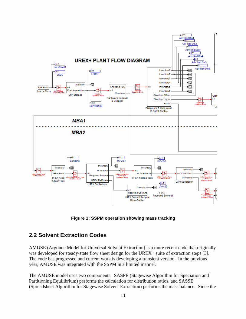
procedures, and physical security data for complete plant monitoring. Figure 1 shows a portion of the model. Black blocks represent key unit functions, blue blocks are measurement points, and red blocks are potential areas for setting up diversion scenarios. Various versions of the model have been created. The baseline model is a UREX+ version that includes the UREX, TRUEX, and TALSPEAK extraction steps. An alternative PUREX model also exists. The UREX+ version is the most up-to-date and was used for the analyses presented here. The original SSPM model used hard assumptions to drive the separation of materials in the various unit operations. For example, the separations efficiencies were assumed for an entire contactor bank, and the bank was treated as a black box in the model. A higher degree of fidelity was desired to improve the plant model and to allow for more realistic propagation of diversion scenarios. Integration with other codes provides more detailed modeling of the individual unit operations.
11
Figure 1: SSPM operation showing mass tracking
2.2 Solvent Extraction Codes AMUSE (Argonne Model for Universal Solvent Extraction) is a more recent code that originally was developed for steady-state flow sheet design for the UREX+ suite of extraction steps [3]. The code has progressed and current work is developing a transient version. In the previous year, AMUSE was integrated with the SSPM in a limited manner. The AMUSE model uses two components. SASPE (Stagewise Algorithm for Speciation and Partitioning Equilibrium) performs the calculation for distribution ratios, and SASSE (Spreadsheet Algorithm for Stagewise Solvent Extraction) performs the mass balance. Since the
12
SSPM already performs a mass balance for each species, only the SASPE code was needed for integration. Researchers at ANL developed a mex file (which is compatible with MATLAB) for SASPE in a version that is universal for a number of aqueous extraction processes. The extraction type, the important species and their concentrations, and the extractants are specified. Previous work was able to demonstrate this integration, but time dependence was not correctly implemented. 2.3 Dissolver Model The Nitron code is a continuous, rotary dissolver model developed at Oak Ridge National Laboratory (ORNL). A more descriptive explanation of the model is given in reference 4. This model assumes continuous introduction of nitric acid and chopped spent fuel in a screw-type dissolver. The dissolver is divided into 10 chambers and rotates slowly to complete dissolution in a several hours. It provides a more uniform output dissolved fuel solution for the rest of the plant. From a startup condition, the dissolver takes about 8-12 hours to reach a fully developed regime. Input parameters, such a nitric acid molarity and feed flow rates can be changed as needed for a particular plant design. The model calculates the concentration of species in solution in each chamber. The SSPM treats dissolution as a black box that achieves an assumed dissolution fraction. The integration with the Nitron code would provide more realism, especially if changes in plant conditions (input parameters) directly affect dissolution rates. Ultimately this can have an impact on diversion scenario analysis, which is why there is interest in merging these capabilities. 2.4 Parallel Processing The integration of additional codes into the SSPM may lead to longer run times. Matlab and Simulink normally only run on one core at a time, and therefore are not taking advantage of multiple cores in current desktop computers. Matlab and Simulink have a Parallel Processing Toolbox that allows for codes and models to be run on clusters or supercomputers. For these models, even just a small cluster or workstation with multiple cores would make a significant improvement in run time. As a smaller effort, this work also examined the use of parallel processing in running Simulink simulations.
13
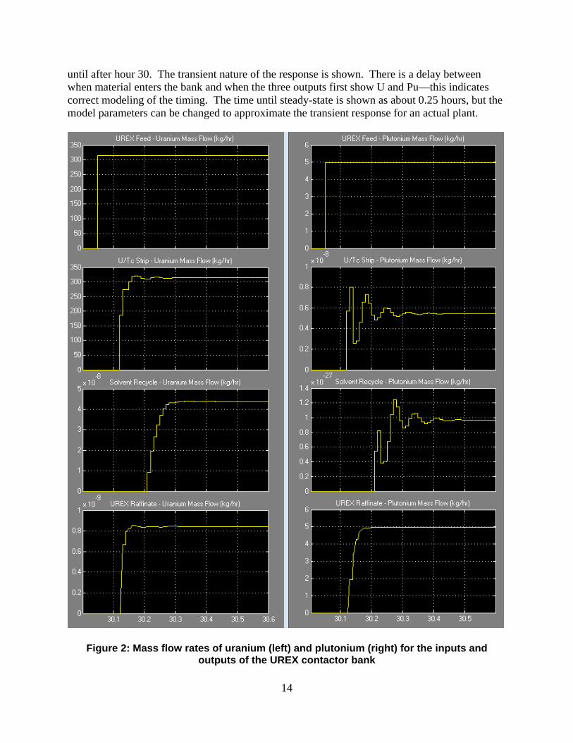
3.0 SASPE Integration The integration of SASPE in the Simulink model required the use of an embedded MATLAB code block that pulls the concentration data from the input streams into a contactor bank. The embedded code sets up the input variables needed for SASPE for that particular contactor bank. The inputs for the SASPE calculation change for the different sections of the contactor bank, so multiple call functions are used. The distribution values are calculated, and then the mass balance across each contactor is used to calculate the output concentrations. The calculation takes into account the counter-flow of the aqueous and organic streams. Reference 7 describes the integration in more detail. The modeling results shown in the previous year’s effort did not correctly deal with the time dependence of the output streams. This was due to a problem in how the mass balance equations were setup. Originally, the mass balances across the contactor banks proceeded in order from contactor 1 to 24. The dissolver solution enters the system at contactor 8, which meant that it would take 8 iterations of the code in order to see nuclear material in the first contactor. However, on the other end, the results from contactor 8 directly fed into the calculation for 9, and so on. Thus, the outputs contained nuclear material immediately, when it should have taken several cycles. The solution to this problem was to perform the mass balance across contactors 1 to 8, and then calculate the mass balance over the rest of the contactors from 24 to 9 in reverse order. After this change was made, the output streams from the contactor bank started at the correct time. The SASPE embedded code must run through multiple times before steady-state is achieved. The user can specify how often the embedded code is run in the model, otherwise it would run on every simulation time step which would significantly slow the model. Time dependence can be approximated by setting the calling time for the SASPE code roughly equal to the filling time of each contactor based on the liquid flow rates. The calling time for the code was set to 0.01 hours, but this calling time was just an approximation and would need to be re-evaluated with actual plant flow streams and contactor sizes. This calling time leads to a noticeable slowdown in the model run time. Once the contactors reach a steady-state condition, the results do not need to be updated so often. In order to fix this issue, the embedded code is setup such that it will only be run if the dissolver solution input to the contactor bank changes above some threshold. There is also a delay time worked in so that the contactors keep updating for 0.6 hours after the slope change occurs. Thus the SASPE calculation occurs at startup and any other transient condition, but does not run during steady-state periods to save computational time. 3.1 Results Figure 2 shows the input and output flow rates into the UREX contactor bank in the SSPM with the updated SASPE integration. The plots on the left show the U mass flow rates, while those on the right shown the Pu mass flow rates. The top graph is the UREX feed, followed by the U/Tc Strip, the solvent output, and finally the UREX raffinate. The x-axis on the bottom is the time in hours during the simulation—at startup the nuclear material does not reach the contactor back
14
until after hour 30. The transient nature of the response is shown. There is a delay between when material enters the bank and when the three outputs first show U and Pu—this indicates correct modeling of the timing. The time until steady-state is shown as about 0.25 hours, but the model parameters can be changed to approximate the transient response for an actual plant.
Figure 2: Mass flow rates of uranium (left) and plutonium (right) for the inputs and outputs of the UREX contactor bank
15
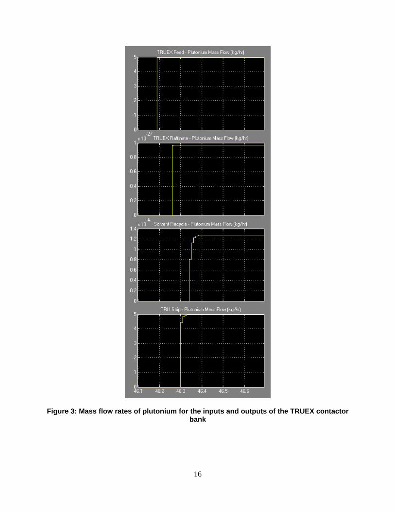
Almost all of the U comes out in the U/Tc strip with only trace amounts going into the raffinate and solvent recycle. Almost all of the Pu comes out in the raffinate with only trace quantities going into the strip and recycled solvent. Figure 3 shows the input and output flow rates into the TRUEX contactor bank in the SSPM with the updated SASPE integration. The plots only show the Pu mass flow rates since the amount of U reaching the TRUEX contactors is very small. The top graph is the TRUEX feed, followed by the TRUEX raffinate, the solvent output, and finally the TRU strip. Material reaches this point in the process near hour 46. The transient response is also evident in this figure, but it appears to reach steady-state quicker than the UREX bank. Again, the actual time dependence can be changed by modifying the model parameters to be representative of actual plant designs. The TALSPEAK contactor bank in the SSPM was not integrated in this fashion since SASPE was not equipped to calculate the distribution values. Future work should examine this integration as the AMUSE work evolves. Additional species should also be examined for integration in the future, especially if they have an effect on the distribution values of the actinides. Currently the UREX integration is only tracking U, Pu, and Tc. The TRUEX integration is tracking Np, Pu, Am, and Cm. Other fission products may have interference effects that could change the results.
16
Figure 3: Mass flow rates of plutonium for the inputs and outputs of the TRUEX contactor
bank
17
4.0 Nitron Integration The Nitron code, developed at ORNL, was developed in an m-file (Matlab source code) version for more easy integration with Simulink. The code was fully developed, and ran in the Matlab workspace without issues. However, integration with the Simulink code led to problems that could not be corrected before the end of the fiscal year. The problems should be resolved in the next fiscal year. The SSPM model in Simulink operates by using signal processing blocks that are part of the library for most of the unit operations. For cases where more complicated functions are required, Simulink contains various user-defined function blocks. These function blocks call a Matlab code that runs embedded in the simulation to perform whatever operations are required. The user writes the code as needed. For integration of other codes, these embedded function blocks are a good way to call external programs. For the Nitron code, the code was written as an m-file for easier integration with Simulink. However, the embedded function blocks do not contain the full suite of Matlab functions available, so calling Nitron in this manner led to a large number of errors that could not be resolved. Fortunately, there are other ways to call m-files in Simulink including Level 2 Matlab S-Functions. Future work will use this route to integrate the Nitron code. The goal of the integration is to keep the original Nitron code the same as much as possible so that any future updates can be easily changed out. The interface between Simulink and Nitron simply passes the input and output variables and calls the code. Very little progress was made on the interface since the embedded function block did not work. Future work will develop this interface in more detail.
18
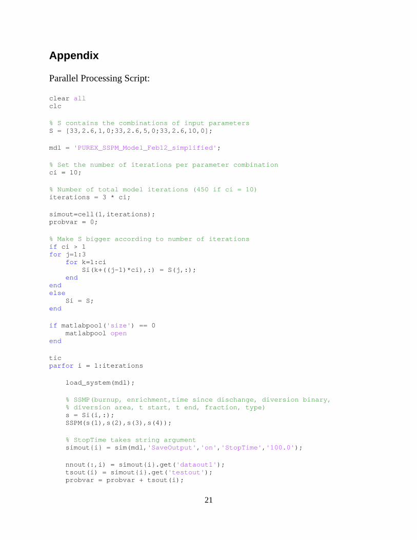
5.0 Parallel Processing As described earlier, the integration of multiple codes into the SSPM can lead to longer run times. As an example, a 1000 hour run may take on the order of 1 hour actual time to complete with multiple codes embedded. The analyses required for safeguards work often require 100 runs to get good enough statistics for detection probabilities, which would take about a week of run time if the simulations are all run in series. By default, Simulink only uses one core on a multi-core processor, so parallel processing is a way to speed up simulations on current desktop computers or small clusters. The Parallel Processing Toolbox provides this capability for Matlab or Simulink. For this work, a Matlab script was setup to run the SSPM in parallel for situations that require multiple runs. The script is shown in the Appendix. This script allows the user to choose multiple input parameters for the SSPM, and multiple iterations at each set of input parameters. The Parallel Processing Toolbox uses the parallel for loop or ‘parfor’ function to run the model on multiple cores. The script can be set up to record the necessary output data from each run as needed. The script was tested as compared to running multiple iterations in series, and on a quad-core computer, the parallel processing worked through the iterations twice as fast. Based on this scaling, a workstation with dual six-core processors should perform the iterations in 1/6 time, which would make a significant improvement. However, the scaling is still somewhat unclear since this has not been tested on larger machines. Regardless, this is a useful capability to have for the future. Additionally, Sandia’s High Performance Computing department has recently deployed a cluster computing capability that runs a Matlab Distributed Computing Server license pool with 224 cores (with plans to expand to 1152 cores.) If it is deemed necessary to run large parameter sweep simulations with the SSPM code this capability can be utilized at a relatively low cost.
19
6.0 Conclusion The SASPE integration with the SSPM provides solvent extraction chemistry modeling, which was a weakness of the original model. The integration with the UREX and TRUEX contactor banks demonstrated transient modeling and provides a more realistic plant model for safeguards analysis. Future work can increase the number of species tracked and evaluate integration of TALSPEAK. The Nitron integration with the SSPM still requires much more work to get the integration working. Although the Nitron code works well as a stand-alone model, time constraints prevented much progress in the integration. Future efforts will also examine the interface that passes variables back and forth. The parallel processing capability for the SSPM is a significant improvement over running multiple iterations of the model in series. The capability was setup to allow for multiple input conditions, which will provide more rapid analyses in the future. This capability will also make up for slowdowns due to integrating multiple codes.
20
7.0 References 1. B.B. Cipiti, “Separations and Safeguards Performance Modeling for Advanced
Reprocessing Facility Design,” Journal of Nuclear Materials Management, 39/2 pp. 4-14 (January 2011).
2. R.H. Rainey and S.B. Watson, “Modification of the SEPHIS Computer Code for Calculating the PUREX Solvent Extraction System,” ORNL-TM-5123, Oak Ridge National Laboratory (1975).
3. M.C. Regalbuto et al., "Solvent Extraction Process Development for Partitioning and Transmutation of Spent Fuel," Actinide and Fission Product Partitioning and Transmutation, Eighth Information Exchange Meeting, Nuclear Energy Agency Organization for Economic Co-operation and Development, Las Vegas, Nevada (2004).
4. V.F. de Almeida, “Plant-Level Modeling and Simulation of Used Nuclear Fuel Dissolution,” ORNL/TM-2012/375 (September 2012).
Appendix Parallel Processing Script: clear all clc % S contains the combinations of input parameters S = [33,2.6,1,0;33,2.6,5,0;33,2.6,10,0]; mdl = 'PUREX_SSPM_Model_Feb12_simplified'; % Set the number of iterations per parameter combination ci = 10; % Number of total model iterations (450 if ci = 10) iterations = 3 * ci; simout=cell(1,iterations); probvar = 0; % Make S bigger according to number of iterations if ci > 1 for j=1:3 for k=1:ci Si(k+((j-1)*ci),:) = S(j,:); end end else Si = S; end if matlabpool('size') == 0 matlabpool open end tic parfor i = 1:iterations load_system(mdl); % SSMP(burnup, enrichment,time since dischange, diversion binary, % diversion area, t start, t end, fraction, type) s = Si(i,:); SSPM(s(1),s(2),s(3),s(4)); % StopTime takes string argument simout{i} = sim(mdl,'SaveOutput','on','StopTime','100.0'); nnout(:,i) = simout{i}.get('dataout1'); tsout(i) = simout{i}.get('testout'); probvar = probvar + tsout(i);
22
end toc str = ['Cumulative results of probvar = ', num2str(probvar)]; disp(str); matlabpool close;
23
Distribution 1 Terry Todd
Idaho National Laboratory 2525 Fremont Ave. Idaho Falls, ID 83415
1 James Bresee U.S. Department of Energy 1000 Independence Ave. SW Washington, DC 20585
1 Jack Law Idaho National Laboratory 2525 Fremont Ave. Idaho Falls, ID 83415
1 Valmor de Almeida
Oak Ridge National Laboratory PO Box 2008 Oak Ridge, TN 37831
1 MS 0747 Ben Cipiti, 6223 1 MS 1374 Mike McDaniel, 6832 1 MS 0474 Ken Sorenson, 6223 1 MS 0899 Technical Library, 9536 (electronic copy)