REPUBLIC OF KENYA MINISTRY OF TRANSPORT, INFRASTRUCTURE, HOUSING AND URBAN DEVELOPMENT STATE DEPARTMENT OF TRANSPORT Telegrams: “TRANSCOMS”. Nairobi TRANSCOM BUILDING Telephone: (020) 2729200 GONG ROAD Email: [email protected]P.O. Box 52692 - 00100 Website: www.transport.go.ke NAIROBI AIR ACCIDENT INVESTIGATION PRELIMINAR ACCIDENT REPORT 5Y-NPS 08.09.2016 OBJECTIVE This report contains factual information which has been determined up to the time of publication. The information in this report is published to inform the aviation industry and the public of the general circumstances of accidents, serious incidents and inci- dents. This investigation has been carried out in accordance with The Kenya Civil Aviation (Air- craft Accident and Incident Investigation) Regulations, 2013 and Annex 13 to the ICAO Convention on International Civil Aviation. The objective of the investigation of an accident or incident under these Regulations shall be the prevention of accidents and incidents. It shall not be the purpose of such an investigation to apportion blame or liability.
1.1 History of the Flight................................................................................................................................................ 6
1.2 Injuries to Persons............................................................................................................................ 7
1.3 Damage to Aircraft ........................................................................................................................... 7
1.4 Other Damage ............................................................................................................................. ..... 7
1.5 Personnel Information ...................................................................................................................... 8
1.6 Aircraft Information ........................................................................................................................... 9
1.6.1 Maintenance Information ............................................................................................................. 10
1.7 Meteorological Information ............................................................................................................... 10
1.8 Aids to Navigation ............................................................................................................................ 11
1.12 Wreckage and Impact Information ................................................................................................... 12
1.13 Medical and Pathological Information .............................................................................................. 12
1.14 Fire ................................................................................................................................................... 12
3.1 Main findings .................................................................................................................................. 33
3.2 Accident probable cause ................................................................................................................ 33
3.3 Protective and Corrective Measures …………….............................................................................33
4
ABBREVIATIONS
AAID - Air Accident Investigation Department
AMSL - Above Mean Sea Level
ATC - Air Traffic Control
ATPL - Airline Transport Pilot’s License
CPL - Commercial Pilot Licence
FL - Flight Level
FLIR - Forward-Looking Infra-Red
FO - First Officer
ICAO - International Civil Aviation Organization
ICS - internal communication system
IR - Instrument Rating
ITT - Inter-Turbine Temperature
JKIA - Jomo Kenyatta International Airport
KCAA - Kenya Civil Aviation Authority
MLG - Main Landing Gear
MPFR - Multi-Purpose Flight Recorder
PPL - Private Pilot Licence
SOP’s - Standard Operating Procedures
VHF - very high frequency
5
SYNOPSIS
On 08 September 2016, at approximately 1505 hours, the Air Accident Investigation
Department (AAID) was notified of an accident by the Wilson Airport (HKNW) Air Traffic
Control (ATC). Investigators reported on site on 09 September 2016.
At 1303 hours on 08 September 2016, Agusta helicopter AW 139 registration 5Y-NPS
crash-landed in Mathare, Nairobi while on a routine surveillance mission with four oc-
cupants. The four occupants were extricated from the wreckage with serious injuries
as a result of the occurrence and were taken to hospital. The aircraft was damaged af-
ter colliding with the ground surface.
At the time of publication of this preliminary report, the probable cause of the accident
had not been established. The downloaded data from a Curtiss Wright Multi-Purpose
Flight Recorder (MPFR) by the manufacturer did not indicate any malfunction of the
aircraft and its major components at the time of the accident. However, the key con-
tributory factor to the possible cause of the accident inter alia was lack of appropriate
experience by the flight crew on the type of aircraft being flown.
6
1. Factual information
1.1 History of Flight
At 13:03:26, an Agusta Westland AW139 helicopter, registered 5Y-NPS,
departed from Wilson airport, Nairobi to perform both reconnaissance mission
and equipment training with 4 crewmembers on board: 2 Pilots, one Flight
Engineer and one maintenance Technician. No visibility restriction or other
significant meteorological conditions prevailed at the time of flight.
After a brief flight of approximately 9 minutes, the helicopter established hover
above the Mathare area in Nairobi, at approximately 5700ft barometric altitude.
Witnesses from the ground reported that the aircraft spent about 2 minutes in
HOGE above Mathare, before suddenly losing altitude and crashing inside the
perimeter of the National Youth Service Engineering Institute, while spinning
around the vertical axis with a significant yaw rate at 13.15 UTC, consistent with
videos posted on social Medias.
The final resting position of the Aircraft wreckage was 1.255647°S 36.864251°E.
All the four crewmembers were extricated from the wreckage and hospitalized with
varying degrees of injuries.
Figure 1 – Take-Off and Crash site in Mathare, Nairobi
7
1.2 Injuries to Persons
Injuries
Crew
Passengers
Others
Fatal
0
0
0
Serious
3
0
0
Minor
1
0
None
0
0
1.3 Damage to Aircraft
The helicopter was damaged by impact forces: the Nose and Cockpit sections showed
significant structural damages, while the Tail unit was detached from the rest of the
empennage and lay in the nearby field with the rest of the wreckage. All components were
recovered and accounted for.
Figure 2 – The tail section detached from the main body
1.4 Other Damage
Both the surrounding trees and part of the ground suffered lesions after contacting the propellers
8
Figure 3 – The trees at the accident site
1.5 Personnel Information
Captain
The pilot is a holder of both Private and Commercial Pilot (Helicopter) License issued on 22nd May,
2013 and 4th August, 2015 respectively. The AW139 was endorsed on his PPL and not CPL without a
Command (Multi-engine Helicopter) Instrument Rating. The pilot also held a Class 1 Aviation Medical
Certificate with restriction to wear corrective lens for far vision correction.
The pilot’s logbook indicated that, prior to the accident flight; he had accrued a total of 671.8
helicopter flight time, of which 2.3 hours were command hours on AW139 helicopters.
Pilot
The pilot is a holder of both Private and Commercial Pilot (Helicopter) License issued on 08/01/2014
and 08/01/2014 respectively. The AW139 was endorsed on his PPL and not CPL without a Command
(Multi-engine Helicopter) Instrument Rating. The pilot also held a Class 1 Aviation Medical Certificate
with no restrictions.
The pilot’s logbook indicated that, prior to the accident flight; he had accrued a total of 655 helicopter
flight time, without command hours on AW139 helicopters.
No evidence was found to show that either pilot had received training for their initial instrument
ratings. The type rating was conducted entirely under visual flight rules
9
1.6 Aircraft Information
Aircraft specifications
The AW139 is a medium -sized, single main and tail rotor helicopter that is powered by two turbine
engines and equipped with retractable landing gear. 5Y-NPS was equipped with special equipment for
reconnaissance missions.
Forward-Looking Infra-Red (FLIR)
The helicopter was fitted with a Forward-Looking Infra-Red (FLIR) system; live imagery from an IR
camera mounted beneath the helicopter’s nose could be selected on one of the displays in the cockpit.
The status of the system was not recorded and the CVFDR contained no reference to the system by the
pilots.
Figure 4 – 5Y-NPS with surveillance camera
Radio communication system
The helicopter was equipped with four radios (designated COM 1 to 4) and an onboard telephone. COM
1 and COM 2 were very high frequency (VHF) radios used by the pilot for communication with air
traffic. The air crew (ACM) could talk on the helicopter’s internal communication system (ICS) or
transmit externally via the installed radios.
10
Figure 5: ICS control panel
1.6.1 Maintenance information
Maintenance history
A review of the helicopter’s maintenance documentation identified that; at the time of the accident, the
helicopter had not been issued with a Certificate of Airworthiness.
Detailed examination
Inspection of the rotor drive train confirmed that there was no evidence of a failure with either engine or
any of the elements of the main and tail rotor drive trains. Reconstruction of the flying control circuits
and examination of the main and tail rotor hydraulic actuators confirmed that all the damage was
consistent with the impact forces and that there was no evidence of a pre impact defect or restriction
within any of the flying controls.
1.7 Meteorological information
The reported weather was CAVOK. The weather conditions at the location of the accident at the time
of the accident were of Light winds, with no precipitation, significant low cloud or other visibility
reducing phenomena present.
11
1.8 Aids to Navigation
N/A
1.9 Communications
N/A
1.10 Aerodrome Information
N/A
1.11 Flight Recorders
The Aircraft was equipped with a Curtiss Wright Multi-Purpose Flight Recorder (MPFR)
Model D51615-142, which is able to record 25 flight hours of continuous data, plus 2
hours of audio on 4 different channels (pilot head- set, Co-Pilot headset, Intercom and
Cockpit Area Microphone).
Additionally other Non-Volatile Memories are contained within the Central Maintenance
Computer (CMC), the two Engine Data Collection units (DCUs), the Health and Usage
Monitoring System (HUMS) PCMCIA card and the Compact Flash Card of the FLIR video
camera.
12
1.12 Wreckage and Impact Information
Figure 6–wreckage layout
1.13 Medical and Pathological Information
N/A
1.14 Fire
There was neither pre nor post impact fire.
1.15 Survival Aspects
N/A
1.16 Test and Research
N/A
1.17 Organizational and Management Information
The operator
The Police Air wing operates other types of helicopters without an Air Operator’s Certificate
13
Previous accident
The last accident involving Police air wing was a Bell 206L4 type of helicopter which occurred on
22/08/2016.
1.18 Additional Information
N/A
14
2. Analysis
2.1 MPFR Data Recovery and Analysis
The data and audio were successfully recovered from the MPFR using the dedicated recovery kit
provided by the equipment Manufacturer (Curtiss Wright): as the external casing of the MPFR
was damaged during the crash, an additional spare unit was used to interface with the protected
memory and download the FDR and CVR data.
Figure 7 – MPFR data and audio Recovery
The following is the outcome of the preliminary MPFR data analysis performed on site:
1. The Flight of 5Y-NPS was uneventful up to 13:14:49 UTC when the chain of events started
2. No presence of Warnings or Cautions is recorded during Flight prior to this point, thus
excluding any associated aircraft system malfunction
3. The aircraft was performing HOGE at approximately 5770ft AMSL and 25°C OAT, which
is within the performances capabilities of AW139 in the configuration of 5Y-NPS (with Inlet
Barrier Filters installed on the Engines’ intakes and ECS ON)
4. Before the event the aircraft was being flown hands-on (detent switch is active on the Cyclic Stick
And FTR is active on Pedals) with Flight Director Altitude Hold (ALT) mode activated on the vertical axis
15
5. Engine Torque Limiter was selected ON soon after take-off, thus limiting the available
aircraft power to AEO TOP (110% Torque). The Engines’ response is considered consistent
with Collective control inputs throughout the whole Flight
6. The initial chain of events started with an intentional controls’ input identified by the activation
of FTR Switches on Collective and Cyclic Sticks at approximately 13:14:49 UTC
7. A significant Collective control input increase resulted in the Engines’ torque limiting and
the Consequent NR droop to 96% (13:14:52), triggering the ROTOR LOW Aural Warning below 98% (13:14:51)
8. At the same time the Pilot was also trying to compensate the increased Right hand yawing
moment of the aircraft with an increase of Pedal control towards Left Hand, but the
decreased NR coupled with the demanding conditions caused a reduction in the Tail Rotor anti-torque effect and therefore the
Pedal reached the saturation (100% to the LH at 13:14:51) without fully arresting the A/C RH rotation
9. The Collective was subsequently lowered down to 20% in about 2.5s (13:14:55), causing
NR to re- turn at 100% but also reducing the Collective Pitch of the Main Rotor Blades and therefore leading the A/C into a steep
descent, while the A/C was also yawing to the Left (as a result of the decreased Tq)
10. At the same time of point 9 large inputs were also applied to the Cyclic Stick (both
longitudinally and laterally), possibly in an attempt to control the A/C attitudes during the
descent: the aircraft reached 20° nose-down and started to accelerate to about 60kts ground
speed, with increasing vertical speed (in excess of 4000 feett/min, estimated from pressure
and radar altitude variations)
11. Aircraft behavior in relation to the attitudes is considered consistent with these control
inputs until the final phase of the Flight
12. This very high rate of descent combined with a very low ground speed could have resulted
in a
Vortex Ring State phenomenon, further reducing the aircraft controllability in the final phase
of the descent
16
13. A sudden rise in the Collective input at 220ft AGL and 60kts, without any Pedal
compensation by the Pilot, resulted in a dramatic increase in the yaw rate of the aircraft,
which greatly exceeded 128°/s (saturation of the correspondent sensor) at approx. 13:15:03
14. After this point in time the aircraft entered in a spiraling motion toward the terrain, and
crashed approximately 3 to 4 seconds later. Data and voice recording was lost, possibly due
to MPFR disconnection from the avionic bus caused by the impact on the Nose. The Cockpit
Area Microphone remained active during the subsequent rescue phases, due to the presence
of the Remote Independent Power Supply (RIPS) of the MPFR
Time histories of the relevant aircraft parameters for the final portion of the Accident Flight are
reported in the following pages
17
Figure 8 – Time Histories of the main Engines’ parameters prior and during the event
18
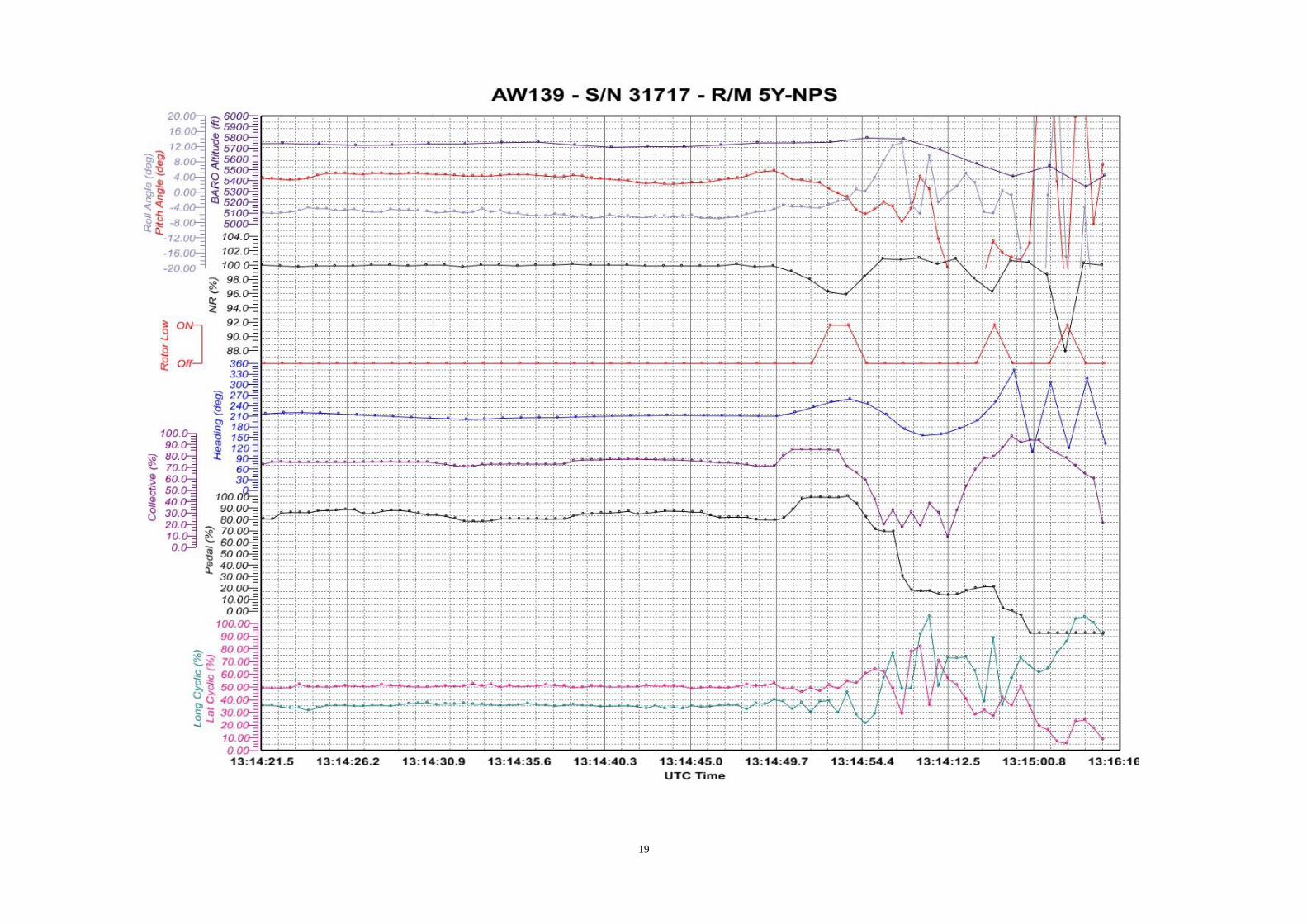
Figure 5 – Time Histories of Figure 9 – Time Histories of the main Flight Controls’ parameters prior and during the event
19
20
Figure 10 – Time Histories of the Aircraft attitudes and Controls parameters prior and during the even
Figure 11 – Time Histories of the Aircraft attitudes and Controls parameters prior and during the even
21
INTENTIONALLY LEFT BLANK
22
2.2 CVR Transcript
The following is a preliminary CVR transcript, related to the final 6 minutes of Flight.
Synchronization has been achieved using the ROTOR LOW Aural Warning time reference within
the FDR data.
UTC Time
CVR Time
Text
1:54:12 you can come to the right, there is a “Baraboo stock” yet down there, yeah, I think you can come to the right;
1:55:43 you are manually hovering, yeah he is manually hovering w/o hover, you know how to hover, yeah he do know how to hover, yeah
1:55:58 You are moving to the right
1:56:01 You are hovering to the right. Yeah I think I got it (?)
1:56:26 Down left, Down, left, shaft left, shaft left
1:56:40 I go there, I try to hover
1:56:46 Power almost to the yellow. Yeah, it’s what you need to hover
1:56:57 don’t go to there, it’s the dump site, there is a dump site
1:57:00 I see, just down left
1:57:04 The camera is ok?
1:57:05 The camera is ok, ok
1:57:40 There is a (?)in front of me, “Baraboo stock”
1:57:53 maybe you can go down a bit
1:58:27 (?) You (?) for me the altitude? ALT is coming ON, OK
1:59:14 Oh you have a left cross, Yeah I have a left cross
1:59:15 really pushing
1:59:20 you see that, what they are talking about (?) …the (?) coming to the airline
It is big, he can do better than you had, you can trust me
1:59:30 yeah heavy, that’s why
2:00:44 ok, maybe you can burn a little of fuel
2:00:48 Ue, Ue, Ue, Ua, Ua..
2:00:50 Yeah, they are coming in
2:00:51 Oh, on the right, [unintelligible]
13:14:51 2:00:52 Martin
“ROTOR LOW”, “ROTOR LOW”
2:00:57 Oh, what happen, let’s go, let’s go, no, no, no, Oduk
2:00:58 Oduk, let’s go
2:00:59 Oduk, Oduk, Oduk, Let’s go, no, no , no, Martin, no
2:01:03 “MWL BEEP”
2:01:05 “ROTOR LOW”, “ROTOR LOW”
13:15:05 2:01:06 IMPACT NOISE
2.3 Wreckage Survey
The wreckage was inspected on the crash site on the 09th
September 2016.
23
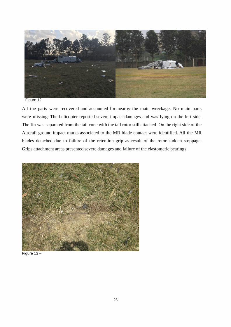
Figure 12
All the parts were recovered and accounted for nearby the main wreckage. No main parts
were missing. The helicopter reported severe impact damages and was lying on the left side.
The fin was separated from the tail cone with the tail rotor still attached. On the right side of the
Aircraft ground impact marks associated to the MR blade contact were identified. All the MR
blades detached due to failure of the retention grip as result of the rotor sudden stoppage.
Grips attachment areas presented severe damages and failure of the elastomeric bearings.
Figure 13 –
24
Figure 14 –
The Rotor stoppage induced also failure of the MR dampers. The failures were assessed as
static overload and therefore consistent with consequential impact damages.
Figure 15
Rotating and fixed swashplates were still in position with both the rotating scissors connected. Four
MR pitch link were broken at the lower rod end meanwhile the fifth one was still connected. All
25
the pitch link failures have been assessed as static overload and therefore accident consequential
damages.
Figure 16
The three MR servo actuators were still connected to the Main Gearbox and the input rod
connected to the servo input lever. The Main Gearbox was still connected to the mountings rods as
well as the related at- tachment to the MGB and upper deck, with no notable damages.
The anti-torque beam was still connected to the MGB and to the roof
structure.
26
Figure17
Considering the good connection of the MGB to the main frame, it was suggested to lift up the
wreckage from the main rotor head with a crane. When the A/C is lifted fuel can be easily drained
from the bottom draining valves.
Engines to transmission drive shafts were still connected meanwhile the engine #1 gimbal flange
was detached due to failure of the connection bolts.
Figure 18 –
The tail boom was partially detached from the rear fuselage; the two upper connecting bolts failed
and fracture present static overload characteristics.
27
Figure 19
The tail rotor drive shaft #1 at the connection to the hanger bearing presents rotational marks due to
contact with the fairing.
Figure 20
The hanger bearing itself was detached from the fuselage due to failure of the honeycomb
sandwich panel. The tail rotor drive line cover was checked and found without any evidence of
contact damages with the hanger bearing and therefore excluding in flight detachment. The bearing
was positively verified for freedom of rotation.
28
Figure 21
The drive shaft #2 was broken into three parts; the fractures were due to static overload and plastic
deformation providing evidence of the applied torque. This damage is possibly associated with TR
sudden stop- page as result of the impact.
Figure 22
The drive shaft #3 was still connected to the Intermediate Gear Box and presented the fracture of
the sheet coupling to the Tail Rotor Gearbox. Drive continuity within the IGB have been positively
verified.
29
Figure23
The tail rotor fixed control chain could be verified for the visible portion from the rod yaw #7 up to the
yaw#10, which is connected to the TR input lever. All the fractures have been assessed as static overload.
Figure 24
TR servo control input lever was detached and the fractures have been assessed as static overload.
30
Figure25
The Tail Rotor Gearbox was still connected to the attachment on the fin and with no notable
damages on the case; the chip detector connector was partially detached with an evident oil leakage.
Figure 26
The Tail Rotor was still connected to the mast; three TR blades were failed in bending at root
section mean- while the other was connected with damage in the root section. Bending fractures are
consistent with Consequential damages caused by tail fin detachment.
31
Figure 27
Rotating controls were connected with no failures; just one of the pitch link out of 4 was slightly
bent and the two rotating scissor were also connected.
Figure 28
32
The TR dampers were connected and presented central body damages consistent with TR sudden
stop- page.
Figure 29
All the verified fractures did not show progressive failure mode (e.g. due to fatigue), while
presenting instead the typical morphology of static overload and are therefore consistent with
impact consequential damages. No evidence of pre-existing failure could be identified within the
wreckage.
33
3. Considerations
3.1 Main findings
The preliminary investigation highlighted the following points:
1. FDR data analysis does not highlight evidence of any aircraft related malfunction
2. Wreckage survey did not identify any component affected by progressive
failure mode (e.g. due to fatigue), while presenting instead the typical
morphology of static overload on all the components. This is consistent with
impact consequential damages.
3. There was no evidence of pre-existing failure that was identified at the wreckage.
4. The two pilots did not have flight command experience on AW139 type of helicopter