60
REQUEST FOR PROPOSAL UNINTERRUPTIBLE POWER SUPPLIES SYSTEMS MOHAWK GAMING ENTERPRISES, LLC 873 STATE RTE 37 AKWESASNE, NY 13655 REFERENCE# RFP2014-6

REQUEST FOR PROPOSAL
UNINTERRUPTIBLE POWER SUPPLIES SYSTEMS
MOHAWK GAMING ENTERPRISES, LLC
873 STATE RTE 37
AKWESASNE, NY 13655
REFERENCE# RFP2014-6
Page 1
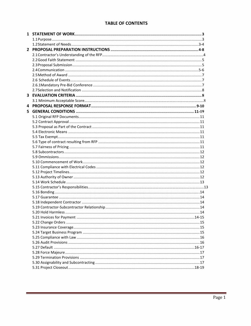
TABLE OF CONTENTS
1 STATEMENT OF WORK ..................................................................................................................... 3 1.1 Purpose ................................................................................................................................................. 3 1.2 Statement of Needs ........................................................................................................................... 3-4
2 PROPOSAL PREPARATION INSTRUCTIONS ................................................................................. 4-8 2.1 Contractor’s Understanding of the RFP……………………………………………………………………………………………..4 2.2 Good Faith Statement .......................................................................................................................... 5 2.3 Proposal Submission ............................................................................................................................. 5 2.4 Communication ................................................................................................................................. 5-6 2.5 Method of Award ................................................................................................................................. 7 2.6 Schedule of Events ............................................................................................................................... 7 2.6.1Mandatory Pre-Bid Conference ......................................................................................................... 7 2.7 Selection and Notification .................................................................................................................... 8
3 EVALUATION CRITERIA .................................................................................................................... 8 3.1 Minimum Acceptable Score……………………………………………………………………………………..……………………….8 4 PROPOSAL RESPONSE FORMAT ................................................................................................. 9-10 5 GENERAL CONDITIONS ............................................................................................................. 11-19
5.1 Original RFP Documents..................................................................................................................... 11 5.2 Contract Approval .............................................................................................................................. 11 5.3 Proposal as Part of the Contract ........................................................................................................ 11 5.4 Electronic Means ............................................................................................................................... 11 5.5 Tax Exempt ......................................................................................................................................... 11 5.6 Type of contract resulting from RFP .................................................................................................. 11 5.7 Fairness of Pricing .............................................................................................................................. 11 5.8 Subcontractors ................................................................................................................................... 12 5.9 Ommissions ........................................................................................................................................ 12 5.10 Commencement of Work ................................................................................................................. 12 5.11 Compliance with Electrical Codes .................................................................................................... 12 5.12 Project Timelines .............................................................................................................................. 12 5.13 Authority of Owner .......................................................................................................................... 12 5.14 Work Schedule ................................................................................................................................. 13 5.15 Contractor’s Responsibilities.....………………………………………………………………………………………………….…..13 5.16 Bonding ........................................................................................................................................... .14 5.17 Guarantee ........................................................................................................................................ 14 5.18 Independent Contractor .................................................................................................................. 14 5.19 Contractor-Subcontractor Relationship ........................................................................................... 14 5.20 Hold Harmless .................................................................................................................................. 14 5.21 Invoices for Payment .................................................................................................................. 14-15 5.22 Change Orders ................................................................................................................................. 15 5.23 Insurance Coverage .......................................................................................................................... 15 5.24 Target Business Program ................................................................................................................. 15 5.25 Compliance with Law ....................................................................................................................... 16 5.26 Audit Provisions ............................................................................................................................... 16 5.27 Default ........................................................................................................................................ 16-17 5.28 Force Majeure .................................................................................................................................. 17 5.29 Termination Provisions .................................................................................................................... 17 5.30 Assignability and Subcontracting ..................................................................................................... 17 5.31 Project Closeout .......................................................................................................................... 18-19
Page 2
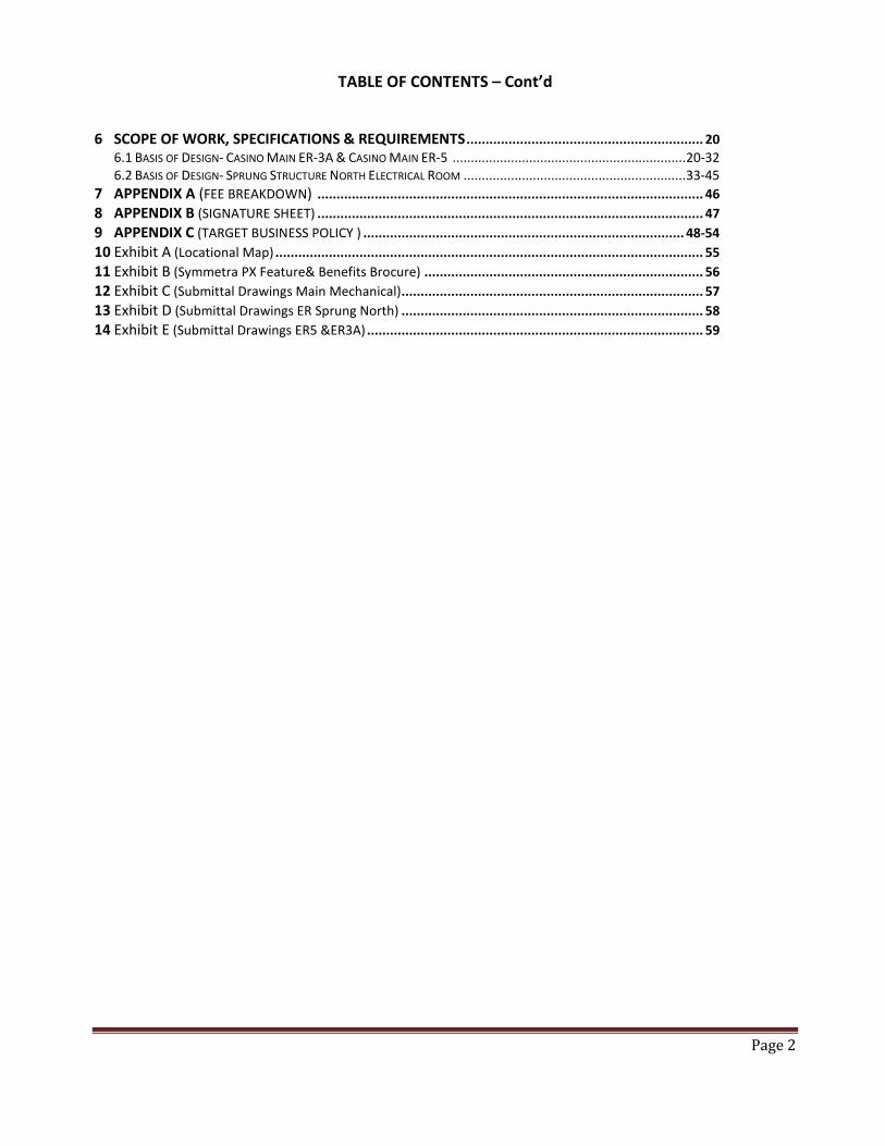
TABLE OF CONTENTS – Cont’d
6 SCOPE OF WORK, SPECIFICATIONS & REQUIREMENTS .............................................................. 20
6.1 BASIS OF DESIGN- CASINO MAIN ER-3A & CASINO MAIN ER-5 ................................................................ 20-32 6.2 BASIS OF DESIGN- SPRUNG STRUCTURE NORTH ELECTRICAL ROOM ............................................................. 33-45
7 APPENDIX A (FEE BREAKDOWN) ..................................................................................................... 46 8 APPENDIX B (SIGNATURE SHEET) ..................................................................................................... 47 9 APPENDIX C (TARGET BUSINESS POLICY ) .................................................................................... 48-54 10 Exhibit A (Locational Map) ................................................................................................................ 55 11 Exhibit B (Symmetra PX Feature& Benefits Brocure) ......................................................................... 56 12 Exhibit C (Submittal Drawings Main Mechanical) ............................................................................... 57 13 Exhibit D (Submittal Drawings ER Sprung North) ............................................................................... 58 14 Exhibit E (Submittal Drawings ER5 &ER3A) ........................................................................................ 59

Page 3
1 Statement of Work
1.1 Purpose
The purpose of this Request for Proposal (RFP) is to invite proposals from Contractors capable of providing “turn-key” services for the installation of two (2) 225 kVA, and one (1) 125kVA power system (UPS) as specified herein.
1.2 Statement of Needs
The Contractor to whom a contract is awarded under this RFP will assume complete responsibility for engineering, design, equipment, and installing the UPS systems such that the functional needs as described in this RFP are fully met and operational on a turn-key basis. Proposals shall include all costs of contracts, agreements, insurance, licensing fees, materials, labor, and any other costs necessary to complete this project.
Contractor shall propose a complete Uninterruptible Power System package. If the Successful Contractor’s package as installed does not meet the technical requirements of this RFP and any resulting contract, all additions or modifications required to meet those technical requirements to the satisfaction of the Mohawk Gaming Enterprise herein referred as (Owner) shall be at the sole expense of the Successful Contractor.
The major component of the Package is for the Contractor to provide and install three (3) Uninterruptible Power Systems (UPS) rated for a minimum of 5 minutes of run time and shall provide systems with sufficient capacity to allow 10% growth. One located at the Casino Main Electrical Room- 3A&3B, Casino Main Electrical Room- ER5, and the other at Casino Sprung Structure- North Electrical Room. All UPS equipment shall be new and factory tested. Said UPS units shall be compatible with and be synchronized with the Owner’s emergency back -up generators. Contractor must complete a successful full load field test as well as testing of the UPS systems compatibility with the Owner’s emergency back-up generator will be required of the UPS unit supplied by this procurement.
This RFP and any resulting agreement contemplates and requires the “turnkey”, installation, testing, and delivery of two (2) 225 kVA and one (1) one 125 kVA Uninterruptible Power System(s) components as specified by this RFP and any resulting agreement. The Successful Contractor shall furnish without limitation, all materials, equipment, tools, skill, engineering, and labor necessary to fully complete in a timely and workmanlike manner the requirements of this RFP and any resulting agreement according to the specifications, terms, and conditions contained in this RFP and any resulting agreement.

Page 4
The Owner has completed, or is in the process of completing, certain tasks related to system implementation. Work by the Owner includes:
1. Construction of room UPS units are to be housed and installation of HVAC system for temperature control.
2. Due to time constraints of the Project the Owner will be purchasing the UPS units direct from the manufacturer. The Owner has a standing order with APC based on the manufacturer’s site visit and is awaiting Owner’s signature of approval on the submittals prior to manufacturing the units for this project. The submittals have been included in bid for Contractor’s review. The package includes assembly and start-up services so please make sure you are not factoring this in your bid price.
Existing conditions: Refer to Exhibit A – Map of zones impacted and where Electrical Rooms are located and possible locations for back UPS systems.
Back-Up Generator: Caterpillar 1750kW, Model # SR4, Serial#5WN00668, Engine Model-3516, Engine Serial #25Z05147.
Back-Up to Back-Up Generator: Caterpillar, Model # SR4B, Serial#5WN00667, Engine Model-3516, Engine Serial#25Z05148.
Electrical Room(s) ER-3A&3B – Area impacted #2 – Existing 300kVA transformer is fed from a 400amp disconnect mounted on the feeder bus duct. The UPS unit will be located in a revised room/space approximately 30 feet from ER-3A.
Electrical Room ER-5 – Area impacted #3 – Existing 300kVA transformer is fed from a 400amp disconnect mounted on the feeder bus duct. Two possible scenarios for UPS location (a) Run electrical from ER5 location overhead to main ups room C-526 that currently houses UPS units for area #1. Or (b) Owner to construct a room located near East Entrance that is currently serving as office space to the Director of Casino Services. Contractor to recommend the most cost efficient option that will require the least amount of down time to the area impacted.
Sprung Structure North Electrical Room – Area impacted # 4 – Existing 150kVA transformer. The UPS unit will be housed in the former lift storage room.
3. Basis of Design: A basis of design is provided in this RFP under Section 6 Scope of Work, Specifications & Requirements.
2 Proposal Preparation Instructions
2.1 In responding to this RFP, the Contractor accepts the responsibility fully to understand the RFP in its entirety, and in detail, including making any inquiries to Owner as necessary to gain such understanding. Owner reserves the right to disqualify any Contractor who demonstrates less than such understanding. Further, Owner reserves the right to determine, at its sole discretion, whether the Contractor has demonstrated such understanding. That right extends to cancellation of award if award has been made. Such disqualification and/or cancellation shall be at no fault, cost, or liability whatsoever to Owner.
Proponents are solely responsible for their own expenses in preparing, presenting or delivering a proposal.

Page 5
2.2 Good Faith Statement
While Owner has made considerable efforts to ensure an accurate representation of information in this RFP, the information contained in this RFP is supplied solely as a guideline for proponents. The information is not guaranteed or warranted to be absolutely accurate by the Owner, nor is it necessarily comprehensive or exhaustive. Nothing in this RFP is intended to relieve proponents from forming their own opinions and conclusions with respect to the matters addressed in this RFP. This document or any portion thereof may not be used for any purpose other than the submission of proposals.
Proponent responses must be signed by an authorized officer of the firm.
Information pertaining to this RFP or any material obtained by the proponent as a result of participation in this project is confidential and must not be disclosed without written authorization from Owner.
2.3 Proposal Submission
Proposals must be SEALED, addressed and delivered to the Akwesasne Mohawk Casino purchasing department, prior to the closing of 4:00 p.m. on March 28th, 2014. Please indicate the Reference Number RFP2014-6 on your document and envelope.
Mailing Address: Attn: Brooke Moreau – Purchasing Department Akwesasne Mohawk Casino – ADMIN BLDG PO BOX 1179
921 State Route 37 Akwesasne, NY 13655
Owner shall not accept proposals received by fax or e-mail.
Late proposals received after the closing date and time will be disqualified from competition and returned to the respondent unopened.
Contractors are to submit two (2) original copies of proposal marked “Original” and four (4) copies. Each original and copy must be individually bound.
Contractors must complete and return the Signature Sheet (Appendix B) and Targeted Business Plan with a bid response (See Appendix C).
2.4 Communication
Verbal communication shall not be effective unless formally confirmed in writing by specified procurement official in charge of managing this RFP process. In no case shall verbal communication govern over written communication.
Respondents wishing to amend an already submitted proposal must submit the amendment in writing before the designated closing date/time provided they are properly identified by company name, RFP number and due date.
Page 6
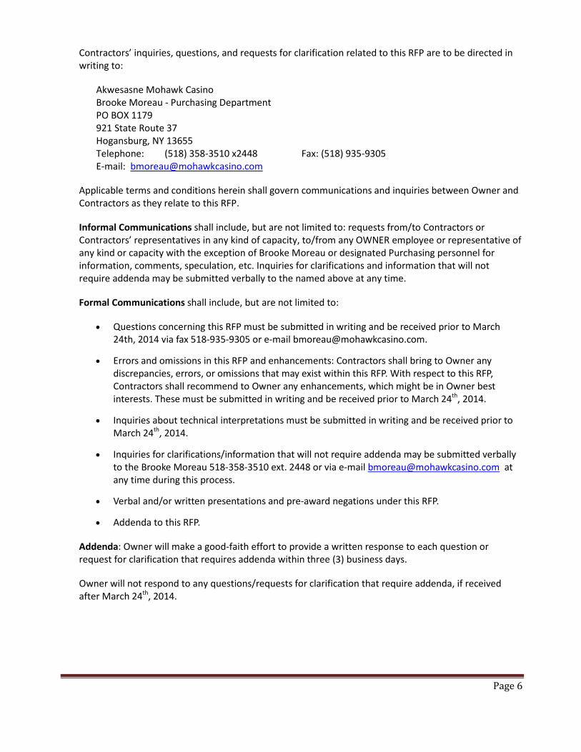
Contractors’ inquiries, questions, and requests for clarification related to this RFP are to be directed in writing to:
Akwesasne Mohawk Casino Brooke Moreau - Purchasing Department PO BOX 1179 921 State Route 37 Hogansburg, NY 13655 Telephone: (518) 358-3510 x2448 Fax: (518) 935-9305 E-mail: [email protected]
Applicable terms and conditions herein shall govern communications and inquiries between Owner and Contractors as they relate to this RFP.
Informal Communications shall include, but are not limited to: requests from/to Contractors or Contractors’ representatives in any kind of capacity, to/from any OWNER employee or representative of any kind or capacity with the exception of Brooke Moreau or designated Purchasing personnel for information, comments, speculation, etc. Inquiries for clarifications and information that will not require addenda may be submitted verbally to the named above at any time.
Formal Communications shall include, but are not limited to:
• Questions concerning this RFP must be submitted in writing and be received prior to March 24th, 2014 via fax 518-935-9305 or e-mail [email protected].
• Errors and omissions in this RFP and enhancements: Contractors shall bring to Owner any discrepancies, errors, or omissions that may exist within this RFP. With respect to this RFP, Contractors shall recommend to Owner any enhancements, which might be in Owner best interests. These must be submitted in writing and be received prior to March 24th, 2014.
• Inquiries about technical interpretations must be submitted in writing and be received prior to March 24th, 2014.
• Inquiries for clarifications/information that will not require addenda may be submitted verbally to the Brooke Moreau 518-358-3510 ext. 2448 or via e-mail [email protected] at any time during this process.
• Verbal and/or written presentations and pre-award negations under this RFP.
• Addenda to this RFP.
Addenda: Owner will make a good-faith effort to provide a written response to each question or request for clarification that requires addenda within three (3) business days.
Owner will not respond to any questions/requests for clarification that require addenda, if received after March 24th, 2014.

Page 7
2.5 Method of Award
The evaluation of each response to this RFP will be based on its demonstrated competence, compliance, format, and organization. The purpose of this RFP is to identify those suppliers that have the interest, capability, and financial strength to supply Owner with the services identified in the Scope of Work.
All submissions are subject to evaluation after opening and before award of contract. Submissions may be evaluated not only on the submitted price, but also on quality and quantity of services provided and the capacity of the respondent to meet the requirements of the procurement in accordance with the criteria stated in this RFP document. All buying activity will attempt to seek out best value, which maximizes the effectiveness and profitability to the Mohawk Gaming Enterprise herein (MGE).
The MGE is not obligated to award the lowest proposal and reserves the right to readdress the requirement should there be reasonable doubt that prices received are not competitive. This RFP implies no obligation on MGE to accept this response or any response submitted.
The MGE reserves the right to award this contract to a single overall bidder for all services, or to make awards on the basis of individual services or group of services, whichever shall be considered by the MGE to be most advantageous or to constitute its best interest.
2.6 Schedule of Events
The following is a tentative schedule that will apply to this RFP, but may change in accordance with the organization’s needs or unforeseen circumstances.
Issuance of RFP March 10th, 2014 Mandatory Pre-bid Conference March 19th, 2014 Technical Questions/Inquiries due March 24th, 2014 RFP Closes March 28th, 2014 Proposals Evaluated April 1st – 4th, 2014 Award of Contract April 7th, 2014 Project Plan to Commence April 16th, 2014
2.6.1 Mandatory Pre-Proposal Site Visit: A mandatory pre-proposal site visit will be held on March 19th, 2014 at 10:00 AM at 873 State Hwy 37, Hogansburg, NY. Contractors are to report to the security podium located next to the buffet. The site tour will begin promptly at 10:00AM followed by a questioning and answer session to be held in the Akwesasne Mohawk Casino Security Briefing Room. The purpose of this conference is to allow potential offerors an opportunity to see the location and environment around which the new UPS’s will be installed. Due to the importance of all offerors having a clear understanding of the specifications/scope of work and requirements of this proposal, attendance at this site visit will be a pre-requisite for submitting a proposal. Proposals will only be accepted from those offerors who are represented at this pre-proposal site visit. Attendance at the site visit will be evidenced by the representative’s signature on the attendance roster. No one will be admitted after 10:00am.

Page 8
2.7 Selection and Notification
The proposals will be evaluated by a committee of three (3) or more individuals in accordance with the criteria stated. After the evaluation of all qualified Proposals received, Owner reserves the right to enter into negotiations with the Contractor or Contractor(s) that Owner considers the best qualified to meet its requirements. The selection of the successful Contractor will be made by a consensus of the evaluation committee with the approval of the General Manager.
3 Evaluation Criteria: The following are the evaluation factors and maximum points possible for technical point scores:
1. Technical Presentation – Proposed design meets Owners requirements for function, maintenance and durability. Points will be awarded based on thoroughness of understanding of project scope, clarity and detail of information, innovativeness of ideas, and overall “presentation” of bid package. (40) Points Possible.
2. Corporate Profile/Contractor Qualifications – points will be awarded based on years in business, experience in providing the level and type of service specified in the proposal. (10) Points Possible.
3. References – points will be awarded based on response of three (3) references as to satisfaction with previous work, number of change orders involved with projects, and speed at which both work and change orders were accomplished. Significant points will be deducted for references the committee is unable to contact, or whom provide negative commentary. (10) Points Possible.
4. Time Required to Complete Project (10 Points).
5. Cost – 30 points will be awarded to the bid submitted with the lowest overall project cost, with deduction increments based on the total number of bids received as outlined below. (30) Points Possible. (See Appendix B).
Total 100 Points Possible
Each cost proposal cost will be evaluated by use of the following formula for all Contractors who attained the Minimum acceptable score only:
Lowest price of all proposals x (30) = Price Score Price of Proposal being evaluated
3.1 Minimum Acceptable Score: Contractors must score a minimum of 70% of the total technical points possible. The minimum qualifying score would be 70% of 40 points or a technical score of 28 points or greater to be eligible for further consideration and to continue in the evaluation process. All Contractors not attaining the minimum acceptable score shall be disqualified and removed from further consideration.

Page 9
4 Proposal Response Format To ensure prompt and objective evaluation of the proposals Offeror should organize their responses into the sections described below. The Offeror shall provide a “Table of Contents” with page numbers and a “List of Exhibits” which references the page number of each exhibit. Each section should be tabbed and clearly marked. Responses that do not substantially follow this format may be rejected. 4.1 TAB 1- Executive Summary/Technical Proposal
1. Provide an overview of the project showing a thorough understanding of the scope of work to be performed including design/constructive narrative. The detailed technical proposals shall be broken down by the areas defined in Section 6 Scope of Work.
2. Submit the following Technical Data: a. System Certification/Authorized Dealer-Installer: Proposer shall provide written evidence
that is an authorized representative – installer for the manufacturer, including certifications required by the manufacturer.
b. Drawings: include in your proposal preliminary floor and equipment plans that depict the Proposer’s response to the Owner’s requirements. Drawing can be schematic in form, sufficient to clarify the Proposer’s solution. UPS drawings shall include dimensions and model numbers.
c. Equipment list and cut sheets: Provide a list of all proposed equipment including manufacturer, capacity, features, and cut sheets.
d. Warranties: Equipment manufacturers and Vendor warranties that will be provided with this work.
3. Detailed Project Schedule identifying suggested key milestones and date of substantial
completion based upon the tentative project commencement date. At minimum, the following tasks shall be addressed in the project schedule and implementation plan:
Task Responsible Party Contract Award Owner (tentative 04/07/14). Equipment submittal Successful Contractor/Owner (UPS units arrive on property tentative 04/25/14). Design/Engineering Successful Contractor Project Implementation document Successful Contractor UPS Installation Successful Contractor
4.2 TAB 2 – Vendor Company Profile
1. Company Cover Letter – Clearly state your Company’s qualifications, number of years that your firm or its officers have been engaged in installing, testing, and servicing professional UPS systems of a comparable size and nature of the MGE. Offeror ’s with fewer than five (5) years of such experience will not be considered.
2. Proof of required insurance. 3. Financial information – Include financial information about your company. This information will
be used to determine your Company’s overall financial strength and will be treated as confidential by MGE.
4. Provide at least three (3) references for which your company has done similar work for in the past three (3) years.

Page 10
5. State whether or not Offeror has done business with the Owner in the past and if so list for what projects.
6. Provide the name and qualifications of the Project Manager your Company intends to assign to Owner if you are the successful Vendor. Provide the names and titles of other personnel who would work on this project and their qualifications/training.
7. State whether your Company intends to use subcontractors. Include in this Tab all required information about any subcontractors that the Vendor plans to use.
4.3 TAB 3 – Main Body of Response
1. Insert a complete copy of this RFP and all addenda. Each section/item shall have a response such as “(Company) understands and will comply”. Also, if exception is taken to any section/item, it must be noted in the response to that section/item and then listed in TAB 4 Exceptions with a detailed explanation. Incomplete responses may be grounds to eliminate the Vendor for consideration at the discretion of the Owner.
2. List any tasks that the Owner must perform and/or be responsible for in order to accomplish the delivery and installation of the system.
3. Provide the vendor’s service and support plan. 4. The Offeror shall provide a cost for each cost element, including particular emphasis on phasing
of the scope of work and a lump sum firm fixed cost for each task in the scope of work (Appendix A) accompanied by individual components and line item pricing in the Bill of Materials. Version numbers must be included. Uniquely identify if any software, hardware, and associated maintenance costs.
4.4 TAB 4 – Exceptions Exceptions to any requirements or provision of the RFP and a detailed explanation for each must be entered in this Tab. Unless specifically noted in this Exception section, it will be assumed that all sections/items are acceptable to the Vendor. This will be true even if the written response on the RFP copy in Tab 3 notes the exception.
4.5 TAB 5 – Equipment and Materials Specifications 1. Include information on the Warranty Program available from the manufacturer that will be
provided to the Owner. Also, include Vendor’s qualifications to offer such warranty. 2. Include manufacturer’s brochures and full technical specifications (cut sheets) for all equipment
and materials Vendor proposes to provide.
Responses that fail to include the Warranty information and the Technical Specifications in Tab 5 may be disqualified.
4.6 TAB 6- Signature page (Appendix B) must be completed in its entirety and signed in ink by an authorized officer.

Page 11
5 General Conditions
5.1 Original RFP Document This RFP should not be construed as a contract to purchase goods or services. OWNER will not be obligated in any manner to any proponent whatsoever until a written contract has been duly executed relating to an accepted proposal. The successful Contractor will be required to sign a contract upon award. 5.2 CONTRACT APPROVAL This RFP2014-6 does not, by itself, obligate the OWNER or any of its departments to the use of any of proposed services until a valid written contract is awarded and approved by the appropriate authorities. Upon written notice to the Contractor, the OWNER may set a different starting date for the contract. The OWNER will not be responsible for any work completed by the Contractor, even work done in good faith, if it occurs prior to the contract start date set by the OWNER. 5.3 PROPOSALS AS A PART OF THE CONTRACT All of this RFP2014-6 and the successful proposal shall be considered to be incorporated into the contract. OWNER shall retain the RFP, and all related terms and conditions, exhibits and other attachments, in original form in an archival copy. Any modification of these, in the Contractor’s submission, is grounds for immediate disqualification.
5.4 Electronic Means This RFP2014-6 is being made available by electronic means. If accepted by such means, the bidder acknowledges and accepts full responsibility to ensure that no changes are made to this RFP2014-6. In the event of conflict between a version of the RFP2014-6 in the bidder’s possession and the version maintained by OWNER, the version maintained by OWNER shall govern.
5.5 TAX EXEMPT The OWNER is not responsible for and will not pay local or state taxes. Our New York State tax exemption number is #EX-152433. 5.6 TYPE OF CONTRACT RESULTING FROM RFP: A Firm-Fixed-Fee contract for Scope of Work provided in RFP. 5.7 Fairness of Pricing
Owner shall pay the contract price contained in the winning Contractors proposal and the successful Contractor warrants that such price is no higher than the Contractors current prices on orders by others for products of the kind and specification covered by this agreement for similar quantities under similar or like conditions and method of purchase. In the event Contractor breaches this warranty, the prices of the items shall be reduced to the Contractors current prices on orders and overpricing refunded to the Owner within 30 days or, the alternative, Owner may cancel the contract, which will be issued upon award, without liability to Contractor for breach or Contractors actual expense.

Page 12
5.8 Subcontractors All subcontractors must be approved by Owner. The use of subcontractors does not relieve the Contractor of any responsibility to Owner. Additional information about subcontractors may be requested before award. The intention of the Contractor to use subcontractors must be stated in Tab 1 of the response in the Installation Plan. The subcontractor’s qualifications must be placed in Tab 2 behind the Contractors Company Information to include: subcontractor name, years of experience, qualifications, applicable training, and references.
The Contractor must identify any and all subcontractors he plans to use on this project. Failure to disclose the use of subcontractors may lead to disqualification after award of contract. 5.9 Omissions Omission in the Proposal of any provision herein described shall not be construed as to relieve the Contractor of any responsibility or obligation to complete and satisfactorily deliver, operate, and support any and all equipment or services. 5.10 Commencement of Work Commencement of the Work shall be subject to the discretion of the Owner and the Owner reserves the right to make all decisions regarding such commencement.
5.11 Compliance with Electrical Codes The latest version of the National Electric Code, along with the National Electric Safety Code, shall be followed. If local regulations or codes are more stringent, then those requirements shall govern and Contractor shall advise the Project Manager of the applicable code.
5.12 Project Timelines The actual sequence and duration of the work activities requested will be coordinated and directed by the Owner’s Project Office at its sole discretion.
5.13 Authority of Owner Notwithstanding any other provisions of the Contract to the contrary, the Contractor, once its activities begin on the Site, shall comply with the site rules of Owner. The Contractor shall direct its personnel and subcontractors to respect and abide by the authority of the Owner and the Project Manager on all matters related to the Contractors operation at the Site, including but not limited to:
5.13.1 Use of Site resources such as elevators and loading docks. 5.13.2 Connection to and use of utilities. 5.13.3 Safety issues.
5.13.4 Trash removal and Site cleanliness. 5.13.5 Site Security

Page 13
5.14 Work Schedule
A. The Contractor’s work hours are limited to 8 a.m. to 5 p.m., Monday through Friday. Work cannot be performed on the weekend without prior approval from the Owner. Any preliminary work that can be completed prior to the start-up of the back up UPS system(s) can be completed during the above listed hours. However, when Contractor is required to shut down the power to the areas being brought on line Contractor will need to perform this work during grave shift hours between 11:00 pm – 7:00am. The Contractor shall prepare and submit to the Akwesasne Mohawk Casino project office a proposed work schedule that includes:
a. Estimated days to complete project.
b. Number of personnel to be assigned to perform the work.
c. Identify when contractor must shut down designated area to bring UPS units on line and the length of time it will take before area can be brought back on line.
B. The Contractor shall submit a proposed work schedule 7 business days prior to starting work under this contract.
C. Job Meetings – weekly meetings, arranged by the Contractor, shall be held at the job site with a principal of the Contractor present as well as job superintendent and Owner. The purpose of the meeting shall be to discuss, plan and execute job progress in relation to the progress schedule, purchasing and delivery of materials, shop drawings if applicable, and other pertinent items. The Owner’s project coordinator shall submit a written report of the meeting to all in attendance.
It shall be the principal purpose of these meetings to affect coordination, cooperation, and assistance in every practical way toward the end of maintaining progress of the project on schedule and to complete the project within the specified contract time.
5.15 The Contractor shall be responsible for any and all damages to portions of the building caused by it, its employees or subcontractors; including but not limited to:
5.15.1 Damage to any portion of the building caused by the movement of tools, materials, or equipment.
5.15.2 Damage to any component, including ceiling tiles, of the construction of spaces in which the Contractor is working.
5.15.3 Damage to the electrical distribution system and/or other space “turned over” to the Contractor.
5.15.4 Damage to the electrical, mechanical, and/or life safety or other systems caused by inappropriate operation or connections made by the Contractor or other actions of Contractor.
5.15.5 Other Damage to the materials, tools and/or equipment of Owner, its consultants, subcontractors, Architect, other contractors, agents and leases.

Page 14
5.16 Bonding If any subcontractors are included or involved in your proposal, Owner reserves the right to require a 100% Payment Bond.
5.16.1 Owner requires a surety bond with an A.M. BEST rating of “A”.
5.16.2 If required, successful Contractor with have fifteen (15) days from date of notification of award of proposal to furnish to the Owner, including but not limited to, contracts, bonds, certificates of insurance, otherwise the proposal award may be withdrawn and awarded to the next lowest responsible proposal or completely rejected and re-solicited at the discretion of the Owner.
5.17 Guarantee The Contractor shall unconditionally guarantee materials and workmanship against patent defects arising from faulty materials, faulty workmanship or negligence for a period of twelve (12) months following the final acceptance of the work and shall replace such defective materials or workmanship without cost to the Owner.
Where items of equipment or material carry a manufacturer’s warranty for any period in excess of twelve (12) months, then the manufacturer’s warranty shall apply for that particular piece of equipment or material. The Contractor shall replace such defective equipment or materials, without cost to the Owner, within the manufacturer’s warranty period.
5.18 Independent Contractor In performing the obligations required by the Contract, the Contractor will act as an independent contractor and not as an employee or agent of the Owner.
5.19 Contractor-Subcontractor Relationships The Contractor agrees that the terms of these contract documents shall apply equally to a subcontractor as to the Contractor, and that the subcontractor is bound by those terms as an employee of the Contractor.
5.20 Hold Harmless Provision The Contractor shall hold the OWNER harmless from and indemnify the OWNER against any and all claims, demands and actions based upon or arising out of any activities performed by the Contractor and its employees and agents under this Contract and shall, at the request of the OWNER, defend any and all actions brought against the OWNER based upon any such claims or demands. 5.21 Invoices for Payment The CONTRACTOR may submit pay applications on Standard AIA form. Application for payment shall be itemized and supported by substantiating data as required by the Owner with a schedule of values for partial payments. Contractor is also required to submit an unconditional waiver and release upon progress payment with every pay application. A 10% retainage will be required.
Final payment will be made upon acceptance of the Contractor’s work by the Owner. The Contractor shall forward the application for final payment along with the following documents: Consent of surety to final payment, if required; Contractor’s Affidavit of Release of Lien AIA document G706A (properly signed, notarized with no exceptions); Contractor’s Affidavit of Payments of Debts and Claims AIA

Page 15
document G706 (properly signed, notarized with no exceptions) and all other documents further described in the closeout check list included in this agreement.
5.22 CHANGE ORDERS Change orders will be approved in writing after notice to the OWNER of the necessary modification. No additional/modified work will commence until the CONTRACTOR has received an approved Change Order, and Purchase Order if required.
5.24 Insurance Coverage
During the term of the contract, the contractor at its sole cost and expense shall provide proof of commercial insurance of such type and with such terms and limits as may be reasonably associated with the contract. As a minimum, the contractor shall provide and maintain the following coverage and limits and naming OWNER as additional insured:
a. Worker’s Compensation - The Contractor shall provide and maintain Worker’s Compensation Insurance, as required by the laws of New York, as well as employer’s liability coverage with minimum limits of $1,000,000.00, covering all of contractor’s employees who are engaged in any work under the contract. If any work is sublet, the contractor shall require the subcontractor to provide the same coverage for any of his employees engaged in any work under the contract.
b. Commercial General Liability – General Liability Coverage on a comprehensive broad form on an occurrence basis in the minimum amounts of $1,000,000.00 combined single limit naming OWNER as additional insured.
c. Automobile – Automobile Liability Insurance, to include liability coverage, covering all owned, hired and non-owned vehicles used in connection with the contract. The minimum combined single limit shall be $1, 000, 000.00 bodily injury and property damage; $500,000.00 uninsured/under insured motorist.
Requirements – Providing and maintaining adequate insurance coverage is a material obligation of the contractor and is of the essence of this contract. All such insurance shall meet all laws of the State of New York. Such insurance coverage shall be obtained from companies that are authorized to provide such coverage and that are authorized by the Commissioner of Insurance to do business in New York. The Contractor shall at all times comply with the terms of such insurance policies and all requirements of the insurer under any such insurance policies, except as they may conflict with New York laws or this contract. The limits of coverage under each insurance policy maintained by the contractor shall not be interpreted as limiting the contractor’s liability and obligations under the contract.
5.25 Target Business Program
A. Contractor acknowledges that the St. Regis Mohawk Tribe has a policy to establish and implement its Targeted Business Program (the “TBE Program”). This Program will allow additional consideration to be given to Tribal Member Contractor’s in selection of qualified Subcontractors for the Project. In consideration of this proposal Contractor agrees to satisfy this policy and to provide information regarding its actions intended to satisfy this policy that is requested by the St. Regis Mohawk Tribe. (See Appendix C for policy requirements).

Page 16
5.26 Compliance with Law The Contractor shall comply with all applicable federal, NY State, Tribal laws, regulations and local ordinances in the performance of the Contract.
5.27 Audit Provisions
The OWNER shall have the right at reasonable times and at a site designated by the OWNER, to audit the books, documents and records of the Contractor to the extent that the books, documents and records relate to costs or pricing data for the Contract. The Contractor agrees to maintain records which will support the prices charged and costs incurred for the Contract. The Contractor shall preserve books, documents, and records that relate to costs or pricing data for the Contract for a period of one (1) year from date of final payment. The Contractor shall give full and free access to all records to the OWNER and/or their authorized representatives.
5.28 Default
a. The OWNER may, subject to the provisions of Section Force Majeure, and in addition to its other rights under the Contract, declare the Contractor in default by written notice thereof to the Contractor, and terminate (as provided in Section named, Termination Provisions) the whole or any part of this Contract including a purchase order, for any of the following reasons:
A. Failure to deliver the awarded item(s) within the time specified in the Contract or contract purchase order or as otherwise specified;
B. Improper delivery; C. Failure to provide an item(s) which is in conformance with the specifications referenced in the
Invitation for Bids; D. Delivery of a defective item; E. Failure or refusal to remove and replace any item(s) rejected as defective or nonconforming
within fifteen (15) days after notification; F. Insolvency or bankruptcy; G. Failure to protect, to repair, or to make good any damage or injury to property; or H. Breach of any provision of this Contract.
a. In the event that the OWNER terminate this Contract in whole or in part as provided in Subparagraph a. above, the OWNER may procure, upon such terms and in such manner as it determines, on item(s) similar or identical to those so terminated, and the Contractor shall be liable to the OWNER for any reasonable excess costs for such similar or identical item(s) included within the terminated part of the Contract.
b. If the Contract is terminated in whole or in part as provided in Subparagraph a. above, the OWNER, in addition to any other rights provided in this paragraph, may require the Contractor to transfer title and deliver immediately to the OWNER in the manner and to the extent directed by the Purchasing Department, such partially manufactured or delivered item(s) as the Contractor has specifically produced or specifically acquired for the performance of such part of the Contract as it has been terminated. Except as provided below. Payment for any partially manufactured or delivered item(s). Such sum as the OWNER determines to be necessary to protect the OWNER against loss.
c. The rights and remedies of the OWNER provided in this paragraph shall not be exclusive and
are in addition to any other rights and remedies provided by law or under this Contract.

Page 17
d. The OWNER’s failure to exercise any rights or remedies provided in this paragraph shall not be construed to be a waiver by the OWNER of its rights and remedies in regard to the event of default or any succeeding event of default.
5.29 Force Majeure Neither party will incur any liability to the other of its performance of any obligation under this Contract is prevented or delayed by causes beyond its control and without fault or negligence of either party. Causes beyond a party’s control may include, but are not limited to, acts of God or war, changes in controlling law, regulations, orders or severe weather conditions, civil disorders, natural disasters, fire, epidemics and quarantines, general strikes throughout the trade, and freight embargoes. The Contractor shall notify the OWNER orally within five (5) days and in writing within ten (10) days of the date on which the Contractor becomes aware, or should have reasonably become aware, that such cause would prevent or delay its performance. Such notification shall (i) describe fully such cause(s) and its effect on performance, (ii) state whether performance under the contract is prevented or delayed and (iii) if performance is delayed, state a reasonable estimate of the duration of the delay. The Contractor shall have the burden of proving that such cause(s) delayed or prevented its performance despite its diligent efforts to perform and shall produce such supporting documentation as the OWNER may reasonably request. After receipt of such notification, the OWNER may effect to cancel the Contract or to extend the time for performance as reasonably necessary to compensate for the Contractor’s delay.
5.30 Termination Provisions The OWNER has the right to terminate this Contract for any of the following reasons. Termination shall be effective upon written notice to the Contractor.
a. Termination for Convenience: The OWNER shall have the right to terminate the Contract or a purchase order for its convenience if the OWNER determines termination to be in its best interest. The Contractor shall be paid for work satisfactorily completed prior to the effective date of the termination, but in no event shall the Contractor be entitled to recover loss of profits.
b. Termination for Cause: The OWNER shall have the right to terminate the Contract for Contractor default under Section named, Default, upon written notice to the Contractor. The OWNER shall also have the right, upon written notice to the Contractor, to terminate the Contract or a purchase order for other cause as specified in this Contract or by law. If it is later determined that the OWNER erred in terminating the Contract or a contract purchase order for cause, then at the OWNER’s discretion, the Contract shall be deemed to have been terminated for convenience under the Section named Termination.
5.31 Assignability and Subcontracting Subject to the terms and conditions, the Contract shall be binding upon the parties and their respective successors and assigns.

Page 18
5.32 Project Closeout
A. General
a. Furnish to the Owner, operation and maintenance manuals, if applicable.
b. The Contractor and all Subcontractors and interested parties shall be present at all
inspections as set forth in this section and as specified elsewhere in agreement.
c. The project closeout documentation check list, as shown and described in this section, shall be completed by the Prime Contractor and all items required for closeout shall be delivered to the Owner in two (2) copies bound in a three-ring notebook binder.
d. Comply with all items as listed in this section.
B. Final Inspections
a. This project shall have both a Pre-Final inspection and a Final Inspections made before it is finally accepted by the Owner.
b. The Pre-Final Inspection shall be held after all service areas are in place and in operation. The Contractor and Subcontractors shall attend this inspection.
c. The Final Inspection shall be held with the Owner, the Contractor and Subcontractors to demonstrate to the Owner that all areas are to specifications as defined in proposal and to their satisfaction.
C. Closeout Documentation Checklist
a. The Contractor shall furnish all letters, warranties, reports, certificates, certification and all other items as required on the closeout checklist as shown at the end of this section before contract retainage amount shall be released.
D. Substantial Completion
a. Substantial completion is the date that the Owner and Designer determine the project is complete enough for the Owner to achieve beneficial occupancy. It is also the date that begins the warranty periods.
E. Final Completion
a. Please refer to the Check list below for a detailed listing of documentation, certification and submittals required for Final Completion and Final Payment.

Page 19
The following closeout items must be submitted by the Contractor before final payment. Two copies of each will be required.
_______ 1. Executed Certificate of Substantial Completion with attached punch list.
_______ 2. Executed Final Change Order (If applicable).
_______ 3. Final Application for Payment.
_______ 4. Consent of Surety to Final Payment (If applicable).
_______ 5. Contractor’s Affidavit of Release of Liens (properly signed, notarized, with no exceptions) AIA document G706A.
_______ 6. Contractor’s Affidavit of Payments of Debts and Claims (properly signed, notarized, with no exceptions) AIA document G706.
_______ 7. Properly executed release of liens by subcontractors and/or Contractors (If applicable).
_______ 8. Approved Inspection Certificates by local authorities having jurisdiction (If applicable).
_______ 9. Contractor’s One-Year Warranty (notarized).
_______ 10. Warranty summary sheet and original warranties for specific items.
_______ 11. List of all subcontractors and suppliers with names, addresses, and phone numbers (especially emergency numbers).
_______ 12. Operations and Maintenance Manuals (If applicable).
__________________________________________________
Contractor’s signature Date

Page 20
6 Scope of Work, Specifications & Requirements 6.1 BASIS OF DESIGN: Location- Casino Main ER-3A & Casino Main ER-5 Two (2) APC Three Phase Uninterruptible Power Supply, model name Symmetra PX 250/500, with the following features and characteristics: The following basis of Design very closely approximates the Owner’s requirements, but may not completely reflect all features necessary for turn-key operation. Contractor shall verify and provide all required.
APC by Schneider Electric APC SYMMETRA PX 250/500 kW [Parallel] [Single UPS (100kW to 500kW)] [Parallel UPSs (100kW to 2MW)] Uninterruptible Power Supply THIS GUIDE SPECIFICATION IS WRITTEN IN ACCORDANCE WITH THE CONSTRUCTION SPECIFICATIONS INSTITUTE (CSI) MASTERFORMAT. THIS SECTION MUST BE CAREFULLY REVIEWED AND EDITED BY THE ARCHITECT OR THE ENGINEER TO MEET THE REQUIREMENTS OF THE PROJECT. COORDINATE THIS SECTION WITH OTHER SPECIFICATION SECTIONS IN THE PROJECT MANUAL AND WITH THE DRAWINGS. WHERE REFERENCE IS MADE THROUGHOUT THIS SECTION TO “PROVIDE”, “INSTALL”, “SUBMIT”, ETC., IT SHALL MEAN THAT THE CONTRACTOR, SUBCONTRACTOR, OR CONTRACTOR OF LOWER TIER SHALL “PROVIDE”, “INSTALL”, SUBMIT”, ETC., UNLESS OTHERWISE INDICATED. THIS SECTION IS WRITTEN TO INCLUDE THE 2004 MASTERFORMAT AND THE 1995 MASTERFORMAT VERSIONS. WHERE APPLICABLE, THESE ITEMS ARE BRACKETED AND, IN EACH CASE, UNLESS OTHERWISE INDICATED, THE FIRST CHOICE APPLIES TO THE 2004 MASTERFORMAT AND THE SECOND CHOICE APPLIES TO THE 1995 MASTERFORMAT. SECTION [26 33 53] [16611] STATIC UNINTERRUPTIBLE POWER SUPPLY PART 1 - GENERAL 1.1 SUMMARY A. Scope: Provide design and engineering, labor, material, equipment, related services, and supervision required, including, but not limited to, manufacturing, fabrication, erection, and installation for a static uninterruptible power supply (UPS) as required for the complete performance of the work and as shown on the Drawings and as herein specified. B. Section Includes: The work specified in this Section includes, but shall not be limited to, a continuous duty, and three-phase, solid state, on-line double conversion static UPS. 1. The UPS shall utilize a rack-mounted N+1 redundant, scalable array architecture. The system power train shall be comprised of 25 kVA/25 kW power modules and shall be capable of being configured for N+X redundant operation at the rated system load. [In systems operating at a load where the system has N+1 module-level redundancy or greater, the UPS shall facilitate the replacement of power modules while the system remains in normal operation, without the requirement to transfer to bypass (hot swappable power modules).] [In parallel systems operating at a load where the system has N+1 system-level redundancy or greater, the parallel configuration shall facilitate the replacement of individual UPSs while the system remains in normal operation, without the requirement to transfer to bypass.] 2. Each hot-swappable/user replaceable 25 kVA/25 kW power module shall contain a fully rated, power factor corrected input rectifier/boost converter hereafter referred to as the PFC input stage, a fully rated output inverter, battery charging circuit and field replaceable fans. Power module fans shall be variable speed controlled and capable of maintaining the system in the event of a single fan failure. The system shall also be comprised of a hot swappable continuous duty bypass static switch module, redundant control modules, redundant logic power supplies, and touch screen user interface/display. Hot swappable/user-replaceable battery modules shall be available as an option. 3. All of the above system components shall be housed in a standard APC NetShelter SX Racks with one of the following dimensions: a. 600 mm wide by 1070 mm deep by 2000 mm high (I/O Frame or Power Frame) b. 750 mm wide by 1070 mm deep by 2000 mm high (Battery Frame] c. 300 mm wide by 1070 mm deep by 2000 mm high (optional Battery Side Car or optional Bottom Feed Frame)

Page 21
d. 1000 mm wide by 1070 mm deep by 2000 mm high (optional I/O Frame with Maintenance Bypass with Distribution). [Maintenance Bypass Panels for parallel systems will be customized and will have custom dimensions based on the configuration.] The racks shall require no rear access for maintenance. 4. In addition, this Section describes the performance, functionality, and design of the optional UPS maintenance bypass cabinet with output distribution, hereafter referred to as the MBwD and the battery system. The MBwD shall not be included or supported by UPSs in parallel configurations. 5. The UPS and associated equipment shall operate in conjunction with a primary power supply and an output distribution system to provide quality uninterrupted power for mission critical, electronic equipment load. 6. All programming and miscellaneous components for a fully operational system as described in this Section shall be available as part of the UPS. 1.2 REFERENCES A. General: The publications listed below form a part of this Specification to the extent referenced. The publications are referred to in the text by the basic designation only. The edition/revision of the referenced publications shall be the latest date as of the date of the Contract Documents, unless otherwise specified. B. Institute of Electrical and Electronics Engineers, Inc. (IEEE): 1. ANSI/IEEE 519, "Guide for Harmonic Control and Reactive Compensation of Static Power Converters" (copyrighted by IEEE, ANSI approved). C. International Organization for Standardization (ISO): 1. ISO 9001, "Quality Management Systems - Requirements." 2. ISO 14001, “Environmental Management Systems - Requirements with Guidance for Use.” 1.3 [PARALLEL] SYSTEM DESCRIPTION A. Design Requirements: INSERT APPLICABLE VALUES IN SUBPARAGRAPHS BELOW. 1. The UPS shall be sized for [225] kVA and [225] kW load. 2. [The parallel system shall be comprised of [(10) 25KW] UPSs for N+ [1] system-level redundancy.] 3. [The parallel system shall be sized for [225] kVA and [225] kW load.] 4. The UPS battery shall be sized for [225] kVA at a power factor of [unity power factor] for [13.7] minutes. B. System Characteristics: 1. System Capacity: The system shall be rated for full kW output in the following frame sizes: a. 250 kVA/kW—can be configured with up to ten (10) 25 kW power modules for 250 kW N+0 or 225 kW N+1 module-level redundancy. b. 500 kVA/kW—can be configured with up to twenty (20) 25 kW modules for 500 kW N+0 or 475 kW N+1 module-level redundancy c. [2MW—can be configured with 25kW power modules for up to 2MW N+0 redundancy or up to 1.5MW N+1 system-level redundancy] 2. Input: The system input shall be configurable as either single or dual mains derived from a three phase wye source. Standard cable entry shall be through the top. Bottom cable entry shall also be facilitated. Depending on the specific configuration, the use of the optional bottom feed enclosure may be required. An option shall be available to facilitate the connection of NEMA 2 compression lugs for main input, bypass input, DC input, and output cable connections.

Page 22
a. AC Input Nominal Voltage: System voltage shall support 3-phase + neutral + ground or 3-phase + ground in a dual or single mains configuration and be selectable at the front panel by service personnel with the following options: 1) 380 volts, 400 volts, 415 volts, and 480 volts. b. AC Input Voltage Window: 1) ±15 percent for full performance (340 to 460 volts at 400 volts, 408 volts to 552 volts at 480 volts). 2) -50 percent for reduced load (200 volts at 400 volts, 240 volts at 480 volts). c. Short Circuit Withstand Rating: 1) UPS: 65,000 Symmetrical Amperes 2) Optional Maintenance Bypass with Distribution Panel: 50,000 Symmetrical Amperes or lowest rated
subfeed circuit breaker 3) Custom Switchgear: 65,000 Symmetrical Amperes or as specified 4) Lowest Rated Subfeed Circuit Breaker (60-100A) for MBwD: 22,000 Symmetrical Amperes
5) Lowest Rated Subfeed Circuit Breaker (125-400A) for MBwD: 25,000 Symmetrical Amperes 6) Custom Subfeed Circuit Breakers for MBwD: Subfeed circuit breakers with a short circuit withstand
rating greater than 22,000 Symmetrical Amperes or 25,000 Symmetrical Amperes shall be available as a custom option.
d. Maximum Frequency Range: 40 to 70 hertz. 1) Frequency shall be synchronized to bypass input when available over the standard range of 57 to 63
hertz. Optional frequency tolerance range shall be configurable from 0.5 percent to 8 percent from front panel. Default shall be +/-1% (+/-0.6Hz at 60Hz).
e. Input Power Factor: 1) Greater than 0.995 with load at 100 percent. 2) Greater than 0.99 with loads above 50 percent. 3) Greater than 0.97 with loads above 25 percent. f. Input Current in Normal Operation: 1) As a percentage of output current, with no charging, will be limited to a maximum of 105 percent of system capacity. g. Input Current Distortion with No Additional Filters: 1) Less than 5 percent. h. Soft-Start: 1) Shall be linear from 0 percent to 100 percent input current and shall not exhibit inrush. This shall take place over an Owner-selectable 1 second to 40 second time period with a factory default of 15 seconds. i. Symmetra PX 250/500 kW 480 V is OSHPD pre-approved 3. UPS Output: a. AC Output Nominal Output: System voltage shall support 3-phases + neutral + ground or 3-phases + ground be selectable at the graphical user interface by service personnel with the following options: 1) 380 volts, 400 volts, 415 volts, and 480 volts. b. AC Output Voltage Distortion: Less than 2 percent at 100 percent linear load, less than 3 percent for SMPS load as defined by IEC 62040-3. c. AC Output Voltage Regulation: ±1 percent for 100 percent linear or non-linear load. d. Voltage Transient Response: ±5 percent maximum RMS change in a half cycle at load step 0 percent to 100 percent or 100 percent to 0 percent. e. Voltage Transient Recovery: Within less than 50 milliseconds. f. Output Voltage Harmonic Distortion: Less than 2 percent from 0 to 100% load. Less than 3 percent full non-linear load according to IEC/EN62040-3. g. Overload Rating: 1) Normal Operation: a) 150 percent for 60 seconds before transfer to bypass. b) 125 percent for 10 minutes before transfer to bypass. 2) Battery Operation: 125 percent for 30 seconds (up to 10 minutes with fully configured battery solution) 3) Bypass Operation: a) 125 percent continuous at 480 volts. b) 110 percent continuous at 400 volts c) 1000 percent for 100 milliseconds.

Page 23
h. System AC-AC Efficiency: 1) Normal operation greater than 96 percent at 40 percent to 100 percent load. 2) Battery operation greater than 95 percent at 40 percent to 100 percent load. i. Output Power Factor Rating: 0.5 leading to 0.5 lagging without any derating. 4. Charge current: a. 20% of charging capacity when the load is less than 90% b. 10% of charging capacity with 100% load 5. Parallel cabling: a. The standard cable distance shall be 25m (81.3ft) b. Custom cables of other lengths shall be accommodated. c. The maximum cable distance shall be 75m (244ft) across all UPSs in the installation. 6. Regulatory compliance: The UPS shall comply with the following standards:
a. Underwriters Laboratories, Inc. (UL):
1) UL 891, "Standard for Dead-Front Switchboards" (copyrighted by UL, ANSI approved). 2) UL 1558, "Standard for Metal-Enclosed Low-Voltage Power Circuit Breaker Switchgear." 3) UL 1778, "Standard for Uninterruptible Power Supply Equipment" (copyrighted by UL, ANSI approved). 4) UL 60950, “Standard for Information Technology Equipment.” 5) CSA C22.2 No.107.3-05 Uninterruptible Power Systems b. International Electrotechnical Commission (IEC): 1) IEC 61000-4-2, “Electromagnetic Compatibility - Testing and Measurement Techniques; Electrostatic Discharge Immunity Test.” 2) IEC 61000-4-3, “Electromagnetic Compatibility - Testing and Measurement Techniques; Radiated, Radio Frequency, Electromagnetic Field Immunity Test.” 3) IEC 61000-4-4, “Electromagnetic Compatibility - Testing and Measurement Techniques; Electrical Fast Transient/Burst Immunity Test.” 4) IEC 61000-4-5, “Electromagnetic Compatibility - Testing and Measurement Techniques; Surge Immunity Test.” 5) IEC 62040-2, “Uninterruptible Power Systems - Electromagnetic Compatibility (EMC) Requirements,” 6) IEC 62040-3, “Uninterruptible Power Systems - Method of Specifying the Performance and Test Requirements.” 1.4 SUBMITTALS A. Product Data: Submit product data showing material proposed. Submit sufficient information to determine compliance with the Drawings and Specifications. Product data shall include, but shall not be limited to, the following: 1. As bid system bill of materials. 2. Product catalog sheets or equipment brochures. 3. Product guide specifications. B. Shop Drawings: Submit shop drawings for each product and accessory required. Include information not fully detailed in manufacturer’s standard product data, including, but not limited to, the following: 1. Installation information, including, but not limited to, weights and dimensions. 2. Information about terminal locations for power and control connections. 3. Drawings for requested optional accessories. C. Wiring Diagrams: Submit wiring diagrams detailing power, signal, and control systems, clearly differentiating between manufacturer-installed wiring and field-installed wiring, and between components provided by the manufacturer and those provided by others. 1. Submit system single-line operation diagram.
Page 24
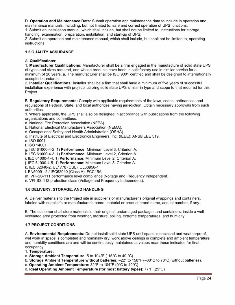
D. Operation and Maintenance Data: Submit operation and maintenance data to include in operation and maintenance manuals, including, but not limited to, safe and correct operation of UPS functions. 1. Submit an installation manual, which shall include, but shall not be limited to, instructions for storage, handling, examination, preparation, installation, and start-up of UPS. 2. Submit an operation and maintenance manual, which shall include, but shall not be limited to, operating instructions. 1.5 QUALITY ASSURANCE A. Qualifications: 1. Manufacturer Qualifications: Manufacturer shall be a firm engaged in the manufacture of solid state UPS of types and sizes required, and whose products have been in satisfactory use in similar service for a minimum of 20 years. a. The manufacturer shall be ISO 9001 certified and shall be designed to internationally accepted standards. 2. Installer Qualifications: Installer shall be a firm that shall have a minimum of five years of successful installation experience with projects utilizing solid state UPS similar in type and scope to that required for this Project. B. Regulatory Requirements: Comply with applicable requirements of the laws, codes, ordinances, and regulations of Federal, State, and local authorities having jurisdiction. Obtain necessary approvals from such authorities. 1. Where applicable, the UPS shall also be designed in accordance with publications from the following organizations and committees: a. National Fire Protection Association (NFPA). b. National Electrical Manufacturers Association (NEMA). c. Occupational Safety and Health Administration (OSHA). d. Institute of Electrical and Electronics Engineers, Inc. (IEEE); ANSI/IEEE 519. e. ISO 9001 f. ISO 14001 g. IEC 61000-4-2. 1) Performance: Minimum Level 3, Criterion A. h. IEC 61000-4-3. 1) Performance: Minimum Level 2, Criterion A. i. IEC 61000-4-4. 1) Performance: Minimum Level 2, Criterion A. j. IEC 61000-4-5. 1) Performance: Minimum Level 3, Criterion A. k. IEC 62040-2, UL1778 (CUL), UL60950-1 l. EN50091-2 / IEC62040 (Class A), FCC15A m. VFI-SS-111 performance level compliance (Voltage and Frequency Independent). n. VFI-SS-112 protection class (Voltage and Frequency Independent). 1.6 DELIVERY, STORAGE, AND HANDLING A. Deliver materials to the Project site in supplier’s or manufacturer’s original wrappings and containers, labeled with supplier’s or manufacturer’s name, material or product brand name, and lot number, if any. B. The customer shall store materials in their original, undamaged packages and containers, inside a well-ventilated area protected from weather, moisture, soiling, extreme temperatures, and humidity. 1.7 PROJECT CONDITIONS A. Environmental Requirements: Do not install solid state UPS until space is enclosed and weatherproof, wet work in space is completed and nominally dry, work above ceilings is complete and ambient temperature and humidity conditions are and will be continuously maintained at values near those indicated for final occupancy. 1. Temperature: a. Storage Ambient Temperature: 5 to 104°F (-15°C to 40 °C) b. Storage Ambient Temperature without batteries: –22° to 158°F (–30°C to 70°C) without batteries). c. Operating Ambient Temperature: 32°F to 104°F (0°C to 40°C) d. Ideal Operating Ambient Temperature (for most battery types): 77°F (25°C)

Page 25
2. Humidity: a. Relative Humidity: 0 percent to 95 percent. b. Operating Relative Humidity: 0 percent to 95 percent non-condensing. c. Altitude: Maximum installation with no derating of the UPS output shall be 3280 feet (1000 m) above sea level. The UPS capacity shall be derated for altitude as follows: 1) 4921 feet (1500 m), 95 percent load. 2) 6562 feet (2000 m), 91 percent load. 3) 8202 feet (2500 m), 86 percent load. 4) 9843 feet (3000 m), 82 percent load. 3. Audible Noise (As Measured 3 Feet [914 mm] From Surface):
a. At 480 Volt Operation (at 77 °F [25 °C]):
1) 54 dBA at 100 percent load. 2) 45 dBA at 70 percent load.
b. At 400 Volt Operation (at 77 °F [25 °C]): 1) 60 dBA at 100 percent load. 2) 49 dBA at 70 percent load. 1.8 WARRANTY A. Special Warranty: The Contractor shall warrant the work of this Section to be in accordance with the Contract Documents and free from faults and defects in materials and workmanship for period indicated below. This special warranty shall extend the one year period of limitations contained in the General Conditions. The special warranty shall be countersigned by the Installer and the manufacturer. 1. UPS Module: The UPS shall be covered by a full parts and labor warranty from the manufacturer for a period of 12 months from date of installation or acceptance by the Owner or 18 months from date of shipment from the manufacturer, whichever occurs first. B. Additional Owner Rights: The warranty shall not deprive the Owner of other rights the Owner may have under other provisions of the Contract Documents and shall be in addition to and run concurrent with other warranties made by the Contractor under requirements of the Contract Documents. 1.9 MAINTENANCE A. A complete offering of preventative and full service maintenance contracts for the UPS system and the battery system shall be available from the manufacturer. Contract work shall be performed by factory trained service personnel. PART 2 - PRODUCTS 2.1 MANUFACTURERS A. Basis of Design: Product specified is “APC Symmetra PX 250/500 kW” as manufactured by APC by Schneider Electric. Items specified are to establish a standard of quality for design, function, materials, and appearance. Equivalent products by other manufacturers are acceptable. The Architect/Engineer will be the sole judge of the basis of what is equivalent. 2.2 MODES OF OPERATION A. Normal: The PFC input stage and output inverter shall operate in an on-line manner to continuously regulate power to the critical load. The input and output converters shall be capable of full battery recharge while simultaneously providing regulated power to the load for all line and load conditions within the range of the UPS specifications. B. Battery: Upon failure of the AC input source, the critical load shall continue being supplied by the output inverter, which shall derive its power from the battery system. There shall be no interruption in power to the critical load during both transfers to battery operation and retransfers from battery to normal operation. Upon restoration of utility power to the UPS input, the UPS shall recharge the battery.

Page 26
C. Static Bypass: The static bypass shall be used to provide controller transfer of critical load from the inverter output to the bypass source. This transfer, along with its retransfer, shall take place with no power interruption to the critical load. In the event of a UPS output fault or significant output overload emergency, this transfer shall be an automatic function. Manual transfer to static bypass (called “requested bypass”) shall be available in order to facilitate a controlled transfer to maintenance bypass. [For parallel systems, the static bypass switches shall be installed in parallel.] D. Maintenance Bypass: The system shall be equipped with an optional integrated, bus connected external MBwD to electrically isolate the UPS during routine maintenance and service of the UPS. The MBwD shall allow for the completely electrical isolation of the UPS. An option for an external make-before-break external maintenance bypass panel shall be available. E. Parallel Operation: The system shall have the option to install up to four (4) UPSs in parallel configuration for redundancy or capacity. 1. The parallel UPS system shall be of the same design, voltage, and frequency. UPS modules of different size ratings shall be permitted to be paralleled together for purposes of increased capacity or UPS module redundancy. The UPSs in the parallel configuration shall not be required to have the same load capacity rating. 2. Parallel Capacity: With N+0 system-level redundancy, up to 2MW of load can be supported by the system. 3. Parallel Redundancy: With N+1 system-level redundancy, up to 1.5MW of load can be supported by the system, and only the UPS being replaced must be isolated from the source (bypass operation is not required for the entire system during the UPS replacement procedure). 4. Output control: A load sharing circuit shall be incorporated into the parallel control circuits to ensure that under no-load conditions, no circulating current exists between modules. This feature also allows each UPS to share equal amounts of the total critical load bus. The output voltage, output frequency, output phase angle, and output impedance of each module shall operate in uniformity to ensure correct load sharing. This control function shall not require any additional footprint and shall be an integral function of each UPS. The static bypass switches shall be connected in parallel. 5. Parallel System Controls: To avoid single points of failure, the UPS system shall have no single dedicated control system designed to control the operation of the parallel UPS system. Control of and direction of parallel UPSs shall take place via a master/slave relationship, where the first UPS to receive logic power asserts itself as a master. In the event of a master failure, a slave UPS shall take the role of master and assume the responsibility of the previous master UPS. Regardless of which UPS is master or slave, user changes to the system status, such as request for bypass, can be done from any UPS connected to the bus and all UPS on the bus shall transfer in simultaneously. 6. Communication: Communication between modules shall be connected so that the removal of any single cable shall not jeopardize the integrity of the parallel communication system. Load sharing communications shall be galvanically isolated for purposes of fault tolerance between UPS modules. A UPS module's influence over load sharing shall be inhibited in any mode where the UPS inverter is not supporting its output bus. Transfers to and from bypass can be initiated from any online UPS in the system. 7. Display: Each UPS multi-color LCD touch screen user interface shall be capable of using an active touch screen mimic bus to show the quantity of UPS(s) connected to the critical bus, as well as the general status of each UPS, such as circuit breaker status information. Any touchscreen display shall support the configuration of the [entire parallel] system and shall provide event and alarm data for all UPSs in the parallel configuration. A Virtual Display Application shall be available for download to the customer’s computer and shall support remote monitoring of a complete system with up to 4 UPSs in parallel. 8. Battery runtime: Each UPS must have its own battery solution. The battery solution for the entire system can be a combination of standard and third-party batteries, but each UPS must use only one battery solution – either standard or third-party batteries. 9. Switchgear: A custom switchgear option shall be required for parallel operation. F. External Sync: Synchronize the output of the UPS with any other independent source for use with downstream static transfer switches. The synchronization at the UPS is controlled from an input on the I/O relay board and can be controlled by a programmable logic controller. The source input is either connected to a terminal in the Maintenance Bypass with Distribution (MBwD) cabinet for a UPS with MBwD or to a terminal

Page 27
in the external switchgear controller for a UPS without MBwD. (Depending on the desired configuration, additional PLC hardware and programming may be required and shall be offered separately by APC.) G. MegaTie: The UPS or block of UPSs may have the ability to transfer the load between them without active load sharing. The Mega Tie mode will be active for 60 sec after it has been requested from a digital input on the relay board. The user has 60 seconds to transfer his load from one unit to another. After the 60 seconds, the UPS will automatically transfer back to normal operation. (Depending on the desired configuration, additional PLC hardware and programming may be required and shall be offered separately by APC.) H. EcoMode: In bypass operation, an even higher operating efficiency may be achieved without sacrificing protection when there are good power conditions. Depending on configuration, efficiency can exceed 99%.The load remains in bypass mode until the input voltage exceeds tolerance levels, and then enters full protection mode. UPS performance Class B cannot be guaranteed during short circuit error scenarios and other conditions. This setting is disabled by default and can be configured using the touchscreen display. 2.3 PFC INPUT STAGE A. General: The PFC input stage converters of the system shall be housed within the removable power modules, and the IGBT converters shall constantly control the power imported from the mains input of the system, to provide the necessary UPS power for precise regulation of the DC bus voltage, battery charging, and main inverter regulated output power. These power modules shall be connected in parallel within the UPS frame. B. Input Current Total Harmonic Distortion: The input current THDI shall be held to less than 5 percent at system load greater than 50 percent while providing conditioned power to the critical load bus, and charging the batteries under steady-state operating conditions. This shall be true while supporting both a linear or non-linear load. This shall be accomplished without the requirement for additional or optional filters, magnetic devices, or other components. C. Soft-Start Operation: As a standard feature, the UPS shall contain soft-start functionality, capable of limiting the input current from 0 percent to 100 percent of the nominal input over a default 10 second period, when returning to the AC utility source from battery operation. The change in current over the change in time shall take place in a linear manner throughout the entire operation. D. Magnetization Inrush Current: The UPS shall exhibit zero inrush current. The default soft start is 15 seconds. E. Input Current Limit: 1. The PFC input stage shall control and limit the input current draw from utility to 124 percent of the UPS output. During conditions where input current limit is active, the UPS shall be able to support 100 percent load at -15% utility power and no charge power. 2. In cases where the source voltage to the UPS is nominal and the applied UPS load is equal to or less than 100 percent of UPS capacity, input current shall not exceed 116 percent of UPS output current, while providing full battery recharge power and importing necessary power to account for system losses. F. Redundancy: The UPS shall be capable of being configured with redundant PFC input stages, each with semiconductor fusing, and logic-controlled contactors to isolate a failed module from the input bus. G. Charging: 1. The battery charging shall keep the DC bus float voltage of ±327 volts, ±1 percent. 2. The battery charging circuit shall contain a temperature compensation circuit, which shall regulate the battery charging to optimize battery life. 3. The battery charging circuit shall remain active when in static bypass and in normal operation. 4. The UPS shall be capable of reducing the battery charging current under low input voltage conditions as
long as utility power for the PFC is being provided. 5. Battery charge shall be limited to 10 percent of the system capacity by default (or optionally, 20% with
reduced load).

Page 28
6. The battery charging circuit will support boost, auto boost and equalization functions 7. An input connection will be provided that will allow the user to inhibit boost charging. 8. The UPS shall be capable of reducing the battery charging current down to zero based on user defined
input. H. Back-Feed Protection: The above mentioned logic-controlled contactor shall also provide the back-feed protection required by UL 1778. 2.4 OUTPUT INVERTER A. General: The UPS output inverter shall constantly develop the UPS output voltage waveform by converting the DC bus voltage to AC voltage through a set of IGBT driven bi-directional power converters. In both normal operation and battery operation, the output inverters shall create an output voltage independent of the mains input voltage. Input voltage anomalies such as brown-outs, spikes, surges, sags, and outages shall not affect the amplitude or sinusoidal nature of the output voltage sine wave of the inverters. B. Overload Capability: The output power converters shall be capable of 230 percent for short circuit clearing. Steady-state overload conditions of up to 150 percent of system capacity shall be sustained by the inverter for 60 seconds in normal operation. Steady-state overload conditions of up to 125 percent of system capacity shall be sustained by the inverter for 10 minutes in normal operation. Overloads persisting past the outlined time limitation the critical load shall be switched to the automatic static bypass output of the UPS. C. Output Contactor: The output inverter shall be provided with an output mechanical contactor to provide physical isolation of the inverter from the critical bus. With this feature a failed inverter shall be isolated from the critical bus. D. Battery Protection: The inverter shall be provided with monitoring and control circuits to limit the level of discharge on the battery system. E. Redundancy: The UPS shall be capable of being configured with redundant output inverters, each with semiconductor fusing, and logic-controlled contactors to remove a failed component from the input, DC, and output critical bus. 2.5 STATIC BYPASS A. General: As part of the UPS, a system static bypass module shall be provided. The system static bypass shall be hot swappable and provide no break transfer of the critical load from the inverter output to the static bypass input source during times where maintenance is required, or the inverter cannot support the critical bus. Such times may be due to prolonged or severe overloads, or UPS failure. The UPS and static bypass module shall constantly monitor the auxiliary contacts of their respective circuit breakers, as well as the bypass source voltage, and inhibit potentially unsuccessful transfers to static bypass from taking place. B. Design: The design of the static switch power path shall consist of silicon-controlled rectifiers (SCR) with a continuous duty rating of 125 percent of the UPS output rating for 480 V systems and 110% for 400/415 V systems. C. Automatic Transfers: An automatic transfer of load to static bypass shall take place whenever the load on the critical bus exceeds the overload rating of the UPS. Automatic transfers of the critical load from static bypass back to normal operation shall take place when the overload condition is removed from the critical output bus of the system. Automatic transfers of load to static bypass shall also take place if for any reason the UPS cannot support the critical bus. D. Manual Transfers: Manually initiated transfers to and from static bypass shall be initiated through the UPS graphical user interface. [For parallel configurations, transfers to and from bypass can be initiated from any online UPS in the system.]

Page 29
E. Overloads: For 480V systems, the static bypass shall be rated and capable of handling overloads equal to or less than 125 percent of the rated system output continuously. For 400/415V systems, the static bypass shall be rated and capable of handling overloads equal to or less than 110 percent of the rated system output continuously. For instantaneous overloads caused by inrush current from magnetic devices, or short circuit conditions, the static bypass shall be capable of sustaining overloads of 1000 percent of system capacity for periods of up to 100 milliseconds. F. Modular: The static bypass switch shall be of a modular design. G. System Protection: As a requirement of UL 1778, back-feed protection in the static bypass circuit shall also be incorporated in the system design. To achieve back-feed protection, a mechanical contactor in series with the bypass SCR(s) shall be controlled by the UPS/static switch, to open immediately upon sensing a condition where back-feeding of the static switch by any source connected to the critical output bus of the system is occurring. One such condition could be a result of a shorted SCR. H. Static Switch: For parallel systems, static switch design shall be distributed/integral type. External static switch cabinets shall not be necessary. 2.6 DISPLAY AND CONTROLS A. Control Logic: The UPS shall be controlled by two fully redundant, owner-replaceable and hot-swappable intelligence modules (IM). These modules shall have separate, optically isolated, communication paths to the power and static switch modules. Logic power for the control modules shall be derived from redundant power supplies, each having a separate AC and DC input and output. The communication of the control modules shall be of controller area network (CAN Bus) and EIA485. All control functions such as start-up, transfer to bypass, and all parameter changes shall be accessible from the touch screen user interface. Operations such as start-up will have step by step instructions from the user interface to ensure correct sequencing of operations. To further minimize user error, the touch screen shall highlight, in green, all functions that have been completed. The current step in the process shall also be outlined to ensure easy operation. Each UPS system shall have one such user interface. B. Graphical User Interface: A microprocessor-controlled user interface/display unit shall be located on the front of the system. The display shall consist of a 10.4 inch (264 mm) multicolor graphical display with 800 x 600 resolution. The display shall be localized into the following languages: 1. Brazilian Portuguese 2. Chinese 3. French 4. German 5. Korean 6. Russian 7. Spanish C. Virtual Display: Download the display interface to your laptop or personal computer and monitor a complete system with up to 4 UPSs in parallel. Alarms and events are linked directly to the specific location shown in a picture of the actual customer setup. The interface matches the touchscreen display interface and supports the configuration of the following parameters: 1. Battery Test schedule settings and request of battery test 2. Alarm threshold settings 3. NMC settings 4. System settings - names, date and time 5. Predictive Maintenance settings of door filter

Page 30
D. Metered Data: The following data shall be available on the graphical user interface/display: 1. Input/output voltages, currents, frequencies. 2. Breaker and switch status. 3. Battery status. 4. Event log. 5. Energy measurements. E. Event Log: The display unit shall allow the Owner to display a time and date stamped log. The event log shall be capable of holding 1500 entries. The default event log size shall be 400 entries. F. Alarms: The display unit shall allow the Owner to display a log of active alarms. The following minimum set of alarm conditions shall be available: 1. Input frequency outside configured range. 2. AC adequate for UPS but not for bypass. 3. Low/no AC input, startup on battery. 4. Intelligence module inserted. 5. Intelligence module removed. 6. Redundant intelligence module inserted. 7. Redundant intelligence module removed. 8. Number of batteries changed since last on. 9. Number of power modules changed since last on. 10. Number of batteries increased. 11. Number of batteries decreased. 12. Number of power modules increased. 13. Number of power modules decreased. 14. Number of external battery cabinets increased. 15. Number of external battery cabinets decreased. 16. Redundancy restored. 17. Need battery replacement. 18. The redundant intelligence module is in control. 19. UPS fault. 20. On battery. 21. Shutdown or unable to transfer to battery due to overload. 22. Load shutdown from bypass. input frequency, volts outside limits. 23. Fault, internal temperature exceeded system normal limits. 24. Input circuit breaker open. 25. System level fan failed. 26. Bad battery module. 27. Bad power module. 28. Intelligence module installed and failed. 29. Redundant intelligence module installed and failed. 30. Redundancy lost. 31. Redundancy below alarm threshold. 32. Runtime below alarm threshold. 33. Load above alarm threshold. 34. Sub feed breaker above critical level 35. Load no longer above alarm threshold. 36. Minimum runtime restored. 37. Bypass not in range (either frequency or voltage). 38. Back-feed contactor stuck in off position. 39. Back-feed contactor stuck in on position. 40. UPS in bypass due to internal fault. 41. UPS in bypass due to overload. 42. System in forced bypass. 43. Fault bypass relay malfunction. 44. Q001 open/closed. 45. Q002 open/closed.
Page 31
46. Q003 open/closed. 47. Q005 open/closed. 48. High DC warning. 49. High DC shutdown. 50. Low battery shutdown. 51. Low battery warning. 52. MBwD door open. 53. Parallel communication error G. Controls: The following controls or programming functions shall be accomplished by the use of the user interface/display unit. The touch screen display shall facilitate these operations: 1. Silence audible alarm. 2. Display or set the date and time. 3. Enable or disable the automatic restart feature. 4. Transfer critical load to and from static bypass. 5. Test battery condition on demand. 6. Set intervals for automatic battery tests. 7. Adjust set points for different alarms. 8. Adjustable ramp-in times from 1 to 40 seconds. 9. Potential free (dry) contacts. H. Potential Free Contacts or Dry Contacts: The following potential free contacts shall be available on the relay interface board: 1. Normal operation. 2. Battery operation. 3. Bypass operation. 4. Common fault. 5. Low battery. 6. UPS off. I. Communication Interface Board: A communication interface board shall provide the following communication ports which shall be able to be used simultaneously: 1. Ethernet. 2. Ethernet interface port for a remote display. 3. Modbus RS485 J. Emergency power off (EPO) (Note: The EPO pushbutton shall include a protective cover to prevent unintentional operation). 2.7 BATTERY A. The UPS battery shall support an optional battery plant of modular construction made up of Owner-replaceable, hot-swappable, fused, battery modules. Each battery module shall be monitored for voltage and temperature for use by the UPS battery diagnostic. Battery charging current shall be temperature compensated. It should also be possible to cyclic charge the batteries with programmable charge and rest time. B. The battery jars housed within each removable battery module shall be of the valve regulated lead acid (VRLA) type. C. The UPS shall incorporate a battery management system to continuously monitor the status of each removable battery module. This system shall notify the Owner in the event a failed or weak battery module is found. D. The batteries shall have a design life of 5 to 8 years and a battery service life of 3 to 5 years. The battery casing shall be flame retardant type.
Page 32
E. The UPS shall incorporate a battery capacity test that will be capable of determining available runtimes. 2.8 ACCESSORIES A. Battery Breaker Cabinet: To facilitate third party battery configuration including wet cell batteries, a battery breaker cabinet in a line-up and match net shelter enclosure shall be available. Each cabinet shall monitor breaker status and battery temperature. Each circuit breaker shall be equipped shunt trip mechanisms and 1A/1B auxiliary contacts. The battery breaker cabinet shall accommodate top or bottom entry for cables. The cell number count shall be adjustable from 138 to 150 from the user display with the default cell count set at 144. B. Optional Maintenance Bypass Cabinet (MBwD): 1. The MBwD shall provide power to the critical load bus from the bypass source, during times where maintenance or service of the UPS is required. The MBwD shall provide a mechanical means of complete isolation of the UPS from the electrical wiring of the installation and shall be mounted to the systems I/O frame. As a minimum, the MBwD shall contain the following features and accessories: a. Subfeed circuit breakers of the appropriate size, withstand rating (see table), and trip rating for the system. Other breaker sizes and withstand ratings shall be available as custom options. Breaker size Interrupt rating 60-100A 22,000AIC 125-400A 25,000AIC T-1, T-3, and T-5 breakers shall be supported.

Page 33
6.2 BASIS OF DESIGN: Location- Sprung Structure – North Electrical Room One (1) APC Three Phase Uninterruptible Power Supply, model name APC Symmetra, with the following features and characteristics: The following basis of Design very closely approximates the Owner’s requirements, but may not completely reflect all features necessary for turn-key operation. Contractor shall verify and provide all required.
APC by Schneider Electric APC SYMMETRA PX 250/500 kW [Parallel] [Single UPS (100kW to 500kW)] [Parallel UPSs (100kW to 2MW)] Uninterruptible Power Supply THIS GUIDE SPECIFICATION IS WRITTEN IN ACCORDANCE WITH THE CONSTRUCTION SPECIFICATIONS INSTITUTE (CSI) MASTERFORMAT. THIS SECTION MUST BE CAREFULLY REVIEWED AND EDITED BY THE ARCHITECT OR THE ENGINEER TO MEET THE REQUIREMENTS OF THE PROJECT. COORDINATE THIS SECTION WITH OTHER SPECIFICATION SECTIONS IN THE PROJECT MANUAL AND WITH THE DRAWINGS. WHERE REFERENCE IS MADE THROUGHOUT THIS SECTION TO “PROVIDE”, “INSTALL”, “SUBMIT”, ETC., IT SHALL MEAN THAT THE CONTRACTOR, SUBCONTRACTOR, OR CONTRACTOR OF LOWER TIER SHALL “PROVIDE”, “INSTALL”, SUBMIT”, ETC., UNLESS OTHERWISE INDICATED. THIS SECTION IS WRITTEN TO INCLUDE THE 2004 MASTERFORMAT AND THE 1995 MASTERFORMAT VERSIONS. WHERE APPLICABLE, THESE ITEMS ARE BRACKETED AND, IN EACH CASE, UNLESS OTHERWISE INDICATED, THE FIRST CHOICE APPLIES TO THE 2004 MASTERFORMAT AND THE SECOND CHOICE APPLIES TO THE 1995 MASTERFORMAT. SECTION [26 33 53] [16611] STATIC UNINTERRUPTIBLE POWER SUPPLY PART 1 - GENERAL 1.1 SUMMARY A. Scope: Provide design and engineering, labor, material, equipment, related services, and supervision required, including, but not limited to, manufacturing, fabrication, erection, and installation for a static uninterruptible power supply (UPS) as required for the complete performance of the work and as shown on the Drawings and as herein specified. B. Section Includes: The work specified in this Section includes, but shall not be limited to, a continuous duty, three-phase, solid state, on-line double conversion static UPS. 1. The UPS shall utilize a rack-mounted N+0 redundant, scalable array architecture. The system power train shall be comprised of 25 kVA/25 kW power modules and shall be capable of being configured for N+0 redundant operation at the rated system load. [In systems operating at a load where the system has N+0 module-level redundancy or greater, the UPS shall facilitate the replacement of power modules while the system remains in normal operation, without the requirement to transfer to bypass (hot swappable power modules).] [In parallel systems operating at a load where the system has N+0 system-level redundancy or greater, the parallel configuration shall facilitate the replacement of individual UPSs while the system remains in normal operation, without the requirement to transfer to bypass.] 2. Each hot-swappable/user replaceable 25 kVA/25 kW power module shall contain a fully rated, power factor corrected input rectifier/boost converter hereafter referred to as the PFC input stage, a fully rated output inverter, battery charging circuit and field replaceable fans. Power module fans shall be variable speed controlled and capable of maintaining the system in the event of a single fan failure. The system shall also be comprised of a hot swappable continuous duty bypass static switch module, redundant control modules, redundant logic power supplies, and touch screen user interface/display. Hot swappable/user-replaceable battery modules shall be available as an option. 3. All of the above system components shall be housed in a standard APC NetShelter SX Racks with one of the following dimensions: a. 600 mm wide by 1070 mm deep by 2000 mm high (I/O Frame or Power Frame) b. 750 mm wide by 1070 mm deep by 2000 mm high (Battery Frame] c. 300 mm wide by 1070 mm deep by 2000 mm high (optional Battery Side Car or optional Bottom Feed Frame)

Page 34
d. 1000 mm wide by 1070 mm deep by 2000 mm high (optional I/O Frame with Maintenance Bypass with Distribution). [Maintenance Bypass Panels for parallel systems will be customized and will have custom dimensions based on the configuration.] The racks shall require no rear access for maintenance. 4. In addition, this Section describes the performance, functionality, and design of the optional UPS maintenance bypass cabinet with output distribution, hereafter referred to as the MBwD and the battery system. The MBwD shall not be included or supported by UPSs in parallel configurations. 5. The UPS and associated equipment shall operate in conjunction with a primary power supply and an output distribution system to provide quality uninterrupted power for mission critical, electronic equipment load. 6. All programming and miscellaneous components for a fully operational system as described in this Section shall be available as part of the UPS. 1.2 REFERENCES A. General: The publications listed below form a part of this Specification to the extent referenced. The publications are referred to in the text by the basic designation only. The edition/revision of the referenced publications shall be the latest date as of the date of the Contract Documents, unless otherwise specified. B. Institute of Electrical and Electronics Engineers, Inc. (IEEE): 1. ANSI/IEEE 519, "Guide for Harmonic Control and Reactive Compensation of Static Power Converters" (copyrighted by IEEE, ANSI approved). C. International Organization for Standardization (ISO): 1. ISO 9001, "Quality Management Systems - Requirements." 2. ISO 14001, “Environmental Management Systems - Requirements with Guidance for Use.” 1.3 [PARALLEL] SYSTEM DESCRIPTION A. Design Requirements: INSERT APPLICABLE VALUES IN SUBPARAGRAPHS BELOW. 1. The UPS shall be sized for [125] kVA and [125] kW load. 2. [The parallel system shall be comprised of [(5) 25KW] UPSs for N+ [0] system-level redundancy.] 3. [The parallel system shall be sized for [125] kVA and [125] kW load.] 4. The UPS battery shall be sized for [125] kVA at a power factor of [unity power factor] for [6] minutes. B. System Characteristics: 1. System Capacity: The system shall be rated for full kW output in the following frame sizes: a. 250 kVA/kW—can be configured with up to ten (10) 25 kW power modules for 250 kW N+0 or 225 kW N+1 module-level redundancy. b. 500 kVA/kW—can be configured with up to twenty (20) 25 kW modules for 500 kW N+0 or 475 kW N+1 module-level redundancy c. [2MW—can be configured with 25kW power modules for up to 2MW N+0 redundancy or up to 1.5MW N+1 system-level redundancy]

Page 35
2. Input: The system input shall be configurable as either single or dual mains derived from a three phase wye source. Standard cable entry shall be through the top. Bottom cable entry shall also be facilitated. Depending on the specific configuration, the use of the optional bottom feed enclosure may be required. An option shall be available to facilitate the connection of NEMA 2 compression lugs for main input, bypass input, DC input, and output cable connections. a. AC Input Nominal Voltage: System voltage shall support 3-phase + neutral + ground or 3-phase + ground in a dual or single mains configuration and be selectable at the front panel by service personnel with the following options: 1) 380 volts, 400 volts, 415 volts, and 480 volts. b. AC Input Voltage Window: 1) ±15 percent for full performance (340 to 460 volts at 400 volts, 408 volts to 552 volts at 480 volts). 2) -50 percent for reduced load (200 volts at 400 volts, 240 volts at 480 volts). c. Short Circuit Withstand Rating: 1) UPS: 65,000 Symmetrical Amperes 2) Optional Maintenance Bypass with Distribution Panel: 50,000 Symmetrical Amperes or lowest rated
subfeed circuit breaker 3) Custom Switchgear: 65,000 Symmetrical Amperes or as specified 4) Lowest Rated Subfeed Circuit Breaker (60-100A) for MBwD: 22,000 Symmetrical Amperes
5) Lowest Rated Subfeed Circuit Breaker (125-400A) for MBwD: 25,000 Symmetrical Amperes 6) Custom Subfeed Circuit Breakers for MBwD: Subfeed circuit breakers with a short circuit withstand
rating greater than 22,000 Symmetrical Amperes or 25,000 Symmetrical Amperes shall be available as a custom option.
d. Maximum Frequency Range: 40 to 70 hertz. 1) Frequency shall be synchronized to bypass input when available over the standard range of 57 to 63
hertz. Optional frequency tolerance range shall be configurable from 0.5 percent to 8 percent from front panel. Default shall be +/-1% (+/-0.6Hz at 60Hz).
e. Input Power Factor: 1) Greater than 0.995 with load at 100 percent. 2) Greater than 0.99 with loads above 50 percent. 3) Greater than 0.97 with loads above 25 percent. f. Input Current in Normal Operation: 1) As a percentage of output current, with no charging, will be limited to a maximum of 105 percent of system capacity. g. Input Current Distortion with No Additional Filters: 1) Less than 5 percent. h. Soft-Start: 1) Shall be linear from 0 percent to 100 percent input current and shall not exhibit inrush. This shall take place over an Owner-selectable 1 second to 40 second time period with a factory default of 15 seconds. i. Symmetra PX 250/500 kW 480 V is OSHPD pre-approved 3. UPS Output: a. AC Output Nominal Output: System voltage shall support 3-phases + neutral + ground or 3-phases + ground are selectable at the graphical user interface by service personnel with the following options: 1) 380 volts, 400 volts, 415 volts, and 480 volts. b. AC Output Voltage Distortion: Less than 2 percent at 100 percent linear load, less than 3 percent for SMPS load as defined by IEC 62040-3. c. AC Output Voltage Regulation: ±1 percent for 100 percent linear or non-linear load. d. Voltage Transient Response: ±5 percent maximum RMS change in a half cycle at load step 0 percent to 100 percent or 100 percent to 0 percent. e. Voltage Transient Recovery: Within less than 50 milliseconds. f. Output Voltage Harmonic Distortion: Less than 2 percent from 0 to 100% load. Less than 3 percent full non-linear load according to IEC/EN62040-3. g. Overload Rating: 1) Normal Operation: a) 150 percent for 60 seconds before transfer to bypass. b) 125 percent for 10 minutes before transfer to bypass. 2) Battery Operation: 125 percent for 30 seconds (up to 10 minutes with fully configured battery solution)

Page 36
3) Bypass Operation: a) 125 percent continuous at 480 volts. b) 110 percent continuous at 400 volts c) 1000 percent for 100 milliseconds. h. System AC-AC Efficiency: 1) Normal operation greater than 96 percent at 40 percent to 100 percent load. 2) Battery operation greater than 95 percent at 40 percent to 100 percent load. i. Output Power Factor Rating: 0.5 leading to 0.5 lagging without any derating. 4. Charge current: a. 20% of charging capacity when the load is less than 90% b. 10% of charging capacity with 100% load 5. Parallel cabling: a. The standard cable distance shall be 25m (81.3ft) b. Custom cables of other lengths shall be accommodated. c. The maximum cable distance shall be 75m (244ft) across all UPSs in the installation. 6. Regulatory compliance: The UPS shall comply with the following standards:
a. Underwriters Laboratories, Inc. (UL):
1) UL 891, "Standard for Dead-Front Switchboards" (copyrighted by UL, ANSI approved). 2) UL 1558, "Standard for Metal-Enclosed Low-Voltage Power Circuit Breaker Switchgear." 3) UL 1778, "Standard for Uninterruptible Power Supply Equipment" (copyrighted by UL, ANSI approved). 4) UL 60950, “Standard for Information Technology Equipment.” 5) CSA C22.2 No.107.3-05 Uninterruptible Power Systems b. International Electrotechnical Commission (IEC): 1) IEC 61000-4-2, “Electromagnetic Compatibility - Testing and Measurement Techniques; Electrostatic Discharge Immunity Test.” 2) IEC 61000-4-3, “Electromagnetic Compatibility - Testing and Measurement Techniques; Radiated, Radio Frequency, Electromagnetic Field Immunity Test.” 3) IEC 61000-4-4, “Electromagnetic Compatibility - Testing and Measurement Techniques; Electrical Fast Transient/Burst Immunity Test.” 4) IEC 61000-4-5, “Electromagnetic Compatibility - Testing and Measurement Techniques; Surge Immunity Test.” 5) IEC 62040-2, “Uninterruptible Power Systems - Electromagnetic Compatibility (EMC) Requirements,” 6) IEC 62040-3, “Uninterruptible Power Systems - Method of Specifying the Performance and Test Requirements.” 1.4 SUBMITTALS A. Product Data: Submit product data showing material proposed. Submit sufficient information to determine compliance with the Drawings and Specifications. Product data shall include, but shall not be limited to, the following: 1. As bid system bill of materials. 2. Product catalog sheets or equipment brochures. 3. Product guide specifications. B. Shop Drawings: Submit shop drawings for each product and accessory required. Include information not fully detailed in manufacturer’s standard product data, including, but not limited to, the following: 1. Installation information, including, but not limited to, weights and dimensions. 2. Information about terminal locations for power and control connections. 3. Drawings for requested optional accessories.

Page 37
C. Wiring Diagrams: Submit wiring diagrams detailing power, signal, and control systems, clearly differentiating between manufacturer-installed wiring and field-installed wiring, and between components provided by the manufacturer and those provided by others. 1. Submit system single-line operation diagram. D. Operation and Maintenance Data: Submit operation and maintenance data to include in operation and maintenance manuals, including, but not limited to, safe and correct operation of UPS functions. 1. Submit an installation manual, which shall include, but shall not be limited to, instructions for storage, handling, examination, preparation, installation, and start-up of UPS. 2. Submit an operation and maintenance manual, which shall include, but shall not be limited to, operating instructions. 1.5 QUALITY ASSURANCE A. Qualifications: 1. Manufacturer Qualifications: Manufacturer shall be a firm engaged in the manufacture of solid state UPS of types and sizes required, and whose products have been in satisfactory use in similar service for a minimum of 20 years. a. The manufacturer shall be ISO 9001 certified and shall be designed to internationally accepted standards. 2. Installer Qualifications: Installer shall be a firm that shall have a minimum of five years of successful installation experience with projects utilizing solid state UPS similar in type and scope to that required for this Project. B. Regulatory Requirements: Comply with applicable requirements of the laws, codes, ordinances, and regulations of Federal, State, and local authorities having jurisdiction. Obtain necessary approvals from such authorities. 1. Where applicable, the UPS shall also be designed in accordance with publications from the following organizations and committees: a. National Fire Protection Association (NFPA). b. National Electrical Manufacturers Association (NEMA). c. Occupational Safety and Health Administration (OSHA). d. Institute of Electrical and Electronics Engineers, Inc. (IEEE); ANSI/IEEE 519. e. ISO 9001 f. ISO 14001 g. IEC 61000-4-2. 1) Performance: Minimum Level 3, Criterion A. h. IEC 61000-4-3. 1) Performance: Minimum Level 2, Criterion A. i. IEC 61000-4-4. 1) Performance: Minimum Level 2, Criterion A. j. IEC 61000-4-5. 1) Performance: Minimum Level 3, Criterion A. k. IEC 62040-2, UL1778 (CUL), UL60950-1 l. EN50091-2 / IEC62040 (Class A), FCC15A m. VFI-SS-111 performance level compliance (Voltage and Frequency Independent). n. VFI-SS-112 protection class (Voltage and Frequency Independent). 1.6 DELIVERY, STORAGE, AND HANDLING A. Deliver materials to the Project site in supplier’s or manufacturer’s original wrappings and containers, labeled with supplier’s or manufacturer’s name, material or product brand name, and lot number, if any. B. The customer shall store materials in their original, undamaged packages and containers, inside a well-ventilated area protected from weather, moisture, soiling, extreme temperatures, and humidity.
Page 38
1.7 PROJECT CONDITIONS A. Environmental Requirements: Do not install solid state UPS until space is enclosed and weatherproof, wet work in space is completed and nominally dry, work above ceilings is complete and ambient temperature and humidity conditions are and will be continuously maintained at values near those indicated for final occupancy. 1. Temperature: a. Storage Ambient Temperature: 5 to 104°F (-15°C to 40 °C) b. Storage Ambient Temperature without batteries: –22° to 158°F (–30°C to 70°C) without batteries). c. Operating Ambient Temperature: 32°F to 104°F (0°C to 40°C) d. Ideal Operating Ambient Temperature (for most battery types): 77°F (25°C) 2. Humidity: a. Relative Humidity: 0 percent to 95 percent. b. Operating Relative Humidity: 0 percent to 95 percent non-condensing. c. Altitude: Maximum installation with no derating of the UPS output shall be 3280 feet (1000 m) above sea level. The UPS capacity shall be derated for altitude as follows: 1) 4921 feet (1500 m), 95 percent load. 2) 6562 feet (2000 m), 91 percent load. 3) 8202 feet (2500 m), 86 percent load. 4) 9843 feet (3000 m), 82 percent load. 3. Audible Noise (As Measured 3 Feet [914 mm] From Surface):
a. At 480 Volt Operation (at 77 °F [25 °C]):
1) 54 dBA at 100 percent load. 2) 45 dBA at 70 percent load.
b. At 400 Volt Operation (at 77 °F [25 °C]): 1) 60 dBA at 100 percent load. 2) 49 dBA at 70 percent load. 1.8 WARRANTY A. Special Warranty: The Contractor shall warrant the work of this Section to be in accordance with the Contract Documents and free from faults and defects in materials and workmanship for period indicated below. This special warranty shall extend the one year period of limitations contained in the General Conditions. The special warranty shall be countersigned by the Installer and the manufacturer. 1. UPS Module: The UPS shall be covered by a full parts and labor warranty from the manufacturer for a period of 12 months from date of installation or acceptance by the Owner or 18 months from date of shipment from the manufacturer, whichever occurs first. B. Additional Owner Rights: The warranty shall not deprive the Owner of other rights the Owner may have under other provisions of the Contract Documents and shall be in addition to and run concurrent with other warranties made by the Contractor under requirements of the Contract Documents. 1.9 MAINTENANCE A. A complete offering of preventative and full service maintenance contracts for the UPS system and the battery system shall be available from the manufacturer. Contract work shall be performed by factory trained service personnel. PART 2 - PRODUCTS 2.1 MANUFACTURERS A. Basis of Design: Product specified is “APC Symmetra PX 250/500 kW” as manufactured by APC by Schneider Electric. Items specified are to establish a standard of quality for design, function, materials, and appearance. Equivalent products by other manufacturers are acceptable. The Architect/Engineer will be the sole judge of the basis of what is equivalent.

Page 39
2.2 MODES OF OPERATION A. Normal: The PFC input stage and output inverter shall operate in an on-line manner to continuously regulate power to the critical load. The input and output converters shall be capable of full battery recharge while simultaneously providing regulated power to the load for all line and load conditions within the range of the UPS specifications. B. Battery: Upon failure of the AC input source, the critical load shall continue being supplied by the output inverter, which shall derive its power from the battery system. There shall be no interruption in power to the critical load during both transfers to battery operation and retransfers from battery to normal operation. Upon restoration of utility power to the UPS input, the UPS shall recharge the battery. C. Static Bypass: The static bypass shall be used to provide controller transfer of critical load from the inverter output to the bypass source. This transfer, along with its retransfer, shall take place with no power interruption to the critical load. In the event of a UPS output fault or significant output overload emergency, this transfer shall be an automatic function. Manual transfer to static bypass (called “requested bypass”) shall be available in order to facilitate a controlled transfer to maintenance bypass. [For parallel systems, the static bypass switches shall be installed in parallel.] D. Maintenance Bypass: The system shall be equipped with an optional integrated, bus connected external MBwD to electrically isolate the UPS during routine maintenance and service of the UPS. The MBwD shall allow for the completely electrical isolation of the UPS. An option for an external make-before-break external maintenance bypass panel shall be available. E. Parallel Operation: The system shall have the option to install up to four (4) UPSs in parallel configuration for redundancy or capacity. 1. The parallel UPS system shall be of the same design, voltage, and frequency. UPS modules of different size ratings shall be permitted to be paralleled together for purposes of increased capacity or UPS module redundancy. The UPSs in the parallel configuration shall not be required to have the same load capacity rating. 2. Parallel Capacity: With N+0 system-level redundancy, up to 2MW of load can be supported by the system. 3. Parallel Redundancy: With N+1 system-level redundancy, up to 1.5MW of load can be supported by the system, and only the UPS being replaced must be isolated from the source (bypass operation is not required for the entire system during the UPS replacement procedure). 4. Output control: A load sharing circuit shall be incorporated into the parallel control circuits to ensure that under no-load conditions, no circulating current exists between modules. This feature also allows each UPS to share equal amounts of the total critical load bus. The output voltage, output frequency, output phase angle, and output impedance of each module shall operate in uniformity to ensure correct load sharing. This control function shall not require any additional footprint and shall be an integral function of each UPS. The static bypass switches shall be connected in parallel. 5. Parallel System Controls: To avoid single points of failure, the UPS system shall have no single dedicated control system designed to control the operation of the parallel UPS system. Control of and direction of parallel UPSs shall take place via a master/slave relationship, where the first UPS to receive logic power asserts itself as a master. In the event of a master failure, a slave UPS shall take the role of master and assume the responsibility of the previous master UPS. Regardless of which UPS is master or slave, user changes to the system status, such as request for bypass, can be done from any UPS connected to the bus and all UPS on the bus shall transfer in simultaneously. 6. Communication: Communication between modules shall be connected so that the removal of any single cable shall not jeopardize the integrity of the parallel communication system. Load sharing communications shall be galvanically isolated for purposes of fault tolerance between UPS modules. A UPS module's influence over load sharing shall be inhibited in any mode where the UPS inverter is not supporting its output bus. Transfers to and from bypass can be initiated from any online UPS in the system.

Page 40
7. Display: Each UPS multi-color LCD touch screen user interface shall be capable of using an active touch screen mimic bus to show the quantity of UPS(s) connected to the critical bus, as well as the general status of each UPS, such as circuit breaker status information. Any touchscreen display shall support the configuration of the [entire parallel] system and shall provide event and alarm data for all UPSs in the parallel configuration. A Virtual Display Application shall be available for download to the customer’s computer and shall support remote monitoring of a complete system with up to 4 UPSs in parallel. 8. Battery runtime: Each UPS must have its own battery solution. The battery solution for the entire system can be a combination of standard and third-party batteries, but each UPS must use only one battery solution – either standard or third-party batteries. 9. Switchgear: A custom switchgear option shall be required for parallel operation. F. External Sync: Synchronize the output of the UPS with any other independent source for use with downstream static transfer switches. The synchronization at the UPS is controlled from an input on the I/O relay board and can be controlled by a programmable logic controller. The source input is either connected to a terminal in the Maintenance Bypass with Distribution (MBwD) cabinet for a UPS with MBwD or to a terminal in the external switchgear controller for a UPS without MBwD. (Depending on the desired configuration, additional PLC hardware and programming may be required and shall be offered separately by APC.) G. MegaTie: The UPS or block of UPSs may have the ability to transfer the load between them without active load sharing. The Mega Tie mode will be active for 60 sec after it has been requested from a digital input on the relay board. The user has 60 seconds to transfer his load from one unit to another. After the 60 seconds, the UPS will automatically transfer back to normal operation. (Depending on the desired configuration, additional PLC hardware and programming may be required and shall be offered separately by APC.) H. EcoMode: In bypass operation, an even higher operating efficiency may be achieved without sacrificing protection when there are good power conditions. Depending on configuration, efficiency can exceed 99%.The load remains in bypass mode until the input voltage exceeds tolerance levels, and then enters full protection mode. UPS performance Class B cannot be guaranteed during short circuit error scenarios and other conditions. This setting is disabled by default and can be configured using the touchscreen display. 2.3 PFC INPUT STAGE A. General: The PFC input stage converters of the system shall be housed within the removable power modules, and the IGBT converters shall constantly control the power imported from the mains input of the system, to provide the necessary UPS power for precise regulation of the DC bus voltage, battery charging, and main inverter regulated output power. These power modules shall be connected in parallel within the UPS frame. B. Input Current Total Harmonic Distortion: The input current THDI shall be held to less than 5 percent at system load greater than 50 percent while providing conditioned power to the critical load bus, and charging the batteries under steady-state operating conditions. This shall be true while supporting both a linear or non-linear load. This shall be accomplished without the requirement for additional or optional filters, magnetic devices, or other components. C. Soft-Start Operation: As a standard feature, the UPS shall contain soft-start functionality, capable of limiting the input current from 0 percent to 100 percent of the nominal input over a default 10 second period, when returning to the AC utility source from battery operation. The change in current over the change in time shall take place in a linear manner throughout the entire operation. D. Magnetization Inrush Current: The UPS shall exhibit zero inrush current. The default softstart is 15 seconds. E. Input Current Limit: 1. The PFC input stage shall control and limit the input current draw from utility to 124 percent of the UPS output. During conditions where input current limit is active, the UPS shall be able to support 100 percent load at -15% utility power and no charge power.

Page 41
2. In cases where the source voltage to the UPS is nominal and the applied UPS load is equal to or less than 100 percent of UPS capacity, input current shall not exceed 116 percent of UPS output current, while providing full battery recharge power and importing necessary power to account for system losses. F. Redundancy: The UPS shall be capable of being configured with redundant PFC input stages, each with semiconductor fusing, and logic-controlled contactors to isolate a failed module from the input bus. G. Charging: 1. The battery charging shall keep the DC bus float voltage of ±327 volts, ±1 percent. 2. The battery charging circuit shall contain a temperature compensation circuit, which shall regulate the battery charging to optimize battery life. 3. The battery charging circuit shall remain active when in static bypass and in normal operation. 4. The UPS shall be capable of reducing the battery charging current under low input voltage conditions as long as utility power for the PFC is being provided. 5. Battery charge shall be limited to 10 percent of the system capacity by default (or optionally, 20% with reduced load). 6. The battery charging circuit will support boost, auto boost and equalization functions 7. An input connection will be provided that will allow the user to inhibit boost charging. 8. The UPS shall be capable of reducing the battery charging current down to zero based on user defined input. H. Back-Feed Protection: The above mentioned logic-controlled contactor shall also provide the back-feed protection required by UL 1778. 2.4 OUTPUT INVERTER A. General: The UPS output inverter shall constantly develop the UPS output voltage waveform by converting the DC bus voltage to AC voltage through a set of IGBT driven bi-directional power converters. In both normal operation and battery operation, the output inverters shall create an output voltage independent of the mains input voltage. Input voltage anomalies such as brown-outs, spikes, surges, sags, and outages shall not affect the amplitude or sinusoidal nature of the output voltage sine wave of the inverters. B. Overload Capability: The output power converters shall be capable of 230 percent for short circuit clearing. Steady-state overload conditions of up to 150 percent of system capacity shall be sustained by the inverter for 60 seconds in normal operation. Steady-state overload conditions of up to 125 percent of system capacity shall be sustained by the inverter for 10 minutes in normal operation. Overloads persisting past the outlined time limitation the critical load shall be switched to the automatic static bypass output of the UPS. C. Output Contactor: The output inverter shall be provided with an output mechanical contactor to provide physical isolation of the inverter from the critical bus. With this feature a failed inverter shall be isolated from the critical bus. D. Battery Protection: The inverter shall be provided with monitoring and control circuits to limit the level of discharge on the battery system. E. Redundancy: The UPS shall be capable of being configured with redundant output inverters, each with semiconductor fusing, and logic-controlled contactors to remove a failed component from the input, DC, and output critical bus. 2.5 STATIC BYPASS A. General: As part of the UPS, a system static bypass module shall be provided. The system static bypass shall be hot swappable and provide no break transfer of the critical load from the inverter output to the static bypass input source during times where maintenance is required, or the inverter cannot support the critical bus. Such times may be due to prolonged or severe overloads, or UPS failure. The UPS and static bypass module shall constantly monitor the auxiliary contacts of their respective circuit breakers, as well as the bypass source voltage, and inhibit potentially unsuccessful transfers to static bypass from taking place.

Page 42
B. Design: The design of the static switch power path shall consist of silicon-controlled rectifiers (SCR) with a continuous duty rating of 125 percent of the UPS output rating for 480 V systems and 110% for 400/415 V systems. C. Automatic Transfers: An automatic transfer of load to static bypass shall take place whenever the load on the critical bus exceeds the overload rating of the UPS. Automatic transfers of the critical load from static bypass back to normal operation shall take place when the overload condition is removed from the critical output bus of the system. Automatic transfers of load to static bypass shall also take place if for any reason the UPS cannot support the critical bus. D. Manual Transfers: Manually initiated transfers to and from static bypass shall be initiated through the UPS graphical user interface. [For parallel configurations, transfers to and from bypass can be initiated from any online UPS in the system.] E. Overloads: For 480V systems, the static bypass shall be rated and capable of handling overloads equal to or less than 125 percent of the rated system output continuously. For 400/415V systems, the static bypass shall be rated and capable of handling overloads equal to or less than 110 percent of the rated system output continuously. For instantaneous overloads caused by inrush current from magnetic devices, or short circuit conditions, the static bypass shall be capable of sustaining overloads of 1000 percent of system capacity for periods of up to 100 milliseconds. F. Modular: The static bypass switch shall be of a modular design. G. System Protection: As a requirement of UL 1778, back-feed protection in the static bypass circuit shall also be incorporated in the system design. To achieve back-feed protection, a mechanical contactor in series with the bypass SCR(s) shall be controlled by the UPS/static switch, to open immediately upon sensing a condition where back-feeding of the static switch by any source connected to the critical output bus of the system is occurring. One such condition could be a result of a shorted SCR. H. Static Switch: For parallel systems, static switch design shall be distributed/integral type. External static switch cabinets shall not be necessary. 2.6 DISPLAY AND CONTROLS A. Control Logic: The UPS shall be controlled by two fully redundant, owner-replaceable and hot-swappable intelligence modules (IM). These modules shall have separate, optically isolated, communication paths to the power and static switch modules. Logic power for the control modules shall be derived from redundant power supplies, each having a separate AC and DC input and output. The communication of the control modules shall be of controller area network (CAN Bus) and EIA485. All control functions such as start-up, transfer to bypass, and all parameter changes shall be accessible from the touch screen user interface. Operations such as start-up will have step by step instructions from the user interface to ensure correct sequencing of operations. To further minimize user error, the touch screen shall highlight, in green, all functions that have been completed. The current step in the process shall also be outlined to ensure easy operation. Each UPS system shall have one such user interface. B. Graphical User Interface: A microprocessor-controlled user interface/display unit shall be located on the front of the system. The display shall consist of a 10.4 inch (264 mm) multicolor graphical display with 800 x 600 resolution. The display shall be localized into the following languages: 1. Brazilian Portuguese 2. Chinese 3. French 4. German 5. Korean 6. Russian 7. Spanish

Page 43
C. Virtual Display: Download the display interface to your laptop or personal computer and monitor a complete system with up to 4 UPSs in parallel. Alarms and events are linked directly to the specific location shown in a picture of the actual customer setup. The interface matches the touchscreen display interface and supports the configuration of the following parameters: 1. Battery Test schedule settings and request of battery test 2. Alarm threshold settings 3. NMC settings 4. System settings - names, date and time 5. Predictive Maintenance settings of door filter D. Metered Data: The following data shall be available on the graphical user interface/display: 1. Input/output voltages, currents, frequencies. 2. Breaker and switch status. 3. Battery status. 4. Event log. 5. Energy measurements. E. Event Log: The display unit shall allow the Owner to display a time and date stamped log. The event log shall be capable of holding 1500 entries. The default event log size shall be 400 entries. F. Alarms: The display unit shall allow the Owner to display a log of active alarms. The following minimum set of alarm conditions shall be available: 1. Input frequency outside configured range. 2. AC adequate for UPS but not for bypass. 3. Low/no AC input, startup on battery. 4. Intelligence module inserted. 5. Intelligence module removed. 6. Redundant intelligence module inserted. 7. Redundant intelligence module removed. 8. Number of batteries changed since last on. 9. Number of power modules changed since last on. 10. Number of batteries increased. 11. Number of batteries decreased. 12. Number of power modules increased. 13. Number of power modules decreased. 14. Number of external battery cabinets increased. 15. Number of external battery cabinets decreased. 16. Redundancy restored. 17. Need battery replacement. 18. The redundant intelligence module is in control. 19. UPS fault. 20. On battery. 21. Shutdown or unable to transfer to battery due to overload. 22. Load shutdown from bypass. input frequency, volts outside limits. 23. Fault, internal temperature exceeded system normal limits. 24. Input circuit breaker open. 25. System level fan failed. 26. Bad battery module. 27. Bad power module. 28. Intelligence module installed and failed. 29. Redundant intelligence module installed and failed. 30. Redundancy lost. 31. Redundancy below alarm threshold. 32. Runtime below alarm threshold. 33. Load above alarm threshold. 34. Sub feed breaker above critical level 35. Load no longer above alarm threshold.

Page 44
36. Minimum runtime restored. 37. Bypass not in range (either frequency or voltage). 38. Back-feed contactor stuck in off position. 39. Back-feed contactor stuck in on position. 40. UPS in bypass due to internal fault. 41. UPS in bypass due to overload. 42. System in forced bypass. 43. Fault bypass relay malfunction. 44. Q001 open/closed. 45. Q002 open/closed. 46. Q003 open/closed. 47. Q005 open/closed. 48. High DC warning. 49. High DC shutdown. 50. Low battery shutdown. 51. Low battery warning. 52. MBwD door open. 53. Parallel communication error G. Controls: The following controls or programming functions shall be accomplished by the use of the user interface/display unit. The touch screen display shall facilitate these operations: 1. Silence audible alarm. 2. Display or set the date and time. 3. Enable or disable the automatic restart feature. 4. Transfer critical load to and from static bypass. 5. Test battery condition on demand. 6. Set intervals for automatic battery tests. 7. Adjust set points for different alarms. 8. Adjustable ramp-in times from 1 to 40 seconds. 9. Potential free (dry) contacts. H. Potential Free Contacts or Dry Contacts: The following potential free contacts shall be available on the relay interface board: 1. Normal operation. 2. Battery operation. 3. Bypass operation. 4. Common fault. 5. Low battery. 6. UPS off. I. Communication Interface Board: A communication interface board shall provide the following communication ports which shall be able to be used simultaneously: 1. Ethernet. 2. Ethernet interface port for a remote display. 3. Modbus RS485 J. Emergency power off (EPO) (Note: The EPO pushbutton shall include a protective cover to prevent unintentional operation). 2.7 BATTERY A. The UPS battery shall support an optional battery plant of modular construction made up of Owner-replaceable, hot-swappable, fused, battery modules. Each battery module shall be monitored for voltage and temperature for use by the UPS battery diagnostic. Battery charging current shall be temperature compensated. It should also be possible to cyclic charge the batteries with programmable charge and rest time.

Page 45
B. The battery jars housed within each removable battery module shall be of the valve regulated lead acid (VRLA) type. C. The UPS shall incorporate a battery management system to continuously monitor the status of each removable battery module. This system shall notify the Owner in the event a failed or weak battery module is found. D. The batteries shall have a design life of 5 to 8 years and a battery service life of 3 to 5 years. The battery casing shall be flame retardant type. E. The UPS shall incorporate a battery capacity test that will be capable of determining available runtimes. 2.8 ACCESSORIES A. Battery Breaker Cabinet: To facilitate third party battery configuration including wet cell batteries, a battery breaker cabinet in a line-up and match net shelter enclosure shall be available. Each cabinet shall monitor breaker status and battery temperature. Each circuit breaker shall be equipped shunt trip mechanisms and 1A/1B auxiliary contacts. The battery breaker cabinet shall accommodate top or bottom entry for cables. The cell number count shall be adjustable from 138 to 150 from the user display with the default cell count set at 144. B. Optional Maintenance Bypass Cabinet (MBwD): 1. The MBwD shall provide power to the critical load bus from the bypass source, during times where maintenance or service of the UPS is required. The MBwD shall provide a mechanical means of complete isolation of the UPS from the electrical wiring of the installation and shall be mounted to the systems I/O frame. As a minimum, the MBwD shall contain the following features and accessories: a. Subfeed circuit breakers of the appropriate size, withstand rating (see table), and trip rating for the system. Other breaker sizes and withstand ratings shall be available as custom options. Breaker size Interrupt rating 60-100A 22,000AIC 125-400A 25,000AIC T-1, T-3, and T-5 breakers shall be supported.

Page 46
7 APPENDIX A
FEE BREAKDOWN SUMMARY
Please provide your estimate for each designated area in the sections below. Estimates shall include all cost for labor, materials and indirect costs (i.e. overhead, material mark-up or any additional charges/services).
Vendor Name __________________________
Hourly Rates
Straight Time Rate $___________/Hour
Overtime Rate $___________/Hour
Lump – Sum Bid Price
Sprung Structure North $___________.
Casino Main ER3A&3B $___________.
Casino Main ER5 $___________.
Indirect Costs
Overhead ___________%
Material Cost Markup ___________%
Any additional charges/services:
_____________________________________________________________________________
_____________________________________________________________________________
_____________________________________________________________________________
** Please include a detailed technical proposal, based on site visit and provide an applicable schedule of values for the scope of work defined in your technical proposal. The Offeror shall provide a cost for each cost element, including particular emphasis on phasing of the scope of work and a lump sum firm fixed cost for each task in the scope of work accompanied by individual components and line item pricing in the Bill of Materials.**

Page 47
8 APPENDIX B
SIGNATURE SHEET (Please type or print clearly in ink only) ****TO BE COMPLETED BY THE BIDDER AND SUBMITTED WITH PROPOSAL **** My signature certifies that the bid as submitted complies with all Terms and Conditions as set forth in RFP2014-6. My signature also certifies that the accompanying bid is not the result of, or affected by, any unlawful act of collusion with another person or company engaged in the same line of business or commerce. I hereby certify that I am authorized to sign as Representative for the Contractor:
Complete Legal Name of Contractor:
Remit to Address:
SIN No./Fed ID No.: NAICS Code:
Telephone: Fax:
Cellular: Email:
Name (type/print): Title:
Signature: Date:
To receive consideration for award, this Signature Sheet must be returned to the Akwesasne Mohawk Casino Purchasing Department, as it shall be part of your response.

Page 48
9 Appendix C
Target Business Policy
POLICY ON MOHAWK PREFERENCE CONSTRUCTION CONTRACTING
G E N E R A L P O L I C Y
It is the policy of the St. Regis Mohawk Tribe to adopt a strong Mohawk Preference policy for the award of all construction contracts and subcontracts of the Tribe and all tribally owned and operated entities. This policy will apply to all construction contracts and subcontracts for projects on tribal lands and funded exclusively by the St. Regis Mohawk Tribe and all State and Federally funded projects on tribal land or within the jurisdiction of the Tribe.
A . D E F I N I T I O N S 1. "Director"-the individual or department, appointed by Tribal Council to ensure that this policy is implemented and complied with and certify that a particular company is Member or Mohawk-Owned.
2."Tribal Lands" shall mean any lands now or hereafter within the jurisdiction of the St. Regis Mohawk Tribe.
3. "Qualified business or company" shall mean a Business or Company meeting the minimum requirements for a contract or subcontract. A Qualified Business or Company shall have proper insurance coverage, including liability, workmen's compensation and other essential coverage and meet all other requirements contained in the Request for Bids. A Qualified Business also means the practical, technical, administrative and financial ability of a firm to perform or provide by itself, if permitted, through subcontracts, the services or goods specially set out in the bid or request for proposal package.
4. Qualified worker shall meet all of the requirements of a job description.
5. "Mohawk-Owned business or company" shall mean an entity which is: a. Fifty-one percent (51%) or more Mohawk-owned, such that Mohawks provide real value for
their Ownership interest, obtain majority voting rights regarding decisions of the entity, are entitled to and receive at least fifty-one percent (51%) of all profits, and are entitled to at least fifty-one (51%) of the assets on dissolution of the entity.
b. Under significant Mohawk management, such that at least one Mohawk is substantially involved in the day-to-day management of the firm as his or her primary employment.
c. Not created solely or primarily to take advantage of Mohawk preference.
d. Employs Mohawks in all or most positions for which qualified Mohawks are available, which means those Mohawks who've applied for an available position.
6. "Preference" means the process of providing advantage, or limiting bidding to Certified Mohawk business entities to provide a means by which certified, qualified firms receive contracts and that Mohawk employees are hired, in the following order:
Mohawk Preference shall be applied in the following manner:
a. First Preference —Enrolled members of the St. Regis Mohawk Tribe.

Page 49
b. Second Preference-Akwesasne Mohawks c. Third Preference-Members of Mohawk or other Tribes or First Nations.
7. "Responsive bid" means at a minimum that the bid shall comply with all bid requirements stated in writing and shall be a reasonable price.
C. SOLICITION OF BIDS
1. Open Solicitation. The Tribe shall solicit bids from qualified non-Mohawk as well as qualified Mohawk-owned companies.
D . A W A R D O F B I D S
1. The award shall be made to the qualified Mohawk-owned company with the lowest responsive bid if the bid is within the maximum total contract price established for the specific project or activity being solicited. Otherwise, the contract shall be award to the lowest qualified bid, with the preference outlined in Exhibit A being utilized for any Qualified Mohawk-owned company.
E . MOHAWK PREFERENCE PLANS
1. Preference Plan Required. All companies who bid on a tribal construction project shall include in their bid a Mohawk Preference Plan for the prime contract and any subcontracts (Exhibit B).
2. Contents of Plan. The Mohawk Preference Plan shall indicate the name of the company's proposed subcontractors, whether the proposed sub-contractor(s) is/are a Mohawk company and if not, information on the company's good faith steps taken to identify Mohawk companies for the subcontract. The Mohawk Preference Plan shall be approved by the Director prior to commencement of any construction activities.
3. Plan Contracting/Subcontracting Requirements. The Tribe expects that all contractors will submit a plan that will include all qualified Mohawk subcontractors and that will include the maximum number of Mohawk workers for the project. a. T he General Contractor and all Sub Contractors shall hire qualified Mohawk workers to
the fullest extent possible. Exceptions for "key employees" defined as one who is in a top supervisory position or performs a critical function such that an employer would risk likely financial damage or loss if that task were assigned to a person unknown to that employer. A maximum of 25% of a Contractor or Sub Contractor's workforce may be considered key employees.
b. The General Contractor, shall through Contract, require all subcontractors to hire at least Forty Percent (40%) qualified Mohawk workers in the project workforce.
c. A contractor may not refuse to employ a Mohawk subcontractor for the reason that a non-Mohawk firm is more qualified so long as the Mohawk firm satisfies the threshold requirements for qualifications.
d. Exceptions: If the Tribe's mandate of Mohawk preference in subcontracting and work force employment cannot be achieved, the contractor shall report that to the Director, with the reasons why that goal was not attained. An exception to this mandate may be granted only upon proof that there are fewer than 40% qualified Mohawk workers in a particular category of worker trades available and that the Contractor has made all reasonable efforts to comply with this requirement.

Page 50
F. CERTIFICATION OF ELIGIBLE MOHAWK COMPANIES
1. Fifty-one Percent (51%) Owned. In order to be entitled to preference under this policy as a Mohawk firm, the firm must submit an application to the Tribe proving that the company is at least fifty-one (51) percent owned by a Mohawk and that the management of daily operations of the applicant is controlled by a Mohawk. In addition, for those industries requiring professional licensing (i.e., public accountancy, law, professional engineering, insurance, etc.), the Mohawk shall hold a license in such industry and individuals employed by the applicant shall hold any requisite license in such industry.
2. Director Makes Determination. All decisions on whether a firm meets the requirements with respect to eligibility for certification as a Mohawk firm shall be made by the Director. The Director shall also maintain an updated list of ALL certified Mohawk firms that it will provide to all contract bidders. This list shall include the specific types of contracts that the firm is certified to bid on. Any firm not included on the list at the time a Request for Bids "RFB" is issued, cannot challenge the bid process due to failure to receive the RFB.

Page 51
Contract Award: Award shall be made under unrestricted solicitations to the lowest responsive bid from a qualified Mohawk-owned economic enterprise or organization within the maximum total contract price established for the specific project or activity being solicited, if the bid is no more than "X" higher than the total bid price of the lowest responsive bid from any qualified bidder. The factor "X" is determined as follows:
When the lowest responsive bid is:
less than $100,000 10% of that bid, or $9,000
At least $100,000, but less than or$200,000
At least $200,000, but less than $300,000
At least $300,000, but less than $400,000
At least $400,000, but less than $500,000
At least $500,000, but less than $1 million
At least $1 million, but less than $2 million.
At least $2 million, but less than $4 million.
At least $4 million, but less than $7 million
$7 million or more...
Factors other than Price. Often factors, other than pricing, may affect whether a firm is "qualified" to be awarded a contract. In these instances, the RFP (request for proposals) shall clearly identify the relative importance of price and other evaluation factors and sub-factors, including the weight given to each technical factor and sub-factor. The proposals shall be evaluated only on the criteria stated in the request for proposals. Mohawk Preference shall be applied in the following manner
a. First Preference —Enrolled members of the St. Regis Mohawk Tribe. b. Second Preference-Akwesasne Mohawks c. Third Preference-Members of Mohawk Tribes or other Tribes or First Nations.
9% of that bid, or $16,000
8% of that bid, or $21,000
7% of that bid, or $24,000
6% of that bid, or $25,000
5% of that bid, or $40,000
4% of that bid, or $60,000
3% of that bid, or $105,000
2% of that bid, or $105,000
1.5% of the lowest responsive bid, with no dollar limit.

Page 52
MOHAWK PREFERENCE COMPLIANCE PLAN & AGREEMENT:
Main Contractor________ Sub Contractor_____
Name:______________________________________
Address:_________________________________________________________
Contact person:_________________________________
Title:_____________________________________________
Phone: ____________________ Fax: _________________
Cell: ________________________ Office: _____________
Project Name: _______________________________________________
Project No: _________________________
Location:______________________________________________________________
Project Owner:_____________________ Phone:_______________________
Project Funding Agency:
________________________________________________________________
Funding Agency Contact:
________________________________________________________________
Project Cost:_________________
Project Start Date: ____________________________________
Completion Date: _____________________________
Pre-Construction Meeting Date:__________________
Sub-Contractor Meeting (Place, Days, and Times):

Page 53
Name
Provide a numerical hiring goals and timetables that specify the number of Mohawks the employer will hire by craft or skill level or specify a set percentage of hiring goals by craft or skill level:
List all permanent key employees you are requesting for the project(s). A key employee is defined as: "an employee that is by business necessity, essential to the successful operation of the project and one without whom the project or the business would suffer substantial financial or time loss".
KEY EMPLOYEES
Do you or your sub-contractor have a collective bargaining agreement with one or more unions?
[ ] YES [ ] NO
If yes, please attach a written agreement from said unions indicating that they (Union) will comply with Mohawk preference requirements.
Job Title Rate Of Pay Length of Employment Attach Proof TRIBAL (YIN)

Page 54
LIST OF SUBCONTRACTORS: All Subcontractors need a Compliance Plan
Company Contact Person Phone# Native (Y/N)
Attach additional sheets if needed. What wage scale will be used (please explain or submit wage scale)?
Mohawk Preference Policy Received:
[ ] YES [ NO [ ] Received prior to project
Understanding and Acceptance
I understand that Certified Payroll shall be submitted on a timely manner for each contractor/subcontractor to the Compliance Office on a monthly basis or as agreed upon.
On behalf of ________________________________ , I hereby certify that I have received and
understand the St. Regis Mohawk Tribe's Mohawk Preference Policy as set forth in this Compliance Plan and Agreement, and hereby agree to accept the responsibility of compliance with the described obligations and requirements.
Authorized Signature for Employer/Contractor/Sub Contractor Date
Notice To Proceed:
The attached Compliance Plan and Agreement has been received, reviewed and is fully acceptable. On behalf of the St. Regis Mohawk Tribe, authorization to begin work on the above described project is hereby granted.
_______________________________________________________________________ Elliot Lazore, Compliance Director Date\
EXHIBIT A – Locational Map

Page 55
Exhibit B – Symmetra PX Feature & Benefits Brochure

Page 56
Exhibit C –Submittal Drawings Main Mechanical

Page 57
Exhibit D- Submittal Drawings ER Sprung North

Page 58
Exhibit E- Submittal Drawings ER5 & ER3A

Page 59


![[] Topologies for Uninterruptible Power Supplies[1993]{Krishnan}](https://static.documents.pub/doc/80x56/577cc6881a28aba7119e8654/-topologies-for-uninterruptible-power-supplies1993krishnan.jpg)