. CATEGORY 1 REGULAIY INFORMATION DISTRIBUTIO SYSTEM (RIDS) ACCESSION NBR:9909280405 DOC.DATE: 99/09/23 NOTARIZED: NO DOCKET # FACIL:50-269 .Oconee Nuclear Station, Unit 1, Duke Power Co. 05000269 -;. 50,.270 Oconee Nuclear Station, Unit 2, Duke Power Co. 05000270 50-287 Oconee Nuclear Station, Unit 3, Duke Power Co. 05000287 AUTH.NAME AUTHOR AFFILIATION MCCOLLUM,W.R. Duke Power Co. RECIP.NAME RECIPIENT AFFILIATION Records Management Branch (Document Control Desk) C SUBJECT: Requests approval to use alternative rules of ASME,Section III,Code Case N-20-4 in lieu of currently required heat A exchanger tubing matls,IAW 10CFR50.55a(a)(3). DISTRIBUTION CODE: A047D COPIES RECEIVED:LTR I ENCL SIZE: T TITLE: OR Submittal: Inservice/Testing/Relief from ASME Code E NOTES: G RECIPIENT COPIES RECIPIENT COPIES 0 ID CODE/NAME LTTR ENCL ID CODE/NAME LTTR ENCL HAWES,C 1 1 LABARGED 1 1 R INTERNAL: ACRS 1 1 OFILE CENTER 01 1 1 y NUDOCS-ABSTRACT 1 1 OGC/RP 1 0 RES/DET/ERAB 1 1 RES/DET/MEB 1 1 1 EXTERNAL: LITCO ANDERSON 1 1 NOAC 1 1 NRC PDR 1 1 D 0 C U M E N T NOTE TO ALL "RIDS" RECIPIENTS: PLEASE HELP US TO REDUCE WASTE. TO HAVE YOUR NAME OR ORGANIZATION REMOVED FROM DISTRIBUTION LISTS OR REDUCE THE NUMBER OF COPIES RECEIVED BY YOU OR YOUR ORGANIZATION, CONTACT THE DOCUMENT CONTROL DESK (DCD) ON EXTENSION 415-2083 TOTAL NUMBER OF COPIES REQUIRED: LTTR 11 ENCL 10
Transcript
. CATEGORY 1 REGULAIY INFORMATION DISTRIBUTIO SYSTEM (RIDS)
ACCESSION NBR:9909280405 DOC.DATE: 99/09/23 NOTARIZED: NO DOCKET # FACIL:50-269 .Oconee Nuclear Station, Unit 1, Duke Power Co. 05000269
-;. 50,.270 Oconee Nuclear Station, Unit 2, Duke Power Co. 05000270 50-287 Oconee Nuclear Station, Unit 3, Duke Power Co. 05000287
AUTH.NAME AUTHOR AFFILIATION MCCOLLUM,W.R. Duke Power Co. RECIP.NAME RECIPIENT AFFILIATION
Records Management Branch (Document Control Desk) C
SUBJECT: Requests approval to use alternative rules of ASME,Section III,Code Case N-20-4 in lieu of currently required heat A exchanger tubing matls,IAW 10CFR50.55a(a)(3).
DISTRIBUTION CODE: A047D COPIES RECEIVED:LTR I ENCL SIZE: T
TITLE: OR Submittal: Inservice/Testing/Relief from ASME Code E
NOTES: G
RECIPIENT COPIES RECIPIENT COPIES 0 ID CODE/NAME LTTR ENCL ID CODE/NAME LTTR ENCL
NOTE TO ALL "RIDS" RECIPIENTS: PLEASE HELP US TO REDUCE WASTE. TO HAVE YOUR NAME OR ORGANIZATION REMOVED FROM DISTRIBUTION LISTS OR REDUCE THE NUMBER OF COPIES RECEIVED BY YOU OR YOUR ORGANIZATION, CONTACT THE DOCUMENT CONTROL DESK (DCD) ON EXTENSION 415-2083
TOTAL NUMBER OF COPIES REQUIRED: LTTR 11 ENCL 10
Duke Duke Power
ah fOWet. Oconee Nuclear Site ADkeE nerg C7800 Rochester Highway A Duke Enrgy Cmpay
Seneca, SC 29672
W R. McCollum, Jr. (864) 885-3107 OFFIcE
Vice President (864) 885-3564 FAX
September 23, 1999
Document Control Desk U. S. Nuclear Regulatory Commission Washington., DC 20555
Subject: Oconee Nuclear Station Units 1, 2, and 3 Docket Nos. 50-269, 50-270, and 50-287 Use of ASME Section III Code Case N-20-4
References: 1. ASME Boiler.and Pressure Vessel Code Case N-20-4, approved February 26, 1999 (attached)
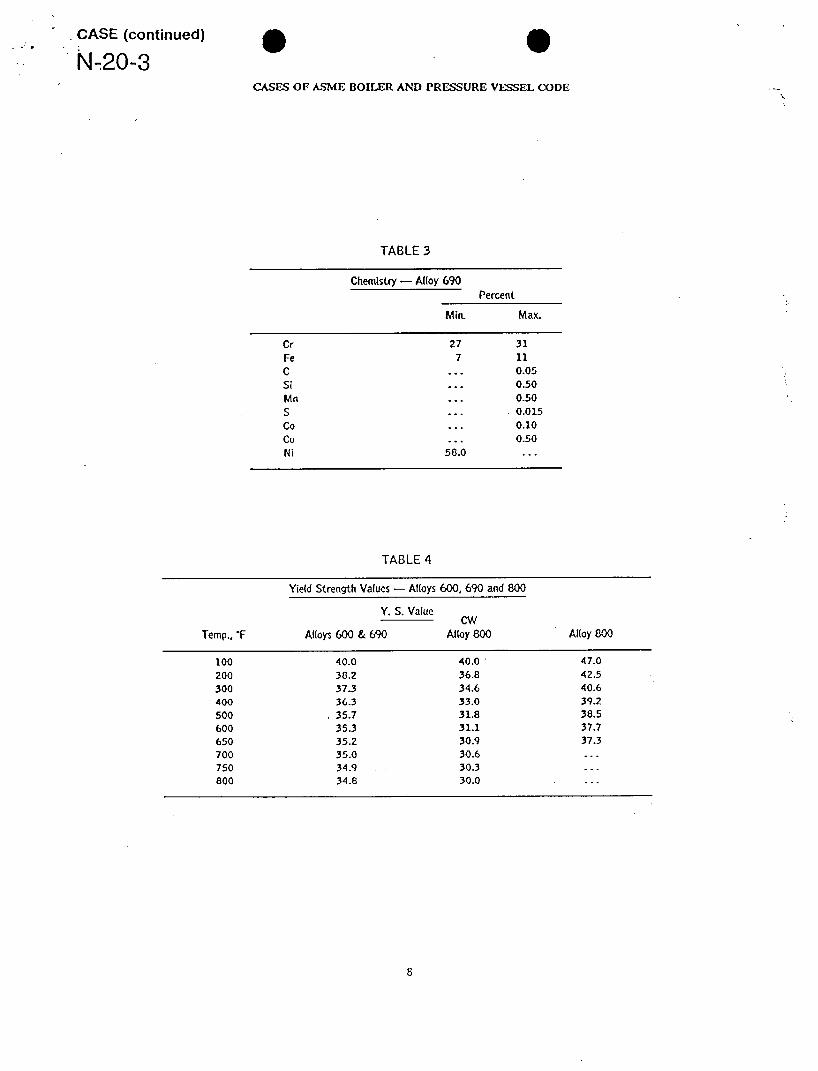
2. ASME Boiler and Pressure Vessel Code Case N-20-3, approved November 30, 1988 (attached)
Gentlemen:
The purpose of this letter is to request approval in accordance with 10 CFR 50.55a(a)(3), to use the alternative rules of American Society of Mechanical Engineers Boiler and Pressure Vessel Code (ASME), Section III, Code Case N-20-4 (Reference 1), in lieu of the currently required heat exchanger tubing materials. The use of nickel-chromium-iron Alloy 690 heat exchanger tubing is necessary in the fabrication and installation of the Oconee Units 1, 2 and 3 replacement steam generators. This tubing material has been approved by ASME through Code Case N-20-4 and is designated as UNS N06690 (Alloy
690). Use of this tubing material in the fabrication of replacement steam generators has been previously approved by the
NRC through ASME Code Case N-20-3 (Reference 2). Code Case N-20-3 is currently listed as an acceptable code case in Regulatory Guide 1.85, Rev 31 (May 1999), "Materials Code Case Acceptability ASME Sectio II, Division 1."
9909280405 990923 A-CA PDR ADOCK 05000269 P PDR
* 0
USNRC Document Control Desk Page 2 September 23, 1999
The code case revision corrected values for the yield strength and ultimate.strength of Alloy 690. At the time of issue of N-20-3, industry experience was primarily limited to Inconel 600. Because of the similarity of the materials it was assumed that properties would be similar. With growth of industry experience with Alloy 690 it was determined that a consistent difference exists in material properties between Inconel 600 and Alloy 690. Alloy 690 has a yield strength approximately 10% lower than Inconel 600 and an ultimate strength less than 10% lower. N-20-4 was subsequently issued to accurately reflect these Alloy 690 material properties. Use of Code Case N-20-4 is considered conservative since relevant design analyses will be performed using accurate rather than the incorrect high values for material strength.
The procurement and fabrication schedule for the Oconee replacement steam generators requires that decisions concerning heat exchanger tubes need to be made in the near future. Duke Energy Corporation requests approval for the use of Code Case N-20-4 by December 1, 1999.
If there are any questions, please contact Robert Sharpe at (704) 382-0956.
Very truly yours,
W. R. McCollum, Jr. Site Vice Preside~
Attachments
* 0
USNRC Document Control Desk Page 3
September 23, 1999
Xc: L. A. Reyes
Regional Administrator, Region II U. S. Nuclear Regulatory Commission Atlanta Federal Center 61 Forsyth Street, SW, Suite 23T85 Atlanta, GA 30303
D. E. Billings Acting Senior Resident Inspector Oconee Nuclear Station
D. E. LaBarge Senior Project Manager Office of Nuclear Reactor Regulation U. S. Nuclear Regulatory Commission
V. R. Autry Director, Division of Radioactive Waste Management Bureau of Land & Waste Management S. C. Department of Health and Environmental Control 2600 Bull Street Columbia, SC 29201
* 0 ATTcl-1 m ^ a CASE
N-20-4 CASES OF ASME BOILER AND PRESSURE VESSEL CODE,
Approval Date: February 26, 1999
See Numeric Index for expiration and any reaffirmation dates.
Case N-20-4 1, providing the following additional requirements SB-163, Cold Worked UNS N08800; and SB-163 are met. UNS N06600, UNS N06690, and UNS N08800 to (a) The design stress intensity values shall be those Supplementary Requirements S2 of SB-163 listed in Table 1. Section III, Division 1, Class 1 (b) The yield strength values shall be that listed in
Table 2. Inquiry: May SB-163 Cold Worked UNS N08800; (c) The tensile strength values shall be that listed
and SB-163 UNS N06600, UNS N06690, and UNS in Table 3. N08800 meeting the requirements of Supplementary (d) For external pressure, the required thickness of Requirement S2 of SB-163, be used in the construc- the tubing shall be determined in accordance with par. tion of Class I components in accordance with Section NB-3133, using Fig. 1 for alloys UNS N06600 and m, Division I? UNS N06690 and Fig. 2 for alloy UNS N08800.
(e) Welding procedure and performance qualificaReply: It is the opinion of the Committee that SB- tions shall be in accordance with Section IX. Welding
163 Cold Worked UNS N08800; and SB-163 UNS of cold-worked alloy UNS N08800 shall be limited to N06600, UNS N06690, and UNS N08800 meeting the tube-to-tube sheet welds. requirements of Supplementary Requirement S2 of (f) This Case number shall be shown in the documenSB-163, may be used in the construction of Class I tation and marking of the material and in the Certificate components in accordance with Section s s, Division Holders Data Report.
NOTE: (1) Due to the relatively low yield strength of these materials, these higher stress values were established at temperatures where the short time
tensile properties govern to permit the use of these alloys where slightly greater deformation is acceptable. The stress values in this range exceed 662/3% but do not exceed 90% of the yield strength at temperature. Use of these stresses may result in dimensional changes due to permanent strain. These stress values are not recommended for the flanges of gasketed joints or other applications where slight amounts of distortion can cause leakage or malfunction. Table Y-2 of Section 11, Part D, lists multiplying factors that, when applied to the yield strength values shown in Table 2, will give allowable stress values that will result in lower levels of permanent strain.
7 SUPP. 4-NC
CASE (continued)
N-20-4 CASES OF ASME BOILER AND PRESSURE VESSEL CODE
TABLE 2 YIELD STRENGTH VALUES [Note (1)]
For Material Temperature
Not Exceeding OF UNS N06600 UNS N06690 UNS N08800 CW UNS NO8800
FIG. 3 CHART FOR DETERMINING SHELL THICKNESS OF CYLINDRICAL AND SPHERICAL VESSELS UNDER EXTERNAL PRESSURE WHEN CONSTRUCTED OF SB-163 COLD WORKED UNS N08800
10.1 SUPP. 4 - NC
* * * AflkAc K - $CASE N-20-3
CASES OF ASME BOILER AND PRESSURE VESSEL CODE
Approval Date: November 30, 1988
See Numeric Index for expiration and any reaffirmation dates.
Case N-20-3 chromium Alloy 800 seamless condenser and heat exSB-163 Nickel-Chromium-Iron Tubing (Alloys 600 changer tubing meeting the requirements given on the and 690) and Nickel-Iron-Chromium Alloy 800 at a inquiry may be used in the construction of Class I
Specified Minimum Yield Strength of 40.0 ksi and components in accordance with Section 111, Division Cold Worked Alloy 800 at a Yield Strength of 1, provided the tensile, yield strength, and design stress
47.0 ksi intensity values as listed in Tables 1, 2, and 4, respecSection III, Division 1, Class 1 tively are used. In addition to the marking require
ments of SB-163, the tubing shall be identified with Inquiry: May nickel-chromium-iron and nickel- this Case number. For external pressure the required
iron-chromium alloy seamless condenser and heat ex- thickness of the tubing shall be determined in accor
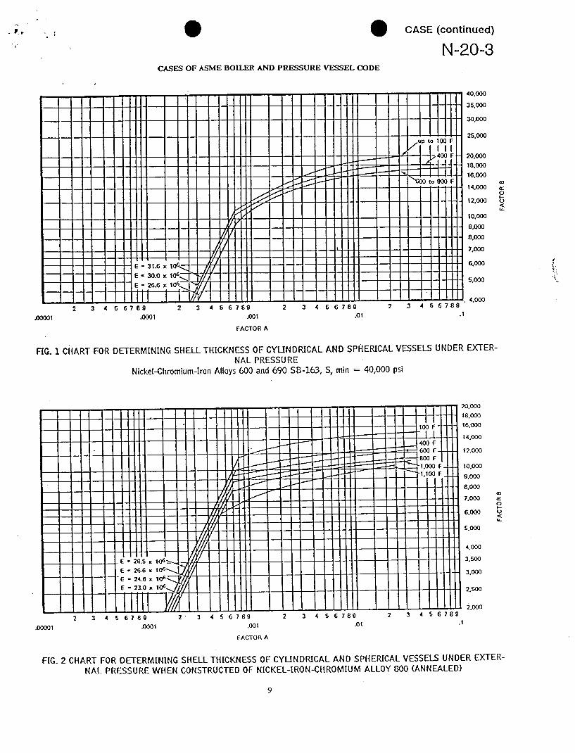
changer tubing meeting the size range and specified dance with Par. NB-3133 using Fig. I for Alloys 600 properties as listed in Table I and otherwise meeting and 690 and using Fig. 2 for Alloy 800. Welding pro
the requirements of SB-163 for Alloy 600 and 800 and cedure and performance qualifications shall be in
the requirements of SB-163 for Alloy 690 except for accordance with Section IX. Separate welding procethe chemistry (Alloy 690 chemistry is listed in Table dure and performance qualifications are required for
3), be used in the construction of Class I components Alloy 690. Welding of CW Alloy 800 material shall in accordance with Section III, Division n? be limited to tube-to-tube sheet welds.
Reply: It is the opinion of the Committee that nickel-chromium-iron Alloys 600 and 690 and nickel-iron
TABLE 1
Specified Mechanical Properties and Size Ranges
M. Spec Spec. Yield Strength Min. Tube Size Range, In.
Tensile t (0.2% Offset) Elongation Wall
Strengthm ksi MS3. Max. 2 In., % i.d. Thickness
Alloys 600 and 690 80 40 65 30 to Up to 0.100
Alloy 800 80 40 65 30 Y/, to /, Up to 0.100
CW Alloy 800 83 47 70 30 an to usUp to 0.100
TABLE 2
Design Stress Intensity Values, S w ksi, for MaterianTemerature Not Exceeding, p