Scientific and technological advances from DCNS_no. 2 RE SEARCH ENERGY OPTIMISATION PRODUCTIVITY AND COMPETITIVENESS OF INDUSTRIAL PROCESSES PERFORMANCE AT SEA AND MARINE PLATFORM DYNAMICS STEALTH AND ANTENNA INTEGRATION INFORMATION MANAGEMENT THROUGH LIFE RESISTANCE ONBOARD INTELLIGENCE
Transcript
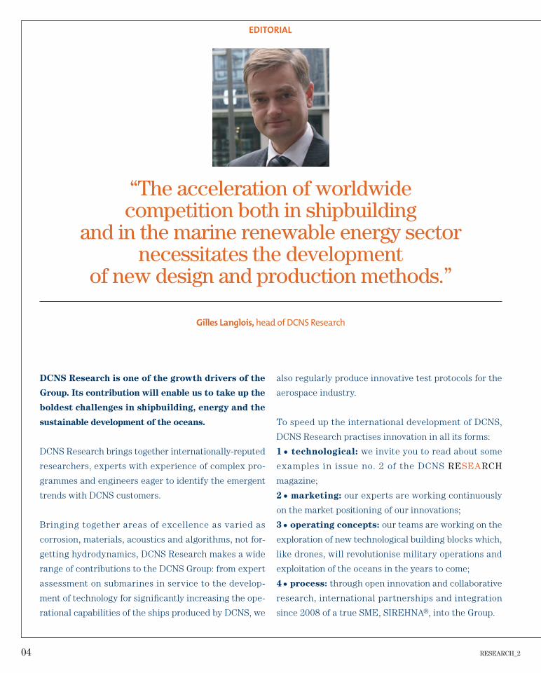
Scientific and technological advances from DCNS_no. 2
RESEARCHE
NE
RG
Y O
PT
IMIS
AT
ION
PR
OD
UC
TIV
ITY
AN
D C
OM
PE
TIT
IVE
NE
SS
OF I
ND
UST
RIA
L P
RO
CE
SS
ES
PE
RFO
RM
AN
CE
AT
SE
A
AN
D M
AR
INE
PLA
TFO
RM
DY
NA
MIC
S
STEA
LTH
AN
D A
NTEN
NA
INTEG
RA
TIO
N
INFO
RM
ATIO
N M
AN
AG
EM
EN
T
TH
RO
UG
H L
IFE R
ES
ISTA
NC
E
ON
BO
AR
D IN
TELLIG
EN
CE
RESEARCH_2 03
CONTENTS
04_ EDITORIAL
06_ FOREWORD
08_ NEWS
11_ PERFORMANCE AT SEA AND MARINE PLATFORM DYNAMICS
Virtual Ship: integrated ship design in the preliminary project phase MAX: generic autonomous modelfor submarine manoeuvrability studies
17_ THROUGH LIFE RESISTANCModelling of mechanical propulsion transmissionsComposite material antenna systemsMultifunctional composite materials for military naval applications
25_ ENERGY OPTIMISATIONOptimised operation of ships: simulations and optimisations
29_ ONBOARD INTELLIGENCEArchitecture of a guidance system for autonomous vehicles
33_INFORMATION MANAGEMENTNew data association processing solutions Tracking manoeuvring targets in 3DInnovation and human factors
43_STEALTH AND ANTENNA INTEGRATIONVibroacoustic radiation by plates in transient states
47_ PRODUCTIVITY AND COMPETITIVENESSOF INDUSTRIAL PROCESSES
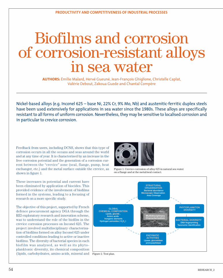
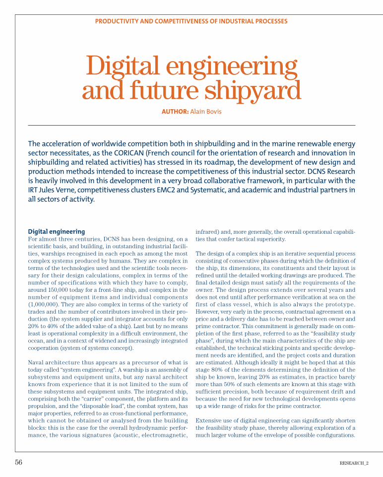
Evaluation of friction stir welding (FSW) on high yield strength steels for shipbuildingThe development of TOFD at DCNSBiofi lms and corrosion of corrosion-resistant alloys in sea waterDigital engineering and future shipyard
60_OUR SCIENTIFIC PUBLICATIONS
RESEARCH_2. The DCNS scientifi c and technological review. Executive editor: Gilles LANGLOIS _Editorial board: Christian AUDOLY, Julien BÉNABÈS, Alexia BONNIFET, Luc BORDIER, Marc BOUSSEAU, Jean-Michel CORRIEU, François CORTIAL, Xavier DAL SANTO, Sylvain FAURE (CEA), Fabien GAUGAIN, Anne-Marie GROLLEAU, Joëlle GUTIERREZ, Emmanuel HERMS (CEA), Guillaume JACQUENOT, Dann LANEUVILLE, Cédric LEBLOND, Jean-Jacques MAISONNEUVE, Thierry MILLOT, Pol MULLER, Adrien NEGRE, Antoine PAGÈS, Fabian PÉCOT, Mathieu PRISER, Ygaal RENOU, Lucie ROULEAU, Céline ROUSSET, David ROUXEL, Florent SAINCLAIR, David-François SAINT-CYR, Jean-François SIGRIST, Camille YVIN _Design and production: _Photo credits: DCNS – all rights reserved.
and other higher education institutions must collaborate
to invent, innovate and develop new concepts, new pro-
ducts and new services. Collaborative research and open
innovation amplify the fl ourishing of ideas and speed up
the emergence of new technologies.
But there are also considerable human issues. One of
these issues is in education and training. Our world is
changing every day, our time is fi lled with uncertainties
and, little by little, some citizens are fi nding themselves
on the margins of this society of knowledge. We must
also prepare our young people to master, and tomorrow
invent, this ever-changing technology. How can not only
sound knowledge but also the thirst for understanding,
the appetite for learning and the enthusiasm for creating
be transmitted to as many as possible?
It is now necessary to invent, in society as in compa-
nies, new forms of communication, more interactive,
more participative and more creative, restore pas-
sion to the professions of industry, give new life to the
technical sector.
I salute the DCNS initiative to publish the latest results
of its technological research. Much of this work is being
done by brilliant doctoral students. I hope that they
contribute to mobilising yet more young people for the
fi ne professions of the sea.
The Océanides project
Claudie Haigneré, President of Universcience
RESEARCH_2 07
FOREWORD
08 RESEARCH_2
NEWS
At the end of November 2013, Patrick Boissier announced the signature of a partnership with Dalhousie University in Halifax for developing bilateral research programmes.
The MoU (Memorandum of Understanding) defines the general framework for collaboration programmes for five years. According to Jean-François Sigrist, manager of the research team at DCNS Research, this MoU represents a non-negligible competitive advantage for DCNS: “We are going to develop new research work with Dalhousie University on the ‘dynamics of structures’ (surface ships, submarines, offshore platforms, etc.) and their behaviour in the marine environment. We are also planning scientifi c exchanges between France and Canada, and hosting of students (master, doctorate).”These encouraging prospects for DCNS, in the position of challenger in the face of competition from the United States, echo the announcement by Prime Minister Harper and President Hollande in June of a roadmap for bilateral cooperation, covering for example international security and defence. They also contribute to a climate of strengthened economic partnership following the recent signature of a free trade agreement between Canada and Europe.
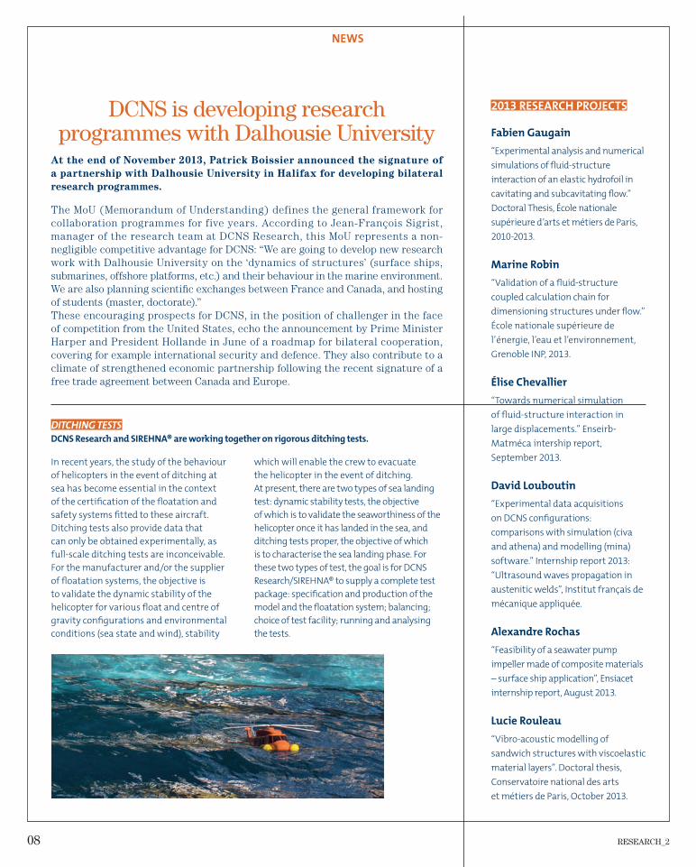
DITCHING TESTS
DCNS Research and SIREHNA® are working together on rigorous ditching tests.
DCNS is developing research programmes with Dalhousie University
In recent years, the study of the behaviour
of helicopters in the event of ditching at
sea has become essential in the context
of the certifi cation of the fl oatation and
safety systems fi tted to these aircraft.
Ditching tests also provide data that
can only be obtained experimentally, as
full-scale ditching tests are inconceivable.
For the manufacturer and/or the supplier
of fl oatation systems, the objective is
to validate the dynamic stability of the
helicopter for various fl oat and centre of
gravity confi gurations and environmental
conditions (sea state and wind), stability
which will enable the crew to evacuate
the helicopter in the event of ditching.
At present, there are two types of sea landing
test: dynamic stability tests, the objective
of which is to validate the seaworthiness of the
helicopter once it has landed in the sea, and
ditching tests proper, the objective of which
is to characterise the sea landing phase. For
these two types of test, the goal is for DCNS
Research/SIREHNA® to supply a complete test
package: specifi cation and production of the
model and the fl oatation system; balancing;
choice of test facility; running and analysing
the tests.
2013 RESEARCH PROJECTS
Fabien Gaugain
“Experimental analysis and numerical
simulations of fl uid-structure
interaction of an elastic hydrofoil in
cavitating and subcavitating fl ow.”
Doctoral Thesis, École nationale
supérieure d’arts et métiers de Paris,
2010-2013.
Marine Robin
“Validation of a fl uid-structure
coupled calculation chain for
dimensioning structures under fl ow.”
École nationale supérieure de
l’énergie, l’eau et l’environnement,
Grenoble INP, 2013.
Élise Chevallier
“Towards numerical simulation
of fl uid-structure interaction in
large displacements.” Enseirb-
Matméca intership report,
September 2013.
David Louboutin
“Experimental data acquisitions
on DCNS confi gurations:
comparisons with simulation (civa
and athena) and modelling (mina)
software.” Internship report 2013:
“Ultrasound waves propagation in
austenitic welds”, Institut français de
mécanique appliquée.
Alexandre Rochas
“Feasibility of a seawater pump
impeller made of composite materials
– surface ship application”, Ensiacet
internship report, August 2013.
Lucie Rouleau
“Vibro-acoustic modelling of
sandwich structures with viscoelastic
material layers”. Doctoral thesis,
Conservatoire national des arts
et métiers de Paris, October 2013.
RESEARCH_2 09
NEWS
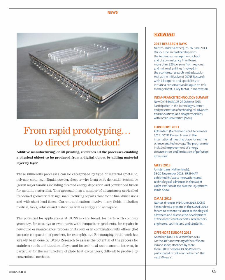
From rapid prototyping… to direct production!
Additive manufacturing, or 3D printing, combines all the processes enabling
a physical object to be produced from a digital object by adding material
layer by layer.
These numerous processes can be categorised by type of material (metallic,
polymer, ceramic, in liquid, powder, sheet or wire form) or by deposition technique
(seven major families including directed energy deposition and powder bed fusion
for metallic materials). This approach has a number of advantages: unrivalled
freedom of geometrical design, manufacturing of parts close to the final dimensions
and with short lead times. Current applications involve many fields, including
medical, tools, vehicles and fashion, as well as energy and aerospace.
The potential for applications at DCNS is very broad: for parts with complex
geometry, for coatings or even parts with composition gradients, for repairs in
new-build or maintenance, process on its own or in combination with others (hot
isostatic compaction of powders, for example), etc. Encouraging initial work has
already been done by DCNS Research to assess the potential of the process for
stainless steels and titanium alloys, and its technical and economic interest, in
particular for the manufacture of plate heat exchangers, difficult to produce by
conventional methods.
KEY EVENTS
2013 RESEARCH DAYS
Nantes-Indret (France), 25-26 June 2013.
On 25 June, in partnership with
the Audencia management school
and the consultancy fi rm Bessé,
more than 220 persons from regional
and national entities involved in
the economy, research and education
met at the initiative of DCNS Research
with 15 experts and specialists to
initiate a constructive dialogue on risk
management, a key factor in innovation.
INDIA-FRANCE TECHNOLOGY SUMMIT
New Delhi (India), 23-24 October 2013.
Participation in the Technology Summit
and presentation of technological advances
and innovations, and also partnerships
with Indian universities (MoU).
EUROPORT 2013
Rotterdam (Netherlands) 5-8 November
2013. DCNS Research was at the
international meeting place for marine
science and technology. The programme
included improvement of energy
consumption and limitation of pollution
emissions.
METS 2013
Amsterdam (Netherlands),
18-20 November 2013. SIREHNA®
exhibited its latest innovations and
technological advances in the Super
Yacht Pavilion at the Marine Equipment
Trade Show.
OMAE 2013
Nantes (France), 9-14 June 2013. DCNS
Research was present at the OMAE 2013
forum to present its latest technological
advances and discuss the development
of the oceans with experts, researchers,
engineers, technicians and students.
OFFSHORE EUROPE 2013
Aberdeen (UK), 3-6 September 2013.
For the 40th anniversary of the Off shore
Europe show, attended by more
than 63,000 persons, DCNS Research
participated in talks on the theme “The
next 50 years”.
10 RESEARCH_2
RESEARCH_2 11
PERFORMANCE AT SEA AND MARINE PLATFORM DYNAMICS
Hull drag computation, model tests in a hydrody-
namic basin, simulating the seakeeping character-
istics of a structure, optimising propulsion units,
design of dynamic stabilisation systems, analysing
the launch of underwater weapons: this sector
embraces all activities enhancing the effectiveness
and reliability of powered and unpowered marine
platforms in mission execution.
12 RESEARCH_2
PERFORMANCE AT SEA AND MARINE PLATFORM DYNAMICS
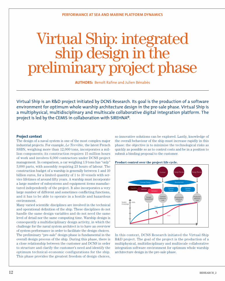
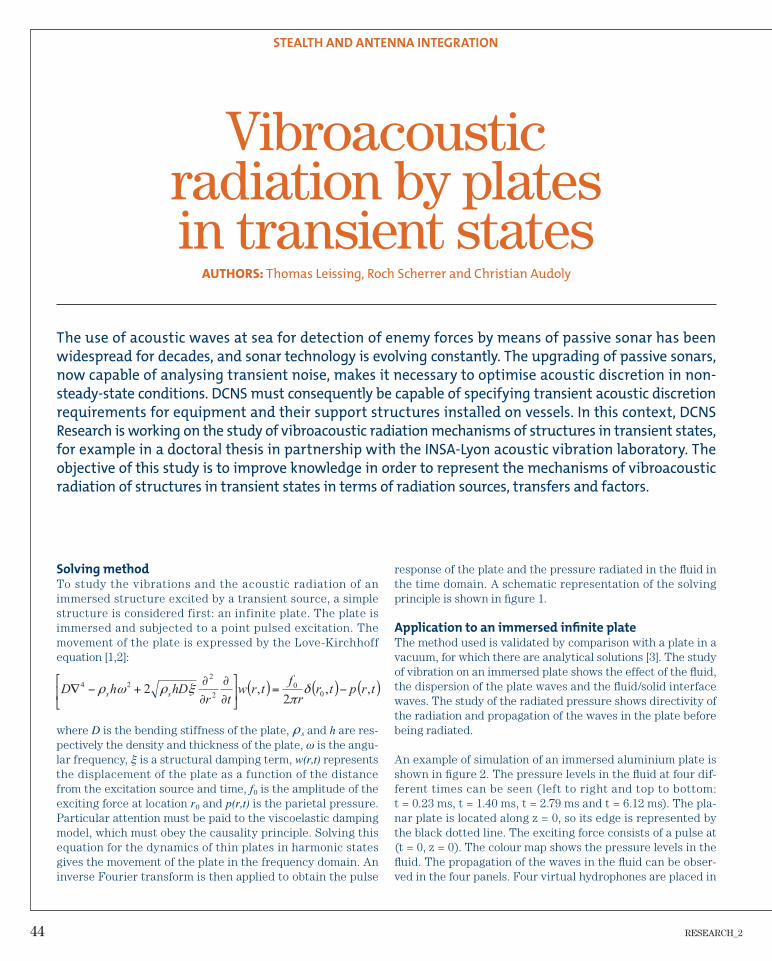
so innovative solutions can be explored. Lastly, knowledge of the overall behaviour of the ship must increase rapidly in this phase: the objective is to minimise the technological risks as quickly as possible so as to control costs and be in a position to submit a binding proposal to the customer.
Product control over the project life cycle.
100%System knowledge
Real
Ideal
Development reference
cost
Contract Design Review Design Review
Concept Design Development
FeasibilityDefinition
Validation
Contract Design
Detailed Design
Budget Assessment
Contractreference
cost
Production reference
cost
In this context, DCNS Research initiated the Virtual Ship R&D project. The goal of the project is the production of a multi physical, multidisciplinary and multiscale collaborative integration software environment for optimum whole warship architecture design in the pre-sale phase.
Virtual Ship: integrated ship design in the
preliminary project phase
Project context
The design of a naval system is one of the most complex major industrial projects. For example, Le Terrible, the latest French SSBN, weighing more than 12,000 tons, incorporates a mil-lion components; its construction requires 15 million hours of work and involves 6,000 contractors under DCNS project management. In comparison, a car weighing 1.9 tons has “only” 3,000 parts, with assembly requiring 23 hours of labour. The construction budget of a warship is generally between 1 and 10 billion euros, for a limited quantity of 1 to 10 vessels with ser-vice lifetimes of around fi fty years. A warship must incorporate a large number of subsystems and equipment items manufac-tured independently of the project. It also incorporates a very large number of different and sometimes confl icting functions, and it has to be able to operate in a hostile and hazardous environment.Many varied scientifi c disciplines are involved in the technical and operational defi nition of the ship. These disciplines do not handle the same design variables and do not need the same level of detail nor the same computing time. Warship design is consequently a multidisciplinary design activity, in which the challenge for the naval system architect is to have an overview of system performance in order to facilitate the design choices.The preliminary “pre-sale” design phase is fundamental in the overall design process of the ship. During this phase, there is a close relationship between the customer and DCNS in order to structure and clarify the customer’s need and identify the optimum technical-economic configurations for the ship. This phase provides the greatest freedom of design choices,
AUTHORS: Benoît Rafi ne and Julien Bénabès
Virtual Ship is an R&D project initiated by DCNS Research. Its goal is the production of a software
environment for optimum whole warship architecture design in the pre-sale phase. Virtual Ship is
a multiphysical, multidisciplinary and multiscale collaborative digital integration platform. The
project is led by the CEMIS in collaboration with SIREHNA®.
RESEARCH_2 13
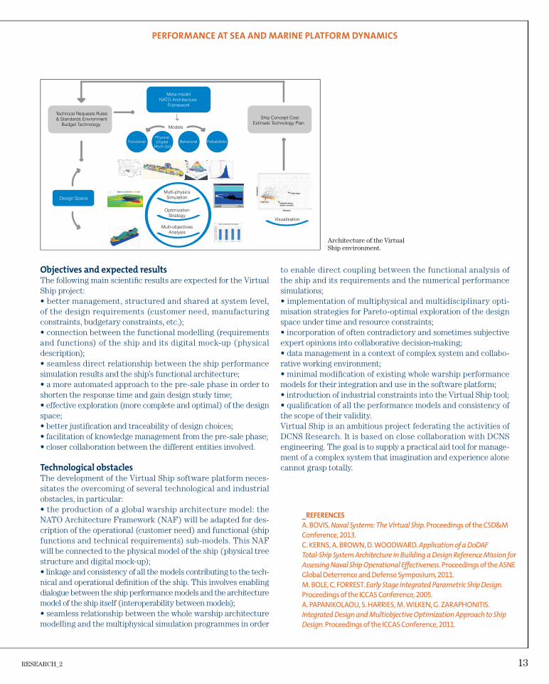
Objectives and expected results
The following main scientifi c results are expected for the Virtual Ship project:• better management, structured and shared at system level, of the design requirements (customer need, manufacturing constraints, budgetary constraints, etc.);• connection between the functional modelling (requirements and functions) of the ship and its digital mock-up (physical description);• seamless direct relationship between the ship performance simulation results and the ship’s functional architecture;• a more automated approach to the pre-sale phase in order to shorten the response time and gain design study time;• effective exploration (more complete and optimal) of the design space;• better justifi cation and traceability of design choices;• facilitation of knowledge management from the pre-sale phase;• closer collaboration between the different entities involved.
Technological obstacles
The development of the Virtual Ship software platform neces-sitates the overcoming of several technological and industrial obstacles, in particular:• the production of a global warship architecture model: the NATO Architecture Framework (NAF) will be adapted for des-cription of the operational (customer need) and functional (ship functions and technical requirements) sub-models. This NAF will be connected to the physical model of the ship (physical tree structure and digital mock-up);• linkage and consistency of all the models contributing to the tech-nical and operational defi nition of the ship. This involves enabling dialogue between the ship performance models and the architecture model of the ship itself (interoperability between models);• seamless relationship between the whole warship architecture modelling and the multiphysical simulation programmes in order
_REFERENCES
A. BOVIS. Naval Systems: The Virtual Ship. Proceedings of the CSD&M
Conference, 2013.
C. KERNS, A. BROWN, D. WOODWARD. Application of a DoDAF
Total-Ship System Architecture in Building a Design Reference Mission for
Assessing Naval Ship Operational Eff ectiveness. Proceedings of the ASNE
Global Deterrence and Defense Symposium, 2011.
M. BOLE, C. FORREST. Early Stage Integrated Parametric Ship Design.
Proceedings of the ICCAS Conference, 2005.
A. PAPANIKOLAOU, S. HARRIES, M. WILKEN, G. ZARAPHONITIS.
Integrated Design and Multiobjective Optimization Approach to Ship
Design. Proceedings of the ICCAS Conference, 2011.
Architecture of the Virtual Ship environment.
to enable direct coupling between the functional analysis of the ship and its requirements and the numerical performance simulations;• implementation of multiphysical and multidisciplinary opti-misation strategies for Pareto-optimal exploration of the design space under time and resource constraints;• incorporation of often contradictory and sometimes subjective expert opinions into collaborative decision-making;• data management in a context of complex system and collabo-rative working environment;• minimal modifi cation of existing whole warship performance models for their integration and use in the software platform;• introduction of industrial constraints into the Virtual Ship tool;• qualifi cation of all the performance models and consistency of the scope of their validity.Virtual Ship is an ambitious project federating the activities of DCNS Research. It is based on close collaboration with DCNS engineering. The goal is to supply a practical aid tool for manage-ment of a complex system that imagination and experience alone cannot grasp totally.
PERFORMANCE AT SEA AND MARINE PLATFORM DYNAMICS
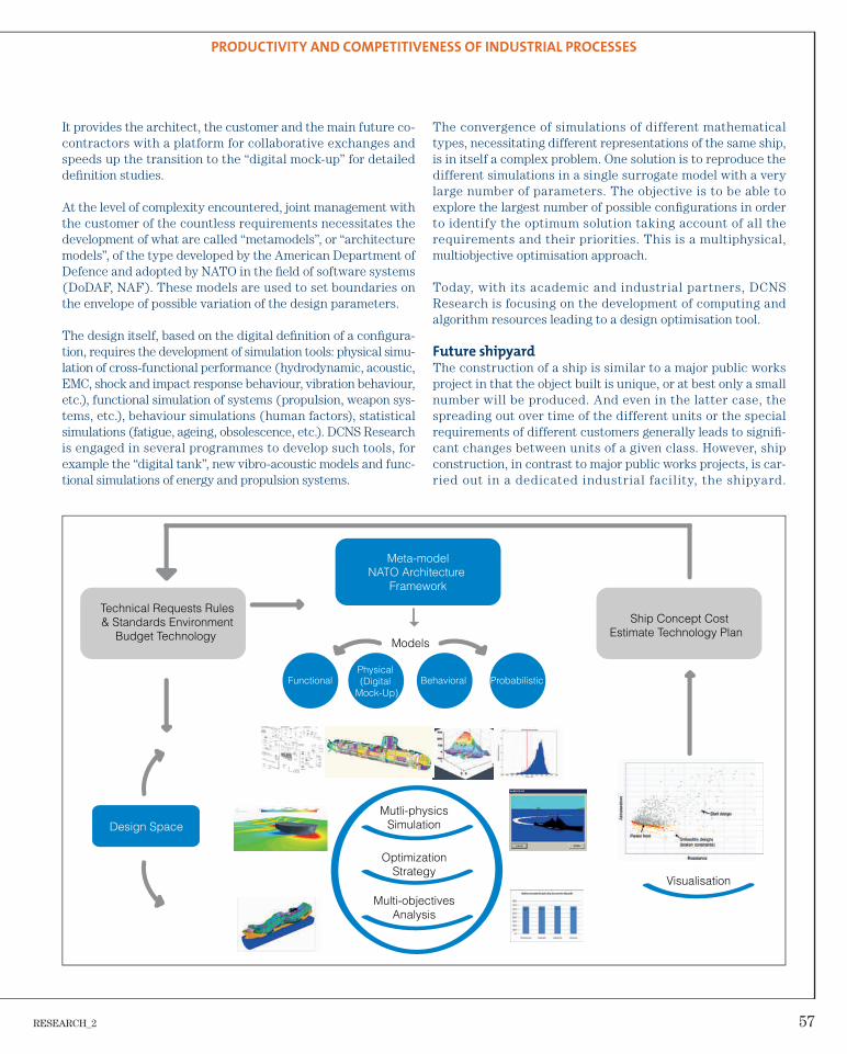
Models
Meta-modelNATO Architecture
Framework
Technical Requests Rules & Standards Environment
Budget Technology
Ship Concept Cost Estimate Technology Plan
FunctionalPhysical (Digital
Mock-Up)Behavioral Probabilistic
Design SpaceMutli-physics
Simulation
OptimizationStrategy
Multi-objectivesAnalysis
Visualisation
EHCLS*
NDMS
Decoy launcher
DECOY'SLAUNCHERS
EHCLS*
ASRU
14 RESEARCH_2
• defi ne the control laws;• conduct specifi c studies such as the effect of sea bed proxim-ity on vessel behaviour.2012 was spent designing the model, while 2013 saw model assembly and qualifi cation trials at sea.
General concept
The general concept adopted is that of a generic tool, i.e. easily adaptable to the shapes and the characteristics of the DCNS sub-marine range. The model has a generic core structure comprising a watertight aluminium body 4 metres long to which specifi c ele-ments (bridge fi n, external shapes, steering gear) of the subma-rine to be represented can be fitted. The assembled model is between 7 metres and 10 metres long, according to the subma-rine being modelled, with a diameter of about 80 cm and a mass of about 2 tons. Designed to operate at depths down to 70 metres, the working depth is between 15 metres and 40 metres.
MAX(1): generic autonomous model
for submarine manoeuvrability studies
MAX: a multifunction underwater drone
Design and manufacturing, started in December 2011, were contracted by SM A Eng ineer ing to DCNS Research /SIREHNA®, which is also responsible for operational imple-mentation of MAX when it is in use. Simple and rapid to put into operation, MAX is autonomous, autopilot-controlled underwater and on the surface, reprogrammable for rapid test-ing of different confi gurations and adaptable to the hydrody-namic scales representative of the whole range of DCNS submarines.
It can be used to:• dimension the steering gear;• perform manoeuvrability tests (DG, DT) for identifi cation of the mathematical model of the vessel;• study the impact of specific appendages (stringers, deck shelters, etc.);
AUTHOR: Jérémie Raymond
The hydrodynamic design of a submarine means that the skin shape has to be frozen very early in the
preliminary project phase. Digital methods are employed to test different hydrodynamic configurations
for a vessel project. They are used in the preliminary project phase to compare designs and rank their
performance. Nevertheless, the hydrodynamic design of a submarine remains an empirical science. It is
consequently not possible to rely completely on the digital approach. Once a design has unanimous
acceptance, it must be characterised in the “real” world, by testing. This is the stage at which the new
model MAX becomes involved. It can obtain this “real world” characterisation very rapidly. In addition,
several steering gear variants can be compared. MAX enables the analysis of complex manoeuvres that
cannot as yet be modelled by numerical simulations. It can also be used to validate computer codes and
is positioned as a development in parallel to and complementing the “digital tank”.
PERFORMANCE AT SEA AND MARINE PLATFORM DYNAMICS
RESEARCH_2 15
Onboard systems
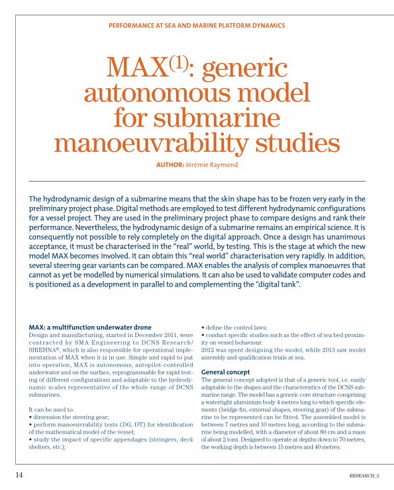
MAX has six independent actuators for rudder and plane con-trol. Propulsion is handled by a 2 kW motor and the propulsion unit is adaptable to each new project. Control and safety device management functions are performed by two instru-mentation and control computers. Test data is acquired by a dedicated acquisition unit. An IMU90 inertial measurement unit and an electromagnetic log give the speed and attitude of the submarine at any time. The weight regulating system is automatic, using a closed ballast. An acoustic communication device is used to determine the approximate position of the model when diving and tracking it during its movements. A Wi-Fi communication system is used for control on the sur-face and test data retrieval as soon as the model surfaces and for planning the next mission.
Tests and initial conclusions
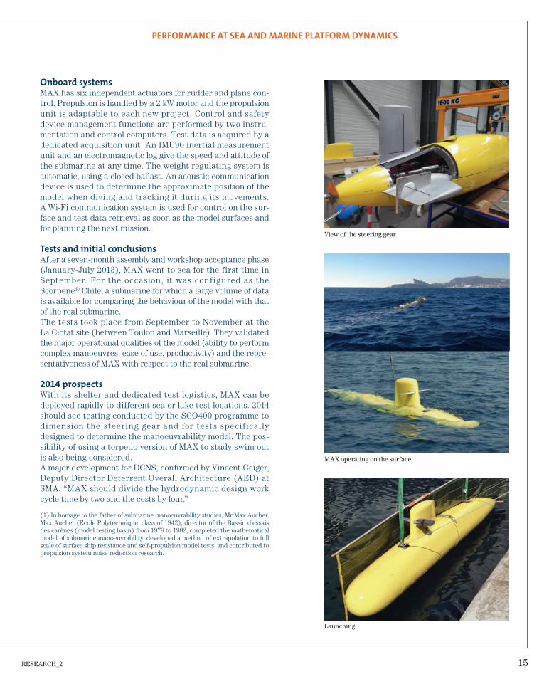
After a seven-month assembly and workshop acceptance phase (January-July 2013), MAX went to sea for the first time in September. For the occasion, it was configured as the Scorpene® Chile, a submarine for which a large volume of data is available for comparing the behaviour of the model with that of the real submarine.The tests took place from September to November at the La Ciotat site (between Toulon and Marseille). They validated the major operational qualities of the model (ability to perform complex manoeuvres, ease of use, productivity) and the repre-sentativeness of MAX with respect to the real submarine.
2014 prospects
With its shelter and dedicated test logistics, MAX can be deployed rapidly to different sea or lake test locations. 2014 should see testing conducted by the SCO400 programme to dimension the steering gear and for tests speci f ical ly designed to determine the manoeuvrability model. The pos-sibility of using a torpedo version of MAX to study swim out is also being considered.A major development for DCNS, confi rmed by Vincent Geiger, Deputy Director Deterrent Overall Architecture (AED) at SMA: “MAX should divide the hydrodynamic design work cycle time by two and the costs by four.”
(1) In homage to the father of submarine manoeuvrability studies, Mr Max Aucher. Max Aucher (Ecole Polytechnique, class of 1942), director of the Bassin d’essais des carènes (model testing basin) from 1979 to 1982, completed the mathematical model of submarine manoeuvrability, developed a method of extrapolation to full scale of surface ship resistance and self-propulsion model tests, and contributed to propulsion system noise reduction research.
View of the steering gear.
MAX operating on the surface.
Launching.
PERFORMANCE AT SEA AND MARINE PLATFORM DYNAMICS
16 RESEARCH_2
RESEARCH_2 17
THROUGH LIFE RESISTANCE
Throughout their working life, structures, whether
metallic or not, undergo natural or accidental
attack: corrosion, water impact, fire, shocks. Day
after day, they also face the phenomena of fatigue
and ageing. These attacks and other phenomena
call for calculations and testing to assess the dura-
bility of structures, as well as identify and try out
technological solutions to improve it.
18 RESEARCH_2
THROUGH LIFE RESISTANCE
without links between them, necessitating a large number of manual iterations and providing a relatively simplifi ed descrip-tion of the physics of the problems. The increasingly demanding discretion or cost constraints and the complexity of current sys-tems make it necessary to develop new tools at the junction of several fi elds of physics. These tools are being developed by the DCNS Research engineers using an approach that can be sum-marised in a few main stages:• problem analysis/literature survey;• defi nition of equations;
Modelling of mechanical propulsion
transmissions
Power transmission
Power transmission is a concern with very major issues invol-ving a number of complex components and consequently a num-ber of physical processes: shaft lines, housings, gearing, bearings, coupling components, etc.Overall shaft line and housing vibration processes giving rise to acoustic discretion problems are combined with very localised processes. The latter mainly concern tooth contacts and bearings, and necessitate particular attention in both the design and the manufacturing phases.
Development
of dedicated tools
For a long time, DCNS has been using high-performance tools based on a high level of empiri-cism and on the experience of its technicians and engineers.
More recently, with the deve-lopment of numerical tools, the engineering and design depart-ments have had access to tools with high performance but
AUTHOR: Romain Fargère
Power transmission is a major concern on a ship and affects the whole of the transmission system, from
the reduction gearbox to the propulsion propeller. Many factors are involved, including reliability, acous-
tic discretion and production cost. For an effective response to each of the issues, DCNS Research has
been working for several years on the development of dedicated numerical tools specifically designed to
take account of coupling between the various components and the physical processes. Used for a long
time in research applications, these tools are being rolled out in the engineering departments concerned.
They provide new perspectives, both in terms of working methods, favouring numerical/experimental
correlations, and in terms of design choices for the various components on future ships.
Schematic diagram of the transmission system of a ship.
Propeller (low speed)
Gearbox casing
Excited shaftline
Fluid bearings
Propeller (low speed)
Gearbox teeth in contact: excitation
RESEARCH_2 19
• digitisation/discretisation;• development of the solving method;• development of the communication interfaces (HMI).
An example of transfer:
reduction gearing simulation software
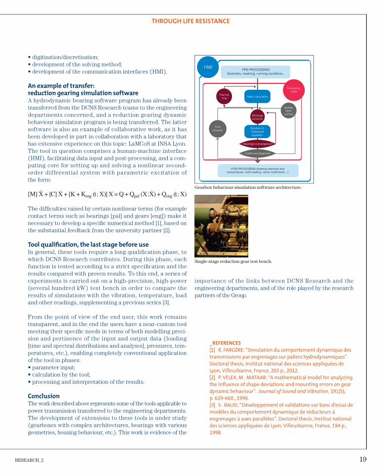
A hydrodynamic bearing software program has already been transferred from the DCNS Research teams to the engineering departments concerned, and a reduction gearing dynamic behaviour simulation program is being transferred. The latter software is also an example of collaborative work, as it has been developed in part in collaboration with a laboratory that has extensive experience on this topic: LaMCoS at INSA Lyon.The tool in question comprises a human-machine interface (HMI), facilitating data input and post-processing, and a com-puting core for setting up and solving a nonlinear second-order differential system with parametric excitation of the form:
The diffi culties raised by certain nonlinear terms (for example contact terms such as bearings [pal] and gears [eng]) make it necessary to develop a specifi c numerical method [1], based on the substantial feedback from the university partner [2].
Tool qualifi cation, the last stage before use
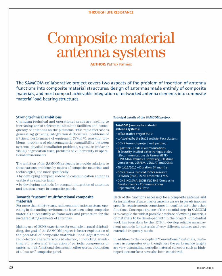
In general, these tools require a long qualifi cation phase, to which DCNS Research contributes. During this phase, each function is tested according to a strict specifi cation and the results compared with proven results. To this end, a series of experiments is carried out on a high-precision, high-power (several hundred kW) test bench in order to compare the results of simulations with the vibration, temperature, load and other readings, supplementing a previous series [3].
From the point of view of the end user, this work remains transparent, and in the end the users have a near-custom tool meeting their specifi c needs in terms of both modelling preci-sion and pertinence of the input and output data (loading [time and spectral distributions and analyses], pressures, tem-peratures, etc.), enabling completely conventional application of the tool in phases:• parameter input;• calculation by the tool;• processing and interpretation of the results.
Conclusion
The work described above represents some of the tools applicable to power transmission transferred to the engineering departments. The development of extensions to these tools is under study (gearboxes with complex architectures, bearings with various geometries, housing behaviour, etc.). This work is evidence of the
THROUGH LIFE RESISTANCE
_REFERENCES
[1] R. FARGÈRE: “Simulation du comportement dynamique des
transmissions par engrenages sur paliers hydrodynamiques”.
Doctoral thesis, Institut national des sciences appliquées de
Lyon, Villeurbanne, France, 203 p., 2012.
[2] P. VELEX, M . MATAAR: “A mathematical model for analyzing
the infl uence of shape deviations and mounting errors on gear
dynamic behaviour”. Journal of Sound and Vibration, 191(5),
p. 629-660., 1996.
[3] S . BAUD; “Développement et validations sur banc d’essai de
modèles du comportement dynamique de réducteurs à
engrenages à axes parallèles”. Doctoral thesis, Institut national
des sciences appliquées de Lyon, Villeurbanne, France, 194 p.,
1998.
importance of the links between DCNS Research and the engineering departments, and of the role played by the research partners of the Group.
POSt-PROCESSING (bearing reactions andtemperatures, tooth loading, varios coefficients…)
HMI
Computing code
Thermal loop
Update teeth
contactBearingssolutions
Solution of linéarizedequation
Timeincrease
20 RESEARCH_2
THROUGH LIFE RESISTANCE
Principal details of the SAMCOM project.
SAMCOM (composite material
antenna systems):
• collaborative project FUI 9;
• co-labelled by the EMC2 and Mer Paca clusters;
• DCNS Research project lead partner;
• 6 partners: Thales Communications
& Security, Institut d’électronique et des
télécommunications de Rennes (IETR-
UMR-6164, Rennes-1 university), Plastima
Composites, CERPEM, CEMCAT and DCNS;
• T0: 1/12/2010 – Duration: 54 months;
• DCNS teams involved: DCNS Research
CESMAN (lead), DCNS Research CEMIS;
• DCNS ING SMA, DCNS ING SNS (Composite
Developments – Communications
Department), SER Brest.
Each of the functions necessary for a composite antenna and for installation of antennas or antenna arrays in panels imposes specific requirements sometimes in conflict with the other functions. Consequently, one of the essential steps in SAMCOM is to compile the widest possible database of existing materials or materials to be developed within the project. Substantial work has been done by the IETR to develop reliable measure-ment methods for materials of very different natures and over extended frequency bands.
In addition to the concepts of “conventional” materials, custo-mary in composites even though here the performance targets are very demanding, periodic material concepts such as high-impedance surfaces have also been considered.
Composite material antenna systems
Strong technical ambitions
Changing technical and operational needs are leading to increasing use of telecommunications facilities and conse-quently of antennas on the platforms. This rapid increase is generating growing integration difficulties: problems of intrinsic performance of equipment (SWR(1)), masking pro-blems, problems of electromagnetic compatibility between systems, physical installation problems, signature (radar or visual) degradation risks, problems of vulnerability in opera-tional environments.
The ambition of the SAMCOM project is to provide solutions to these various problems by means of composite materials and technologies, and more specifi cally:• by developing compact wideband communication antennas usable at sea and on land;• by developing methods for compact integration of antennas and antenna arrays in composite panels.
Towards “custom” multifunctional composite
materials
For more than thirty years, radiocommunication systems ope-rating in demanding environments have been using composite materials successfully as framework and protection for the metal radiating elements of antennas.
Making use of DCNS experience, for example in naval shipbuil-ding, the goal of the SAMCOM project is better exploitation of the potential of composite materials: local adjustment of radioelectric characteristics (dielectric, conducting, insula-ting, etc. materials), integration of periodic components or patterns, multifunctional elements; in other words, production of a “custom” composite panel.
AUTHOR: Patrick Parneix
The SAMCOM collaborative project covers two aspects of the problem of insertion of antenna
functions into composite material structures: design of antennas made entirely of composite
materials, and most compact achievable integration of networked antenna elements into composite
material load-bearing structures.
RESEARCH_2 21
THROUGH LIFE RESISTANCE
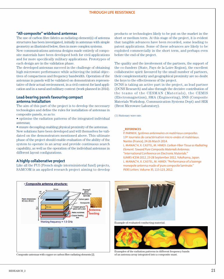
“All-composite” wideband antennas
The use of carbon fi bre fabrics as radiating element(s) of antenna structures has been investigated, initially in antennas with simple geometry as illustrated below, then in more complex systems.New communications antenna designs made entirely of compo-site materials have been developed both for civil applications and for more specifi cally military applications. Prototypes of each design are in the validation phase.The developed antennas succeed in the challenge of obtaining high microwave performance while achieving the initial objec-tives of compactness and frequency bandwidth. Operation of the antennas in panels will be validated on demonstrators represen-tative of their actual environment, in a civil context for land appli-cation and in a naval and military context (work planned in 2014).
Load-bearing panels favouring compact
antenna installation
The aim of this part of the project is to develop the necessary technologies and defi ne the rules for installation of antennas in composite panels, so as to:• optimise the radiation patterns of the integrated individual antennas;• ensure decoupling enabling physical proximity of the antennas.New solutions have been developed and will themselves be vali-dated on the demonstrators mentioned above. This ultimate phase of the project should enable evaluation of the ability of the system to operate in an array and provide continuous search capability, as well as the operation of the individual antennas in different layout confi gurations.
A highly collaborative project
Like all the FUI (French single interministerial fund) projects, SAMCOM is an applied research project aiming to develop
_REFERENCES
P. PARNEIX. Systèmes antennaires en matériaux composites.
13es Journées de caractérisation micro-ondes et matériaux.
Nantes (France), 24-26 March 2014.
L. MANAC’H, X. CASTEL, M. HIMDI. Carbon-Fiber Tissue as Radiating
Element: Toward Pure Composite Materials Antennas.
“International Conference on Electronic Materials.”
IUMRS-ICEM 2012, 23-28 September 2012, Yokohama, Japan.
L. MANAC’H, X. CASTEL, M. HIMDI. “Performance of a lozenge
monopole antenna made of pure composite laminate.”
PIERS Letters. Volume 35, 115-123, 2012.
products or technologies likely to be put on the market in the short or medium term. At this stage of the project, it is evident that tangible advances have been recorded, some leading to patent applications. Some of these advances are likely to be exploited commercially in the short term, and perhaps even before the end of the project.
The quality and the involvement of the partners, the support of the co-funders (State, Pays de la Loire Region), the excellent collaborative spirit favoured by the small number of partners, their complementarity and geographical proximity are no doubt the keys to the effectiveness of the project.DCNS is taking an active part in the project, as lead partner (DCNS Research) and also through the decisive contribution of the tea m s of the CESM A N ( Mater i a l s), the CEM IS (Electromagnetism), SMA (Engineering), SNS (Composite Materials Workshop, Communication Systems Dept) and SER (Brest Microwave Laboratory).
(1) Stationary wave rate.
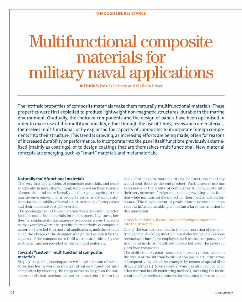
Example of evaluated conducting material.
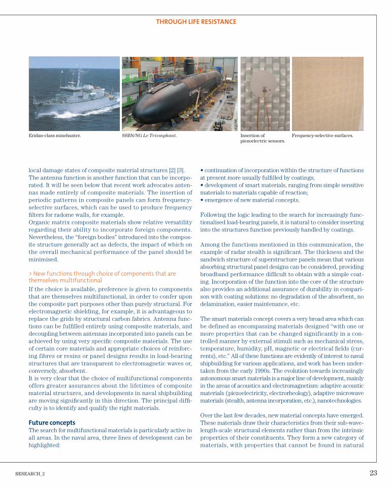
Examples of the radiation patterns in different frequency bands of an antenna array integrated into a composite mast.Composite antennas with copper or carbon fibre radiating elements [2].
22 RESEARCH_2
THROUGH LIFE RESISTANCE
basis of other performance criteria for functions that they would contribute to the end product. Furthermore, use has been made of the ability of composites to incorporate into their very structure foreign components providing a new func-tion while minimising the impact on their mechanical perfor-mance. The development of production processes such as vacuum infusion moulding is making a large contribution to this innovation.
> New functions by incorporation of foreign components
into the structure
One of the earliest examples is the incorporation of the elec-tromagnetic shielding function into dielectric panels. Various technologies have been employed, such as the incorporation of fine metal grids or metallised fabrics between the layers of glass fi bre composites.The ability to incorporate sensors and to carry information on the strain or the internal health of composite structures was subsequently exploited, for example by means of optical fi bre Bragg gratings [1]. More recently, work has also been done on other internal health monitoring methods, including the incor-poration of piezoelectric sensors for obtaining information on
Multifunctional composite materials for
military naval applications
Naturally multifunctional materials
The very fi rst applications of composite materials, and more specifi cally in naval shipbuilding, were based on their absence of corrosion and more broadly on their good ageing in the marine environment. This property remains a strong argu-ment for the durability of naval structures made of composites and their moderate cost of ownership.The non-magnetism of these materials was a determining factor for their use as hull materials for minehunters. Lightness, low thermal conductivity, transparency to acoustic waves: there are many examples where the specifi c characteristics of composite materials have led to structural applications, multifunctional since the choice of the designer was guided as much by the capacity of the composites to fulfi l a structural role as by the particular function provided by this family of materials.
Towards “custom” multifunctional composite
materials
Step by step, the preoccupation with optimisation of struc-tures has led to work on incorporating new functions into composites by choosing the components no longer on the sole criterion of their mechanical performance, but also on the
AUTHORS: Patrick Parneix and Mathieu Priser
The intrinsic properties of composite materials make them naturally multifunctional materials. These
properties were first exploited to produce lightweight non-magnetic structures, durable in the marine
environment. Gradually, the choice of components and the design of panels have been optimised in
order to make use of this multifunctionality, either through the use of fibres, resins and core materials,
themselves multifunctional, or by exploiting the capacity of composites to incorporate foreign compo-
nents into their structure. This trend is growing, as increasing efforts are being made, often for reasons
of increased durability or performance, to incorporate into the panel itself functions previously externa-
lised (mainly as coatings), or to design coatings that are themselves multifunctional. New material
concepts are emerging, such as “smart” materials and metamaterials.
RESEARCH_2 23
local damage states of composite material structures [2] [3].The antenna function is another function that can be incorpo-rated. It will be seen below that recent work advocates anten-nas made entirely of composite materials. The insertion of periodic patterns in composite panels can form frequency-selective surfaces, which can be used to produce frequency fi lters for radome walls, for example.Organic matrix composite materials show relative versatility regarding their ability to incorporate foreign components. Nevertheless, the “foreign bodies” introduced into the compos-ite structure generally act as defects, the impact of which on the overall mechanical performance of the panel should be minimised.
> New functions through choice of components that are
themselves multifunctional
If the choice is available, preference is given to components that are themselves multifunctional, in order to confer upon the composite part purposes other than purely structural. For electromagnetic shielding, for example, it is advantageous to replace the grids by structural carbon fabrics. Antenna func-tions can be fulfi lled entirely using composite materials, and decoupling between antennas incorporated into panels can be achieved by using very specifi c composite materials. The use of certain core materials and appropriate choices of reinforc-ing fibres or resins or panel designs results in load-bearing structures that are transparent to electromagnetic waves or, conversely, absorbent.It is very clear that the choice of multifunctional components offers greater assurances about the lifetimes of composite material structures, and developments in naval shipbuilding are moving signifi cantly in this direction. The principal diffi -culty is to identify and qualify the right materials.
Future concepts
The search for multifunctional materials is particularly active in all areas. In the naval area, three lines of development can be highlighted:
THROUGH LIFE RESISTANCE
• continuation of incorporation within the structure of functions at present more usually fulfi lled by coatings;• development of smart materials, ranging from simple sensitive materials to materials capable of reaction;• emergence of new material concepts.
Following the logic leading to the search for increasingly func-tionalised load-bearing panels, it is natural to consider inserting into the structures function previously handled by coatings.
Among the functions mentioned in this communication, the example of radar stealth is signifi cant. The thickness and the sandwich structure of superstructure panels mean that various absorbing structural panel designs can be considered, providing broadband performance diffi cult to obtain with a simple coat-ing. Incorporation of the function into the core of the structure also provides an additional assurance of durability in compari-son with coating solutions: no degradation of the absorbent, no delamination, easier maintenance, etc.
The smart materials concept covers a very broad area which can be defined as encompassing materials designed “with one or more properties that can be changed significantly in a con-trolled manner by external stimuli such as mechanical stress, temperature, humidity, pH, magnetic or electrical fi elds (cur-rents), etc.” All of these functions are evidently of interest to naval shipbuilding for various applications, and work has been under-taken from the early 1990s. The evolution towards increasingly autonomous smart materials is a major line of development, mainly in the areas of acoustics and electromagnetism: adaptive acoustic materials (piezoelectricity, electrorheology), adaptive microwave materials (stealth, antenna incorporation, etc.), nanotechnologies.
Over the last few decades, new material concepts have emerged. These materials draw their characteristics from their sub-wave-length-scale structural elements rather than from the intrinsic properties of their constituents. They form a new category of materials, with properties that cannot be found in natural
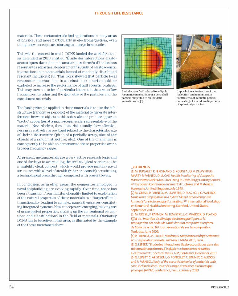
Eridan-class minehunter. SSBN/NG Le Triomphant. Insertion of piezoelectric sensors.
Frequency-selective surfaces.
24 RESEARCH_2
materials. These metamaterials fi nd applications in many areas of physics, and more particularly in electromagnetism, even though new concepts are starting to emerge in acoustics.
This was the context in which DCNS funded the work for a the-sis defended in 2013 entitled “Étude des interactions élasto-acoustiques dans des métamatériaux formés d’inclusions résonnantes réparties aléatoirement” (Study of elastoacoustic interactions in metamaterials formed of randomly-distributed resonant inclusions) [5]. This work showed that particle local resonance mechanisms in an elastomer matrix could be exploited to increase the performance of hull acoustic coatings. This may turn out to be of particular interest in the area of low frequencies, by adjusting the geometry of the particles and the constituent materials.
The basic principle applied in these materials is to use the sub-structure (random or periodic) of the material to generate inter-ferences between objects at this sub-scale and produce apparent “exotic” properties at a macroscopic scale, representative of the material. Nevertheless, these materials usually show effective-ness in a relatively narrow band related to the characteristic size of their substructure (pitch of a periodic array, size of the objects of a random structure, etc.). One of the challenges is consequently to be able to demonstrate these properties over a broader frequency range.
At present, metamaterials are a very active research topic and one of the keys to overcoming the technological barriers to the invisibility cloak concept, which would provide military naval structures with a level of stealth (radar or acoustic) constituting a technological breakthrough compared with present levels.
In conclusion, as in other areas, the composites employed in naval shipbuilding are evolving rapidly. Over time, there has been a transition from multifunctionality limited to exploitation of the natural properties of these materials to a “targeted” mul-tifunctionality, leading to complex panels themselves constitut-ing integrated systems. New concepts are emerging, making use of unsuspected properties, shaking up the conventional percep-tions and classifications in the field of materials. Obviously DCNS has to be active in this area, as illustrated by the example of the thesis mentioned above.
_REFERENCES
[1] M. BUGAULT, P. FERDINAND, S. ROUGEAUD, V. DEWYNTER-
MARTY, P. PARNEIX, D. LUCAS. Health Monitoring of Composite
Plastic Waterworks Lock Gates Using in-Fibre Bragg Grating Sensors.
4th European Conference on Smart Structures and Materials,
Harrogate, United Kingdom, July 1998.
[2] M. GRESIL, P. PARNEIX, M. LEMISTRE, D. PLACKO, J.-C. WALRICK.
Lamb wave propagation in a hybrid Glass/Carbon composite
laminate for electromagnetic shielding. 7th International Workshop
on Structural Health Monitoring, Stanford, United States,
September 2009.
[3] M. GRESIL, P. PARNEIX, M. LEMISTRE, J.-C. WALRICK, D. PLACKO.
Eff et de l’insertion de blindage électromagnétique sur la
propagation des ondes de Lamb dans un composite à renforts
de fi bres de verre. 16e Journée nationale sur les composites,
Toulouse, June 2009.
[4] P. PARNEIX, M. PRISER. Matériaux composites multifonctionnels
pour applications navales militaires. ATMA 2013, Paris.
[5] G. LEPERT. “Étude des interactions élasto-acoustiques dans des
Radial stress field related to a dipolar resonance mechanism of a core-shell particle subjected to an incident acoustic wave [6].
In-pool characterisation of the reflection and transmission coefficients of acoustic panels consisting of a random dispersion of spherical particles.
THROUGH LIFE RESISTANCE
RESEARCH_2 25
ENERGY OPTIMISATION
At a time when fossil fuel is becoming rarer and
more costly, it is vital to consider all solutions to
reduce energy consumption. This entails shape
optimisation of hulls, energy saving control systems,
lightweight structures, or even recovering a vessel’s
stabilisation energy. New energy, including marine
renewables, in search of higher yields, are also at
the forefront of research solutions to recover energy
better, and to store and transfer it.
26 RESEARCH_2
ENERGY OPTIMISATION
• mechanical model containing the “propulsion” part of the ship;• electrical model including the generators and the loads;• thermal model including the cold/heat producers and the loads;• emission model.
The optimisation algorithms use all or part of the energy model to minimise fuel consumption. The reduction of emissions is a direct consequence of the lower fuel consumption.
User modes
With the energy model of the ship, there are three DST user mode options:
• planning mode: for voyage preparation, recommending opti-mum speeds for the various routes and suggesting electricity generating plant confi gurations according to operational acti-vity and system availabilities;
• monitoring mode: used during the voyage for displaying the environmental indicators (EEOI, CO2, SOx and NOx) and for following up the recommendations. The tool adjusts and updates the optimisation solutions according to the route actually followed and to be taken;
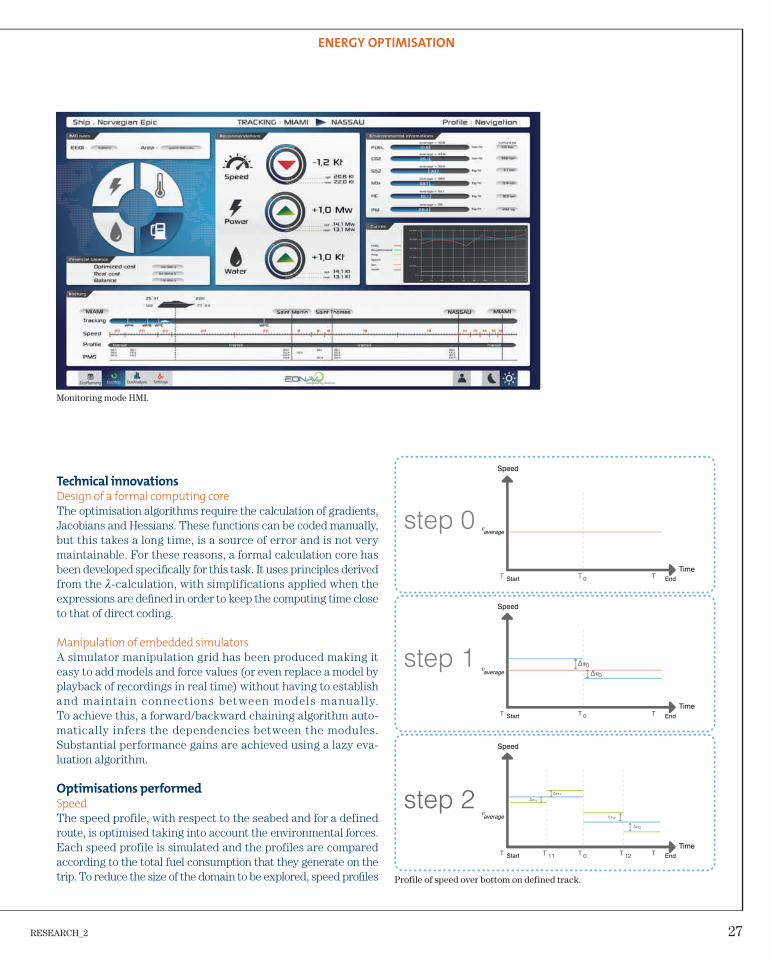
• analysis mode: for analysing and comparing completed voyages using the data recorded by the system. It contributes to the SEEMP imposed by the regulations. This mode can also be used to compare the model with the recorded data and detect any drift in the equipment.
Optimised operation of ships: simulations
and optimisations
Introduction
Changes in international regulations (target of a 20% reduction of CO2 emissions by 2020) and the lasting increase in the cost of oil are leading all shipbuilding industry leaders to propose innova-tions to improve the energy effi ciency of ships both in the design phase and in operational use.The EONAV optimised ship operation system for reducing energy consumption and emissions is a response to this concern with protection of the environment and with control of energy costs for ship operators. The emphasis placed by DCNS Research on energy optimisation conforms to its strategic development prio-rity for managing tomorrow’s energy issues and for broadening its range of innovating products.
Decision support tools (DST)
Optimisation
The EONAV system has been designed to help a crew optimise the energy management of a ship through various levers: optimum speed, confi guration of the generating plant and confi guration of the electrical substations for load-shedding. Other optimisations such as water production and trim can be added to these in order to improve performance, but speed management is a major factor, as it accounts for 60% to 80% of the total energy consumption of a ship.
DST energy model
The core of the application is based on a complex multiphysical energy model of the ship comprising the following components:• hydrodynamic model incorporating the environmental constraints;
AUTHORS: Charles-Édouard Cady and Christophe Gaufreton
As part of the EONAV FUI project, a decision support tool has been developed to provide recommendations
for optimising the control of a ship. The tool generates savings of around 2% on the fuel consumption of a
ship. Three types of optimisation are currently being developed: speed, electrical load-shedding and
generator load optimisation. The genericity of the architecture used enables other types of optimisation
(e.g. refrigeration, water production) to be accommodated.
RESEARCH_2 27
ENERGY OPTIMISATION
Technical innovations
Design of a formal computing core
The optimisation algorithms require the calculation of gradients, Jacobians and Hessians. These functions can be coded manually, but this takes a long time, is a source of error and is not very maintainable. For these reasons, a formal calculation core has been developed specifi cally for this task. It uses principles derived from the λ-calculation, with simplifications applied when the expressions are defi ned in order to keep the computing time close to that of direct coding.
Manipulation of embedded simulators
A simulator manipulation grid has been produced making it easy to add models and force values (or even replace a model by playback of recordings in real time) without having to establish and mainta in connections between models manual ly. To achieve this, a forward/backward chaining algorithm auto-matically infers the dependencies between the modules. Substantial performance gains are achieved using a lazy eva-luation algorithm.
Optimisations performed
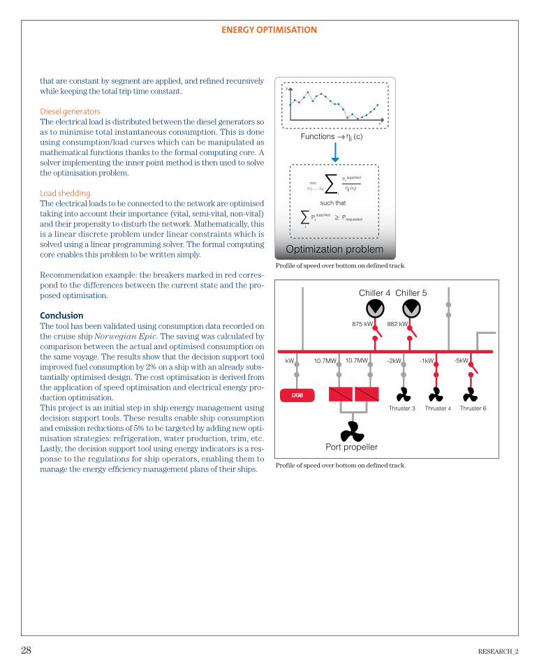
Speed
The speed profile, with respect to the seabed and for a defined route, is optimised taking into account the environmental forces. Each speed profile is simulated and the profiles are compared according to the total fuel consumption that they generate on the trip. To reduce the size of the domain to be explored, speed profi les
Monitoring mode HMI.
Profile of speed over bottom on defined track.
Speed
Start End
End
End
Start
Start
Time
Time
Time
Speed
Speed
average
average
average
28 RESEARCH_2
ENERGY OPTIMISATION
that are constant by segment are applied, and refi ned recursively while keeping the total trip time constant.
Diesel generators
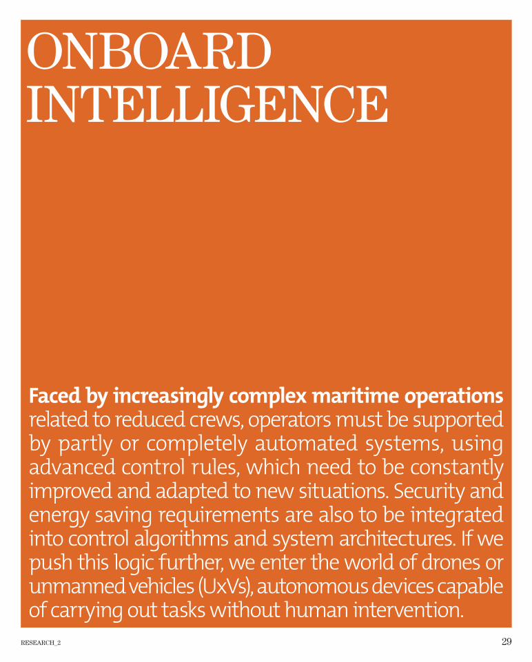
The electrical load is distributed between the diesel generators so as to minimise total instantaneous consumption. This is done using consumption/load curves which can be manipulated as mathematical functions thanks to the formal computing core. A solver implementing the inner point method is then used to solve the optimisation problem.
Load shedding
The electrical loads to be connected to the network are optimised taking into account their importance (vital, semi-vital, non-vital) and their propensity to disturb the network. Mathematically, this is a linear discrete problem under linear constraints which is solved using a linear programming solver. The formal computing core enables this problem to be written simply.
Recommendation example: the breakers marked in red corres-pond to the differences between the current state and the pro-posed optimisation.
Conclusion
The tool has been validated using consumption data recorded on the cruise ship Norwegian Epic. The saving was calculated by comparison between the actual and optimised consumption on the same voyage. The results show that the decision support tool improved fuel consumption by 2% on a ship with an already subs-tantially optimised design. The cost optimisation is derived from the application of speed optimisation and electrical energy pro-duction optimisation.This project is an initial step in ship energy management using decision support tools. These results enable ship consumption and emission reductions of 5% to be targeted by adding new opti-misation strategies: refrigeration, water production, trim, etc. Lastly, the decision support tool using energy indicators is a res-ponse to the regulations for ship operators, enabling them to manage the energy effi ciency management plans of their ships. Profile of speed over bottom on defined track.
Optimization problem
supplied
Functions
such that
suppliedrequested
Profile of speed over bottom on defined track.
RESEARCH_2 29
ONBOARD INTELLIGENCE
Faced by increasingly complex maritime operations
related to reduced crews, operators must be supported
by partly or completely automated systems, using
advanced control rules, which need to be constantly
improved and adapted to new situations. Security and
energy saving requirements are also to be integrated
into control algorithms and system architectures. If we
push this logic further, we enter the world of drones or
vehicles or objects in its environment. If an abnormal event is detected, the secondary computer takes control of the vehicle in order to make it safe. It is powered by a different, redundant power source from that of the main computer, so that it can be operational in the event of main system electrical failure. It is also linked with a remote supervision station via a dedicated communication link separate from the one used by the main computer, enabling an operator to take action in the event of failure of the main system communication link. The technology used for the communication link depends on the environment of the autonomous vehicle. If it operates on the surface, a micro-wave link is used, while for underwater operation the link is acoustic. The architecture may incorporate various sensors to avoid collisions with objects in its environment: radar, AIS, laser, video camera or sonar (the only sensor that can be used on underwater vehicles). The technologies of these sensors are complementary, increasing the vehicle’s perception of its environment.
Architecture of a guidance system for autonomous vehicles
Surface drones (Unmanned Surface Vehicles [USV]) and under-water drones (Unmanned Underwater Vehicles [UUV]), comple-menting aerial drones, have also seen their use become more widespread. They save manpower, either for carrying out repeti-tive tasks or for work in hostile environments. Since the early 2000s, combining its knowledge of marine platforms and auto-matic pilots, SIREHNA® (DCNS Research) has been contributing to this revolution through its work on guidance systems.
The guidance systems are the heart of autonomous vehicles. Developed by SIREHNA®’s engineers for marine drones, these software and hardware architectures are the fruit of a decade of research work and experimentation. USVs and UUVs are autono-mous vehicles that can be used in very diverse environments, ranging from secured zones (reserved exclusively for the drone) to zones of dense maritime traffi c (ports, commercial shipping routes, etc.). In the near future, the adaptability of the level of autonomy of these drones will enable military and civil users to vary their uses: as remote-controlled vehicles, as vehicles whose movements are monitored by remote operators, and as fully-autonomous vehicles. The architecture of their guidance sys-tems enables all navigation requirements to be met, while ensuring the safety of the vehicle and of its environment.
The guidance system consists of a main computer
(Command & Control) and a secondary computer
(Safety)
The main computer performs the functions related to navigation, for example by incorporating an autopilot. The secondary com-puter ensures the safety of the vehicle and of its environment: it checks the consistency of the commands output by the autopilot and detects vehicle failures and potential collisions with other
AUTHOR: Denis Gagneux
The use of aerial drones (Unmanned Aerial Vehicles) has grown exponentially over the last few years. Long
restricted to military uses, they are now becoming available in the civil sector.
RESEARCH_2 31
ONBOARD INTELLIGENCE
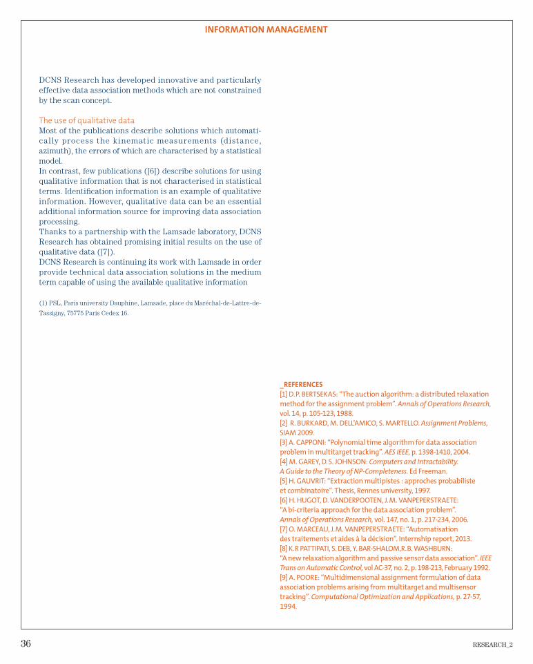
The architecture is currently deployed on a surface drone (Remorina) and on a non-tethered underwater model (MAX).
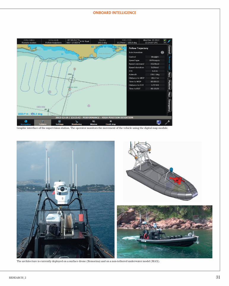
Graphic interface of the supervision station. The operator monitors the movement of the vehicle using the digital map module.
32 RESEARCH_2
RESEARCH_2 33
INFORMATION MANAGEMENT
The expanded use of electromagnetic, optronic and
acoustic sensors in diverse operational situations
has led to tremendous increases in data availability.
Effective information management has thus become
essential and now requires automated processes for
better localisation, identification, characterisation and
tracking. The underlying goal is to provide operators
with reliable, relevant and real-time information that
exposes the best possible decision.
34 RESEARCH_2
INFORMATION MANAGEMENT
New data association processing
solutions
( ).
describes the accumulation of scans:
(1)
A candidate hypothesis models a combination hypothesis for measurements that designate the same target. More precisely,
is defi ned as a subset of measurements from such that:
for any (2)
. (3)
(2) indicates that each candidate hypothesis cannot contain more than one measurement of each scan.(3) states that a candidate hypothesis contains at least one measurement.
Description of the problem
The data association function of a multisensor system (radar, infrared imager, etc.) is a critical technical component of search management. While each sensor supplies elementary information (positions, angles, identifi cations) describing the targets that it has detected, the data association function aims to combine information from sensors which designate the same target.
Mathematical modelling of the association problem
All the measurements are assumed to be made at fi xed times
with
(in reality, the measurements are generally asynchronous). At each time , the sensor supplies a set of measurements called a “scan”.
where
is the number of measurements received in scan and is the -th measurement received in scan . The composition of a meas-
urement depends on the sensor: for example, a 2D radar measures the distance and the azimuth angle of each potential target
AUTHOR: Olivier Marceau, Daniel Vanderpooten(1) and Jean-Michel Vanpeperstraete
The sensors on board a vessel supply descriptive measurements of the objects around the platform. The
data association function plays a key role in obtaining a synthetic representation of the environment of
the vessel on the basis of these measurements. Work at DCNS Research aims to propose data association
processing solutions which consume kinematic and qualitative information, without constraining
assumptions (scan assumption) about the structure of the sensor measurements on reception.
RESEARCH_2 35
INFORMATION MANAGEMENT
Tracks
Candidates hypotheses
Measurements
Figure 1. Examples of candidate hypotheses.
The output of the data association processing is a set con-sisting of candidate hypotheses.
(4)
The candidate hypotheses must form a partition of . In other words, each measurement of belongs to one, and only one, constituent candidate hypothesis of .
for any (5)
(6)
Tracks
Candidates hypotheses
Measurements
Figure 2. Example of partition.
The quality of a partition is assessed through the quality of its constituent candidate hypotheses . Each candi-date hypothesis of partition describes a combination of kinematic measurements which is more relevant the more consistent the measurements are with a kinematic behaviour of the targets to be detected. This kinematic con-sistency is assessed using a probability
.
The optimum partition is thus the one that maximises a con-sistency criterion of the following form ([9]):
(7)
where designates the set of partitions satisfying (4), (5) and (6).
Problem (7) is a discrete optimisation problem, which has no guaranteed exact solution in polynomial time for all instances where is strictly greater than 2 ([9]). This optimisation prob-lem in fact belongs to the category of NP-complete problems ([4]).
Solving the association problem
Equations (1) to (7) constitute the standard mathematical model of the data association problem. When the number of dimensions equals 2, the data association problem corresponds to the classic assignment problem, for which there are very effective exact polynomial algorithms (e.g. [1,2]…). Many publi-cations (e.g. [3,5,8,9]…) propose algorithms that are suboptimal but effi cient in terms of computing time when the number of dimensions is strictly greater than 2.
Despite the large number of solutions avai lable, DCNS Research is developing innovative solutions for associating data, for the following main reasons:• the scan structure constraint;• the use of qualitative data.
The scan structure constraint
The scan concept is central to the modelling of the association problem, and most algorithms make critical use of the concept.The scan models how the sensor measurements are presented to the data association processing. In the case of a rotating radar sensor, the scan is the set of measurements acquired during one complete antenna rotation. However, today opera-tional problems are arising where the asynchronism of the measurements renders the modelling constraint imposed by the scan structure problematic. To deal with this problem,
36 RESEARCH_2
INFORMATION MANAGEMENT
_REFERENCES
[1] D. P. BERTSEKAS: “The auction algorithm: a distributed relaxation
method for the assignment problem”. Annals of Operations Research,
vol. 14, p. 105-123, 1988.
[2] R. BURKARD, M. DELL’AMICO, S. MARTELLO. Assignment Problems,
SIAM 2009.
[3] A. CAPPONI: “Polynomial time algorithm for data association
problem in multitarget tracking”. AES IEEE, p. 1398-1410, 2004.
[4] M. GAREY, D. S. JOHNSON: Computers and Intractability.
A Guide to the Theory of NP-Completeness. Ed Freeman.
[5] H. GAUVRIT: “Extraction multipistes : approches probabiliste
et combinatoire”. Thesis, Rennes university, 1997.
[6] H. HUGOT, D. VANDERPOOTEN, J. M. VANPEPERSTRAETE:
“A bi-criteria approach for the data association problem”.
Annals of Operations Research, vol. 147, no. 1, p. 217-234, 2006.
[7] O. MARCEAU, J. M. VANPEPERSTRAETE: “Automatisation
des traitements et aides à la décision”. Internship report, 2013.
[8] K. R PATTIPATI, S. DEB, Y. BAR-SHALOM,R. B. WASHBURN:
“A new relaxation algorithm and passive sensor data association”. IEEE
Trans on Automatic Control, vol AC-37, no. 2, p. 198-213, February 1992.
[9] A. POORE: “Multidimensional assignment formulation of data
association problems arising from multitarget and multisensor
tracking”. Computational Optimization and Applications, p. 27-57,
1994.
DCNS Research has developed innovative and particularly effective data association methods which are not constrained by the scan concept.
The use of qualitative data
Most of the publications describe solutions which automati-cal ly process the k inematic measurements (distance, azimuth), the errors of which are characterised by a statistical model.In contrast, few publications ([6]) describe solutions for using qualitative information that is not characterised in statistical terms. Identifi cation information is an example of qualitative information. However, qualitative data can be an essential additional information source for improving data association processing.Thanks to a partnership with the Lamsade laboratory, DCNS Research has obtained promising initial results on the use of qualitative data ([7]).DCNS Research is continuing its work with Lamsade in order provide technical data association solutions in the medium term capable of using the available qualitative information
(1) PSL, Paris university Dauphine, Lamsade, place du Maréchal-de-Lattre-de-
Tassigny, 75775 Paris Cedex 16.
RESEARCH_2 37
INFORMATION MANAGEMENT
Tracking manoeuvring targets
in 3DAUTHOR: Dann Laneuville
GMIMM (Gaussian Mixture based IMM), which retains the most probable r hypotheses in each mode, whereas the IMM merges them all into a single hypothesis.
Today, the two most widely used models in an IMM fi lter are the NCV (Nearly Constant Velocity) model, which describes the uni form movement phases w ith state vector ([1]) X(t) = [x y z vx vy vy]’, and the NCT (Nearly Coordinated Turn) model for the coordinated turns in the horizontal plane ([1]) with state vector X(t) = [x y z vx vy ω]’ where ω is the turn rate in the plane. Until [3], the turns tracked by the IMM were in the horizontal plane. The recent approach developed in [3] also enables manoeuvres to be tracked in a vertical plane, but at present no f i lter satisfactori ly processes manoeuvres made simultaneously in the two planes (genui-nely 3D manoeuvres). That is the goal of our approach.
New approach
The two models above are described at present in Cartesian coordinates (CC) in the literature. We propose a new mixed representation: Cartesian for the position and spherical for the speed.
This gives state vector X(t) = [x y z s ψ θ]’ for the fi rst model, where s is the modulus of the speed, ψ et θ are the two angles defi ning the direction of the speed vector (see fi gure 1 below), and X(t) = [x y z s ψ θ ω1 ω2]’ for the second model, where ω1 is
Such manoeuvres, combined with the potential presence of false alarms, are a real problem for the tracking algorithm, which may “lag”, showing an estimation bias (loss of preci-sion), or even break lock, i.e. lose the track of the pursued object, obliging the system to regenerate the track after a pos-sible search phase in the event of tracking. In both cases, the loss of performance can prove fatal if a threatening target has to be engaged. Consequently, the availability of a robust, high-performance manoeuvring target tracking algorithm appears to be an essential component of surveillance and tracking systems. The purpose of this work is to study a new algorithm for tracking a manoeuvring target that can manoeuvre vigo-rously in two or three dimensions.
State of the art
The state of the art in manoeuvring target tracking algorithms is represented by the IMM (Interacting Multiple Model) fi lter introduced in the 1990s ([2]). This is a recursive algorithm using several Kalman fi lters in parallel, each dedicated to a particular phase of the trajectory, for example a fi lter for the uniform movement phases (constant speed = no manoeuvre) and a fi lter for the manoeuvre phases, such as uniform turns (in which the speed does not vary and the turn rate is constant). This fi lter has recently been revised to take strict account of the case of fi lters of different dimensions in each mode ([7]), as will be the case here, and improved in its approach with respect to the optimum filter ([5]) with the
Surveillance systems, the purpose of which is to determine the tactical situation in an extended zone
covered by search sensors, and tracking systems focusing on a particular object, are sometimes confronted
with particular situations in which certain objects in the scene are highly manoeuvrable. This may be the
case of a personal watercraft or an inflatable boat in the context of asymmetric threat countermeasures, or
of an ASBM (antiship ballistic missile) in the context of ABMD (antiballistic missile defence), for example.
38 RESEARCH_2
INFORMATION MANAGEMENT
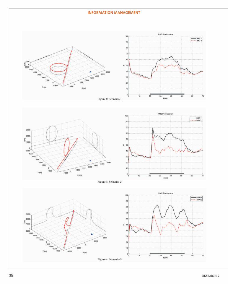
Figure 2. Scenario 1.
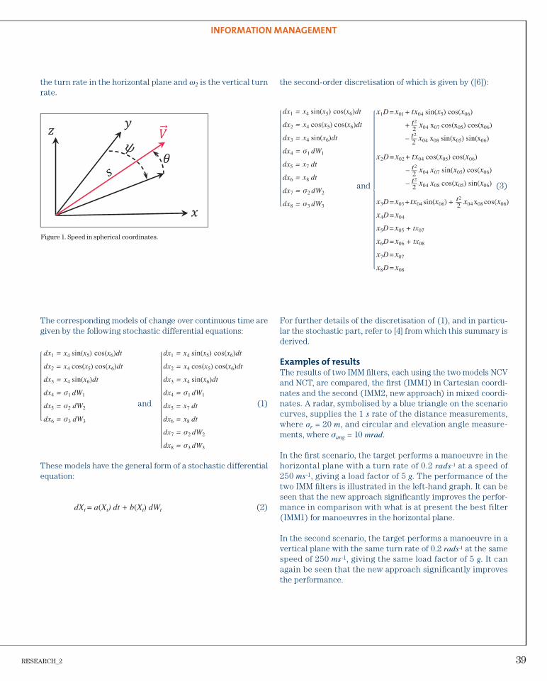
Figure 3. Scenario 2.
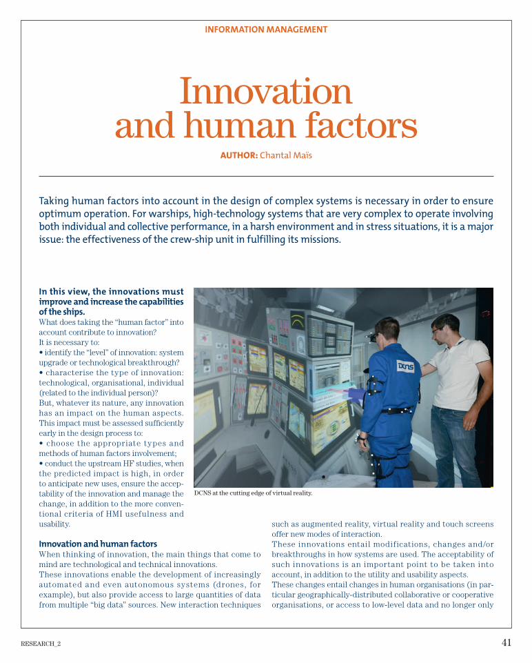
Figure 4. Scenario 3.
RESEARCH_2 39
INFORMATION MANAGEMENT
the turn rate in the horizontal plane and ω2 is the vertical turn rate.
Figure 1. Speed in spherical coordinates.
The corresponding models of change over continuous time are given by the following stochastic differential equations:
and (1)
These models have the general form of a stochastic differential equation:
dXt = a(Xt) dt + b(Xt) dWt (2)
the second-order discretisation of which is given by ([6]):
For further details of the discretisation of (1), and in particu-lar the stochastic part, refer to [4] from which this summary is derived.
Examples of results
The results of two IMM fi lters, each using the two models NCV and NCT, are compared, the fi rst (IMM1) in Cartesian coordi-nates and the second (IMM2, new approach) in mixed coordi-nates. A radar, symbolised by a blue triangle on the scenario curves, supplies the 1 s rate of the distance measurements, where σr = 20 m, and circular and elevation angle measure-ments, where σang = 10 mrad.
In the fi rst scenario, the target performs a manoeuvre in the horizontal plane with a turn rate of 0.2 rads-1 at a speed of 250 ms-1, giving a load factor of 5 g. The performance of the two IMM fi lters is illustrated in the left-hand graph. It can be seen that the new approach signifi cantly improves the perfor-mance in comparison with what is at present the best filter (IMM1) for manoeuvres in the horizontal plane.
In the second scenario, the target performs a manoeuvre in a vertical plane with the same turn rate of 0.2 rads-1 at the same speed of 250 ms-1, giving the same load factor of 5 g. It can again be seen that the new approach signifi cantly improves the performance.
dx1 = x4 sin(x5) cos(x6)dt
dx2 = x4 cos(x5) cos(x6)dt
dx3 = x4 sin(x6)dt
dx4 = σ1 dW1
dx5 = σ2 dW2
dx6 = σ3 dW3
dx1 = x4 sin(x5) cos(x6)dt
dx2 = x4 cos(x5) cos(x6)dt
dx3 = x4 sin(x6)dt
dx4 = σ1 dW1
dx5 = x7 dt
dx6 = x8 dt
dx7 = σ2 dW2
dx8 = σ3 dW3
dx1 = x4 sin(x5) cos(x6)dt
dx2 = x4 cos(x5) cos(x6)dt
dx3 = x4 sin(x6)dt
dx4 = σ1 dW1
dx5 = x7 dt
dx6 = x8 dt
dx7 = σ2 dW2
dx8 = σ3 dW3
x1D = x01 + tx04 sin(x5) cos(x06)
+ t2
—2
x04 x07 cos(x05) cos(x06)
– t2
—2
x04 x08 sin(x05) sin(x06)
x2D = x02 + tx04 cos(x05) cos(x06)
– t2
—2
x04 x07 sin(x05) cos(x06)
– t2
—2
x04 x08 cos(x05) sin(x06)
x3D = x03 + tx04 sin(x06) + t2
—2 x04 x08 cos(x06)
x4D = x04
x5D = x05 + tx07
x6D = x06 + tx08
x7D = x07
x8D = x08
(3)and
40 RESEARCH_2
INFORMATION MANAGEMENT
_REFERENCES
[1] Y. BAR-SHALOM, P. WILLETT and X. TIAN. Tracking and Data
Fusion. A Handbook of Algorithms. YBS Publishing, 2011.
[2] H. A. P. BLOM, Y. BAR-SHALOM. “The interacting multiple
model algorithm for systems with Markovian switching
coeffi cients”. IEEE Transactions on Automatic Control.
33, p. 780-783, August 1988.
[3] J. GLASS, W. D. BLAIR, Y. BAR-SHALOM. “IMM Estimators with
Unbiased Mixing for Tracking Targets Performing Coordinated
Turns”. Proceedings of IEEE Aerospace Conference, Big Sky,
United States, March 2013.
[4] D. LANEUVILLE. “New Models for 3D Maneuvering Target
Tracking”. Proceedings of IEEE Aerospace Conference, Big Sky,
United States, March 2014.
[5] D. LANEUVILLE, Y. BAR-SHALOM. “Maneuvering Target
Tracking: A Gaussian Mixture Based IMM Estimator”.
Proceedings of IEEE Aerospace Conference, Big Sky, United
States, March 2012.
[6] A. TOCINO and J. VIGO-AGUIAR. “New Itô-Taylor expansion”.
Journal of Computational and Applied Mathematics, 158,
p. 169-185, 2003.
[7] T. YUAN, Y. BAR-SHALOM, P. WILLETT, E. MOZESON,
S. POLLAK and D. HARDIMAN. “A multiple IMM approach with
unbiased mixing for thrusting projectiles”. IEEE Transactions
on Aerospace and Electronic Systems, 48(4):3250-3267,
October 2012.
In the third scenario, the target performs a 3D manoeuvre, i.e. in both the horizontal and vertical planes, with a turn rate of 0.2 rads-1 in both planes and at a speed of 250 ms-1, giving a load factor of 7 g. It can again be seen that the new approach behaves as well as previously (manoeuvre in one of the two planes) and signifi cantly improves the performance.
Conclusions and prospects
We have presented a new approach to modelling the manoeuvres of a target, which not only improves performance on coordinated turn manoeuvres in the horizontal or vertical plane, but also maintains the same level of performance on genuinely 3D manoeuvres. This approach, more natural and more physical than Cartesian coordinates for modelling the manoeuvres of a moving object, consequently appears to be very promising for manoeuvring target tracking applications. Subsequent work consists in incorporating it into a tracking algorithm in order to test it in a multitarget environment with false alarms and detec-tion gaps.
RESEARCH_2 41
INFORMATION MANAGEMENT
Innovation and human factors
AUTHOR: Chantal Maïs
such as augmented reality, virtual reality and touch screens offer new modes of interaction.These innovations entail modifications, changes and/or breakthroughs in how systems are used. The acceptability of such innovations is an important point to be taken into account, in addition to the utility and usability aspects.These changes entail changes in human organisations (in par-ticular geographically-distributed collaborative or cooperative organisations, or access to low-level data and no longer only
In this view, the innovations must
improve and increase the capabilities
of the ships.
What does taking the “human factor” into account contribute to innovation?It is necessary to:• identify the “level” of innovation: system upgrade or technological breakthrough?• characterise the type of innovation: technological, organisational, individual (related to the individual person)?But, whatever its nature, any innovation has an impact on the human aspects. This impact must be assessed suffi ciently early in the design process to:• choose the appropriate types and methods of human factors involvement;• conduct the upstream HF studies, when the predicted impact is high, in order to anticipate new uses, ensure the accep-tability of the innovation and manage the change, in addition to the more conven-tional criteria of HMI usefulness and usability.
Innovation and human factors
When thinking of innovation, the main things that come to mind are technological and technical innovations.These innovations enable the development of increasingly automated and even autonomous systems (drones, for example), but also provide access to large quantities of data from multiple “big data” sources. New interaction techniques
Taking human factors into account in the design of complex systems is necessary in order to ensure
optimum operation. For warships, high-technology systems that are very complex to operate involving
both individual and collective performance, in a harsh environment and in stress situations, it is a major
issue: the effectiveness of the crew-ship unit in fulfilling its missions.
DCNS at the cutting edge of virtual reality.
42 RESEARCH_2
INFORMATION MANAGEMENT
summary data for the decision-making levels, etc.), and changes in the allocation of tasks between individuals (poten-tially with reduction of workforce) or in practices.But innovation is not limited to technological innovation. Any change at the level of the individual (changes in tasks, change in profile), at the level of a collective (workforce reduction, decentralised organisation), or at the level of the company (company development) can also be seen as an innovation, the impacts of which on the future users must be analysed and anticipated, incorporating the following data:• the various human aspects – anthropometry, physiology, cognition, conation, sociology, etc. – are not mutually inde-pendent. Their interactions in part determine the behaviour (and potentially the performance) of the users. For example, the confi dence users have in the system can modify how they interact with the system;• individuals differ from each other in the various aspects. This interindividual variability generates different require-ments, needs and behaviours;
• individuals change over time in the various aspects. As they gain experience, they acquire new knowledge, modify their cognitive structures, etc.In a user-centred approach, it is necessary to predict the impacts on the users, including on future practices, through a validation procedure (mock-up/evaluation) with the users as far upstream as possible.At DCNS, a company with a high level of technicality, innova-tion is most often considered in terms of technology. Taking human factors into account not only guides innovation, but is also a source of innovation!
RESEARCH_2 43
STEALTH AND ANTENNA INTEGRATION
How can you be somewhere without others being
aware of your presence? How can you prevent distur-
bing the environment through which you are moving?
Whether in the field of electromagnetics or acoustics,
there are several technological solutions to choose
from. These call for special materials, carefully designed
forms, positionings and judicious decoupling. Seeking
and identifying these solutions requires upstream
modelling of the phenomena involved, using tools and
methodologies capable of being updated to keep pace
with threats and analytical needs.
44 RESEARCH_2
STEALTH AND ANTENNA INTEGRATION
response of the plate and the pressure radiated in the fl uid in the time domain. A schematic representation of the solving principle is shown in fi gure 1.
Application to an immersed infi nite plate
The method used is validated by comparison with a plate in a vacuum, for which there are analytical solutions [3]. The study of vibration on an immersed plate shows the effect of the fl uid, the dispersion of the plate waves and the fl uid/solid interface waves. The study of the radiated pressure shows directivity of the radiation and propagation of the waves in the plate before being radiated.
An example of simulation of an immersed aluminium plate is shown in fi gure 2. The pressure levels in the fl uid at four dif-ferent times can be seen (left to right and top to bottom: t = 0.23 ms, t = 1.40 ms, t = 2.79 ms and t = 6.12 ms). The pla-nar plate is located along z = 0, so its edge is represented by the black dotted line. The exciting force consists of a pulse at (t = 0, z = 0). The colour map shows the pressure levels in the fl uid. The propagation of the waves in the fl uid can be obser-ved in the four panels. Four virtual hydrophones are placed in
Vibroacoustic radiation by plates in transient states
Solving method
To study the vibrations and the acoustic radiation of an immersed structure excited by a transient source, a simple structure is considered first: an infinite plate. The plate is immersed and subjected to a point pulsed excitation. The movement of the plate is expressed by the Love-Kirchhoff equation [1,2]:
where D is the bending stiffness of the plate, and h are res-pectively the density and thickness of the plate, ω is the angu-lar frequency, ξ is a structural damping term, w(r,t) represents the displacement of the plate as a function of the distance from the excitation source and time, f0 is the amplitude of the exciting force at location r0 and p(r,t) is the parietal pressure. Particular attention must be paid to the viscoelastic damping model, which must obey the causality principle. Solving this equation for the dynamics of thin plates in harmonic states gives the movement of the plate in the frequency domain. An inverse Fourier transform is then applied to obtain the pulse
AUTHORS: Thomas Leissing, Roch Scherrer and Christian Audoly
The use of acoustic waves at sea for detection of enemy forces by means of passive sonar has been
widespread for decades, and sonar technology is evolving constantly. The upgrading of passive sonars,
now capable of analysing transient noise, makes it necessary to optimise acoustic discretion in non-
steady-state conditions. DCNS must consequently be capable of specifying transient acoustic discretion
requirements for equipment and their support structures installed on vessels. In this context, DCNS
Research is working on the study of vibroacoustic radiation mechanisms of structures in transient states,
for example in a doctoral thesis in partnership with the INSA-Lyon acoustic vibration laboratory. The
objective of this study is to improve knowledge in order to represent the mechanisms of vibroacoustic
radiation of structures in transient states in terms of radiation sources, transfers and factors.
RESEARCH_2 45
STEALTH AND ANTENNA INTEGRATION
Figure 1. Schematic representation of the solving method.
Figure 2. Simulation of the pressure field radiated by an immersed infiDinite plate excited by a point force.
Unknown transfer functionAnswer
Answer
Transfer function known
Fourier Transform
Inverse Fourier Transform
Source
Source
46 RESEARCH_2
_REFERENCES
[1] M. C. JUNGER, D. FIET: Sound, structures and Their
Interaction. Second ed., Cambridge: The MIT Press, p. 235-250,
1986.
[2] X. L. BAO, H. FRANKLIN, P. K. RAJU, H. UBERALL: “The splitting
of dispersion curves for plates fl uid-loaded on both sides”.
Journal of the Acoustical Society of America. 102 (2), 1997.
[3] R. SCHERRER, L. MAXIT, J.L. GUYADER, C. AUDOLY,
M. BERTINIER: Analysis of the Sound Radiated by a Heavy Fluid
Loaded Structure Excited by an Impulsive Force. Internoise
2013, Innsbruck, Austria, September 2013.
the fluid medium; they are represented by the filled black circles. The signals received at these points are shown on time/amplitude graphs. It can be seen that the temporal cha-racteristics of the signals differ greatly according to the dis-tance between the excitation point and the observation point. The signal received by the nearest receiver (bottom-left) is very short, practically a pulse, whereas the signal observed by the receiver located bottom-right has a smaller amplitude, a longer duration and a more complex frequency content. This simulation reveals, for a simple case, various physical pro-cesses that would be difficult to identify and interpret in a frequency representation.
Prospects
The case of the infinite plate can be used to validate the models and the numerical methods developed, but is not suffi -ciently representative of the complex mechanical systems on board ships. In order to approach as closely as possible to real structures, the case of fi nite plates, beams and their coupling is also being processed by methods similar to those described here. In addition, experiments are being carried out on immer-sed plates in an acoustic tank; these measurements will be used to validate the simulation models developed in this study. Fine-tuning and experimental validation of these models and tools will enable the DCNS Research teams to obtain finer characterisation of the vibration and radiation processes of structures subjected to pulsed excitations. Eventually, it will be possible to apply these methods to the design of ships for acoustic discretion in transient states.
RESEARCH_2 47
PRODUCTIVITY AND COMPETITIVENESS OF INDUSTRIAL PROCESSESIndustrial processes affect all product manufacturing
activities and components, broadly encompassing the
choice of materials, manufacturing techniques, assem-
bly and appropriate testing methods. Such processes
include the extensive use of virtual or augmented reality,
i.e. reliance on modelling and visualisation methods to
choose the best path forward, well upstream of the pro-
totype phase. Moreover, the changes taking place in the
way overall production chains are organised, in incorpo-
rating new manufacturing technologies, has prompted
research into the “future factory” and the “extended
factory” within many industrial sectors.
48 RESEARCH_2
PRODUCTIVITY AND COMPETITIVENESS OF INDUSTRIAL PROCESSES
welding without fi ller metal, which eliminates the disadvantages associated with metal fusion. While there are still many scientifi c and technological locks, the FSW is a mature technology for homo-geneous and heterogeneous aluminium alloys [1] assembly. The main applications in the field of shipbuilding concern assembly extruded shapes to form stiff fl oors [2]. Studies [3, 4] have demons-trated the importance of this process in low alloy steels for a thic-kness of about 6 mm to 12 mm, for the grain refi nement in heat affected zone (HAZ), an enhancement of the metallurgical welda-bility with regard to arc welding processes, and producing no wel-ding fumes, particularly containing hexavalent chromium. However, the results are derived from laboratory works on small specimens and do not demonstrate the industrial feasibility, taking into account the operating conditions in general and the use of tool with limited life (based tungsten-molybdenum) in particular. The recent developments of technologies coming from drilling tools (poly-crystalline boron nitrides – PCBN – doped W-Re), proposed by MegaStir lead to a technology breakthroughs [5]. Studies related to the use of these promising tools are limited to the work of the team behind the tool invention and limited mechanical perfor-mance materials [6]. To our knowledge, concerning welding of HYS steels required especially for shipbuilding, no study has been published to date.
Evaluation of friction stir welding (FSW) on high yield
strength steels for shipbuilding
Introduction
The competitive market of naval vessels requires more effi cient designs and manufacturing conditions in order to increase indus-trial and service performances. In particular the improving of the manufacturing conditions and the weight saving can be achieved by innovative design and processes. The use of performance mate-rials such as high yield strength (HYS) steels in shipbuilding (hull, superstructures, fl oatboard, propellers…) is a solution which allows a signifi cant weight saving by reducing the structures thicknesses. The manufacturing processes must accordingly adapt to the cha-racteristics of these grades. In this context, the development of innovative welding processes must also be conducted ensuring the quality of assemblies: limitation of weld defects, limitation of distor-tions and improving the flatness of structures, improvement of hygiene and safety with regard to manufacturing processes, better controllability, improvement of serviceability and repairing.
The fusion welding processes used in shipyards could require pre-heating, generally a fi ller metal, and lead currently to defects (lack of fusion, porosity, inclusions, cold cracking) or geometric defects on the surface (undercuts…), as well as distortions of structures. These defects undertake works, for repairing and/or fi nishing. The friction stir welding is an alternative method that uses solid-phase
AUTHORS: Guillaume Rückert, Myriam Chargy, François Cortial and François Jorez
FSW process has been evaluated on three shipbuilding steels (DH36, S690QL and 80HLES steels) by fully-
penetrated butt welds on 8 mm thick plates. Non destructive tests were carried out to highlight the
presence of intrinsic defects known for the welding process (e.g. kissing bond). The validated inspection
methodology (volume and surface testing) confirm the integrity of welds and the absence of geometrical
defects for examinations and mechanical tests as part of a qualification procedure.
RESEARCH_2 49
PRODUCTIVITY AND COMPETITIVENESS OF INDUSTRIAL PROCESSES
This study presents an evaluation of this innovative welding pro-cess for both civil and military shipbuilding applications. The main objective is to demonstrate that the FSW process technically and economically meets the specific requirements of the shipyards. Indeed, the introduction of this process in the workshop can be done only if its interest is demonstrated in terms of quality and manufacturing costs, controllability, health and safety of personnel dealing with proven and economically viable processes. It is there-fore necessary to verify that the process is robust and repeatable, and that it can satisfy the required performances of the assemblies. The present study focused on three steels currently used for French naval application: two high yield strength steels (S690QL and 80HLES, a French grade close to HY100) and a DH36 steel, employed for hull and structures. The presentation provides a cha-racterisation of the welded joints for optimised welding parameters and a complementary analysis to consider a future industrialisation of the FSW process in our shipyards.
Experimental procedure
Materials
Three grades of steel (two high yield strength steels and one construction steel) used for hull and structure applications have been selected for this study according to their respective mecha-nical properties:• DH36 steel, a structural steel for hull according to Bureau Veritas NR 216 [7];• S690QL steel, a structural steel according to standard EN 10025-6 [8];• 80HLES steel, a French equivalent grade of HY-100 steel for hull and structures.
The following tables give respectively guaranteed values for mechanical properties and chemical composition for each grade.
Table 1. Guaranteed values for mechanical properties for DH36, S690QL and 80HLES steels
The butt welding tests (with full penetration) have been performed
with a Gantry machine on 1,500 x 150 x 8 mm plates on the three grades, joined together in the lengthwise (rolling direction). Friction stir-tool in PCBN based material comprises a threaded shoulder (25 mm diameter) prolonged by an 8 mm long threaded conical pin.
Non-destructive tests (NDT) and mechanical tests
Characterisation tests were carried out in order to compare the performance of the FSW process with arc-welding processes for which the expected performances are known. The introduction of welding processes in manufacturing requires a welding pro-cedure qualification (WPQ), the rules and requirements are governed by codes or standards. For shipbuilding steels, the ISO 15614-1 standard [9], dealing with the qualifi cation of welding procedures for arc welding of steels offers a level of minimum requirements.
NDT required in this context are two complementary types of tests, i.e. volume testing and surface testing on 100% of the weld. These tests are always preceded by a visual inspection which, in the case of FSW, can identify unacceptable defects like partial penetration type, or lack of recovery, burrs… For the volume part, digital radiographic testing (X-rays) are preferred to ultra-sonic testing because of the welded thickness. Indeed, for 8 mm thick welds, the resolution of the X-rays is much better. For sur-face measurements on the upper and lower surfaces of the weld, penetrant and magnetic particle testings are performed. The surface of the weld can cause background noise, especially for dye penetrant testing. It is often necessary to grind the surfaces before examinations.
Destructive tests are performed to ensure that the weld does not cause signifi cant change in the characteristics of the assembly. Transverse tensile tests (two specimens), transverse bend tests (two specimens per face – upper and lower –, bending angle 180°) impact tests (V-notch at –20 °C) and Vickers hardness (HV5) were carried out according to [9] and associated standards cited by this standard. For impact tests, specimens are machined on the nugget and the thermo-mechanically affected zone, i.e. TMAZ (three specimens per batch). For hardness tests, two rows of indentations were made at a depth of up to 2 mm below the upper and lower surfaces of the welded joint (at least 3 individual inden-tations in each area). In addition, complementary longitudinal tensile tests have been carried out on the nugget in order to cha-racterise the stirred zone.
Results
NDT tests
Specimens welded during preliminary testing dedicated to set-tings of welding parameters have been used to validate that radiographic testing is relevant to indicate the volume defects which may appear in FSW such as internal voids. Defects such as kissing bonds, which are not detected by visual examination
50 RESEARCH_2
PRODUCTIVITY AND COMPETITIVENESS OF INDUSTRIAL PROCESSES
(fi gure 1.a) or penetrant testing, are revealed through magnetic particles testing. Figure 1.b illustrates this observation by the presence of a black vertical line in the middle of the weld corres-ponding to a discontinuity of the magnetic fi eld lines. It could be related to incoherence in the microstructure between the two edges to be welded, confi rmed by micrographics on cross-section coupons (fi gure 1.c). The ACFM (alternating current fi eld measu-rement) method is an alternative method to magnetic particles testing for kissing bond examination. This typical defect in FSW caused particular developments in innovative techniques for alu-minum alloys. The magnetic nature of the steel allows the appli-cation of simple and proven methods to ensure the absence of kissing bond.
Destructive tests
In this study, the selected areas for mechanical tests on each grade of steels are free of NDT indications. Tensile tests on transverse specimens lead systematically to a failure on the base material. For DH36 steel, the two specimens exhibit res-pectively tensile strength values at 512 and 513 MPa (742 and 744 ksi) at 20 °C. The ultimate tensile strength reached on lon-gitudinal tensile specimens (on nugget) is about 700-712 MPa (101-103 ksi). It confi rms a signifi cant gap in mechanical beha-viour between the base material and the nugget, explained by a severe thermo-mechanical cycle constituting a Widmanstätten microstructure, as shown in fi gure 2.a. Elongations values are not too much affected (22% and 24% in the nugget) and slightly higher than the requirements for the base material (i.e. 21%). We can expect such behaviour for welded S690QL and 80HLES steels, each exhibiting a very hard martensitic structure as shown in figure 2 for 80HLES steel and confirmed latter by hardness tests (table 4) for both steels.
Bend tests are discriminating enough for kissing bond (when the upper surface is stretched); without defect, no indication upper than 3 mm, with respect to the standard [9], is noticeable.
Macroscopic examinations on the three welded steels conclude to a defect free nugget. No internal or geometric defects were noted in observation areas. In retreating side, it could appear, as shown in fi gure 3 for 80HLES steel, a lack of thickness, but well below the acceptance criterion (i.e. 0.1 t from [9]). Burrs may appear locally (corresponding with areas exhibiting a lack of thickness). If the lack is acceptable, we just remove the burr by grinding.
Impact tests results are given in table 3 for DH36 steel. Values in TMAZ are slightly lower in retreating side (two individual values around 35 J), probably associated with the conditions of the bond formation to the back of the stir tool. The base mate-rial exhibits values upper than 70 J. Values obtained on the friction stirred weld are systematically lower than those for base material. In arc welding, the mean values of absorbed energy vary between 40 J and 100 J, according to the processes
and welding energies. The FSW process leads to results with similar magnitude than arc welding process, consistent with the elongation values previously identified and consistent with requirements of Bureau Veritas (i.e. 34 J at –20 °C) [7].
Table 3. Impact test (V-notch) results (individual and mean values) for DH36 steel at –20 °C
Nugget TMAZ
Middle
upper side
Middle
lower side
TMAZ/Nugget interface
advancing side
TMAZ/Nugget interface
retreating side
79 71 42 61 57 78 50 45 51 35 59 33
64 65 49 42
Hardness tests results are shown in table 4 for the three welded steels. These results indicate a hardening in nugget and affected zones (HAZ/TMAZ) related to thermal and mechanical conditions imposed during friction stir welding, even more pronounced when the steel is susceptible to quen-ching (as shown in figure 2.b for 80HLES steel). However, large increases in hardness for S690QL and 80HLES steels are compatible with the requirements specifi ed in the standard [7]. There is no signifi cant difference in results between advancing and retreating side. The dispersion in results into the nugget, particularly between upper and lower rows, even in a same row (e.g. S690QL steel), can be explained by the coexistence of different mixed areas.
(a) (b) (c)
Figure 1. Kissing bond defect on DH36 steel; no indication by visual examination of the lower surface (a), indication (black vertical line in the middle of the weld) in magnetic particles testing on the lower surface (b), observation on cross-section micrograph (c).
(a) (b)
Figure 2. Micrograph on friction stirred nuggets; DH36 (a) and 80HLES (b).
Figure 3. Macrograph of the friction stirred weld on 80HLES steel (advancing side on left side).
RESEARCH_2 51
PRODUCTIVITY AND COMPETITIVENESS OF INDUSTRIAL PROCESSES
Table 4. Hardness test results (HV5) in friction-stirred welds for DH36, S690QL and 80HLES steels
Grade Location
Advancing side Retreating side Permitted
maximum
value [7]BM HAZ / TMAZ Nugget HAZ / TMAZ BM
DH36
Upper
row
178
172
178
187
202
229
214
202
211
220
212
221
192
181
186380
Lower
row
172
169
169
188
195
202
202
205
199
207
198
188
174
173
176
S690QL
Upper
row
279
277
268
374
374
386
393
416
413
399
386
378
277
290
294450
Lower
row
279
263
271
391
445
435
395
418
430
430
440
375
268
266
269
80HLES
Upper
row
277
275
276
410
441
433
421
410
431
440
438
433
275
275
280450
Lower
row
279
277
268
374
386
393
416
413
399
386
383
378
277
290
294
Conclusions
Preliminary investigations on three friction-stir welded steels were performed in order to confi rm the applicability of the inno-vative FSW process for shipbuilding steels.The main results of this study are:– NDT tests (volume and surface testing) are proposed for the examination of the qualifi cation coupons and manufacturing assemblies; in particular, the application of magnetic particles testing which is a common and simple to perform accurate and relevant test to the detection of defects such as kissing bond;– for DH36 steel, a complete character isation has been performed and concludes on a good behaviour of the welded joints, compatible with the minimum charges required in shipbuilding.– the first partial results on S690QL and 80HLES steels are encouraging; welds can be free from defects and hardness rows display results in compliance with the requirements. However, microscopic observations exhibit complex structures related to the thermo-mechanical cycle and the primary structures of steels that can lead, in the worst case, to an excessive fragility of the weld. It requires further investigation in progress to understand the formation mechanisms of the different areas and accordingly optimise the welding parameters.
Acknowledgements
This study is part of SIPSAN project supported by IRT Jules Verne (French Institute in Research and Technology in Advanced Manufacturing Technologies for Composite, Metallic and Hybrid Structures). Authors wish to associate the industrial and academic partners of this project, respectively DCNS, STX France, Bureau Veritas, GeM Institute (UMR CNRS-ECN-Nantes University 6183); IMN Institute (UMR CNRS-Nantes University 6502).Authors wish also to thank gratefully MegaStir (Provo, USA) for the achievement of friction stirred welds.
_REFERENCES
[1] R. RAI, A. DE, H. K. D. H. BHADESHIA ET T. DEBROY. “Review: friction
stir welding tools, Science and Technology of Welding and Joining”,
Volume 16, no. 4, p. 325-342, February 2011.
[2] K. J. COLLIGAN, M. T. SMITHERMAN, S. B. HOYLE. “Low-cost friction
stir welding for littoral combat ship applications”. Naval Engineers
Journal, March 2009.
[3] T. J. LIENERT, W. L. STELLWAG, B. B. GRIMMETT, R. W WARKE. “Friction
[4] T. SHINODA, H. TAKEGAMI et al. Development of FSW Process for
Steel Assemble to Shipbuilding and Off shore Structure. Proceedings
of the 15th International Off shore and Polar Engineering Conference,
Seoul, Korea, 19-24 June 2005.
[5] J. DEFALCO, R. STEEL. “Friction stir process now welds steel pipe”.
Welding Journal, Volume 88, no. 5, p. 44-48, May 2009.
[6] C. C. TUTUM, J. H. HATTEL. “Numerical optimisation of friction
stir welding: Review of future challenges”. Science and Technology
of Welding and Joining, Volume 16, no. 4, p. 318, 2011.
[7] NR 216 DT R06 E. “Rules on Materials and Welding for the
Classifi cation of Marine Units”, edited by Bureau Veritas,
February 2013.
[8] EN 10025-6 standard: Produits laminés à chaud en aciers de
construction – Partie 5 : conditions techniques de livraison pour
les aciers de construction à résistance améliorée à la corrosion
atmosphérique (Hot rolled products of structural steels – Part 5:
Technical delivery conditions for structural steels with improved
atmospheric corrosion resistance), edited by Afnor, March 2005.
[9] ISO 15614-1 standard: Descriptif et qualifi cation d’un mode
opératoire de soudage pour les matériaux métalliques – Épreuve
de qualifi cation d’un mode opératoire de soudage – Partie 1 : soudage
à l’arc et aux gaz des aciers et soudage à l’arc des nickels et alliages
de nickel (Specifi cation and qualifi cation of welding procedures for
metallic materials – Welding procedure test – Part 1: Arc and gas
welding of steels and arc welding of nickel and nickel alloys), edited
by Afnor, February 2005.
52 RESEARCH_2
PRODUCTIVITY AND COMPETITIVENESS OF INDUSTRIAL PROCESSES
positive by the various entities involved: ultrasonic examination provides greater flexibility in the manufacturing process while ensuring detection sensitivity at least equal to that of radiography.
A similar approach is now introduced for certain joints in the hulls of surface ships. The diffi culty in this case is to ensure examination of the whole volume required on non-fl ush joints of low thickness.
In parallel with this work, DCNS Research is continuing to develop TOFD, for example by incorporating multi-element technology [3]. The beam focusing and defl ection capabilities enable new applica-tions to be considered, such as examination of austenitic joints [4] and inspection of very thick joints (up to 200 mm).
The development of TOFD at DCNS
TOFD (Time of Flight Diffraction) is an ultrasonography technique using two transducers (a transmitter and a receiver) placed either side of a weld (fi gure 1). In combination with an encoding system, this system can rapidly obtain an image of the weld, which is com-parable to a cross-section view of the weld (fi gure 2).
This technique originated in the 1980s in the United Kingdom. It has been under study at DCNS since the 1990s and used for the fi rst assessments on onboard nuclear steam supply systems from 1995 (fi gure 3). Many other developments have taken place since then, and the TOFD technique is now widely employed when necessary in the context of in-service monitoring (fi gure 4).
For hulls, discussions with the UK MoD were initiated in 1995, in which one of the major topics was the replacement of radiography for hull weld inspection. The discussions resulted in various bench-marks for comparing and improving testing procedures and equip-ment. At the time, DCNS carried out various statistical studies [1] demonstrating the high level of effectiveness of the ultrasonic technique. These studies, backed by all the studies conducted during the same period in other fi elds (petrochemicals, offshore, etc.), led DCNS to propose the TOFD ultrasonic technique to French defence procurement agency DGA as an alternative to radiography for submarine hull weld inspection. Reduction of radiation sources was of course a major objective, but the producti-vity gain obtained by increased concurrent activity in the construc-tion phase was the other important factor.
Coordinated by DCNS Research, a team combining ultrasonics experts, engineering and the production site compiled a suppor-ting documentation package which was finally accepted by the customer in 2012 (figure 5) [2]. Feedback is today considered
AUTHOR: Patrick Recolin
One of the missions of DCNS Research is the development of new non-destructive testing techniques in the
laboratory followed by their deployment on the Group’s production and maintenance sites. The growing
use of the TOFD ultrasonic technique is an illustration of this.
_REFERENCES
[1] P. RECOLIN, S. RIVALIN, Y. LEZIN. Utilisation de TOFD pour
le contrôle des joints de coque, COFREND 2001.
[2] B. MARIE, P. RECOLIN, B. LEYRONAS, A. LEBIEZ. Remplacement
de la gammagraphie par les ultrasons sur des soudures
de coques, COFREND 2011.
[3] S. RIVALIN, P. RECOLIN. Application de la technologie des
capteurs ultrasonores multi-éléments au suivi de soudures
de collecteur vapeur, COFREND 2005.
[4] P. RECOLIN, S. RIVALIN, B. MARIE. Examen partiel en TOFD
d’une soudure austénitique, COFREND 2011.
RESEARCH_2 53
PRODUCTIVITY AND COMPETITIVENESS OF INDUSTRIAL PROCESSES
Figure 3. First assessments.
Figure 6. Use of multi-elements in TOFD.
Figure 5. Inspection of a hull joint.
Figure 4. Inspection of the containment of the aircraft carrier.
Figure 2. TOFD image of a welded joint.Figure 1. Typical TOFD configuration.
– Control TOFD L45 L60
54 RESEARCH_2
PRODUCTIVITY AND COMPETITIVENESS OF INDUSTRIAL PROCESSES
Biofilms and corrosion of corrosion-resistant alloys
in sea water
Feedback from users, including DCNS, shows that this type of corrosion occurs in all the oceans and seas around the world and at any time of year. It is characterised by an increase in the free corrosion potential and the generation of a corrosion cur-rent between the “crevice” zone (seal, f lange, pump, heat exchanger, etc.) and the metal surface outside the crevice, as shown in fi gure 1.
These increases in potential and current have been eliminated by application of biocides. This provided evidence of the involvement of biofi lms formed in the systems, leading to a focusing of research on a more specifi c study.
The objective of this project, supported by French defence procurement agency DGA through the REI exploratory research and innovation scheme, was to understand the role of the biofi lm in the crevice corrosion processes on Inconel 625. The project involved multidisciplinary characterisa-tion of biofi lms formed on alloy Inconel 625 under controlled conditions leading to active or inactive biofi lms. The diversity of bacterial species in each biof i lm was analysed, as wel l as its phyto-planktonic diversity, its chemical composition (lipids, carbohydrates, amino acids, mineral and
Nickel-based alloys (e.g. Inconel 625 – base Ni, 22% Cr, 9% Mo, Nb) and austenitic-ferritic duplex steels
have been used extensively for applications in sea water since the 1980s. These alloys are specifically
resistant to all forms of uniform corrosion. Nevertheless, they may be sensitive to localised corrosion and
in particular to crevice corrosion.
STRUCTURAL ORGANISATION
Bacterial abundanceMicroscopic Observation
Area Coverage
ENZYMATIC ACTIVITIES
Lipase, glucosidase aminopeptidase
BACTERIAL DIVERSITY DNA fingerprinting
Taxonomic Identification
PHYTOPLANKTON DIVERSITY
GLOBALCHEMICAL COMPOSITION
Lipids, glucids , Amino acids
Inorganic elementsHydrogen peroxides ( H2O2 )
Figure 1. Crevice corrosion of alloy 625 in natural sea water on a flange and at the metal/seal contact.
Figure 2. Test plan.
Multidisciplinary Characterization
RESEARCH_2 55
PRODUCTIVITY AND COMPETITIVENESS OF INDUSTRIAL PROCESSES
metallic constituents, oxidising molecules) and its spatial orga-nisation, according to the test plan in fi gure 2.
The fi rst stage of the study consisted in conditioning surfaces using an electrochemical method in order to obtain “active” biofi lms on samples showing a high cathode current and “inac-tive” biofi lms on samples showing an open-circuit potential of 300 mV/SCE but a low cathode current.
Nearly 700 samples were conditioned for analysis. All the bio-fi lm characterisation analyses illustrated in fi gure 3 were per-for med on sa mples at d i f ferent t i mes of year (f rom November 2011 to end-2012).
The multidisciplinary characterisation observed differences between “active” and “inactive” biofi lms, including:• higher concentration of microorganisms in the “active” bio-fi lms, associated with greater coverage of the surface of these active samples in the form of aggregates;• greater diversity of bacterial communities present and active in the “inactive” biofi lms;• fatty acid composition mainly comprising saturated fatty acids in the “inactive” biofi lms and mainly comprising monoun-saturated fatty acids in the “active” biofi lms;• higher concentrations of some mineral or metallic consti-tuents in the “active” biofi lms;• higher aminopeptidase enzyme activity in “active” biofi lms than in “inactive” biofi lms.
The results obtained for each type of analysis show the same trend.
Statistical analysis was used to select specifi c criteria of “active” and “inactive” biofi lms.
The overall results obtained suggest selection of metabolically-active bacterial populations, apparently related to the active cha-racter of the samples and/or leading to activation of the samples. Preliminary analysis of the 454 pyrosequencing results identifi ed the predominant bacterial populations in the active biofi lms as related to the species Halomonas venusta and Halomonas sp. (class Gammaproteobacteria, order Oceanospirillales, family Halomonadaceae).
Figure 3. Illustration of test results.
Biofi lm stained with DAPI (4’,6-diamidino-2-phenylindole: staining of the DNA) and observed with an Apotome fl uorescence microscope.
Difference observed on samples A: active and NA: Not active on the structure of the bacterial biofi lm
56 RESEARCH_2
PRODUCTIVITY AND COMPETITIVENESS OF INDUSTRIAL PROCESSES
infrared) and, more generally, the overall operational capabili-ties that confer tactical superiority.
The design of a complex ship is an iterative sequential process consisting of consecutive phases during which the defi nition of the ship, its dimensions, its constituents and their layout is refi ned until the detailed working drawings are produced. The fi nal detailed design must satisfy all the requirements of the owner. The design process extends over several years and does not end until after performance verifi cation at sea on the first of class vessel, which is also always the prototype. However, very early in the process, contractual agreement on a price and a delivery date has to be reached between owner and prime contractor. This commitment is generally made on com-pletion of the fi rst phase, referred to as the “feasibility study phase”, during which the main characteristics of the ship are established, the technical sticking points and specifi c develop-ment needs are identifi ed, and the project costs and duration are estimated. Although ideally it might be hoped that at this stage 80% of the elements determining the defi nition of the ship be known, leaving 20% as estimates, in practice barely more than 50% of such elements are known at this stage with sufficient precision, both because of requirement drift and because the need for new technological developments opens up a wide range of risks for the prime contractor.
Extensive use of digital engineering can signifi cantly shorten the feasibility study phase, thereby allowing exploration of a much larger volume of the envelope of possible confi gurations.
Digital engineering and future shipyard
Digital engineering
For almost three centuries, DCNS has been designing, on a scientifi c basis, and building, in outstanding industrial facili-ties, warships recognised in each epoch as among the most complex systems produced by humans. They are complex in terms of the technologies used and the scientifi c tools neces-sary for their design calculations, complex in terms of the number of specifications with which they have to comply, around 150,000 today for a front-line ship, and complex in the number of equipment items and individual components (1,000,000). They are also complex in terms of the variety of trades and the number of contributors involved in their pro-duction (the system supplier and integrator accounts for only 20% to 40% of the added value of a ship). Last but by no means least is operational complexity in a diffi cult environment, the ocean, and in a context of widened and increasingly integrated cooperation (system of systems concept).
Naval architecture thus appears as a precursor of what is today called “system engineering”. A warship is an assembly of subsystems and equipment units, but any naval architect knows from experience that it is not limited to the sum of these subsystems and equipment units. The integrated ship, comprising both the “carrier” component, the platform and its propulsion, and the “disposable load”, the combat system, has major properties, referred to as cross-functional performance, which cannot be obtained or analysed from the building blocks: this is the case for the overall hydrodynamic perfor-mance, the various signatures (acoustic, electromagnetic,
AUTHOR: Alain Bovis
The acceleration of worldwide competition both in shipbuilding and in the marine renewable energy
sector necessitates, as the CORICAN (French council for the orientation of research and innovation in
shipbuilding and related activities) has stressed in its roadmap, the development of new design and
production methods intended to increase the competitiveness of this industrial sector. DCNS Research
is heavily involved in this development in a very broad collaborative framework, in particular with the
IRT Jules Verne, competitiveness clusters EMC2 and Systematic, and academic and industrial partners in
all sectors of activity.
RESEARCH_2 57
PRODUCTIVITY AND COMPETITIVENESS OF INDUSTRIAL PROCESSES
It provides the architect, the customer and the main future co-contractors with a platform for collaborative exchanges and speeds up the transition to the “digital mock-up” for detailed defi nition studies.
At the level of complexity encountered, joint management with the customer of the countless requirements necessitates the development of what are called “metamodels”, or “architecture models”, of the type developed by the American Department of Defence and adopted by NATO in the fi eld of software systems (DoDAF, NAF). These models are used to set boundaries on the envelope of possible variation of the design parameters.
The design itself, based on the digital defi nition of a confi gura-tion, requires the development of simulation tools: physical simu-lation of cross-functional performance (hydrodynamic, acoustic, EMC, shock and impact response behaviour, vibration behaviour, etc.), functional simulation of systems (propulsion, weapon sys-tems, etc.), behaviour simulations (human factors), statistical simulations (fatigue, ageing, obsolescence, etc.). DCNS Research is engaged in several programmes to develop such tools, for example the “digital tank”, new vibro-acoustic models and func-tional simulations of energy and propulsion systems.
The convergence of simulations of different mathematical types, necessitating different representations of the same ship, is in itself a complex problem. One solution is to reproduce the different simulations in a single surrogate model with a very large number of parameters. The objective is to be able to explore the largest number of possible confi gurations in order to identify the optimum solution taking account of all the requirements and their priorities. This is a multiphysical, multi objective optimisation approach.
Today, with its academic and industrial partners, DCNS Research is focusing on the development of computing and algorithm resources leading to a design optimisation tool.
Future shipyard
The construction of a ship is similar to a major public works project in that the object built is unique, or at best only a small number will be produced. And even in the latter case, the spreading out over time of the different units or the special requirements of different customers generally leads to signifi -cant changes between units of a given class. However, ship construction, in contrast to major public works projects, is car-ried out in a dedicated industrial facil ity, the shipyard.
Models
Meta-modelNATO Architecture
Framework
Technical Requests Rules & Standards Environment
Budget Technology
Ship Concept Cost Estimate Technology Plan
FunctionalPhysical (Digital
Mock-Up)Behavioral Probabilistic
Design SpaceMutli-physics
Simulation
OptimizationStrategy
Multi-objectivesAnalysis
Visualisation
EHCLS*
NDMS
Decoy launcher
DECOY'SLAUNCHERS
EHCLS*
ASRU
58 RESEARCH_2
Dedicated, but not specifi c, as the same facility, substantial and capital-intensive, has to be usable for building ships of some-times very different types and confi gurations.
Unlike other industrial sectors, where the effect of scale is determining and each production line is specifi c, the production process in shipbuilding is determined mainly by the infrastruc-ture. Technological developments (use of high-performance alloys and the introduction of composites, for example) and international competition mean that the process needs to be changed. The main objective is to improve the conditions under which the operations are carried out, in order to increase pro-ductivity and reduce the rework rate. For example, the transi-tion to construction in pre-outfi tted blocks or sections in the 1980s was a major change in the industrial process of shipbuild-ing. The emergence of new areas of development for the ship-building industry, such as marine renewable energy, is also demanding the development of new industrial approaches.
The discussions now under way in various sectors on “the fac-tory of the future”, focusing on robotisation, large-scale intro-duction of information technologies and the energy transition, are also opening up new prospects of change for the ship-building industry. DCNS Research, with the IRT Jules Verne, is involved in the various national and European initiatives intended to develop the future production tools (advanced manufacturing).
The future shipyard will be economical, with extensive use of renewable energy, optimising its consumption in the context of its energy distribution area. It will be clean, reducing its con-sumption of materials, thanks to lightening of structures, by reducing the quantities of consumables needed for assemblies and coatings and by recycling its own by-products and waste. It will be safer, by automating and by moving all operations that are diffi cult to carry out on board to open areas or workshops.
The future shipyard will be “digitised”, i.e. it will make full use of all the power of IT resources to prepare the operations, simulating the strains induced by welding or by handling parts in order to better manage them, planning sequences in advance and using haptic virtual reality (which reproduces the forces) to optimise them and train the operators.
The future shipyard will be “informed”. Tracing and real-time localisation of each part or equipment item thanks to the tech-nologies of the “Internet of Things” (IoT) enables leaner fl ows, reduced stocks and accurate and timely delivery, while opti-mising task start dates. This instantaneous knowledge of the state of production is extended to all co-contractors (extended yard). This information is available to the operators, who have in situ access to the definition and production engineering data using touch-screen tablets. Augmented reality will enable operators to monitor the position and the settings of their
tools in real time.A signifi cant proportion of the construction costs is related to manufacturing margins (stiffening, allowances), rework and interruptions due to concurrent activity or to supply problems. While signifi cantly increasing productivity, the new produc-tion technologies will also make operations safer. The develop-ment of these innovative technologies is one of the major objectives of DCNS Research.
_REFERENCE
A. BOVIS: The Virtual Ship. 4th Conference on Complex Systems
Design and Management, Paris, 4-6 December 2013.
PRODUCTIVITY AND COMPETITIVENESS OF INDUSTRIAL PROCESSES
RESEARCH_2 59
CONFERENCES – COMMUNICATIONS
_ N. Kamkar, F. Bridier, P. Bocher, P. Jedrzejowski
“Water droplet erosion mechanisms in rolled Ti-6Al-4V”
Int. Conference on Wear of Materials, Portland (United States),
14-18 April 2013
_ P. Bocher, D. Mingardi, B. Larregain, F. Bridier, F. Dughiero
“Simulation of fast induction surface heating and
comparison with experimental full-fi eld surface
temperature measurements”
Int. Conference on Heating by Electromagnetic Sources,
Padua (Italy), 21-24 May 2013
_ F. Bridier, J.-C. Stinville, N. Vanderesse, P. Villechaise, P. Bocher
“Measurement of microscopic strain localization and
crystal rotation within metallurgical grains”
Materials Structure & Micromechanics of Fracture, Brno (Czech
Republic), 1-3 July 2013
_ F. Bridier, J.-C. Stinville, N. Vanderesse, M. Lagacé, P. Bocher
“Measuring and comparing local strain fi eld and crystal
rotation at the microscopic scale”
Microscopy & Microanalysis, Indianapolis (United States),
4-8 August 2013.
_ M. Andriamisandrata, F. Bridier
“Insight on the mechanical behavior of copper bi-crystal
using crystal plasticity”
Materials Science & Technology Conference, Montreal (Canada),
27-31 October 2013
_ E. Liberge, M. Pomarède, E. Longatte, C. Leblond
“Réduction de modèle en interaction fl uide structure