Technical Paper Research and Development of Ring Fan Haruhiro Tsubota Noise sources of construction machinery are diesel engines and cooling fans. Recently, a large air flow is also desired to meet exhaust gas regulation in addition to an increase in the cooling capacity of fans. Several years ago, “visualization” of a fan noise source was attempted by analyzing the fluid noise of fans jointly with a university. The analysis showed that eddies at the tips of fan blades were one factor in the production of noise. Research and development of a ring fan, which was found to be effective in curbing blade tip eddies, was conducted. In the initial stage of the research, it was examined whether or not a ring fan used in buses and trucks sold on the market could be used. The fans available on the mar- ket at that time were not suitable as they were for such purpose and a ring fan featuring both performance and strength suitable for use in construction machinery was developed. At present, the ring fan is already in mass production for use in compact wheel loaders. The new ring fan will be used in other Komatsu products in series. The features of the ring fan are de- scribed. Key Words: Ring fan, Construction machinery, Low noise, Eddy at tips of fan blades, Exhaust gas regula- tion, Heat balance, LES, Noise regulation 1. Introduction In response to the mounting calls for environmental protec- tion, Tier 4 exhaust gas regulation will be enforced beginning 2011. To clear the Tier 4 regulation, heat radiation is fore- casted to increase 20 to 30% compared with Tier 3 due to dete- rioration of heat rejection. A higher cooling capacity and an increase in cooling air volume are needed to solve this prob- lem. 2007 ① VOL. 53 NO.159 Research and Development of Ring Fan ― 1 ― Ambient noise regulations (EU Tier 2 and Japanese low noise regulation) are also continuously enforced as environ- mental regulations. Additionally, a reduction of the noise at the operator’s station is also desired to enhance the product features. Unlike automobiles, buses and trucks, construction machinery especially cannot expect to have a headwind and a large amount of artificial air for a cooling fan is needed to maintain a proper heat balance. An analysis of contribution factors of construction machinery by ambient noise shows that generally the fan and engine are the two largest noise sources (Fig. 1). A low-noise cooling fan is strongly desired to solve these two contradicting noise problems. An analysis of contribution factors of construction machinery Acoustical power level dBA Fan Engine and other Exhaust gas Air intake Entire machinery Equipment Fig. 1 Example of noise contributing factors of construction ma- chinery
Transcript
Technical Paper
Research and Development of Ring Fan
Haruhiro Tsubota
Noise sources of construction machinery are diesel engines and cooling fans. Recently, a large air
flow is also desired to meet exhaust gas regulation in addition to an increase in the cooling capacity of fans.
Several years ago, “visualization” of a fan noise source was attempted by analyzing the fluid noise of fans jointly with a university. The analysis showed that eddies at the tips of fan blades were one factor in the production of noise. Research and development of a ring fan, which was found to be effective in curbing blade tip eddies, was conducted. In the initial stage of the research, it was examined whether or not a ring fan used in buses and trucks sold on the market could be used. The fans available on the mar-ket at that time were not suitable as they were for such purpose and a ring fan featuring both performance and strength suitable for use in construction machinery was developed. At present, the ring fan is already in mass production for use in compact wheel loaders.
The new ring fan will be used in other Komatsu products in series. The features of the ring fan are de-scribed. Key Words: Ring fan, Construction machinery, Low noise, Eddy at tips of fan blades, Exhaust gas regula-
tion, Heat balance, LES, Noise regulation
1. Introduction In response to the mounting calls for environmental protec-
tion, Tier 4 exhaust gas regulation will be enforced beginning 2011. To clear the Tier 4 regulation, heat radiation is fore-casted to increase 20 to 30% compared with Tier 3 due to dete-rioration of heat rejection. A higher cooling capacity and an increase in cooling air volume are needed to solve this prob-lem.
2007 ① VOL. 53 NO.159 Research and Development of Ring Fan
― 1 ―
Ambient noise regulations (EU Tier 2 and Japanese low noise regulation) are also continuously enforced as environ-mental regulations. Additionally, a reduction of the noise at the operator’s station is also desired to enhance the product features. Unlike automobiles, buses and trucks, construction machinery especially cannot expect to have a headwind and a large amount of artificial air for a cooling fan is needed to maintain a proper heat balance. An analysis of contribution factors of construction machinery by ambient noise shows that generally the fan and engine are the two largest noise sources (Fig. 1).
A low-noise cooling fan is strongly desired to solve these two contradicting noise problems.
An analysis of contribution factors of construction machinery
Aco
ustic
al p
ower
leve
l dB
A
Fan Engine and other
Exhaust gas
Air intake
Entire machinery
Equipment
Fig. 1 Example of noise contributing factors of construction ma-chinery
In the past, techniques to absorb and shield sounds shown in Fig. 2 have been focused as techniques to reduce noise. Due to technical difficulties, measures on sound sources have been lagging. Nevertheless, these measures are needed for opti-mum usage of the equipment and enhance the balance of the entire machine body, ultimately improving the efficiency as well.
Low noise
Radiation sound
Sound source measures
Cooling system sound source Internal combustion engine sound source
Hydraulic system sound source Air take and exhaust system sound source
Sound absorption and shielding techniques
Enclosing (Opening area)
Opening position (Improvement of air flow, sound pressure distribution)
Sound absorption and shielding materials
Solid propagation sound
Fig. 2 Techniques for reducing noise of construction machinery
2. Grasping of Current Status of Cooling Fan and Problems
The diameters of the fans adopted in the construction ma-chinery of Komatsu are mostly 600mm. The number of fans installed in construction machinery is one or two digits smaller compared with fans installed in automobiles. High-perform-ance fans require 3-dimensional blades and the depreciation cost of dies for fans increases the cost of construction machin-ery. Research of fans of new shapes has not been active be-cause of a low production volume of fans.
A forecast of an optimum 3-dimensional blade shape for a high-performance fan of low noise and large air volume by calculation is not feasible and calculations are currently made empirically. Performance of a blade of a blade shape that is already existing can be calculated, but the current technology level is not high enough yet to calculate an optimum solution by inverse calculation. LES (large eddy simulation) is one of the state-of-the-art fluid noise simulation methods, but quanti-tative verification of it has not been performed yet. Some results of joint research undertaken by Komatsu with a univer-sity several years ago have been reported. The level of the research is such that calculations were made using LES. The reader is invited to read Reference 1) “LES analysis of non-steady flow inside propeller fan” for more information. An ordinary propeller fan was measured 3-dimensionally and the blade shape was modeled (Fig. 3).
• Speed ratio Ns. 30 (rpm, m3/sec, m)
• Design rotating speed1560 (rpm)
• Design flow rate 6.4 (m3/sec)
Fig. 3 Propeller fan
• Analysis region Number of total elements: 4 million (Region near fan: 3 million) (Figs. 4 and 5)
Fig. 4 Entire area of analysis
Fig. 5 Region near f
Calculation conditions 85% 100%Flow rate (m3/sec) 5.5 6.4 Representative length Dt = 850 (mm) Representative speed u2 = 69.4 (m/secReynolds number Re = Dt•u2/ν =Calculation pitch time ⊿t = 3.14×E-04
2007 ① VOL. 53 NO.159 Research and Development of Ring Fan
― 2 ―
Partition board
an
115% 7.4
) 5.6×10⁶
■ LES calculation formula by standard Smagolinski model. These conditions were calculated by LES using a standard Smagolinski model. The characteristic curve (P-Q curve) well matched three points in actual measurement (fan varies draft resistance at same rotating speed: Flow rate 85%, 100%, 115%) (Fig. 6).
Flow rate (φ) 0 0.1 0.2 0.3
Predicted by LES Measured
0.6
0.5
0.4
0.3
0.2
0.1
0
Stat
ic p
ress
ure
incr
ease
(Ψ)
85%
100%
115%
■ Lighthill equation
• High Reynolds number, heat is not accompanied • Density gradient, small time change
• Low Mach number Fig. 6 Characteristic curve (P-Q curve)
■ Powell sound source calculation formula Fig. 7 plots pressure fluctuations and flow pass on the sur-
faces of a fan. At a flow rate of 85%, interference with the next blade of the eddy is large, with pressure fluctuations be-coming a secondary sound source and increasing noise. In fluidity noise forecast, which is the purpose of this research, the Powell sound source distribution was calculated from a distribution of eddies generated using the following calculation formula. The result of the calculation is shown in Fig. 8. An eddy generated on the positive pressure plane of the blades moves to the negative pressure plane (rear side) at tips of the fan blades. The distribution increases larger the large noise level is (already confirmed in an experiment).
Fig. 7 Fluctuations of fan surface pressure and flow pass
2007 ① VOL. 53 NO.159 Research and Development of Ring Fan
― 3 ―
Fig. 8 Distribution of Powell sound source
3. Measures for Solution of Problems of Ex-isting Fan (Ring Fan)
As measures to reduce noise of the cooling system, the ro-tating speed has been controlled by improving the shroud shape, by making the blades sweepforward blades and by driving by a hydraulic motor. However, research and devel-opment of ring fan was undertaken to mainly curb an eddy at tips of fan blades based on the result of Powell sound source distribution mentioned above.
Ring fan
Fig. 9 Ring fan
• Hydraulic drive fan ⇒ Low noise by slow rotating speed • Optimum shroud shape ⇒ Reduced loss by improving air flow • Sweepforward b
tips of fan blades is
lades ⇒ Reduced level of sound source by control of eddies
Implemented, but curb of an eddy at
not implemented yet.
Activities in past
* A s formed by the ring and shroud to reduce reverse flow. labyrinth i
Aim of ring fan
The fan becomes a wall to curb an eddy at tips of fan blades.
Reverse flow can be reduced to curb an eddy as a source of noise. An axial flow fan that is suitable for an increase in air flow and for low noise.
Ring Labyrinth
Eddy at tips of fan blades
Advantages of ring fan
Fig. 10 Activities in past and aim of ring fan
The so-called ring fan (also called a fan with shroud ring) is a generic name for fans that have a ring at the tip of a fan (Fig. 9). The shape of the ring fan is varied. This research, how-ever, has selected the shape of “コ” facing upward, which has a large modulus of section and which assures a strong mechani-cal strength (Fig. 10).
1) The principal function of the ring fan is a curb on an eddy
at tips of fan blades. In the case of construction machine especially, a difference in static pressure exists between the upstream and downstream sides, causing a large air flow component in a centrifugal direction. Skillful processing of the air flow at tips of fan blades greatly affects en-hancement of the air flow efficiency and a curb on noise caused by an eddy at tips of fan blades. ← View from upstream side
Tilting of the air flow direction of the downstream side (outlet side) in a centrifugal direction when the draft resis-tance is large is illustrated in Fig. 11.
Shroud Shroud ← View from bottom side
(Top side: Upstream side)
Rad
iato
r
Rad
iato
r
Fan ring Fan blades
Fan ring Fan blades
Large resistanceSmall resistance
↑Fan ↑Fan Upstream Downstream Upstream Downstream
Small draft resistance Large draft resistance Fig. 11 Differences in draft resistance and in air flow direction of
the downstream side. 2) The auxiliary function is a structure that sets the tip clear-
ance, which is effective in reducing the reverse flow at the tips of the blades where the work is done most, to “0.”
2007 ① VOL. 53 NO.159 Research and Development of Ring Fan
― 4 ―
(Fig. 12) Some motorcycles have ring fans without a shroud. The clearance between the ring and shroud can also be considered as a second tip clearance, but is secon-dary. A variety of structures have been proposed to form a labyrinth and to change the reverse flow by changing the shapes of the shroud and ring.2) In the application for con-struction machinery, however, the cost effectiveness is small. Visualization of air flows by a smoke or a tuft has shown that air flows flow in reverse.
Fig. 12 Mechanism to reduce reverse flow
3) Impacts of shroud overlapping ratio and ring width
It is important to ensure that air exiting from the fan is ex-ited to the outside of the shroud. Air cannot exit to the outside if the draft resistance is large even though the over-lapping ratio is the same (Fig. 13). Similarly, an optimum value exists also with the width of the ring that curbs an eddy at tips of fan blades. If the width is too wide, the air flow is retarded and the air flow is reduced. In the begin-ning, the width was set at about 2/3 of the blade size. However, recently, a slightly wide ring width is popular with fans for construction machinery (small draft resis-tance) (Fig. 14).
Fig. 13 Impacts by overlapping ratio and draft resistance
Small ring width Medium ring width Large ring width
Ring fan Fan without a ring
Fig. 14 Differences in ring width and air flow Shroud
Cross section of blade tips
4. Anticipated Problems of Ring Fan and
Remedies 1) Verification of durability (Verification by FMEA) Reverse flow Ⓐonly Reverse flow Ⓐ
Eddy at tips of fan blades Ⓑ The ring fan will be a new fan for Komatsu and a quality verification study meeting was convened among the depart-ments concerned. At the meeting, an FMEA chart summa-rized in Table 1 was prepared and was studied.
Table 1 Part of FMEA chart for ring fan
Design Quality Verification Sheet (FMEA)
No.Function, performance Failure mode Estimated cause Design characteristics
Durability, performance
Durability Damage Burst, unable to rotate
Allowable burst rotating speed Rotating speed at high idling speed
Durability Whitening and other anomalies
Lack of durability at high temp.
Allowable high-temp. durable rotating speed
Test peripheral speed Continuous durability timeAmbient temp. (No anomalies allowed)
Durability Lack of durability against vibration
High-temp. vibration durability test
Vibration frequency Resonance frequency Ambient temp. Excitation table acceleration
Performance Lack of stress Stress test Max. allowable frequencyAllowable stress to resin parts
Durability Cracking, whitening and other anomalies
Lack of fatigue strength
Rotating fatigue test Test stress Max. stress generated Number of iterative stresses
Performance Lack of strength at low temp.
Low-temp. falling ball test
Ambient temp. Impact value (No anomalies allowed)
Durability Wear due to dust Large amount of wear
Wear test Type of sand Test time
Performance Deformation at high temp.
Large deformation at high temp.
High-temp. deformation verification test
Ambient temp. Test peripheral speed Max. allowable peripheral speed Clearance with nearby parts 10mm
Durability Cracking, whitening and other anomalies
Lack of strength on engine stand
Durability test on engine stand
Test time (No anomalies allowed)
Durability Cracking, whitening and other anomalies
Lack of strength in field test
Field test in real vehicle
Test time (No anomalies allowed)
Performance Vehicle overheat, high vehicle dynamic noise
Unit performance not accomplished
Fan wind tunnel test Air flow Noise Horsepower consumption
Durability Damage Lack of balance Balancing, mud attached
Amount of mud attachedFracture rotating speed
Medium overlapping ratio Large overlapping ratio
Difference in overlapping ratio
Small draft resistance Large draft resistance
Especially as a characteristic of the ring fan, a ring is at-tached onto the peripheral of the fan and the blades are sup-ported “inboard,” relaxing stresses applied to the bases of the blades. Rattling of the blades is reduced and good trends are shown in noise and air flow also. As one disadvantage, the centrifugal force increases and stresses at the tips of the fan
Difference in draft resistance
2007 ① VOL. 53 NO.159 Research and Development of Ring Fan
― 5 ―
blades become large. (Moment of inertia increases, relaxing rotating speed fluctuations and providing advantages in noise and strength also). The fracture rotating speed by centrifugal force was calculated by FEM and the strength is verified in a vacuum fracture rotating speed test (Fig. 15).
In the case of ring fans in construction machinery, they will be used in a more rugged condition compared with ring fans already sold on the market and installed in buses, trucks and automobiles. The strength of the ring fan has to be increased to avoid damage in such rugged condition. Komatsu has been verifying quality anticipating an unbalance due to, for example, earth and sand.
Fig. 15 Example of fracture rotating speed calculation by FEM For example, the number of blades is increased to lessen the
burden of a centrifugal force applied to each blade as a meas-ure to enhance the fan strength. As a result of a verification test of performance and strength without changing the pitch/code ratio, the number of blades has been increased to 14 compared with 7 as before (Fig. 16).
Additionally, the corner radii at the tips of the blades, which structurally receive large stresses, were increased without af-fecting the performance (Fig. 17).
Fig. 16 Relationship between number of blades and air flow/stress
Large
Air flow Q
Stress σ
Small
Large
Corner radius
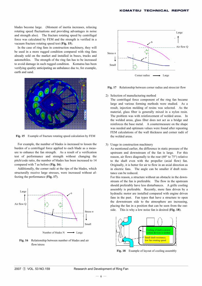
Fig. 17 Relationship between corner radius and stress/air flow
2) Selection of manufacturing method The centrifugal force component of the ring fan became
large and various forming methods were studied. As a result, injection molding of resins was selected. As the material, glass fiber is generally mixed in a nylon resin. The problem was with reinforcement of welded areas. In the welded areas, glass fiber does not act as a bridge and reinforces the base metal. A countermeasure on the shape was needed and optimum values were found after repeating FEM calculations of the wall thickness and corner radii of the welded areas.
3) Usage in construction machinery As mentioned earlier, the difference in static pressure of the
upstream and downstream of the fan is large. For this reason, air flows diagonally to the rear (60° to 75°) relative to the shaft even with the propeller (axial flow) fan. Originally, it is better for air to flow in an axial direction as in electric fans. The angle can be smaller if draft resis-tance can be reduced.
For this reason, a structure without an obstacle in the down-stream of the fan is preferable. The flow in the upstream should preferably have less disturbances. A grille cooling assembly is preferable. Recently, more fans driven by a hydraulic motor are installed compared with engine driven fans in the past. Fan types that have a structure to open the downstream side to the atmosphere are increasing, placing the fan in a position that can be seen from the out-side. This is why a low noise fan is desired (Fig. 18).
Large
Air flow Q
Stress σ
Small
Cooling of motive power system devices is neededNumber of blades N Large
Small draft resistance, low fan rotating speed
Fig. 18 Example of layout of cooling assembly
2007 ① VOL. 53 NO.159 Research and Development of Ring Fan
― 6 ―
4) Results of bench measurement and actual machines The ring fan was installed in a wind tunnel bench illus-
trated in Fig. 19. The performances of a conventional fan and the ring fan are compared in Fig. 20. Compared with a conventional fan, the ring fan improves noise by 4dB(A) at the same air flow.
Fig. 19 Schematics of wind tunnel bench
Fig. 20 Comparison of bench performances of conventional fan and the ring fan
Next, noise performances of a conventional fan and the ring fan equipped on a wheel loader and bulldozer are plotted in Figs. 21 and 22.
Fig. 21 Ambient dynamic noise of wheel loader
HI noise at the operator’s station of bulldozer Conventional fan
Ring fan Upstream resistance
Exhaust port
Rad
iato
r
Downstream resistance
Fan Entire bulldozer
Other than fan Equipment
Fig. 22 HI operator ear noise of bulldozer
The results of actual machines do not correspond to the
bench test results. This can be explained by the fact that im-pacts by parts around the fan are not taken into account in the bench tests and only noise and air flow of the fan itself (cool-ing assembly was installed) were measured. In the actual machines, a fan guard, hydraulic equipment, hoses, piping and other parts were installed as peripheral parts, which must have produced some impacts.
Conventional fan and the ring fan Conv. fan, small resistance (dia. 650) Conv. fan, large resistance (dia. 650)
Ring fan, small resistance (dia. 620) Ring fan, large resistance (dia. 620)
Conventional fan
Noi
se d
BA
Results of a frequency analysis in actual machines are plot-ted in Fig. 23. Large
resistance Small
resistance Not only fan NZ noise that was prominently reduced, but also broadband frequency noise were confirmed reduced.
Ring fan
Air flow Q (m3/sec)
Results of 6-point average frequency analysis Conventional fan Ring fan
Pow
er le
vel d
B(A
)
Fan NZ primary
Combustion primary (Not related to fan)
Ambient dynamic noise of wheel loader
1/3oct. Center frequency Hz Conventional fan
Fig. 23 Dynamic frequency analysis in actual machines
Ring fan
Fan Entire wheel loader
Other than fan Equipment
2007 ① VOL. 53 NO.159 Research and Development of Ring Fan
― 7 ―
5. Future Plan This development program was undertaken jointly with
T.RAD Co., Ltd. (formerly Toyo Radiator Co., Ltd.). The development of the fan itself was mainly undertaken by T.RAD Co., while Komatsu mainly developed equipping of the fan including actual machine usage.
Our honest feeling is that a ring fan, which is already sold on the market, for use in construction machinery has finally and viably been developed after surmounting barriers such as low noise, restrictions peculiar to construction machinery, cost and strength, after studying how this ring fan can be adopted in construction machinery.
We plan to modify the fan shape to achieve a higher effi-ciency and to expand the product family to further utilize the technology gained so far. References: 1) Chisachi Kato, et al., Tokyo University Production Research,
Vol. 54, No. 1-2, Serial No. 624, pp66-70 (Jan. 2002). 2) Shimada, K., “Advanced Design of Radiator Cooling Fan for
Automobiles,” pp.79, 105 (2004).
Introduction of the writer
Haruhiro Tsubota Entered Komatsu in 1979. Currently assigned to Construction Equip-ment Innovation Center 2, Research Divi-sion.
[A few words from the writer] In the past several years, my hobby has been swimming and I
swim thinking how best I can swim a long distance easily, the angles of my hands when I throw them into water and what types of foams do I make around my hands while swimming the crawl.
How the balls of table tennis, golf and baseball behave and how flying disc stably moves are interesting to watch when we become aware of the existence of a fluid.
My conclusion is that a smooth flow of a fluid reduces eddies generated, producing efficient work with smaller losses.
The work related to a fluid and noise is difficult because fluids and noise are not visible. I feel everyday that work becomes very interesting by “visualizing” things.
2007 ① VOL. 53 NO.159 Research and Development of Ring Fan


![Fan Guards 25mm - 52mm (1” - 2”) · OA80 Matching Fan Series: OD9220, OD9225, OA92, OA938. Part No.: G109-15A and G109-15AB [Black finish] Material: C1008 Steel Wire Dia (Ring):](https://static.documents.pub/doc/80x56/5f9f9ea68f1abe70e932e7b5/fan-guards-25mm-52mm-1a-2a-oa80-matching-fan-series-od9220-od9225-oa92.jpg)


