A broadband dual circularly polarized magnetoelectric dipole antenna (MEDA) fed by a miniaturized six-branch hybrid coupler(SBHC) is presented in this paper. First, a dual linearly polarized MEDA with a bandwidth of 73.3% is developed based on theprevious design with a bandwidth of 52%. The SBHC, with a miniaturized size of 53%, is designed on a printed circuit boardunderneath the ground of the MEDA, which possesses an efficient bandwidth of 80.7% to generate the antenna for dual circularpolarization. Measurement results show that the proposed dual circularly polarized MEDA achieves an impedance bandwidth of84.5%, an axial-ratio bandwidth of 81.8%, and a nearly symmetrical, stable unidirectional radiation pattern with an average gain of8 dBic over its impedance bandwidth.
1. Introduction
Circularly polarized (CP) antennas have significance inmod-ern wireless communications, such as satellite communica-tion, global positioning system (GPS), radar system, radiofrequency identification (RFID), wireless local area network(WLAN), and long term evolution (LTE), due to the flexibilitywithout polarization mismatch, multipath fading, and fara-day rotation effect. Dual CP antennas can realize both righthand circular polarization and left hand circular polarization,and thus they are valuable for the miniaturized systemswith frequency reuse or polarization diversity. Broadbandantennas represent the challenging issues for high-capacitycommunication, high-speed data-rate communication, orinteroperating several systems within the same module.Therefore, broadband dual CP antennas are valuable andpromising for the increasing requirements of wireless com-munications. In addition, the antennas with unidirectional,symmetrical, and stable radiation patterns are advantageousfor such systems due to the high coverage efficiency.
Broadband dual CP antennas can be transformed fromconventional broadband CP antennas. With reference tospiral antennas, many configurations have been designed fordual circular polarization at the expense of degraded array
efficiency due to a halved effective use of space [1, 2], sacrific-ing gain by the resister load [3], and complex, bulky feedingnetworks [4, 5]. Helix is another traditional broadband CPantenna and dual circular polarization can be generatedthrough two ports in both ends, but orthogonal polarizationoperates at separate bands [6]. A dual CP slot antennaachieved a 3-dB axial-ratio (AR) bandwidth of approximately60%, within which return loss and isolation were better than10 dB and 15 dB, respectively, but with bidirectional radiation[7]. Patch antennas are generally narrow band radiators,few of which are developed to realize broadband dual CPantennas. A dual CP patch generated by cross slots via atransmission line underneath the ground plane attained a 3-dB AR bandwidth of 48% and a 15-dB return loss bandwidthof 60%, at the cost of low isolation and gain [8]. Hybridcoupler is a popular scheme applied to patch antennasfor wideband dual circular polarization. Nevertheless, thebandwidth of normal hybrid couplers is still limited. On theother hand, broadband multibranch hybrid couplers occupya large area. Therefore, the hybrid couplers exceeding threebranches are rarely adopted in antennas for dual circularpolarization. A three-branch periodic hybrid coupler withan approximate 35% miniaturized size was designed togenerate a circular patch for dual circular polarization, which
Hindawi Publishing CorporationInternational Journal of Antennas and PropagationVolume 2016, Article ID 1385927, 10 pageshttp://dx.doi.org/10.1155/2016/1385927
2 International Journal of Antennas and Propagation
obtained an overall bandwidth of 14.7% [9]. Consequently, itis necessary to develop a novel configuration rather than atraditional antenna for excellent performances of broadbanddual circular polarization.
Magnetoelectric dipole antennas (MEDAs) with broad-band and symmetrical, stable unidirectional radiation pat-terns have been widely investigated and some designs forcircular polarization have been reported recently. A MEDAformed by two bowtie patch antennas and two electric dipolesachieved an impedance bandwidth of 41% and a 3-dB ARbandwidth of 33% [10]. A crossed dipole loaded with amagnetoelectric dipole can exhibit an impedance bandwidthof 60% and a 3-dB AR bandwidth of 27% [11]. An antennacomposed of two cross-placed magnetoelectric dipoles and afeeding network comprising a wideband 90∘ Schiffman phaseshifter achieved a 10-dB return loss bandwidth of 85.7% and a3-dB AR bandwidth of 61.5% [12]. AMEDA fed by a single Γ-shaped probe attained an impedance bandwidth of 73.3% anda 3-dB AR bandwidth of 47.7% [13]. A dual linearly polarized(LP) MEDA, excited by a power divider and a broadband 90∘phase shifter, obtained an impedance bandwidth of 90% anda 3-dBARbandwidth of 82% [14]. A 60GHz aperture coupledMEDA fed by a transverse slot etched on the broad wallof a section of shorted-end substrate integrated waveguide(SIW) showed an impedance bandwidth of 28.8% and a 3-dBAR bandwidth of 25.9% [15]. However, these MEDA designsmentioned above are all based on single circular polarization.
In this paper, a broadband dual CP MEDA is proposedfor the first time.The antenna is realized by a dual LPMEDAexcited through a 3-dB six-branch hybrid coupler (SBHC)with a 53% miniaturized size, which achieves an impedancebandwidth of 84.5% and a 3-dB AR bandwidth of 81.8%.Additionally, the antenna possesses a nearly symmetrical,stable unidirectional radiation pattern with an average gainof 8 dBic across its impedance bandwidth. The remainder ofthis paper is organized as follows. Section 2 explains the basicdesign of the presented antenna. In Section 3, a prototypeis fabricated and the performances are verified based on theexperiment. Finally, the conclusion is given in Section 4.
2. Broadband Dual CP MEDA Design
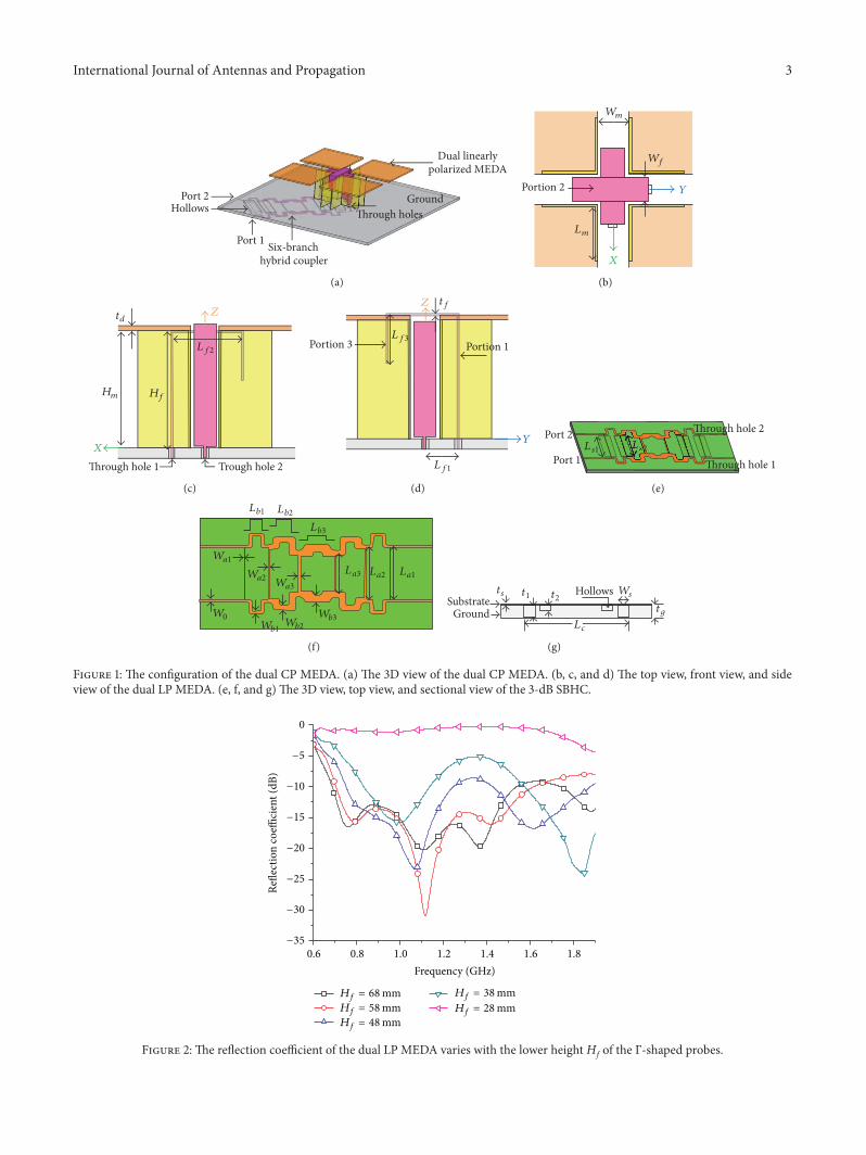
The configuration of the dual CP MEDA is illustrated inFigure 1, which is composed of a dual LP MEDA and aminiaturized 3-dB SBHC. The SBHC is located below theground of the dual LP MEDA, and the two output ports ofthe SBHC are connected to the Γ-shaped probes through theholes on the ground.
Figures 1(b), 1(c), and 1(d) show the configuration ofthe dual LP MEDA, which is constructed by four horizon-tally oriented square metallic plates, four vertically orientedshorted patches, two orthogonal Γ-shaped probes, and asquare ground.The four square metallic plates, with the sameside length Ld and thickness td, are shorted to the groundthrough the vertical walls of the four shorted patches, withthe length Lm, the width Wm, and the height Hm. Both themetallic plates and shorted patches are located uniformly,and they perform as crossed electric and magnetic dipoles
[14]. The two Γ-shaped probes are placed orthogonally in thegaps of the shorted patches. Each Γ-shaped probe, made byfolding a straight metallic strip of rectangular cross-sectioninto a Γ-shape, consists of three portions, namely, portion1, portion 2, and portion 3, the corresponding function ofwhich can be found in [16]. Compared to the dual LP MEDAintroduced in [14], the antenna has three improvements onthe Γ-shaped probes and ground, to broaden its bandwidthand make its structure symmetrical for broadband dualcircular polarization. First, portion 2 of the Γ-shaped probesis placed parallel to the horizontally oriented metallic platesto introduce another resonance frequency for a broaderimpedance bandwidth, which will be detailed later. Second,the Γ-shaped probes are symmetrical with the exception ofthe lengths of portion 1, which have a slight difference equalto td. Nevertheless, the Γ-shaped probes in the previousdesign have different values in all dimensions, and fivemore variations are required. As a result, the antenna withsymmetrical structure is more suitable to construct dualCP MEDA and has fewer variations for rapid optimization.Third, the four surrounding walls of the ground are removed,by which the antenna will have a lower quality factor and awider bandwidth than the previous design.
Figures 1(e), 1(f), and 1(g) demonstrate the microstripcircuit of the miniaturized 3-dB SBHC, which consists ofa thick ground, hollows, and microstrip lines from thebottom-up.The ground with thickness tg is located below thesubstrate.The rectangular hollows are placed underneath thestubs required high characteristic impedance in the SBHCdesign, with depths 𝑡1 and 𝑡2, lengths 𝐿 𝑠1 and 𝐿 𝑠2 , and thesame width Ws. The depths of the hollows are less than thethickness of the ground to reduce radiation losses. The mainlines are all constructed by folded lines, with lengths of Lbn(𝑛 = 1–3) and widths of Wbn (𝑛 = 1–3). By folding mainlines, the total length of the whole SBHC can be shortened toLc. The four ports of the SBHC are microstrip lines of 50Ω,with a width of𝑊0. The substrate has a permittivity of 2.55,loss tangent of 0.0018, and thickness of 0.762mm.
2.1. Dual LP MEDA Design Concept and Parametric Study.MEDAs are more suitable for base stations, and the operatingfrequencies of the second-generation (2G), 3G, LTE mobilecommunications and handsets fall into the 0.698–2.65GHzfrequency band [17]. The dual LP MEDA is designed tooperate at the lower band. The antenna is investigatedand optimized by CST microwave studio software, and theoptimal parameters are listed in Table 1. Owning to the nearlysymmetrical structure, only the antenna excited through theΓ-shaped probe with the lower height ofHf is investigated forbrevity.
To demonstrate the effect of paralleling the Γ-shapedprobes to the horizontally oriented metallic plates, thereflection coefficient of the dual LP MEDA varying withthe lower height Hf of the Γ-shaped probes is illustratedin Figure 2, while the other parameters remain constant.It can be observed that the antenna has three resonancefrequencies at approximately 0.75GHz, 1.1 GHz, and 1.4GHz,whenHf =Hm = 68mm, with the Γ-shaped probes parallel to
International Journal of Antennas and Propagation 3
Port 1
Port 2
Six-branch hybrid coupler
Ground
Dual linearly polarized MEDA
Through holesHollows
(a)
Portion 2
X
Y
Wm
Lm
Wf
(b)
Through hole 1 Trough hole 2X
Z
Hm
Lf2
Hf
td
(c)
Portion 3 Portion 1
Y
Z
Lf3
Lf1
tf
(d)
Port 2
Through hole 1Port 1
Through hole 2Ls1 Ls2
(e)
La1La2La3
Wa1
Wa2Wa3
Lb1 Lb2
Lb3
Wb1Wb2
Wb3W0
(f)
GroundSubstrate
Hollows Ws
tg
t1 t2ts
Lc
(g)
Figure 1: The configuration of the dual CP MEDA. (a) The 3D view of the dual CP MEDA. (b, c, and d) The top view, front view, and sideview of the dual LP MEDA. (e, f, and g) The 3D view, top view, and sectional view of the 3-dB SBHC.
0
−5
−10
−15
−20
−25
−30
−35
Refle
ctio
n co
effici
ent (
dB)
0.6 0.8 1.0 1.2 1.4 1.6 1.8
Frequency (GHz)
Hf = 68 mmHf = 58 mmHf = 48 mm
Hf = 38 mmHf = 28 mm
Figure 2: The reflection coefficient of the dual LP MEDA varies with the lower height Hf of the Γ-shaped probes.
4 International Journal of Antennas and Propagation
t = 0
t = T/4
(a)
t = 0
t = T/4
X
Y
(b)
t = 0
t = T/4
(c)
Figure 3:The current distribution of the dual LPMEDAexcited through the Γ-shaped probewith the lower height ofHf at the three resonancefrequencies. (a) 0.75GHz. (b) 1.1 GHz. (c) 1.4 GHz.
Table 1: Optimized parameters of the dual CP MEDA.
Parameters of the dual LP MEDAParameters 𝐿𝑑 𝐿𝑚 𝐿𝑓1 𝐿𝑓2 𝐿𝑓3 𝐿𝑔 𝑊𝑚
the metallic plates. However, when Hf is decreased to valueslower than the height Hm of the metallic plates in decre-ment of 10mm, the impedance bandwidth of the antennais gradually narrowed. The lower resonance frequency atapproximately 0.75GHz disappears and the higher resonancefrequency at approximately 1.4 GHz shifts past 1.6 GHz, whenHf is less than 48mm. As a result, the antenna becomes
the design given in [14], which has only two resonance fre-quencies and a narrower impedance bandwidth.The antennaachieves a simulated impedance bandwidth of 73.3% for thereflection coefficient less than−10 dB, covering the band from0.68GHz to 1.54GHz, whereas the previous design obtains abandwidth of 52% for the SWR less than 2.
To better understand the performances of the dual LPMEDA, the current distribution and important parametersincluding the side length Ld of the metallic plates and theheight Hm of the shorted patches are analyzed by CST. Theother parameters in Table 1 remain unchanged, while eachindividual parameter is varied.
Figure 3 displays the current distribution of the dual LPMEDA excited through the Γ-shaped probe with the lowerheight ofHf at the three resonance frequencies. At the centrefrequency of 1.1 GHz, the antenna operates as a perfect mag-netoelectric dipole, with the magnetic and electric dipolesof nearly the same amplitude and a 90∘ phase difference.However, the antenna works at a hybrid mode of electricand magnetic dipoles at the lower resonance frequency of0.75GHz, with the magnetic dipole excited at time t = 0 andboth the magnetic and electric dipoles generated at time t =T/4 (T is a period of time).This phenomenon also appears atthe higher resonance frequency of 1.4GHz, and highermodesare also generated at this frequency. Fortunately, the hybrid
International Journal of Antennas and Propagation 5
5
0
−5
−10
−15
−20
−25
−30Re
flect
ion
coeffi
cien
t (dB
)
0.6 0.8 1.0 1.2 1.4 1.6
2
4
6
8
10
Frequency (GHz)
Gai
n (d
Bic)
Ld = 69 mmLd = 72 mm
Ld = 75 mm
Figure 4: The reflection coefficient and gain of the dual LP MEDA vary with the side length L𝑑 of the metallic plates.
5
0
−5
−10
−15
−20
−25
−30
Refle
ctio
n co
effici
ent (
dB)
0.6 0.8 1.0 1.2 1.4 1.6
Frequency (GHz)
2
4
6
8
10
Gai
n (d
Bic)
Hm = 65 mmHm = 68 mm
Hm = 71 mm
Figure 5: The reflection coefficient and gain of the dual LP MEDA vary with the height H𝑚 of the shorted patches.
mode of electric and magnetic dipoles still dominates at1.4 GHz.
Figure 4 shows that the reflection coefficient and gainof the antenna vary with the side length Ld of the metallicplates. Across the frequency band from 0.6GHz to 1.6GHz,all the three resonance frequencies shift down as Ld becomeslonger. It can be observed that the reflection coefficient atthe higher band is sensitive to Ld, because both the electricdipole and higher modes of the antenna are influenced by thelength.Moreover, the gain reduces at the higher bandwhileLdincreases, which is primarily caused by the increasing highermodes. Considering the reflection coefficient, gain, and theassociated efficient bandwidth, Ld = 72mm is the optimalchoice.
Figure 5 shows that the reflection coefficient and gain ofthe antenna vary with the height Hm of the shorted patches,while keeping portion 2 of the Γ-shaped probes parallel tothe metallic plates. The impedance bandwidth has limitedchange when Hm varies from 65mm to 68mm but narrowssignificantly while Hm approaches 71mm. The gain also
reduces at the higher band while Hm increases, but the rangeof change is smaller than that from varying the side length Ldof the metallic plates. Considering the reflection coefficient,gain, and the associated bandwidth, Hm = 68mm is selected.
The investigations above are summarized as follows. Theimpedance matching at the lower band can be broadenedby paralleling the Γ-shaped probes to the metallic plates tointroduce another resonance frequency.The impedance at thehigher band is primarily determined by the side length Ld ofthe metallic plates.The gain at the higher band rapidly drops,primarily due to the increasing higher modes generated onthe metallic plates. It can be observed that the gain at thelower band slowly reduces, which is caused by the hybridmode of the magnetic and electric dipoles with an imperfectcombination [18].
2.2. Miniaturized 3-dB SBHC Design and Performances.Multibranch hybrid coupler is a conventional method torealize broadband hybrid coupler. The circuit model for
6 International Journal of Antennas and Propagation
1 2
34
b1 b2 bn−1
a1 a2
g
O1
O2
an−1 an
Zo = 50
Figure 6: The circuit model of the multibranch hybrid coupler.
(d)Figure 7: The S parameter of the 3-dB SBHC. (a) The 𝑆11 and 𝑆22. (b) The amplitude of 𝑆21 and 𝑆31 and the amplitude difference betweenthem. (c) The phase difference between 𝑆21 and 𝑆31. (d) The isolation between the two ports.
multibranch hybrid coupler is illustrated in Figure 6 [19].The impedance of the stubs is donated by 𝑎1, 𝑎2, . . . , 𝑎𝑛 andthe main line impedance by 𝑏1, 𝑏2, . . . , 𝑏𝑛. The lengths ofeach stub and main line are 𝜆g/4 (𝜆g corresponds to thetransmission line guide wavelength). Based on the synthesismethod presented in [19], a symmetrical 3-dB SBHC isdesigned for the feeding circuit of the dual CPMEDA, and thetheoretical characteristic impedance of the stubs and mainlines is listed in Table 2.
In principle, the multibranch hybrid coupler can bedesigned on various types of transmission lines, whereas theone designed on printed circuit board (PCB) has become
Table 2: The theoretical characteristic impedance of the stubs andmain lines of the 3-dB SBHC (unit: Ω).
𝑎1 𝑎2 𝑎3 𝑏1 𝑏2 𝑏3
𝑍0 = 50 (Ω) 254 177 98 40 32 28
main stream due to the advantages of low profile, simplefabrication, and low cost. In Table 2, it can be found thatthe maximum characteristic impedance of the stubs is 254Ω,approximately 9 times theminimumof 28Ω of themain lines.Realizing high characteristic impedance is the most difficult
International Journal of Antennas and Propagation 7
(b)Figure 8: The pictures and S parameter of the dual CP MEDA. (a) The pictures of the dual CP MEDA and 3-dB SBHC. (b) The S parameterof the dual CP MEDA.
problem of themultibranch hybrid coupler designed on PCB.For high characteristic impedance, the ratio of the microstripline width to the thickness of the substrate is required tobe sufficiently small. The ultimate limit for normal PCBfabrication is 0.2mm and the thickness of the substrate is alsolimited, which leads to the highest characteristic impedancerealized by traditional PCB that is approximately 130Ω [20].In this design, the rectangular hollows are placed underneaththe stubs which required high characteristic impedance, toobtain the sufficiently small ratio of the microstrip line widthto the thickness of the equivalent substrate.
Based on the theoretical characteristic impedance inTable 2, the SBHC is designed and optimized by CST, andthe optimal parameters are listed in Table 1. The final lengthof the SBHC is 132mm, whereas the total length withoutfolded lines is 250mm. As a result, the presented SBHCgains a miniaturized size of 53% through folding main lines.Moreover, with this method, the stubs with different widthsWan (𝑛 = 1–3) can have different lengths of Lan (𝑛 = 1–3)to achieve the identical electrical length of 𝜆g/4. Therefore,improved performances of the SBHC can be achieved withfolded lines.
The SBHC was fabricated and measured according tothe parameters in Table 1 and the picture is shown inFigure 8(a). The simulated and measured S parameter isshown in Figure 7. In Figure 7(a), the measured commonreflection coefficient bandwidth of the two ports is 88.4%across the band from 0.6GHz to 1.55GHz for both 𝑆11 and𝑆22 less than −10 dB and covers the impedance bandwidthof the dual LP MEDA. Figure 7(b) shows the amplitude of
𝑆21 and 𝑆31. The measured amplitude difference between 𝑆21and 𝑆31 is less than 2.2 dB during the band from 0.65GHz to1.53GHz. Figure 7(c) shows the phase difference between 𝑆21and 𝑆31, which is within 84∘–93.7∘ from 0.6GHz to 1.53GHz.In Figure 7(d), the measured isolation of 𝑆41 is higher than11.6 dB during the observation band from0.6GHz to 1.6GHz.Consequently, the SBHC obtains an efficient bandwidth of80.7% from 0.65GHz to 1.53GHz. The measured insertionloss of the SBHC is less than 0.68 dB over the efficientbandwidth. It should be noted that the emphases of thesynthesis method and optimization adopted in this designare for the widest bandwidth and the minimum amplitudedifference between 𝑆21 and 𝑆31 over the band, at the expenseof the relatively lower isolation. The measured results havesome divergences compared to the simulations, which arecaused by fabrication errors, assembly errors, and inaccuracyin determining the permittivity of the substrate.
3. Results
The dual CP MEDA was fabricated and measured based onthe parameters in Table 1. The pictures of the dual CPMEDAand 3-dB SBHC are shown in Figure 8(a). The simulationandmeasurement results including the S parameter, radiationpattern, gain, and AR are compared and discussed.
Figure 8(b) depicts the S parameter of the dual CPMEDA. The measured reflection coefficient bandwidth ofport 1 for 𝑆11 less than −10 dB is 88% within the bandfrom 0.6GHz to 1.57GHz, and the one of port 2 for 𝑆22
8 International Journal of Antennas and Propagation
Figure 9: The normalized radiation patterns of the dual CP MEDA at the frequencies of 0.7 GHz, 1 GHz, 1.3 GHz, and 1.5 GHz.
less than −10 dB is 84.5% across the band from 0.6GHz to1.53GHz. The measured isolation of 𝑆21 between the twoports is greater than 6.6 dB during the observation band.The low isolation between the two ports is primarily due totwo reasons. First, the isolation of the SBHC is only higherthan 11.6 dB across the band. Second, the input impedanceof the Γ-shaped probes is not exactly equal to 50Ω as theload of the SBHC, which will deteriorate the isolation. Thesimulated and measured results are well matched, except ata few frequencies. With reference to the requirements of abroadband antenna, those deviations are acceptable.
Figure 9 depicts the normalized radiation patterns ofthe dual CP MEDA in phi = 0∘ and phi = 90∘ planes atthe frequencies of 0.7GHz, 1 GHz, 1.3 GHz, and 1.5 GHz.
The radiation patterns with a 3-dB beamwidth of approxi-mately 65∘ remain nearly symmetrical and stable across theband except at 1.5 GHz, where slight deterioration occurs inboth planes due to the higher modes. It can be observedthat both the worst back radiation and cross-polarization areapproximately −10 dB at the lowest and highest frequency of0.7 GHz and 1.5 GHz, respectively. The higher back radiationat 0.7GHz is due to two reasons. First, the magnetic andelectric dipoles with an imperfect combination form thehybridmode [18]. Second, the ground has an electrical lengththat is only 0.63 𝜆o (𝜆o corresponds to the wavelength inair) at this frequency. At 1.5 GHz, the higher back radiationis caused by the spurious radiation from the SBHC belowthe ground. The lower cross-polarization at 0.7 GHz and
International Journal of Antennas and Propagation 9
0.6 0.8 1.0 1.2 1.4 1.6
Frequency (GHz)
10
9
8
7
6
5
4
3
7
6
5
4
3
2
1
0
Gai
n (d
Bic)
Simulated gainMeasured gain
Simulated axial-ratioMeasured axial-ratio
Axi
al-r
atio
(dB)
Figure 10: The gain and axial-ratio (AR) of the dual CP MEDA.
1.5 GHz is due to the imperfect feeding from the 3-dBSBHC. The measured results are well matched with thesimulations.
Figure 10 shows the gain and AR at the zenith of thedual CP MEDA. The gain is higher than 6 dBic and has anaverage value of 8 dBicwithin the impedance bandwidth from0.6GHz to 1.53GHz.The gain reaches a maximum of 9.1 dBicat 1.3 GHz and drops down when the frequency shifts past1.3 GHz. That is due to the radiation pattern deterioratingwhile the frequency exceeds 1.3 GHz. The measured gainat some frequencies is lower than the simulation results,which is attributed to the losses not considered in thesimulation. The measured 3-dB AR bandwidth at the zenithis 81.8% across the band from 0.63GHz to 1.53GHz. Themeasured AR diverges simulation results over the band,which is due to the processing, assembly, and measurementerrors.
4. Conclusion
In this work, a broadband dual CP MEDA is realized by adual LP MEDA excited through a miniaturized 3-dB SBHC,which achieves an impedance bandwidth of 84.5% and a3-dB AR bandwidth of 81.8%. By paralleling the Γ-shapedprobes with the metallic plates, the bandwidth of the dualLP MEDA broadens largely through introducing anotherresonance frequency. The imperfect feeding from the 3-dBSBHC deteriorates the cross-polarization of the antenna,which can be reduced by changing the square metallic platesto rectangular plates for fine-tuning. In addition, themethodsto achieve high characteristic impedance andminiaturizationadopted in the design of the SBHC can be used in otherdesigns of multibranch hybrid couplers.
Competing Interests
The authors declare that there are no competing interestsregarding the publication of this paper.
Acknowledgments
This work was supported by the National Natural Sci-ence Foundation (61201058, 61471240), the Research andInnovation Project of Shanghai Education Commission(12Z112030001), and the Scientific Research Foundation forReturned Overseas Chinese Scholars, State Education Min-istry, and the Project of “SMC Excellent Young Faculty.”
References
[1] I. D. Hinostroza Saenz, R. Guinvarc’h, R. L. Haupt, and K.Louertani, “A dual-polarized wideband planar phased arraywith spiral antennas,” IEEE Transactions on Antennas andPropagation, vol. 62, no. 9, pp. 4547–4553, 2014.
[2] M. Serhir andR.Guinvarc’H, “A low-profile cavity-backed dual-polarized spiral antenna array,” IEEE Antennas and WirelessPropagation Letters, vol. 12, pp. 524–527, 2013.
[3] H.-T. Chou, P.-H. Hsueh, and L.-R. Kuo, “Two-arm spiralantenna array with dual circular polarised radiations for multi-beam applications at Ku-band,” Electronics Letters, vol. 48, no.21, pp. 1322–1323, 2012.
[4] A.Mehrabani and L. Shafai, “Compact dual circularly polarizedprimary feeds for symmetric parabolic reflector antennas,” IEEEAntennas andWireless Propagation Letters, vol. 15, pp. 922–925,2016.
[5] H. R. Fang, M. Serhir, R. Guinvarc’h, and K. Mouthaan,“Enhanced dual-circular polarised four-arm Archimedean spi-ral antenna with low-profile cavity backing,” IET Microwaves,Antennas and Propagation, vol. 9, no. 12, pp. 1260–1266, 2015.
[6] Y. B. Jung, S. Y. Eom, S. I. Jeon, and S. O. Park, “Dual-band and dual-polarised horn antenna including conical helix,”Electronics Letters, vol. 43, no. 8, pp. 432–434, 2007.
[7] R. K. Saini and S. Dwari, “A broadband dual circularly polarizedsquare slot antenna,” IEEE Transactions on Antennas andPropagation, vol. 64, no. 1, pp. 290–294, 2016.
[8] E. Aloni and R. Kastner, “Analysis of a dual circularly polarizedmicrostrip antenna fed by crossed slots,” IEEE Transactions onAntennas and Propagation, vol. 42, no. 8, pp. 1053–1058, 1994.
[9] A. Garcıa-Aguilar, J.-M. Inclan-Alonso, L. Vigil-Herrero, J.-M.Fernandez-Gonzalez, and M. Sierra-Perez, “Low-profile dualcircularly polarized antenna array for satellite communicationsin the X band,” IEEE Transactions on Antennas and Propagation,vol. 60, no. 5, pp. 2276–2284, 2012.
[10] K. M. Mak and K. M. Luk, “A circularly polarized antenna withwide axial ratio beamwidth,” IEEE Transactions on Antennasand Propagation, vol. 57, no. 10, pp. 3309–3312, 2009.
[11] S. X. Ta and I. Park, “Crossed dipole loaded with magneto-electric dipole for wideband and wide-beam circularly polar-ized radiation,” IEEEAntennas andWireless Propagation Letters,vol. 14, pp. 358–361, 2015.
[12] W. Liang, Y.-C. Jiao, J. Li, and T. Ni, “Circularly polarisedmagneto-electric dipole antenna,”Electronics Letters, vol. 50, no.14, pp. 976–978, 2014.
[13] M. Li and K.-M. Luk, “A wideband circularly polarized antennafor microwave and millimeter-wave applications,” IEEE Trans-actions on Antennas and Propagation, vol. 62, no. 4, pp. 1872–1879, 2014.
10 International Journal of Antennas and Propagation
[14] M. Li and K.-M. Luk, “Wideband magnetoelectric dipoleantennaswith dual polarization and circular polarization,” IEEEAntennas and Propagation Magazine, vol. 57, no. 1, pp. 110–119,2015.
[15] Y. Li and K.-M. Luk, “A 60-GHz wideband circularly polarizedaperture-coupled magneto-electric dipole antenna array,” IEEETransactions on Antennas and Propagation, vol. 64, no. 4, pp.1325–1333, 2016.
[16] K.-M. Luk and H. Wong, “A new wideband unidirectionalantenna element,” International Journal of Microwave and Opti-cal Technology, vol. 1, no. 1, pp. 35–44, 2006.
[17] K.-M. Luk and B. Wu, “The magnetoelectric dipole—a wide-band antenna for base stations in mobile communications,”Proceedings of the IEEE, vol. 100, no. 7, pp. 2297–2307, 2012.
[18] D.-H.Kwon, “On the radiationQand the gain of crossed electricandmagnetic dipole moments,” IEEE Transactions on Antennasand Propagation, vol. 53, no. 5, pp. 1681–1687, 2005.
[19] R. Levy and L. F. Lind, “Synthesis of symmetrical branch-guidedirectional couplers,” IEEE Transactions on Microwave Theoryand Techniques, vol. 16, no. 2, pp. 80–89, 1968.
[20] C.-W. Tang, M.-G. Chen, Y.-S. Lin, and J.-W. Wu, “Broadbandmicrostrip branch-line coupler with defected ground structure,”IEEE Electronic Letters, vol. 42, no. 25, pp. 1458–1460, 2006.


![Design of a Broadband Circularly Polarized Antenna ArrayIn [5], the circularly polarized square-slot antenna array designed by using sequential rotation feed structure can achieve](https://static.documents.pub/doc/80x56/60b437807a304623c120e529/design-of-a-broadband-circularly-polarized-antenna-in-5-the-circularly-polarized.jpg)


