Research ArticleClosed Loop Direct Adaptive Inverse Control for Linear Plants
Muhammad Amir Shafiq1 Muhammad Shafiq2 and Nisar Ahmed1
1 Faculty of Electronics Engineering GIKI Topi Pakistan2 Sultan Qaboos University Muscat Oman
Correspondence should be addressed to Muhammad Amir Shafiq amirshafiqgmailcom
Received 4 August 2013 Accepted 27 October 2013 Published 19 January 2014
Academic Editors S Berretti and D K Iakovidis
Copyright copy 2014 Muhammad Amir Shafiq et al This is an open access article distributed under the Creative CommonsAttribution License which permits unrestricted use distribution and reproduction in any medium provided the original work isproperly cited
In direct adaptive inverse control (DAIC) parameters of the controller are estimated directly in the feed-forward loop In thispaper we propose a closed loop direct adaptive inverse control (CDAIC) scheme which improves tracking error convergenceand disturbance rejection properties of DAIC CDAIC is applicable to stable or stabilized minimum or nonminimum phase linearplants CDAIC andDAIC are compared using computer simulations for disturbance free and disturbed discrete type nonminimumphase linear plants CDAIC shows better results compared to DAIC in terms of mean square tracking error and disturbancerejection
1 Introduction
Adaptive control over the last five decades has emergedas one of the well-established discipline see Astrom andWittenmark [1] Gang andRogelio [2] and Sastry andBodson[3] In adaptive inverse control (AIC) parameters of theinverse are obtained using direct or direct methods refer toWidrow and Walach [4] Widrow and Bilello [5] Widrowand Plett [6] Plett [7] Shafiq [8] and M Shafiq and M AShafiq [9] AIC has attracted the interest of many researchersfor many years due to its computationally less expensive androbust tracking characteristics see Widrow and Walach [4]Widrow and Bilello [5] and Yin et al [10] Majority of AICschemes are developed for stable or stabilized plant and havebeen applied successfully to numerous practical problemssuch as temperature control of a heating process speedcontrol of a dc motor control of kiln control of nonlinearshipmaneuvering real time blood pressure control andnoisecancelation see Shafiq [8] Dias and Mota [11] Du et al [12]and Widrow and Walach [4] All physical systems in the realworld are inherently nonlinear in nature but we linearizethose plants around certain point and range to obtain linearbehavior If plant is unstable then it is assumed that it wasstabilized using any known control law before applying AICscheme refer to Widrow and Walach [4] and Ogata [13] In
this paper we will discuss tracking schemes for discrete timestable or stabilized linear plants only
Discrete type plants for which one or more zeros lieoutside the unit circle are called nonminimum phase plantssee [14] Nonminimum phase plant poses some controllerdesign problems such as extra phase lag step response innegative direction because their inverse is unstable refer toOgata [13] Numerous techniques have been developed forcontrol of minimum and nonminimum phase plants referto Widrow and Walach [4] Widrow and Bilello [5] Widrowand Plett [6] Plett [7] Shafiq [8] M Shafiq and M AShafiq [9] Bai and Dasgupta [15] and Wang and Chen [16]In DAIC schemes inverse is designed based on identifiedplant see Plett [7] and Shafiq et al [9] DAIC alleviatesthe adhocism in adaptive loop by directly estimating theinverse of the plant in feed-forward loop Adaptive inversecontrol of linear and nonlinear systems using dynamic neuralnetworks is presented in Plett [7] In Plett [7] controller isdesigned based on identified plant Similarly DAIC schemebased on identification of the nonlinear autoregressive modelwith exogenous inputs (NARX) is presented in Yin et al[10] Direct and indirect model based control for nonlinearsingle input single output (SISO) plant using artificial neuralnetworks are discussed in Wang and Chen [16] DAIC basedon neural network has also been successfully applied for
Hindawi Publishing Corporatione Scientific World JournalVolume 2014 Article ID 658497 8 pageshttpdxdoiorg1011552014658497
2 The Scientific World Journal
controlling kiln see Dias and Mota [11] In this paperwe propose a closed loop direct adaptive inverse controltechnique based on normalized least mean square (NLMS)for controlling linear plants CDAIC can be used for trackingof stable or stabilized minimum or nonminimum phaselinear plants
The rest of this paper is organized as follows Section 2presents problem statement Details of the DAIC schemeare given in Section 3 Design of proposed scheme (CDAIC)is discussed in Section 4 Simulation results are given inSection 5 and finally conclusion is given in Section 6
2 Problem Statement
Let us consider 119875(119902minus1) is a discrete time stable or stabilizedlinear plant Let 119875(119902minus1) be given by
119875 (119902minus1
) = 119902minus119889
119861 (119902minus1
)
119860 (119902minus1)
119860 (119902minus1
) = 1 + 1198861
119902minus1
+ 1198862
119902minus2
+ sdot sdot sdot + 119886119899
119902minus119899
119861 (119902minus1
) = 1198870
+ 1198871
119902minus1
+ 1198872
119902minus2
+ sdot sdot sdot + 119887119898
119902minus119898
(1)
where 119902minus1 is a back shift operator defined as 119902minus1119910(119896) =
119910(119896 minus 1) 119896 is positive integer that represents time instantand 119889 is a positive integer it represents delay of the plantWe assume that 119899 and 119898 are unknown positive integers and119899 ge 119898119860(119902minus1) and 119861(119902minus1) are relatively coprime polynomialsWe also assume that plant may be nonminimum phase thatis inverse of plant is unstable Let 119903(119896) 119910
119889
(119896) and 119910(119896)
be the reference input desired output and plant outputrespectively Further it is assumed that parameters of theplant are unknown or slowly time varying compared to theadaptation algorithm The objective is to design a controllersuch that 119910(119896) tracks 119910
119889
(119896) that is
lim119896rarrinfin
(119890ref (119896))2
= lim119896rarrinfin
(119910119889
(119896) minus 119910 (119896))2
= 120598 (2)
where 119910119889
(119896) = 119903(119896 minus 119871) 119871 is a positive integer that representsknown delay 119890ref (119896) is error at instant 119896 and 120598 is arbitrarilysmall positive real number in neighborhood of zero
3 Direct Adaptive Inverse Control
DAIC scheme for controlling discrete time linear plantsproposed in M Shafiq and M A Shafiq [9] is shown inFigure 1 In DAIC approximate inverse system 119876
119871
(119902minus1
) isdirectly estimated in feed-forward loop and control input119906(119896) is synthesized using
119906 (119896) = 119876119871
(119902minus1
) 119903 (119896) (3)
In DAIC first of all an approximate model of plant (119902minus1)is estimated Then 119890
119891
(119896) is obtained by back-propagatingreference error 119890ref (119896) through estimated plant model (119902minus1)Finally 119890
119891
(119896) is used to adapt the weights of adaptive
r(k)
ef(k)
P(qminus1)
P(qminus1)
P(qminus1)(q
minus1)
y(k)u(k)
y(k)minus
minus
+
+
emod (k)
eref (k)
yd(k)
qminusL
QL
Σ
Figure 1 Direct adaptive inverse control
r(k)
ef(k)
P(qminus1)
P(qminus1)
P(qminus1) F(q
minus1)(q
minus1)
y(k)u(k)
y(k) minus
+
minus
minus
+
+
emod (k)
eref (k)
yd(k)qminusL
QL
Σ
Σ
ΣGf(qminus1) 120575
Figure 2 Closed loop direct adaptive inverse control
inverse controller NLMS is used to estimate weights of plantmodel (119902minus1) and adaptive inverse controller119876
119871
(119902minus1
)Weightupdate equation for controller is given by
120579 (119896 + 1)
=
120579 (119896) if 120595 (119896) 120595119879 (119896) = 0
where 120579(119896) is parameter vector for119876119871
(119902minus1
) 1205831
is learning rateand 0 le 120583
1
le 1 120595(119896) is regression vector defined as
120595 (119896) = [119903 (119896) 119903 (119896 minus 1) 119903 (119896 minus 119873)] (5)
where 119873 + 1 are number of controller parameters DAICalleviates the adhocism of adaptive loop by directly estimat-ing the controller in feed-forward loop Since plant model isidentified first DAIC is less sensitive to plant uncertaintiesand variations DAIC depend on perfect estimation of plantmodel Any nonlinearities or error in estimating correct plantmodel could degrade the performance of DAIC
4 Design of CDAIC
We propose CDAIC structure shown in Figure 2 To the bestof our survey CDAIC scheme depicted in Figure 2 has notbeen reported in the literature In this structure feedback isused to improve the performance of DAIC That is why we
call it CDAIC Control input to plant is synthesized such thatplant tracks the desired input 119910
119889
(119896) Control input 119906(119896) isgiven by
119906 (119896) = 119876119871
(119902minus1
) (Γ (119902) 119903 (119896) minus 120575119910 (119896)) (6)
where 119910(119896) is the feedback from the plant Γ(119902) is FIRfilter given by Γ(119902) = 1 + 120575119902
minus(119897+119889) 119897 is a positive integerand 120575 is any positive real number such that 0 lt 120575 lt
1 120575 also makes sure that control input remains boundedfor bounded input and system does not become unstableSteady state error is minimized using negative feedbackMean square error (MSE) between desired output and plant
output for nonminimum phase plants can be made smallby incorporating the delay 119902
minus119871 119876119871
(119902minus1
) is used as feed-forward controller for 119875(119902minus1) Since plant and its inverse arein cascade they collectively form a transfer function whichsatisfies
119902minus(119897+119889)
119876119871
(119902minus1
) 119875 (119902minus1
) 119865 (119902minus1
) asymp 119902minus119871
(7)
Proof We assume that 119876119871
(119902minus1
) is an approximate inverse of119875(119902minus1
)119865(119902minus1
) that is
119876119871
(119902minus1
) 119875 (119902minus1
) 119865 (119902minus1
) asymp 119902minus(119897+119889)
(8)
4 The Scientific World Journal
0
1
2
3
4
5
6
7
8
9A
mpl
itude
Mean square error
0 2 4 6 8 10 12 14 16 18 20Time
CDAICDAIC
(a)
0 2 4 6 8 10 12 14 16 18 20minus04
minus02
0
02
04
06
08
1
12
Time
Am
plitu
de
Control input
CDAICDAIC
(b)
minus12
minus1
minus08
minus06
minus04
minus02
0
02
04
Am
plitu
de
Model identification error
0 2 4 6 8 10 12 14 16 18 20Time
CDAICDAIC
(c)
Figure 4 Example 1 simulation results (a) mean square error (b) control input (c) model identification error
therefore transfer function of inner closed loop is obtained as
119866119894
(119902minus1
) asymp120575119902minus(119897+119889)
1 + 120575119902minus(119897+119889) (9)
It is clear that minus1 lt 120575 lt 1 assures the stability of closed loopThe filter 119866
119891
(119902minus1
) = (1 + 120575119902minus(119897+119889)
)120575 is incorporated in serieswith 119866
119894
(119902minus1
) Now the overall closed loop transfer function119866119888
(119902minus1
) is given by
119866119888
(119902minus1
) = 119866119891
(119902minus1
) sdot 119866119894
(119902minus1
)
asymp1 + 120575119902
minus(119897+119889)
120575sdot
120575119902minus(119897+119889)
1 + 120575119902minus(119897+119889)
= 119902minus(119897+119889)
asymp 119902minus119871
(10)
Remarks 1 Choosing 0 lt 120575 lt 1 makes 119866119894
(119902minus1
) a fastlow pass filter This property filters out the noise from theadaptive loop which insures smooth estimation of 119876
119871
(119902minus1
)
parameters
Remarks 2 Main cause of oscillations in the parameters ofthe adaptive inverse controller is the noisy plant signal Thelow pass filter behavior of the inner closed loop reducesoscillations in the parameter estimation and ultimately theplant output becomes smoothThe overall closed loop systembecomes less sensitive to abrupt changes which enhance therobustness in the signal tracking
Remarks 3 Small positive values of 120575 reduces the open loopgainThis property improves the robustness in the closed loopstability
where 120596(119896) is parameter vector for CDAIC controller119876119871
(119902minus1
) 1205832
is learning rate and 0 le 1205832
le 1 120593(119896) is regressionvector defined as
120593 (119896) = [V (119896) V (119896 minus 1) V (119896 minus 119873)] (14)
6 The Scientific World Journal
minus18
minus16
minus14
minus12
minus10
minus8
minus6
minus4
minus2
0
2
Am
plitu
deTracking error
0 2 4 6 8 10 12 14 16 18 20Time
CDAICDAIC
(a)
0
20
40
60
80
100
120
140
160
180
200
Am
plitu
de
Mean square error
0 2 4 6 8 10 12 14 16 18 20Time
CDAICDAIC
(b)
Figure 6 Example 2 simulation results (a) tracking error (b) mean square error
where119873+ 1 are number of controller parameters and V(119896) isgiven by
V (119896) = Γ (119902) 119903 (119896) minus 120575119910 (119896) (15)
5 Simulation Results
Computer simulations of CDAIC and DAIC scheme arepresented to show effectiveness of CDAIC Two linear non-minimumphase systems are chosen onewithout disturbanceand other with disturbance
Example 1 A disturbance free discrete time nonminimumphase linear plant is chosen having
This is a stable nonminimum phase plant having zeros atminus12500 plusmn 11990119894 poles at 04516 plusmn 06519119894 and minus05016 plusmn
04749119894 In this example the learning rate of both CDAICand DAIC is chosen as 0001 for controller and 001 for plantAlso 120575 is chosen as 01 for CDIAC Order of 119876
119871
(119902minus1
) for bothCDAIC andDAIC is chosen as 10 Sampling time is chosen as0001 sec Simulation results are depicted in Figures 3 and 4
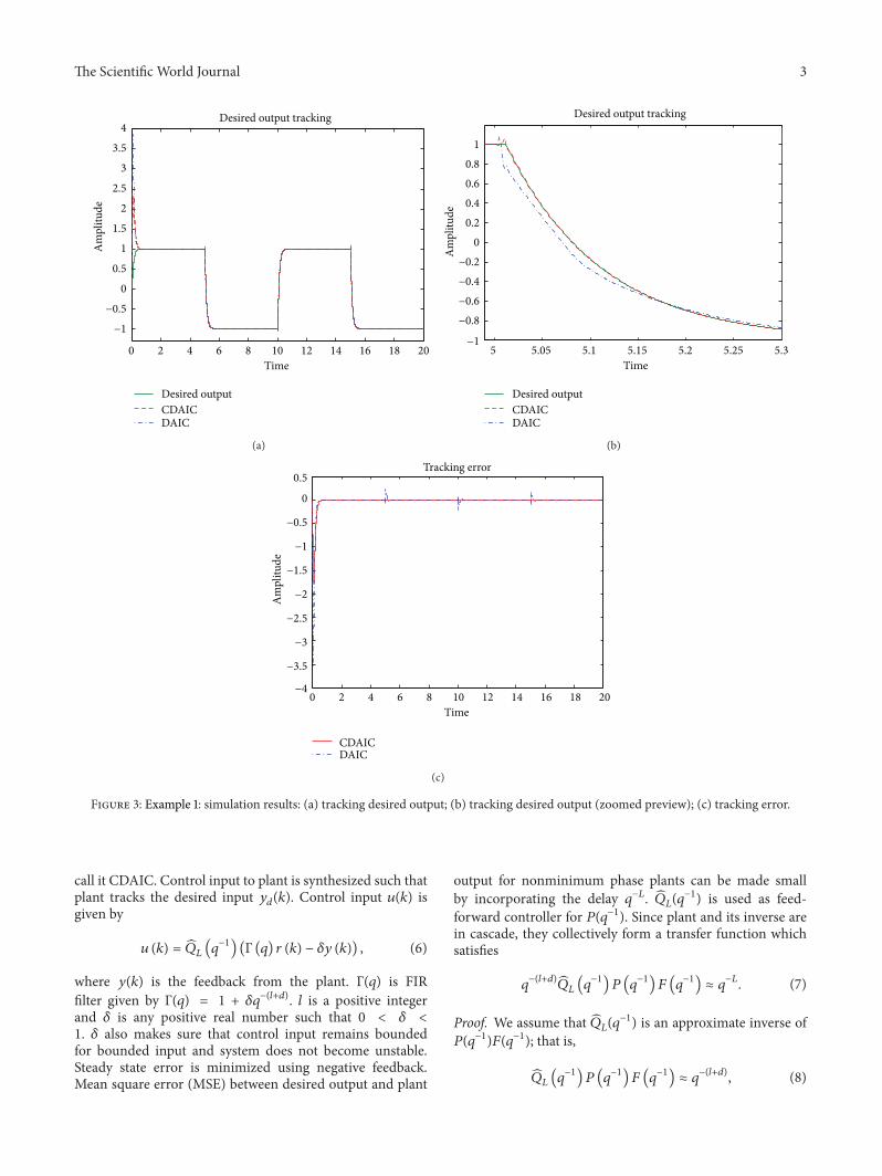
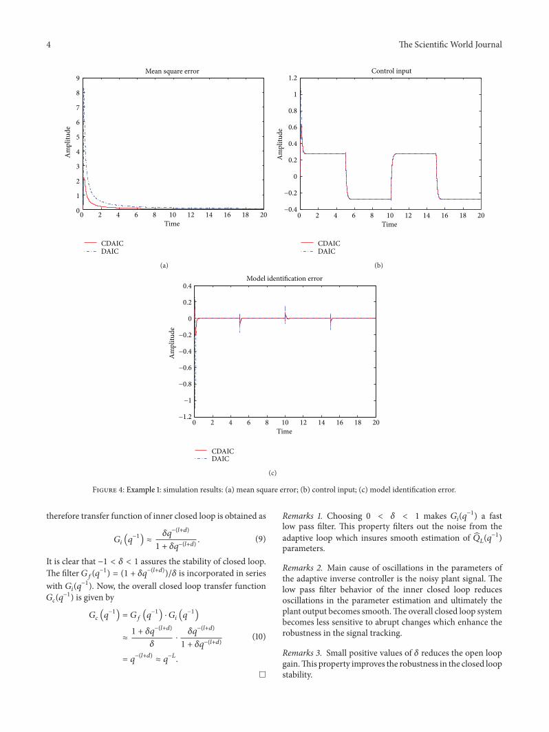
Desired output tracking is shown in Figures 3(a) and 3(b)Plant output in CDAIC has less overshoot and converges todesired output quickly compared to DAIC Tracking error isshown in Figure 3(c) Tracking error has less amplitude andconverges to zero faster in CDAIC compared to DAIC AlsoCDAIC has low error at variations in desired output such as atinstant 5 sec and 10 sec MSE for CDAIC and DAIC is shownin Figure 4(a) MSE is less for CDAIC compared to DAIC
Control input is also shown in Figure 4(b) Control input inCDAIC is synthesized such that it converges faster and givesbetter tracking compared toDAICModel identification error119890 mod (119896) is also shown in Figure 4(c) Model identificationerror in CDAIC converges quickly to zero compared to DAICeven for same leaning rate of plant model approximation
Example 2 A disturbance 119899(119896) is added to discrete timenonminimum phase linear plant Plant output can now bewritten as
This is a stable nonminimum phase plant having zeros atminus25 plusmn 13229119894 poles at minus07650 plusmn 05470119894 and 05150 plusmn
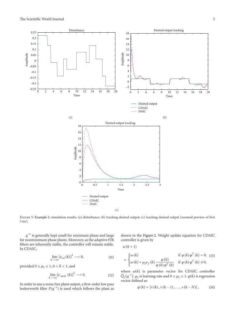
07254119894 In this example the learning rate of both CDAIC andDAIC is chosen as 00001 for controller and 0001 for plantAlso 120575 is chosen as 002 for CDIAC Sampling time is chosenas 0001 sec Simulation results are shown in Figures 5 and 7
119899(119896) disturbance added to the plant is shown inFigure 5(a) Desired output tracking is shown in Figures 5(b)and 5(c) As shown in Figure 5(c) plant output in CDAIC hasless overshoot and converges to desired output quickly com-pared to DAIC Tracking error is low for CDAIC comparedto DAIC as shown in Figure 6(a) Mean square tracking errorof CDAIC is less than DAIC and is depicted in Figure 6(b)Control input andmodel identification error for both CDAICand DAIC are shown in Figures 7(a) and 7(b) respectively
The Scientific World Journal 7
minus05
0
05
1
15
2
25
3
35
Am
plitu
deControl input
0 2 4 6 8 10 12 14 16 18 20Time
CDAICDAIC
(a)
minus3
minus2
minus1
0
1
2
3
Am
plitu
de
Model identification error
0 2 4 6 8 10 12 14 16 18 20Time
CDAICDAIC
(b)
Figure 7 Example 2 simulation results (a) control input (b) model identification error
Control input in CDAIC is synthesized such that it not onlygives better tracking as compared to DAIC but also has gooddisturbance rejection properties
6 Conclusion
A closed loop direct controller based on NLMS for adaptivetracking of stable plants is proposed CDAIC is applicable toboth minimum and nonminimum phase discrete time linearplants NLMS algorithm is used for estimation of plant andcontroller in conjunction with FIR filter at the input stageNegative feedback has improved the tracking and disturbancerejection properties of DAIC Simulation results show thatCDAIC performs better than DAIC in terms of trackingand mean square error Little modification can also establishmodel reference adaptive control (MRAC)
Conflict of Interests
The authors declare that there is no conflict of interestsregarding the publication of this paper
Acknowledgements
The authors would like to thanks Mr Adam Khan andGhulam Ishaq Khan Institute of Engineering Sciences andTechnology for their help and support
References
[1] K J Astrom and B Wittenmark Adaptive Control Addison-Wesley Longman Boston Mass USA 1994
[2] F Gang and L RogelioAdaptive Control Systems Elsevier 1999
[3] S Sastry and M Bodson Adaptive Control Stability Conver-gence and Robustness Prentice-Hall 1989
[4] B Widrow and E Walach Adaptive Inverse Control A SignalProcessing Approach Prentice Hall 1995
[5] B Widrow and M Bilello ldquoAdaptive inverse controlrdquo in Pro-ceedings of the IEEE International Symposium on IntelligentControl pp 1ndash6 Chicago Ill USA August 1993
[6] B Widrow and G L Plett ldquoAdaptive inverse control based onlinear and nonlinear adaptive filteringrdquo in Proceedings of the 1stInternational Workshop on Neural Networks for IdentificationControl Robotics and SignalImage Processing (NICROSP rsquo96)pp 30ndash38 Venice Italy August 1996
[7] G L Plett ldquoAdaptive inverse control of linear and nonlinearsystems using dynamic neural networksrdquo IEEE Transactions onNeural Networks vol 14 no 2 pp 360ndash376 2003
[8] M Shafiq ldquoInternal model control structure using adaptiveinverse control strategyrdquo ISA Transactions vol 44 no 3 pp353ndash362 2005
[9] M Shafiq and M A Shafiq ldquoDirect adaptive inverse controlrdquoIEICE Electronics Express vol 6 no 5 pp 223ndash229 2009
[10] J Yin F Dong and N Wang ldquoDirect adaptive inverse controlbased on variable radial basis function networkrdquo in Proceedingsof the 6thWorld Congress on Intelligent Control and Automation(WCICA rsquo06) pp 2709ndash2712 June 2006
[11] F M Dias and A M Mota ldquoDirect inverse control of a kilnrdquoin Proceedings of the 4th Portuguese Conference on AutomaticControl Guimares Portugal 2000
[12] G Du X Zhan W Zhang and S Zhong ldquoImproved filtered-120576adaptive inverse control and its application on nonlinear shipmaneuveringrdquo Journal of Systems Engineering and Electronicsvol 17 no 4 pp 788ndash792 2006
[13] K Ogata Modern Control System Prentice Hall Upper SaddleRiver NJ USA 4th edition 2001
[14] 2010 httpenwikipediaorgwikiNonminimum phase[15] E-W Bai and S Dasgupta ldquoMinimal k-step delay controller for
robust tracking of non-minimumphase systemsrdquo inProceedings
8 The Scientific World Journal
of the 33rd IEEE Conference on Decision and Control pp 12ndash17December 1994
[16] XWang andD Chen ldquoCausal inversion of nonminimumphasesystemsrdquo in Proceedings of the 40th IEEE Conference on Decisionand Control (CDC) pp 73ndash78 December 2001
controlling kiln see Dias and Mota [11] In this paperwe propose a closed loop direct adaptive inverse controltechnique based on normalized least mean square (NLMS)for controlling linear plants CDAIC can be used for trackingof stable or stabilized minimum or nonminimum phaselinear plants
The rest of this paper is organized as follows Section 2presents problem statement Details of the DAIC schemeare given in Section 3 Design of proposed scheme (CDAIC)is discussed in Section 4 Simulation results are given inSection 5 and finally conclusion is given in Section 6
2 Problem Statement
Let us consider 119875(119902minus1) is a discrete time stable or stabilizedlinear plant Let 119875(119902minus1) be given by
119875 (119902minus1
) = 119902minus119889
119861 (119902minus1
)
119860 (119902minus1)
119860 (119902minus1
) = 1 + 1198861
119902minus1
+ 1198862
119902minus2
+ sdot sdot sdot + 119886119899
119902minus119899
119861 (119902minus1
) = 1198870
+ 1198871
119902minus1
+ 1198872
119902minus2
+ sdot sdot sdot + 119887119898
119902minus119898
(1)
where 119902minus1 is a back shift operator defined as 119902minus1119910(119896) =
119910(119896 minus 1) 119896 is positive integer that represents time instantand 119889 is a positive integer it represents delay of the plantWe assume that 119899 and 119898 are unknown positive integers and119899 ge 119898119860(119902minus1) and 119861(119902minus1) are relatively coprime polynomialsWe also assume that plant may be nonminimum phase thatis inverse of plant is unstable Let 119903(119896) 119910
119889
(119896) and 119910(119896)
be the reference input desired output and plant outputrespectively Further it is assumed that parameters of theplant are unknown or slowly time varying compared to theadaptation algorithm The objective is to design a controllersuch that 119910(119896) tracks 119910
119889
(119896) that is
lim119896rarrinfin
(119890ref (119896))2
= lim119896rarrinfin
(119910119889
(119896) minus 119910 (119896))2
= 120598 (2)
where 119910119889
(119896) = 119903(119896 minus 119871) 119871 is a positive integer that representsknown delay 119890ref (119896) is error at instant 119896 and 120598 is arbitrarilysmall positive real number in neighborhood of zero
3 Direct Adaptive Inverse Control
DAIC scheme for controlling discrete time linear plantsproposed in M Shafiq and M A Shafiq [9] is shown inFigure 1 In DAIC approximate inverse system 119876
119871
(119902minus1
) isdirectly estimated in feed-forward loop and control input119906(119896) is synthesized using
119906 (119896) = 119876119871
(119902minus1
) 119903 (119896) (3)
In DAIC first of all an approximate model of plant (119902minus1)is estimated Then 119890
119891
(119896) is obtained by back-propagatingreference error 119890ref (119896) through estimated plant model (119902minus1)Finally 119890
119891
(119896) is used to adapt the weights of adaptive
r(k)
ef(k)
P(qminus1)
P(qminus1)
P(qminus1)(q
minus1)
y(k)u(k)
y(k)minus
minus
+
+
emod (k)
eref (k)
yd(k)
qminusL
QL
Σ
Figure 1 Direct adaptive inverse control
r(k)
ef(k)
P(qminus1)
P(qminus1)
P(qminus1) F(q
minus1)(q
minus1)
y(k)u(k)
y(k) minus
+
minus
minus
+
+
emod (k)
eref (k)
yd(k)qminusL
QL
Σ
Σ
ΣGf(qminus1) 120575
Figure 2 Closed loop direct adaptive inverse control
inverse controller NLMS is used to estimate weights of plantmodel (119902minus1) and adaptive inverse controller119876
119871
(119902minus1
)Weightupdate equation for controller is given by
120579 (119896 + 1)
=
120579 (119896) if 120595 (119896) 120595119879 (119896) = 0
where 120579(119896) is parameter vector for119876119871
(119902minus1
) 1205831
is learning rateand 0 le 120583
1
le 1 120595(119896) is regression vector defined as
120595 (119896) = [119903 (119896) 119903 (119896 minus 1) 119903 (119896 minus 119873)] (5)
where 119873 + 1 are number of controller parameters DAICalleviates the adhocism of adaptive loop by directly estimat-ing the controller in feed-forward loop Since plant model isidentified first DAIC is less sensitive to plant uncertaintiesand variations DAIC depend on perfect estimation of plantmodel Any nonlinearities or error in estimating correct plantmodel could degrade the performance of DAIC
4 Design of CDAIC
We propose CDAIC structure shown in Figure 2 To the bestof our survey CDAIC scheme depicted in Figure 2 has notbeen reported in the literature In this structure feedback isused to improve the performance of DAIC That is why we
call it CDAIC Control input to plant is synthesized such thatplant tracks the desired input 119910
119889
(119896) Control input 119906(119896) isgiven by
119906 (119896) = 119876119871
(119902minus1
) (Γ (119902) 119903 (119896) minus 120575119910 (119896)) (6)
where 119910(119896) is the feedback from the plant Γ(119902) is FIRfilter given by Γ(119902) = 1 + 120575119902
minus(119897+119889) 119897 is a positive integerand 120575 is any positive real number such that 0 lt 120575 lt
1 120575 also makes sure that control input remains boundedfor bounded input and system does not become unstableSteady state error is minimized using negative feedbackMean square error (MSE) between desired output and plant
output for nonminimum phase plants can be made smallby incorporating the delay 119902
minus119871 119876119871
(119902minus1
) is used as feed-forward controller for 119875(119902minus1) Since plant and its inverse arein cascade they collectively form a transfer function whichsatisfies
119902minus(119897+119889)
119876119871
(119902minus1
) 119875 (119902minus1
) 119865 (119902minus1
) asymp 119902minus119871
(7)
Proof We assume that 119876119871
(119902minus1
) is an approximate inverse of119875(119902minus1
)119865(119902minus1
) that is
119876119871
(119902minus1
) 119875 (119902minus1
) 119865 (119902minus1
) asymp 119902minus(119897+119889)
(8)
4 The Scientific World Journal
0
1
2
3
4
5
6
7
8
9A
mpl
itude
Mean square error
0 2 4 6 8 10 12 14 16 18 20Time
CDAICDAIC
(a)
0 2 4 6 8 10 12 14 16 18 20minus04
minus02
0
02
04
06
08
1
12
Time
Am
plitu
de
Control input
CDAICDAIC
(b)
minus12
minus1
minus08
minus06
minus04
minus02
0
02
04
Am
plitu
de
Model identification error
0 2 4 6 8 10 12 14 16 18 20Time
CDAICDAIC
(c)
Figure 4 Example 1 simulation results (a) mean square error (b) control input (c) model identification error
therefore transfer function of inner closed loop is obtained as
119866119894
(119902minus1
) asymp120575119902minus(119897+119889)
1 + 120575119902minus(119897+119889) (9)
It is clear that minus1 lt 120575 lt 1 assures the stability of closed loopThe filter 119866
119891
(119902minus1
) = (1 + 120575119902minus(119897+119889)
)120575 is incorporated in serieswith 119866
119894
(119902minus1
) Now the overall closed loop transfer function119866119888
(119902minus1
) is given by
119866119888
(119902minus1
) = 119866119891
(119902minus1
) sdot 119866119894
(119902minus1
)
asymp1 + 120575119902
minus(119897+119889)
120575sdot
120575119902minus(119897+119889)
1 + 120575119902minus(119897+119889)
= 119902minus(119897+119889)
asymp 119902minus119871
(10)
Remarks 1 Choosing 0 lt 120575 lt 1 makes 119866119894
(119902minus1
) a fastlow pass filter This property filters out the noise from theadaptive loop which insures smooth estimation of 119876
119871
(119902minus1
)
parameters
Remarks 2 Main cause of oscillations in the parameters ofthe adaptive inverse controller is the noisy plant signal Thelow pass filter behavior of the inner closed loop reducesoscillations in the parameter estimation and ultimately theplant output becomes smoothThe overall closed loop systembecomes less sensitive to abrupt changes which enhance therobustness in the signal tracking
Remarks 3 Small positive values of 120575 reduces the open loopgainThis property improves the robustness in the closed loopstability
where 120596(119896) is parameter vector for CDAIC controller119876119871
(119902minus1
) 1205832
is learning rate and 0 le 1205832
le 1 120593(119896) is regressionvector defined as
120593 (119896) = [V (119896) V (119896 minus 1) V (119896 minus 119873)] (14)
6 The Scientific World Journal
minus18
minus16
minus14
minus12
minus10
minus8
minus6
minus4
minus2
0
2
Am
plitu
deTracking error
0 2 4 6 8 10 12 14 16 18 20Time
CDAICDAIC
(a)
0
20
40
60
80
100
120
140
160
180
200
Am
plitu
de
Mean square error
0 2 4 6 8 10 12 14 16 18 20Time
CDAICDAIC
(b)
Figure 6 Example 2 simulation results (a) tracking error (b) mean square error
where119873+ 1 are number of controller parameters and V(119896) isgiven by
V (119896) = Γ (119902) 119903 (119896) minus 120575119910 (119896) (15)
5 Simulation Results
Computer simulations of CDAIC and DAIC scheme arepresented to show effectiveness of CDAIC Two linear non-minimumphase systems are chosen onewithout disturbanceand other with disturbance
Example 1 A disturbance free discrete time nonminimumphase linear plant is chosen having
This is a stable nonminimum phase plant having zeros atminus12500 plusmn 11990119894 poles at 04516 plusmn 06519119894 and minus05016 plusmn
04749119894 In this example the learning rate of both CDAICand DAIC is chosen as 0001 for controller and 001 for plantAlso 120575 is chosen as 01 for CDIAC Order of 119876
119871
(119902minus1
) for bothCDAIC andDAIC is chosen as 10 Sampling time is chosen as0001 sec Simulation results are depicted in Figures 3 and 4
Desired output tracking is shown in Figures 3(a) and 3(b)Plant output in CDAIC has less overshoot and converges todesired output quickly compared to DAIC Tracking error isshown in Figure 3(c) Tracking error has less amplitude andconverges to zero faster in CDAIC compared to DAIC AlsoCDAIC has low error at variations in desired output such as atinstant 5 sec and 10 sec MSE for CDAIC and DAIC is shownin Figure 4(a) MSE is less for CDAIC compared to DAIC
Control input is also shown in Figure 4(b) Control input inCDAIC is synthesized such that it converges faster and givesbetter tracking compared toDAICModel identification error119890 mod (119896) is also shown in Figure 4(c) Model identificationerror in CDAIC converges quickly to zero compared to DAICeven for same leaning rate of plant model approximation
Example 2 A disturbance 119899(119896) is added to discrete timenonminimum phase linear plant Plant output can now bewritten as
This is a stable nonminimum phase plant having zeros atminus25 plusmn 13229119894 poles at minus07650 plusmn 05470119894 and 05150 plusmn
07254119894 In this example the learning rate of both CDAIC andDAIC is chosen as 00001 for controller and 0001 for plantAlso 120575 is chosen as 002 for CDIAC Sampling time is chosenas 0001 sec Simulation results are shown in Figures 5 and 7
119899(119896) disturbance added to the plant is shown inFigure 5(a) Desired output tracking is shown in Figures 5(b)and 5(c) As shown in Figure 5(c) plant output in CDAIC hasless overshoot and converges to desired output quickly com-pared to DAIC Tracking error is low for CDAIC comparedto DAIC as shown in Figure 6(a) Mean square tracking errorof CDAIC is less than DAIC and is depicted in Figure 6(b)Control input andmodel identification error for both CDAICand DAIC are shown in Figures 7(a) and 7(b) respectively
The Scientific World Journal 7
minus05
0
05
1
15
2
25
3
35
Am
plitu
deControl input
0 2 4 6 8 10 12 14 16 18 20Time
CDAICDAIC
(a)
minus3
minus2
minus1
0
1
2
3
Am
plitu
de
Model identification error
0 2 4 6 8 10 12 14 16 18 20Time
CDAICDAIC
(b)
Figure 7 Example 2 simulation results (a) control input (b) model identification error
Control input in CDAIC is synthesized such that it not onlygives better tracking as compared to DAIC but also has gooddisturbance rejection properties
6 Conclusion
A closed loop direct controller based on NLMS for adaptivetracking of stable plants is proposed CDAIC is applicable toboth minimum and nonminimum phase discrete time linearplants NLMS algorithm is used for estimation of plant andcontroller in conjunction with FIR filter at the input stageNegative feedback has improved the tracking and disturbancerejection properties of DAIC Simulation results show thatCDAIC performs better than DAIC in terms of trackingand mean square error Little modification can also establishmodel reference adaptive control (MRAC)
Conflict of Interests
The authors declare that there is no conflict of interestsregarding the publication of this paper
Acknowledgements
The authors would like to thanks Mr Adam Khan andGhulam Ishaq Khan Institute of Engineering Sciences andTechnology for their help and support
References
[1] K J Astrom and B Wittenmark Adaptive Control Addison-Wesley Longman Boston Mass USA 1994
[2] F Gang and L RogelioAdaptive Control Systems Elsevier 1999
[3] S Sastry and M Bodson Adaptive Control Stability Conver-gence and Robustness Prentice-Hall 1989
[4] B Widrow and E Walach Adaptive Inverse Control A SignalProcessing Approach Prentice Hall 1995
[5] B Widrow and M Bilello ldquoAdaptive inverse controlrdquo in Pro-ceedings of the IEEE International Symposium on IntelligentControl pp 1ndash6 Chicago Ill USA August 1993
[6] B Widrow and G L Plett ldquoAdaptive inverse control based onlinear and nonlinear adaptive filteringrdquo in Proceedings of the 1stInternational Workshop on Neural Networks for IdentificationControl Robotics and SignalImage Processing (NICROSP rsquo96)pp 30ndash38 Venice Italy August 1996
[7] G L Plett ldquoAdaptive inverse control of linear and nonlinearsystems using dynamic neural networksrdquo IEEE Transactions onNeural Networks vol 14 no 2 pp 360ndash376 2003
[8] M Shafiq ldquoInternal model control structure using adaptiveinverse control strategyrdquo ISA Transactions vol 44 no 3 pp353ndash362 2005
[9] M Shafiq and M A Shafiq ldquoDirect adaptive inverse controlrdquoIEICE Electronics Express vol 6 no 5 pp 223ndash229 2009
[10] J Yin F Dong and N Wang ldquoDirect adaptive inverse controlbased on variable radial basis function networkrdquo in Proceedingsof the 6thWorld Congress on Intelligent Control and Automation(WCICA rsquo06) pp 2709ndash2712 June 2006
[11] F M Dias and A M Mota ldquoDirect inverse control of a kilnrdquoin Proceedings of the 4th Portuguese Conference on AutomaticControl Guimares Portugal 2000
[12] G Du X Zhan W Zhang and S Zhong ldquoImproved filtered-120576adaptive inverse control and its application on nonlinear shipmaneuveringrdquo Journal of Systems Engineering and Electronicsvol 17 no 4 pp 788ndash792 2006
[13] K Ogata Modern Control System Prentice Hall Upper SaddleRiver NJ USA 4th edition 2001
[14] 2010 httpenwikipediaorgwikiNonminimum phase[15] E-W Bai and S Dasgupta ldquoMinimal k-step delay controller for
robust tracking of non-minimumphase systemsrdquo inProceedings
8 The Scientific World Journal
of the 33rd IEEE Conference on Decision and Control pp 12ndash17December 1994
[16] XWang andD Chen ldquoCausal inversion of nonminimumphasesystemsrdquo in Proceedings of the 40th IEEE Conference on Decisionand Control (CDC) pp 73ndash78 December 2001
of the 33rd IEEE Conference on Decision and Control pp 12ndash17December 1994
[16] XWang andD Chen ldquoCausal inversion of nonminimumphasesystemsrdquo in Proceedings of the 40th IEEE Conference on Decisionand Control (CDC) pp 73ndash78 December 2001