Hindawi Publishing CorporationMathematical Problems in EngineeringVolume 2013, Article ID 890427, 9 pageshttp://dx.doi.org/10.1155/2013/890427
Research ArticleCooperative Control of Regenerative Braking andAntilock Braking for a Hybrid Electric Vehicle
Guodong Yin1,2 and XianJian Jin1
1 School of Mechanical Engineering, Southeast University, Nanjing 211189, China2 State Key Laboratory of Mechanical Transmission, Chongqing University, Chongqing 400044, China
Correspondence should be addressed to Guodong Yin; [email protected]
Received 10 August 2013; Revised 16 October 2013; Accepted 24 October 2013
A new cooperative braking control strategy (CBCS) is proposed for a parallel hybrid electric vehicle (HEV) with both a regenerativebraking system and an antilock braking system (ABS) to achieve improved braking performance and energy regeneration. Thebraking system of the vehicle is based on a new method of HEV braking torque distribution that makes the antilock brakingsystem work together with the regenerative braking system harmoniously. In the cooperative braking control strategy, a slidingmode controller (SMC) for ABS is designed to maintain the wheel slip within an optimal range by adjusting the hydraulic brakingtorque continuously; to reduce the chattering in SMC, a boundary-layer method with moderate tuning of a saturation function isalso investigated; based on the wheel slip ratio, battery state of charge (SOC), and the motor speed, a fuzzy logic control strategy(FLC) is applied to adjust the regenerative braking torque dynamically. In order to evaluate the performance of the cooperativebraking control strategy, the braking system model of a hybrid electric vehicle is built in MATLAB/SIMULINK. It is found fromthe simulation that the cooperative braking control strategy suggested in this paper provides satisfactory braking performance,passenger comfort, and high regenerative efficiency.
1. Introduction
In the hybrid electric vehicle, regenerative braking takes placeby transforming the mechanical energy into electric energyvia a generator, the electric energy is stored in the energystoring device such as battery or supercapacitor, and thestored energy is recycled to propel the vehicle via a motor.Energy regeneration during braking is an effective approachto improve vehicle efficiency, especially for vehicles in heavystop and go traffic [1–3].
Generally, in order to ensure appropriate braking perfor-mance and energy regeneration, most HEVs are equippedwith both an antilock braking system and a regenerativebraking system. As one of the most popular active systemsof vehicles, the antilock braking system (ABS) helps thedriver to maintain control of the vehicle during emergencybraking or braking on a slippery road by preventing wheellockup; it has dramatically improved vehicle stability duringbraking. The regenerative braking system works togetherwith the antilock braking system for the following reasons:
(a) the regenerative braking torque is not large enoughto cover the required braking torque; (b) the regenerativebraking cannot be used for many reasons such as a high stateof charge (SOC) or high temperature of the battery to increasethe battery life. In these cases, the antilock braking systemworks to supply the required braking torque. Therefore, thecooperative control strategy between the antilock brakingsystem and the regenerative braking system is an importantissue to research on HEV.
As for the cooperative control strategy, few investiga-tions have been reported. Present research mainly focuseson two different braking aspects. One is the regenerationefficiency of various types of regenerative braking systemsfor the electric vehicle (EV) and HEV [4, 5]. Wyczalksuggested a mathematical formulation for the regenerativebraking energy by considering the charging and dischargingefficiencies and showed that a significant improvement inthe regenerative braking could be achieved [6]. Yeo et al.proposed a regenerative braking algorithm with CVT ratiocontrol for a parallel HEV equipped with a CVT; the CVT
2 Mathematical Problems in Engineering
ratio is controlled to operate the motor on the most efficientregion during regenerative braking; the experiments showthat the regenerative braking algorithm offers an improvedbattery SOC [7]. The optimum control strategy was adoptedto improve the regeneration efficiency [8]. The other focusis the emergency braking process. Taking advantage of thequick response and accurate control of the motor torque,researchers worldwide have explored a way to introducethe motor torque into an antilock brake system (ABS)control, expecting a better control effect [9–11]. However,these strategies neglected the cooperative control between theconventional hydraulic braking system and the regenerativebraking system, and it is difficult to achieve good brakingstability and high regenerative braking efficiency simultane-ously. Pu et al. and Peng et al. suggested a combined controlalgorithm, a logic threshold control strategy to controlhydraulic braking torque and a fuzzy logic control strategy toadjust regenerative braking torque [12, 13]. Nevertheless, themagnitude of the regenerative torque varies also dependingon the vehicle velocity, and the problem of fluctuating vehiclevelocity (variablemotor input speeds) has not been addressedin the paper. Because of problems such as nonlinearityin the vehicle-braking dynamics and variations in modelparameters over awide range due to variations in road surfaceand vehicle conditions, conventional ABS controller cannotachieve satisfactory performance. However, sliding-modecontrol, which is insensitive to parameter variations andexternal disturbances and is applicable to nonlinear systems,has become widespread [14, 15]. Therefore, a sliding modecontroller (SMC) for ABS is designed; in order to reduce thechattering, a boundary-layer method with moderate tuningof a saturation function is also investigated. Based on thewheel slip ratio, battery state of charge (SOC), and the motorspeed, a fuzzy logic control strategy (FLC) is proposed in thispaper.
2. System Modeling
Simulation is a crucial step of research and developmentnowadays. In order to test and verify the cooperative brakingcontrol strategy and to evaluate the control effect, simulationis required. To carry out the simulation, appropriate modelsincluding those of the vehicle (overall dynamics), the tire,the electric motor, the battery, and the hydraulic system werebuilt.
2.1. Vehicle Dynamics. Since only a straight-line brakingmaneuver is considered, the vehicle model takes into accountonly longitudinal movement. For a straight-line brakingmotion, that is, the movement does not include lateral andvertical motions, and the effect of the slight vibration ofsuspension system, yaw movement can be neglected, asthe effect is very small. Therefore, a typical three degreesof freedom vehicle dynamic model, which possesses thefundamental characteristics of an actual system and sufficientaccuracy, is used in this paper. These 3-DOF include thelongitudinal velocity, the front-wheel angular speed, and therear-wheel angular speed of the vehicle. In the hybrid electricvehicle, the regenerative braking torque works often only on
the front axle of the vehicle; considering this and the normalforce transfers, bymaking use ofNewton’s second law and lawof rotation, the vehicle dynamic model is built; the dynamicequations are therefore derived as follows:
𝑚V = 𝐹𝑥− 𝐹𝑎− 𝐹𝑓
= 𝜇𝐹(𝜆) 𝐹𝑧𝐹+ 𝜇𝑅(𝜆) 𝐹𝑧𝑅− 𝐹𝑎− 𝑓𝑚𝑔,
(1)
𝐼𝜔��𝐹= 𝐹𝑥𝐹𝑅 − 𝑇ℎ𝐹− 𝑇𝑓𝐹
− 𝑇𝑚
= 𝜇𝐹(𝜆) 𝐹𝑧𝐹𝑅 − 𝑇ℎ𝐹− 𝑇𝑓𝐹
− 𝑇𝑚,
(2)
𝐼𝜔��𝑅= 𝐹𝑥𝑅𝑅 − 𝑇ℎ𝑅− 𝑇𝑓𝑅
= 𝜇𝑅(𝜆) 𝐹𝑧𝑅𝑅 − 𝑇ℎ𝑅− 𝑇𝑓𝑅,
(3)
𝐹𝑧𝐹=
𝑚𝑔
𝐿
(𝑙𝑅+
V
𝑔
ℎ𝑔) , (4)
𝐹𝑧𝑅
=
𝑚𝑔
𝐿
(𝑙𝐹−
V
𝑔
ℎ𝑔) , (5)
where 𝑚, V, 𝐹𝑥, 𝐹𝑎, 𝐹𝑓, and 𝑓 are the vehicle mass, the
longitudinal velocity of the vehicle, the longitudinal force, theair resistance, the rolling resistance, and the coefficient of therolling resistance, respectively; 𝐹
𝑧𝐹and 𝐹
𝑧𝑅are the front tire
normal force and the rear tire normal force, respectively. Also,𝜇𝐹(𝜆) and 𝜇
𝑅(𝜆) are the friction coefficients of the front and
rear tires, respectively, and will be described later ((6) and(7)); the friction coefficient is a nonlinear function of somephysical variables, including the velocity of the vehicle andwheel slip. 𝐼
𝜔, 𝐹𝑥𝐹, and 𝐹
𝑥𝑅are the inertia moment of the
wheel, the longitudinal tire force on the front wheel, and thelongitudinal tire force on the rear wheel, respectively; 𝑇
ℎ𝐹,
𝑇ℎ𝑅, 𝑇𝑓𝐹, 𝑇𝑓𝑅, and 𝑇
𝑚are the hydraulic braking torque on the
front wheel, the hydraulic braking torque on the rear wheel,the rolling resistance torque on the front wheel, the rollingresistance torque on the rear wheel, and the regenerativebraking torque on the front wheel, respectively; 𝑙
𝐹is the
distance from vehicle center of gravity to front axle centerline, 𝑙
𝑅is the distance from vehicle center of gravity to rear
axle center line, 𝐿 is the wheel base, and ℎ𝑔is the height of
the center of gravity.
2.2.The Tire. The tire model is a very essential part in vehiclesimulation research.ThePacejka nonlinear tiremodel “MagicFormula” is a widely used tire model in automotive industry,which possesses a high fitting accuracy andwas first proposedby Pacejka in 1991. In this paper, Pacejka’s nonlinear tiremodel “Magic Formula” is used. In the tire model of themathematical descriptions, a set of trigonometric formulasis used to describe the mathematical relation of the athleticparameters of tire.Themagic formula tire model is presentedby
𝜇𝑖(𝜆) = 𝜃𝐷 sin (𝐶 tan−1 {𝐵𝜆
𝑖− 𝐸 [𝐵𝜆
𝑖− tan−1 (𝐵𝜆
𝑖)]}) ,
(6)
𝜆𝑖=
V − 𝜔𝑖𝑅
V, (7)
Mathematical Problems in Engineering 3
0 0.2 0.4 0.6 0.8 10
0.2
0.4
0.6
0.8
1
Asphalt dry
Cobblestones wet
𝜇
𝜆
Figure 1: Slip and the friction coefficient relationship based onPacejka’s nonlinear tire model.
0100
200
02000
40006000
0.40.50.6
0.70.80.9
Motor torque (Nm)Motor speed (rpm)
Effici
ency
−100−200
Figure 2: Efficiency characteristics of the electric motor.
where the friction coefficient 𝜇 is related to the longitudinalslip ratio 𝜆, 𝑖 is the rear wheel or the front wheel, and 𝜃 isthe (maximum) TRFC which has been widely explored andestimated in recent decades. The meanings of the parameters𝐵, 𝐶, 𝐷, and 𝐸 can be easily found in the paper by Pacejkaand Bakker [16]. Tire models with both high 𝜇 and low 𝜇 areshown in Figure 1.
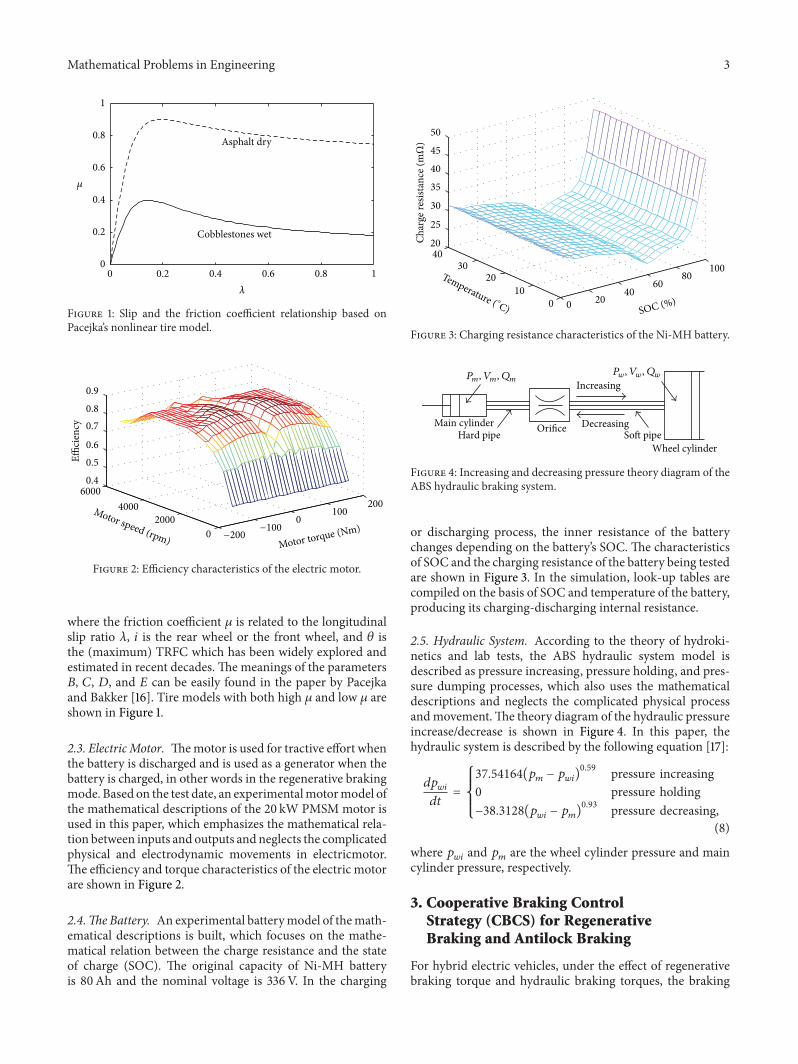
2.3. ElectricMotor. Themotor is used for tractive effort whenthe battery is discharged and is used as a generator when thebattery is charged, in other words in the regenerative brakingmode. Based on the test date, an experimentalmotormodel ofthe mathematical descriptions of the 20 kW PMSM motor isused in this paper, which emphasizes the mathematical rela-tion between inputs and outputs and neglects the complicatedphysical and electrodynamic movements in electricmotor.The efficiency and torque characteristics of the electric motorare shown in Figure 2.
2.4.The Battery. An experimental batterymodel of themath-ematical descriptions is built, which focuses on the mathe-matical relation between the charge resistance and the stateof charge (SOC). The original capacity of Ni-MH batteryis 80Ah and the nominal voltage is 336V. In the charging
0 2040
6080
100
010
2030
4020
25
30
35
40
45
50
SOC (%)
Char
ge re
sista
nce (
mΩ
)
Temperature ( ∘C)
Figure 3: Charging resistance characteristics of the Ni-MH battery.
Main cylinderHard pipe
Pm , Vm , Qm
Orifice
Pw , Vw , Qw
Increasing
DecreasingSoft pipe
Wheel cylinder
Figure 4: Increasing and decreasing pressure theory diagram of theABS hydraulic braking system.
or discharging process, the inner resistance of the batterychanges depending on the battery’s SOC. The characteristicsof SOC and the charging resistance of the battery being testedare shown in Figure 3. In the simulation, look-up tables arecompiled on the basis of SOC and temperature of the battery,producing its charging-discharging internal resistance.
2.5. Hydraulic System. According to the theory of hydroki-netics and lab tests, the ABS hydraulic system model isdescribed as pressure increasing, pressure holding, and pres-sure dumping processes, which also uses the mathematicaldescriptions and neglects the complicated physical processandmovement.The theory diagram of the hydraulic pressureincrease/decrease is shown in Figure 4. In this paper, thehydraulic system is described by the following equation [17]:
𝑑𝑝𝑤𝑖
𝑑𝑡
=
{{
{{
{
37.54164(𝑝𝑚− 𝑝𝑤𝑖)0.59 pressure increasing
0 pressure holding−38.3128(𝑝
𝑤𝑖− 𝑝𝑚)0.93 pressure decreasing,
(8)
where 𝑝𝑤𝑖
and 𝑝𝑚are the wheel cylinder pressure and main
cylinder pressure, respectively.
3. Cooperative Braking ControlStrategy (CBCS) for RegenerativeBraking and Antilock Braking
For hybrid electric vehicles, under the effect of regenerativebraking torque and hydraulic braking torques, the braking
4 Mathematical Problems in Engineering
control system must make the two braking torques worktogether harmoniously to assure the braking safety of vehicleand maintain comfortable sense for driver. In this paper,the cooperative braking control strategy is divided into twoparts: the first part is used to adjust the antilock brakingtorque in the conventional hydraulic braking system usinga sliding mode controller that is based on the target slipratio to control the braking pressure increase, holding, anddecrease; the second part is used to adjust the regenerativebraking torque from the electric motor using a fuzzy logiccontrol strategy that is based on the target slip ratio, batterystate of charge (SOC), and the motor speed to adjust theregenerative braking torque dynamically. In the cooperativebraking control strategy, the wheel slip ratio is the controlcommon variable; the regenerative braking torque and thehydraulic braking toque should be adjusted (increased ordecreased) harmoniously based on the changes of slip ratioto assure the braking stability of vehicle.
In the control strategy, the required braking torque ofdriver 𝑇
𝑟can be expressed as
𝑇𝑟= 𝑇ℎ+ 𝛽 ⋅ 𝑇
𝑚𝑚, (9)
where 𝑇ℎ, 𝛽, and 𝑇
𝑚𝑚are the hydraulic braking torque, the
maximum regenerative braking torque which can be addedby electric motor at that moment (due to the motor speed),and the load signal of motor, respectively.
3.1. Sliding Mode Controller (SMC). The design procedureof sliding mode control methodology consists of two mainsteps: first, a sliding surface that models the desired closed-loop performance is chosen, and then, the control law, suchthat the system state trajectories are forced toward the slidingsurface, is derived [18]. Once the sliding surface is reached,the system state trajectories should stay on it. In this paper,SMC is used to track the target slip ratio. Hence, the switchingfunction 𝑠 is defined as
𝑠 = 𝜆 − 𝜆𝑟, (10)
where 𝜆𝑟is the target wheel slip. The sliding motion occurs
when the state (𝜆𝑟,𝜆𝑟) reaches the switching subspace (a
point in this case) defined by 𝑠 = 0. The control that keepsthe state on the switching subspace is called the equivalentcontrol. In this paper, it is called equivalent control hydraulicbraking torque 𝑇
ℎ−eq. The dynamics in sliding mode can bewritten as
𝑠 = 0, 𝑠 = 0. (11)
If it is assumed that the 𝜆𝑟(the target wheel slip) is constant,
substituting (10) into (11) gives
𝑠 =𝜆 = 0. (12)
Differentiation of (7) with respect to time and the use of (1)–(3) gives
𝜆 =
1
V[−
𝑅
𝐼
(𝐹𝑥𝑅 − 𝑇ℎ− 𝑇𝑓− 𝑇𝑚) + (1 − 𝜆) V]
= −
𝑅
𝐼V[(𝐹𝑥𝑅 − 𝑇𝑓− 𝑇𝑚) −
𝐼
𝑅
(1 − 𝜆) V] +𝑅
𝐼V𝑇ℎ
= 𝐹𝑝(𝜆, 𝑡) + 𝐺
𝑝(𝑡) 𝑢 (𝑡) ,
(13)
where 𝐹𝑝(𝜆, 𝑡) = −(𝑅/𝐼V)[(𝐹
𝑥𝑅 − 𝑇
𝑓− 𝑇𝑚) − (𝐼/𝑅)(1 − 𝜆)V],
𝐺𝑝(𝑡) = (𝑅/𝐼V), and 𝑢(𝑡) = 𝑇
ℎis the control law, assume that
the parameters of the system are well known, and rewriting(13), it can represent the nominal model as
𝜆 = 𝐹0(𝜆, 𝑡) + 𝐺
0(𝑡) 𝑢 (𝑡) , (14)
where 𝐹0(𝜆, 𝑡) and 𝐺
0(𝑡) are the nominal values of 𝐹
𝑝(𝜆, 𝑡)
and 𝐺𝑝(𝑡), respectively. If the uncertainties occur, then the
controlled system can be modified as
𝜆 = [𝐹
0(𝜆, 𝑡) + Δ𝐹 (𝜆, 𝑡)] + [𝐺
0(𝑡) + Δ𝐺 (𝑡)] 𝑢 (𝑡)
= 𝐹0(𝜆, 𝑡) + 𝐺
0(𝑡) 𝑢 (𝑡) + 𝑊,
(15)
where Δ𝐹(𝜆, 𝑡) and Δ𝐺(𝑡) denote the system uncertaintiesand 𝑊 is referred to as the lump uncertainty and is definedas𝑊 = Δ𝐹(𝜆, 𝑡) +Δ𝐺(𝑡)𝑢(𝑡) with the assumption |𝑊| ≤ 𝑘, inwhich 𝑘 is a positive constant of the uncertainty bound andwill be chosen and described later in (20) and (21).
Substituting (13) into (12) gives
𝑇ℎ−eq = 𝐹
𝑥𝑅 − 𝑇𝑓− 𝑇𝑚+ (1 − 𝜆)
𝐼
𝑅
V. (16)
If the system state (𝜆𝑟,𝜆𝑟) is not on the switching subspace,
an additional control term called hitting control brake torqueshould be added to the overall brake torque control signals.When the system state is on the switching subspace, thehitting control is zero. The hitting control is assumed to havethe form
𝑇ℎ−ℎ
= 𝑘 ⋅ sgn (𝑠) . (17)
The hitting control brake torque is determined by the follow-ing reaching condition, where 𝜂 is a strictly positive designparameter:
𝑠 𝑠 ≤ −𝜂 |𝑠| . (18)
Using (10) and (13), (18) can be rewritten as
𝑠𝜆 ≤ −𝜂 |𝑠| . (19)
Substitution of (13) into (19) results in
−
𝑠𝑅
V𝐼[𝐹𝑥𝑅 − 𝑇𝑓− 𝑇𝑚− (𝑇ℎ−eq − 𝑘 ⋅ sgn (𝑠))]
+
𝑠 (1 − 𝜆) V
V≤ −𝜂 |𝑠| .
(20)
Mathematical Problems in Engineering 5
Target slipratio
Real slipratio
+
−
SOCΔ𝜆
n
Fuzzyprocess
FSOCFuzzy
controlrules
Defuzzyprocess
𝛽
Mathematics algorithmof braking system
Regenerativetorque adjustment
FΔ𝜆
Fn
Figure 5: Block diagram of the fuzzy logic controller for the regenerative braking system.
0 1
0
0.2
0.4
0.6
0.8
1NB ZO PMNM NS PS PB
−1
Δ𝜆
(a)
0 0.5 1
0
0.2
0.4
0.6
0.8
1 THTL L HM
SOC, n, 𝛽
(b)
Figure 6: Membership functions for the inputs and outputs of the fuzzy logic controller.
Solving for the switching control gain, the following inequal-ity is obtained:
𝑘 ≥
V𝐼
𝑅
𝜂. (21)
The equation can guarantee that the system is asymptoticallystabilized via the switching surface and compensate uncer-tainties in the simulation model. Chattering phenomenonis an undesirable effect of discontinuous control commandduring sliding mode control. To reduce the chattering phe-nomena, a boundary-layer method with moderate tuning ofa saturation function is used.The sign function is replaced bysaturation function, and the overall hydraulic braking torquecontrol can be rewritten as
𝑇ℎ= 𝑇ℎ−eq + 𝑇ℎ−ℎ = 𝐹
𝑥𝑅 − 𝑇𝑓− 𝑇𝑚
+ (1 − 𝜆)
𝐼
𝑅
V + 𝑘 ⋅ sgn( 𝑠
𝜑
) ,
(22)
where 𝜑 is the boundary layer.
3.2. Fuzzy Logic Control Strategy (FLC). A fuzzy logic controlstrategy is used to adjust the regenerative braking torque
dynamically. There are three inputs in the fuzzy logic con-troller and the three inputs are the difference (Δ𝜆) betweenthe real slip ratio and the target slip ratio, the state ofcharge (SOC) of the battery, and the motor rotation speed 𝑛,respectively. The output is the load signal of electric motor 𝛽.The fuzzy logic controller of the regenerative braking systemis shown in Figure 5.
Based on the simulation analysis, the Δ𝜆 is dividedinto six fuzzy subsets: [NB, NM, NS, ZO, PS, PM, PB],where NB, NM, NS, ZO, PS, PM, and PB are negativebig, negative medium, negative small, zero, positive small,positive medium, and positive big, respectively. Similarly, theSOC, 𝑛, and 𝛽 are divided into five fuzzy subsets: [TL, L, M,H, TH], where TL, L,M,H, and TH are too low, low,medium,high, and too high, respectively. Gaussian and triangularshapes (as shown in Figure 6) are selected for themembershipfunctions of the inputs and outputs.
Assuming that there are 𝑚 rules in a fuzzy rule base andeach of them has the following form:
Rule 𝑖: If Δ𝜆 is 𝑆𝑖and 𝑆𝑂𝐶 is 𝑃
𝑖and 𝑛 is 𝑄
𝑖,
then 𝛽 is 𝛼𝑖,
(23)
6 Mathematical Problems in Engineering
Table 1: Vehicle parameters.
PMSM Power M/G 20/13 KW
Battery Capacity 80AhNominal voltage 336V
Vehicle
Vehicle mass𝑚 1320 kgTire radius 𝑅 0.272m
𝐼𝜔
1.1 kg⋅m2
𝑓 0.015𝐵, 𝐶,𝐷, 𝐸 of tire 8.9, 1.6, 1, 0.5
𝐿, ℎ𝑔, 𝑙𝐹, 𝑙𝑅
2.4, 0.5, 0.9, 1.4 (m)CVT gear ratio 0.451∼2.462
where 𝑆𝑖, 𝑃𝑖, and 𝑄
𝑖are fuzzy subsets and 𝛼
𝑖are the singleton
control actions for 𝑖 = 1, 2, 3, . . . , 𝑚, the defuzzification of thefuzzy logic controller output is accomplished by the methodof center-of-gravity:
𝛽 =
𝑚
∑
𝑖=1
𝜔𝑖× 𝛼𝑖
𝑚
∑
𝑖=1
𝜔𝑖, (24)
where 𝜔𝑖is the firing weight of the 𝑖th rule. Equation (24) can
be rewritten as
𝛽 = 𝛼𝑇
𝜉, (25)
where 𝛼 = [𝛼1, 𝛼2, . . . , 𝛼
𝑚]𝑇 is a parameter vector and 𝜉 =
[𝜉1, 𝜉2, . . . , 𝜉
𝑚]𝑇 is a regressive vector with 𝜉
𝑖defined as
𝜉𝑖=
𝜔𝑖
∑𝑚
𝑖=1𝜔𝑖
. (26)
Figure 7 presents the output surface of the fuzzy inferenceregenerative braking system.TheMamdanimethod is used toperform the fuzzy logic calculation in this paper.
4. Simulation and Analysis
In order to evaluate the performance of the cooperativebraking control strategy, the simulation is implemented inMATLAB/SIMULINK. The simulation parameters of maincomponents of the vehicle are listed in Table 1. In Table 1,these values of 𝑓, 𝐵, 𝐶,𝐷, and 𝐸 are selected from engineers’experiences and tests; values of the other parameters basedon a typical car of our laboratory are selected.The simulationincludes two parts: one part checks the brake stability duringemergency braking, and the other part checks the regen-erative efficiency under the New European Driving Cycle(NEDC).
4.1. Simulation for Emergency Braking. First, the vehicle wasbrought to a steady longitudinal velocity of 30m/s along astraight path. Then, the ABS and the regenerative brakingwere applied on the front wheels simultaneously. To increasestability and manoeuvrability of the vehicle and to decreasethe stopping distance during emergency braking, the CBCSis implemented to maintain the target slip ratio value of 0.2.The simulation results are shown in Figures 8 and 9.
The wheel speed and slip ratio with conventional controland SMC control are compared in Figures 8(a) and 8(b),respectively. As can be seen in Figures 8(a) and 8(b), theconventional controller and SMC try to stop the car quicklyand keep the slip ratio at the optimal value of 0.2; the initialaction of the SMC ABS is similar to conventional brakinguntil the sliding surface is reached, and then there is a sharpfall in the wheel speed for SMC, which is due to the hittingcontrol; large oscillations can be observed in the conventionalcontroller; it may be significantly affected by changes in theparameters. The oscillation when using the SMC is muchsmaller than that when using the conventional controller;perhaps the SMC has more robustness against parametervariation. The sliding mode ABS control produces smoothervariations in wheel speed and the slip ratio as comparedto the conventional ABS system, thereby improving brakingstability and passenger comfort. It can be seen that thewheels are never locked during the whole braking processand the time taken for stopping the car is less than 0.2 swhen emergency braking with SMCABS is used as comparedto emergency braking with conventional ABS. Hence, thecontrol performance of the proposed SMC is far better thanthat of the conventional controller.
Figures 9(a) and 9(b) show the variations in the brakingtorque and battery SOC in an emergency braking condition.The variations of the hydraulic braking torque and regen-erative braking torque are shown in Figure 9(a). Initially,to increase braking stability and manoeuvrability of thevehicle, the hydraulic braking torque is much larger thanthe regenerative braking torque, and then in order to getmore regenerative energy, the cooperative control strategydepresses the hydraulic braking torque of the front axle andincreases the regenerative braking toque at the same time.Thehydraulic braking torque and regenerative braking torquecan cooperate well under the braking control strategy. InFigure 9(b), the battery SOC shows an increased value ofabout 1.6 percent during emergency braking. Note that if theoriginal battery SOC is small, then braking from the sameinitial speed to complete rest produces more change in thebattery SOC as compared to the case when the battery isinitially at a higher SOC. For very large battery SOC, nofurther charging may be possible and regenerative brakingfails.
4.2. Simulation for the NEDC. Simulation results are shownin Figure 10. Figure 10(a) shows the vehicle speed of the NewEuropean Driving Cycle (NEDC). Figure 10(b) shows thevariations of the hydraulic braking torque and regenerativebraking torque. As shown in Figure 10(b), in normal brakingprocess, the electric motor acts as the main braking source,and the hydraulic braking system works only to ensure theparking; in an emergency braking condition, to increasebraking stability, the hydraulic braking system acts as themain braking source. The battery current (Figure 10(c))shows a positive value when the battery is charged and showsa negative value when the battery is discharged. The batterySOC (Figure 10(d)) decreases when the motor is used topropel the vehicle and increases when the motor is used asa generator. The final battery SOC by the FLC control is
Mathematical Problems in Engineering 7
0
0.5
1
0
1
0.2
0.4
0.6
0.8
SOC Δ𝜆
𝛽
−1
(a)
00.5
1
0
0.5
1
0.2
0.4
0.6
0.8
SOCn
𝛽
(b)
Figure 7: Output surface of the fuzzy inference regenerative braking system.
0 1 2 3 40
5
10
15
20
25
30
35
Time (s)
Spee
d (m
/s)
Vehicle speedWheel speed
SMC control
Conventional control
(a)
0 0.2 0.4 0.6 0.80
0.05
0.1
0.15
0.2
0.25
Time (s)
Slip
ratio
Conventional controlSMC control
(b)
Figure 8: Comparison of (a) vehicle speed and wheel speed and (b) slip ratio for conventional control and SMC control.
0 1 2 3 4
0
Time (s)
Brak
ing
torq
ue (N
m)
Regenerative braking torque
Hydraulic braking torque−50
−100
−150
−200
−250
−300
(a)
0 1 2 3 461.5
62
62.5
63
63.5
Time (s)
Batte
ry S
OC
(b)
Figure 9: (a) Regenerative braking torque and hydraulic braking torque and (b) battery SOC for CBCS during emergency braking by ABSand regenerative braking.
higher than that by the conventional control, which impliesthat more electric energy is stored by the FCS control. InFigure 10(e), the regenerated energy stored in battery iscompared. As shown in Figure 10(e), the stored energy by
the FCS control shows a higher value than that by theconventional control. Since the stored energy can be reused topropel the vehicle, the vehicle fuel economy can be improvedby the amount of increased stored energy.
Mathematical Problems in Engineering 9
5. Conclusion
A new cooperative braking control strategy (CBCS) for aparallel hybrid electric vehicle is proposed in this paper. TheCBCS combines a sliding mode controller and a fuzzy logiccontrol strategy to ensure the vehicle’s longitudinal brakingperformance, which keeps the wheels from being lockedand regenerates more energy effectively. The simulationshows that the model of the HEV’s braking system andthe cooperative braking control strategy developed in thispaper are right. It is also found from the simulation thatthe cooperative braking control strategy suggested in thispaper provides satisfactory braking performance, passengercomfort, and high regenerative efficiency. Although thesimulation results have a certain guiding significance for realapplications, the deviation between the simulationmodel andthe braking system of actual vehicle is inevitable. Hence, thereal vehicle test and a hardware-in-the-loop simulation withcosimulations between MATLAB/SIMULINK and dSPACEwill be researched to validate the effectiveness of the proposedcooperative braking control strategy in the future.
Acknowledgments
The paper is supported by NSFC (no. 51105074) and Foun-dation of State Key Laboratory of Mechanical Transmission(SKLMT-KFKT-201206).
References
[1] C. Park, K. Kook, K. Oh, D. Kim, and H. Kim, “Operationalgorithms for a fuel cell hybrid electric vehicle,” InternationalJournal of Automotive Technology, vol. 6, no. 4, pp. 429–436,2005.
[2] H. Yeo and H. Kim, “Hardware-in-the-loop simulation ofregenerative braking for a hybrid electric vehicle,” Journal ofAutomobile Engineering, vol. 216, no. 11, pp. 855–864, 2002.
[3] G. Sovran and D. Blaser, “Quantifying the potential impacts ofregenerative braking on a vehicle’s tractive fuel consumption forthe U.S., European, and Japanese driving schedules,” SAE Paper2006-01-0664, 2006.
[4] Y. Gao, “Electronic braking system of EV and HEV integrationof regenerative braking, automatic braking force control andABS,” SAE Paper 2001-01-2478, 2001.
[5] K. Muta, M. Yamazaki, and J. Tokieda, “Develop-ment of new-generation hybrid system THS II—drastic improvement ofpower performance and fuel economy,” SAE Paper 2004-01-0064, 2004.
[6] F. Wyczalk, “Regenerative braking concepts for electric vehicle-a primer,” SAE Paper 920648, 1992.
[7] H. Yeo, C. Song, C. Kim, and H. Kim, “Hardware in theloop simulation of hybrid vehicle for optimal engine operationby CVT ratio control,” International Journal of AutomotiveTechnology, vol. 5, no. 3, pp. 201–208, 2004.
[8] Y. Luo, P. Li, D. Jin, and K. Li, “A study on regenerativebraking strategy based on optimal control theory,” AutomotiveEngineering, vol. 28, no. 4, pp. 356–360, 2006.
[9] G. Yin, N. Chen, and P. Li, “Improving handling stabilityperformance of four-wheel steering vehicle via 𝜇-synthesis
robust control,” IEEE Transactions on Vehicular Technology, vol.56, no. 5, pp. 2432–2439, 2007.
[10] O. Tur, O.Ustun, andR.N. Tuncay, “An introduction to regener-ative braking of electric vehicles as anti-lock braking system,” inProceedings of the IEEE Intelligent Vehicles Symposium (IV ’07),pp. 944–948, Istanbul, Turkey, June 2007.
[11] T. Okano, S. Sakai, T. Uchida, and Y. Hori, “Braking per-formance improvement for hybrid electric vehicle based onelectric motor’s quick torque response,” in Proceedings of the19th International Battery Hybrid and Fuel Cell Electric VehicleSymposium, pp. 1285–1296, Busan, Republic of Korea, October2002.
[12] J.-H. Pu, C.-L. Yin, and J.-W. Zhang, “Fuzzy torque controlstrategy for parallel hybrid electric vehicles,” InternationalJournal of Automotive Technology, vol. 6, no. 5, pp. 529–536,2005.
[13] D. Peng, Y. Zhang, C.-L. Yin, and J.-W. Zhang, “Combinedcontrol of a regenerative braking and antilock braking systemfor hybrid electric vehicles,” International Journal of AutomotiveTechnology, vol. 9, no. 6, pp. 749–757, 2008.
[14] L. Wu and D. W. C. Ho, “Sliding mode control of singularstochastic hybrid systems,” Automatica, vol. 46, no. 4, pp. 779–783, 2010.
[15] R. Yang, H. Gao, and P. Shi, “Delay-dependent robust𝐻∞con-
trol for uncertain stochastic time-delay systems,” InternationalJournal of Robust and Nonlinear Control, vol. 20, no. 16, pp.1852–1865, 2010.
[16] H. B. Pacejka andE. Bakker, “Magic formula tyremodel,”VehicleSystem Dynamics, vol. 21, no. 1, pp. 1–18, 1992.
[17] J. Li, J. W. Zhang, and F. Yu, “An investigation into fuzzy con-troller for anti-lock braking system based on road autonomousidentification,” SAE Paper 2001-01-0599, 2001.
[18] L. Wu and W. X. Zheng, “Passivity-based sliding mode controlof uncertain singular time-delay systems,” Automatica, vol. 45,no. 9, pp. 2120–2127, 2009.