The Finite ElementMethod is a well-known technique, being extensively applied in different areas. Studies using the Finite ElementMethod (FEM) are targeted to improve cardiac ablation procedures. For such simulations, the finite elementmeshes should considerthe size and histological features of the target structures. However, it is possible to verify that somemethods or tools used to generatemeshes of human body structures are still limited, due to nondetailed models, nontrivial preprocessing, or mainly limitation in theuse condition. In this paper, alternatives are demonstrated to solid modeling and automatic generation of highly refined tetrahedralmeshes, with quality compatible with other studies focused on mesh generation. The innovations presented here are strategies tointegrate Open Source Software (OSS). The chosen techniques and strategies are presented and discussed, considering cardiacstructures as a first application context.
1. Introduction
The increased use of minimally invasive surgical proceduresin medicine is a reality, with applications in different special-ties. The small incisions ensure the patient smaller exposureto infections, as well as a quicker recovery. The radiofre-quency cardiac ablation is a good example of it, being exten-sively used for over 10 years in the treatment of tachycardia,atrial fibrillation, and atrial flutter [1–4]. This technique isnot free from complications, although it has advanced inthe last decade. The esophageal injury is a common damage,characterized by the union of tissues from the left atriumand esophagus, through necrosis [1, 4]. The consequence forthe patient is death caused by internal bleeding, as blood isdiverted directly to the stomach, when it is not noticed by thephysician.
In the literature, studies using the Finite ElementMethod(FEM) are targeted to improve cardiac ablation procedureand reduce possible complications, such as esophageal injury.
It is possible to highlight that the nucleus of the problemis monitoring the temperatures in the tissues involved moreaccurately. This approach is not simple, and the computa-tional simulation using FEM has contributed significantly tothe improvement of this technique [5–12]. For such simula-tions, the finite element meshes should consider the size andhistological features of the target structures. Furthermore,the quality of the meshes is another fundamental propertyto properly simulate the desired phenomena. The techniqueswhich are able to generate meshes with such characteristicsare preferred, and when they are generated with open sourcecodes, they make easier tests with no user restrictions.These properties can guarantee more accurate and clinicallyrelevant simulations.
In this context, it is possible to verify that some methodsor tools used to generate meshes of human body structuresare still limited by providing or using nondetailed models[5–8, 10, 13–15], by the need of nontrivial preprocessing,which is a primary step applied to define, extract, or change
2 International Journal of Biomedical Imaging
the anatomical features (boundary domain) required bymeshing generation step [7, 11, 15–18] or due to limitationsof the user condition [5, 6, 8, 12, 13, 18, 19]. One of thereasons for this finding is the necessary commitment to rep-resent the complicated geometries of the involved domains,which requires sophisticated resources being sometimesunder development in specific tools for geometric model-ing and mesh discretization [20, 21]. A typical integratedsoftware tool to construct three-dimensional domains andfinite element meshes may have a development time cycle ofmore than 10 years [22, 23] and frequently with exceptionsto allow linking with other mesh generators. An alternative isintegratingOpen Source Software packages dedicated to solidmodeling with automatic generation of tetrahedral meshes,which are available in the literature. This strategy bringsobvious advantages in the context of FEM simulations.
With these findings, the present paper demonstrates alter-natives to solid modeling and automatic generation of highlyrefined tetrahedral meshes and with quality compatible withother studies focused on mesh generation. The innovationspresented here are strategies to integrate Open Source Soft-ware (OSS). The chosen tools were the Blender software [24]as solidmodeler and the TetGen as automaticmesh generator[25], which uses the Delaunay tetrahedralization [25, 26].Furthermore, in this study we demonstrate cardiac structuresas a first application context, motivated by the importancethat the meshes of these structures represent for studies ofcardiac ablation. In the next sections a discussion concerningour strategy for software integration and performance tests inrealistic application domain are presented.
2. Material and Methods
The proposed methodology for solid modeling and auto-matic generation of tetrahedral meshes was organized inSection 2.1, with details about the defined anatomical prop-erties for the application context; Section 2.2, with defini-tions of the used packages and corresponding justifications;Section 2.3, with details about the recommendations to dis-cretize domains; and Section 2.4, with specifications from theintegration process of the models built on the solid modelerto the algorithm used in the automatic mesh generator. Theproposal will be described in detail in the next subsections.
2.1. Application: Features of Cardiac Structures. Thechoices ofcardiac structures were motivated by the complicated geo-metric domain and by the clinical relevance that thesestructures represent for the investigation of esophageal injury.Therefore, the model defined in our study was composedof cardiac regions consisting of two main parts: the rightportion (venous) and the left portion (arterial). Each por-tion has an atrium, a ventricle, and valves: bicuspid, andtricuspid, pulmonary or aortic valve. The trunks of aorta andpulmonary artery were represented from their connectionswith the atriums to the beginning of their ramifications.The dimensions of these structures are presented in Table 1
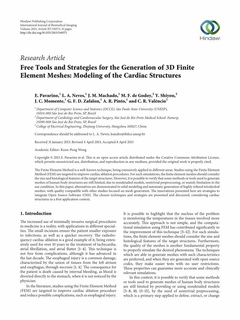
Table 1: Values used to define the heart model. Considering thediastolic dimensions of an adult heart [27–29].
Figure 1: Example of echocardiography used in the modelingprocess. The aortic valve and the pulmonary valve do not appear inthis figure.
[27–29], defined in cardiac diastole (period of heart musclerelaxation) and values present in major axes. The presence ofsome structures is visualized on an echocardiographic image(Figure 1), which was used as another reference during themodeling process.
2.2. Free and Open Source Packages. Creating complex three-dimensionalmodels is not a trivial task, especiallywithout thesupport of sophisticated modelers and already equipped withresources to integrate it with algorithms responsible for meshgeneration. The Blender package [24] maintained by BlenderFoundation was chosen.This package is an integrated systemof tools, a multiplatform and contains resources to exportand import objects in different formats, through scripts.Scripts are useful for automating methods, navigating andmanipulating the discretized geometric domain. Moreover,Blender is available under a dual license, Blender License (BL)and GNU General Public License. With all these resources,it becomes possible to represent the domain of interest anduse scripts, written in Python language, to export featuresrequired by the automatic mesh generator.
International Journal of Biomedical Imaging 3
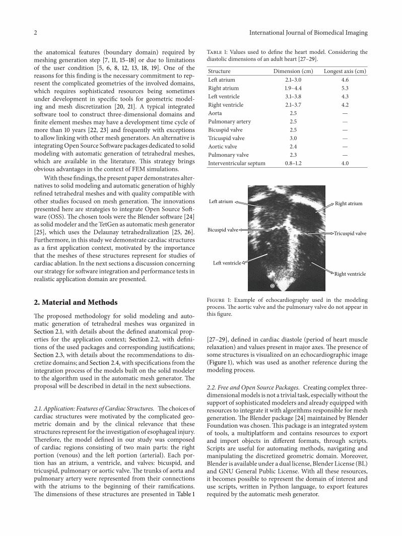
Figure 2: Chosen regions for quadrilateral or rectangular faces(blue), triangular faces (red), and with increased density of vertices(yellow).
The stage for automatic generation of tetrahedral meshesis not a trivial task, a fact that limits the use of a singlealgorithm to discretize the most different contexts. The algo-rithms commonly applied to generate tetrahedral mesheshave good and bad points [26, 30–32], some of which requiremanual interference in the domain to obtain the desireddiscretization. Although there are different methods forgenerating three-dimensionalmeshes, we chose theDelaunayalgorithm [25, 31] for being one of the most popular and oneof the most efficient algorithms [30], available in the TetGenpackage [26]. Just as Blender, TetGen is an Open Source Soft-ware (OSS) and is available under MIT License.This packageis maintained by the research group called Numerical Math-ematics and Scientific Computing, Weierstrass Institute forApplied Analysis and Stochastics (WIAS), Berlin, Germany.
The selected packages for the models construction andautomatic generation of meshes were explored in a computerwith a 2.40GHz quad core processor and 16GB of RAMmemory. The operating system used uses 64-bit architecture,running Blender in version 2.49b and TetGenmesh generatorin version 1.4.
2.3. Definition of Strategies for Solid Construction. The rep-resentation of solids in the Blender package must respecttwo strategies to ensure the integration with the automaticmesh generator. The strategies or recommendations are (1)definitions of faces and (2) density control of vertices,whereas the application of eachmust consider the complexityof the specific region.
The strategy definitions of faces consist of choosing themost appropriate types of faces to discretize a solid. Regularor noncomplex regions of the specific domain must be dis-cretized with quadrilateral or rectangular faces. A quadrilat-eral or rectangular face can be modified to fill regions with
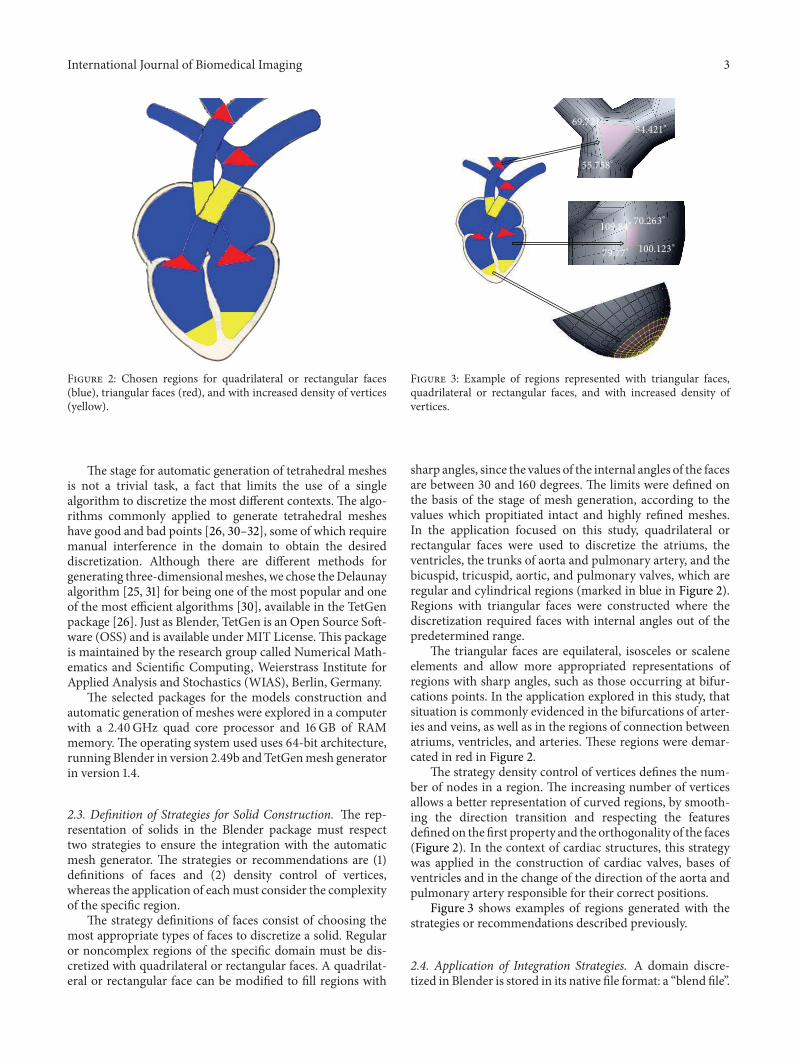
69.721∘54.421∘
55.758∘
109.84∘70.263∘
100.123∘79.77∘
Figure 3: Example of regions represented with triangular faces,quadrilateral or rectangular faces, and with increased density ofvertices.
sharp angles, since the values of the internal angles of the facesare between 30 and 160 degrees. The limits were defined onthe basis of the stage of mesh generation, according to thevalues which propitiated intact and highly refined meshes.In the application focused on this study, quadrilateral orrectangular faces were used to discretize the atriums, theventricles, the trunks of aorta and pulmonary artery, and thebicuspid, tricuspid, aortic, and pulmonary valves, which areregular and cylindrical regions (marked in blue in Figure 2).Regions with triangular faces were constructed where thediscretization required faces with internal angles out of thepredetermined range.
The triangular faces are equilateral, isosceles or scaleneelements and allow more appropriated representations ofregions with sharp angles, such as those occurring at bifur-cations points. In the application explored in this study, thatsituation is commonly evidenced in the bifurcations of arter-ies and veins, as well as in the regions of connection betweenatriums, ventricles, and arteries. These regions were demar-cated in red in Figure 2.
The strategy density control of vertices defines the num-ber of nodes in a region. The increasing number of verticesallows a better representation of curved regions, by smooth-ing the direction transition and respecting the featuresdefined on the first property and the orthogonality of the faces(Figure 2). In the context of cardiac structures, this strategywas applied in the construction of cardiac valves, bases ofventricles and in the change of the direction of the aorta andpulmonary artery responsible for their correct positions.
Figure 3 shows examples of regions generated with thestrategies or recommendations described previously.
2.4. Application of Integration Strategies. A domain discre-tized in Blender is stored in its native file format: a “blend file”.
4 International Journal of Biomedical Imaging
Pointer Pointer Pointer
Object
Mesh size, localization,and rotation
Mesh Material
Lists of vertices, faces,and edges
Colors and textures ofmeshes
Id Id Id
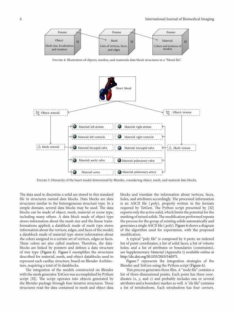
Figure 4: Illustration of objects, meshes, and materials data block structures in a “blend file”.
Heart .blend
Object: venous
Mesh: venous
Material: left atrium
Material: left ventricle
Material: bicuspid valve
Material: aortic valve
Material: aorta
Material: right atrium
Material: right ventricle
Material: tricuspid valve
Material: pulmonary valve
Material: pulmonary artery
Object: arterial
Mesh: arterial
Figure 5: Hierarchy of the heart model determined by Blender, considering object, mesh, and material data blocks.
The data used to discretize a solid are stored in this standardfile in structures named data blocks. Data blocks are datastructures similar to the heterogeneous structure type. In asimple domain, several data blocks may be used. The datablocks can be made of object, mesh, material or scene type,including many others. A data block made of object typestores information about the mesh size and the linear trans-formations applied; a datablock made of mesh type storesinformation about the vertices, edges, and faces of the model;a datablock made of material type stores information aboutthe colors assigned to a certain set of vertices, edges or faces.These colors are also called markers. Therefore, the data-blocks are linked by pointers and defines a data structureof tree type (Figure 4). Figure 5 exemplifies the structuresdescribed for material, mesh, and object datablocks used torepresent each cardiac structure, based on Blender Architec-ture, requiring a total of 14 datablocks.
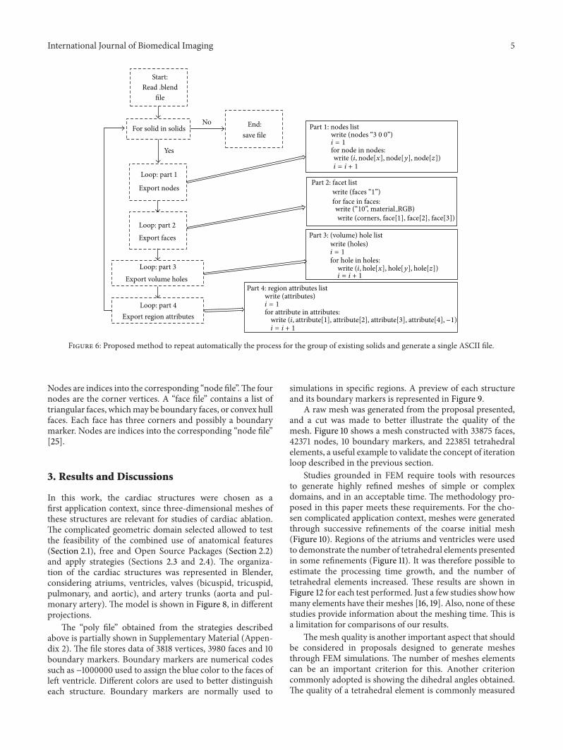
The integration of the models constructed on Blenderwith themesh generator TetGenwas accomplished by Pythonscript [32]. The script operates into objects generated bythe Blender package through four iterative structures. Thesestructures read the data contained in mesh and object data
blocks and translate the information about vertices, faces,holes, and attributes accordingly. The processed informationis an ASCII file (.poly), properly written in the formatsrequired by TetGen. The Python script presented by [32]exports only the active solid, which limits the potential for themeshing ofmixed solids.Themodification performed repeatsthe process for the group of existing solids automatically andgenerates a single ASCII file (.poly). Figure 6 shows a diagramof the algorithm used for exportation, with the proposedmodification.
A typical “poly file” is composed by 4 parts: an indexedlist of point coordinates; a list of solid faces; a list of volumeholes; and a list of attributes or boundaries (constraints),see Supplementary Material (Appendix 1) available online athttp://dx.doi.org/10.1155/2013/540571.
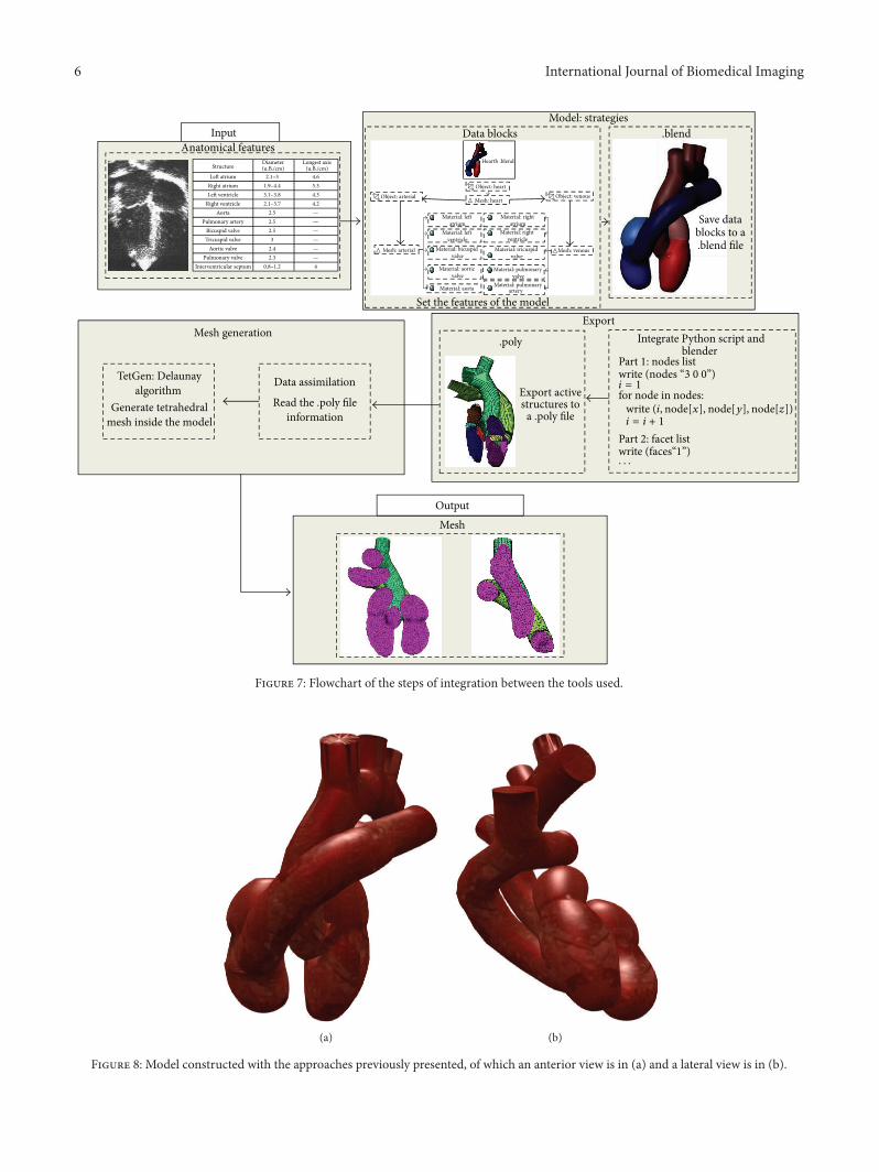
Figure 7 represents the integration strategies of theBlender and TetGen using the Python script (Figure 6).
This process generates three files. A “node file” contains alist of three-dimensional points. Each point has three coor-dinates (x, y, and z) and probably includes one or severalattributes and a boundary marker as well. A “ele file” containsa list of tetrahedrons. Each tetrahedron has four corners.
write (“10”, material RGB)write (corners, face[1], face[2], face[3])
Figure 6: Proposed method to repeat automatically the process for the group of existing solids and generate a single ASCII file.
Nodes are indices into the corresponding “node file”.The fournodes are the corner vertices. A “face file” contains a list oftriangular faces, whichmay be boundary faces, or convex hullfaces. Each face has three corners and possibly a boundarymarker. Nodes are indices into the corresponding “node file”[25].
3. Results and Discussions
In this work, the cardiac structures were chosen as afirst application context, since three-dimensional meshes ofthese structures are relevant for studies of cardiac ablation.The complicated geometric domain selected allowed to testthe feasibility of the combined use of anatomical features(Section 2.1), free and Open Source Packages (Section 2.2)and apply strategies (Sections 2.3 and 2.4). The organiza-tion of the cardiac structures was represented in Blender,considering atriums, ventricles, valves (bicuspid, tricuspid,pulmonary, and aortic), and artery trunks (aorta and pul-monary artery). The model is shown in Figure 8, in differentprojections.
The “poly file” obtained from the strategies describedabove is partially shown in Supplementary Material (Appen-dix 2). The file stores data of 3818 vertices, 3980 faces and 10boundary markers. Boundary markers are numerical codessuch as −1000000 used to assign the blue color to the faces ofleft ventricle. Different colors are used to better distinguisheach structure. Boundary markers are normally used to
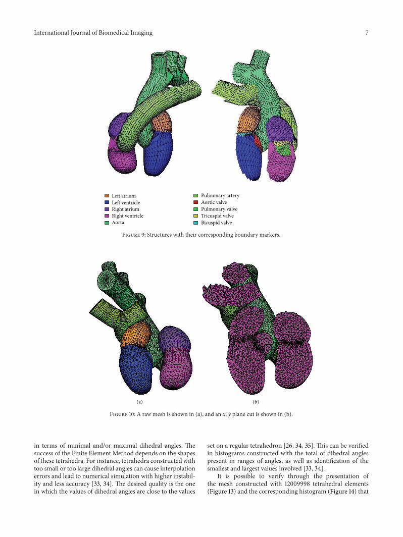
simulations in specific regions. A preview of each structureand its boundary markers is represented in Figure 9.
A raw mesh was generated from the proposal presented,and a cut was made to better illustrate the quality of themesh. Figure 10 shows a mesh constructed with 33875 faces,42371 nodes, 10 boundary markers, and 223851 tetrahedralelements, a useful example to validate the concept of iterationloop described in the previous section.
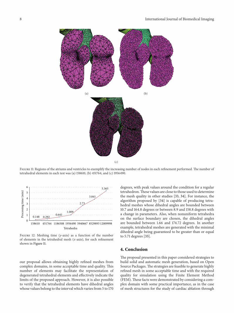
Studies grounded in FEM require tools with resourcesto generate highly refined meshes of simple or complexdomains, and in an acceptable time. The methodology pro-posed in this paper meets these requirements. For the cho-sen complicated application context, meshes were generatedthrough successive refinements of the coarse initial mesh(Figure 10). Regions of the atriums and ventricles were usedto demonstrate the number of tetrahedral elements presentedin some refinements (Figure 11). It was therefore possible toestimate the processing time growth, and the number oftetrahedral elements increased. These results are shown inFigure 12 for each test performed. Just a few studies show howmany elements have their meshes [16, 19]. Also, none of thesestudies provide information about the meshing time. This isa limitation for comparisons of our results.
Themesh quality is another important aspect that shouldbe considered in proposals designed to generate meshesthrough FEM simulations. The number of meshes elementscan be an important criterion for this. Another criterioncommonly adopted is showing the dihedral angles obtained.The quality of a tetrahedral element is commonly measured
Figure 7: Flowchart of the steps of integration between the tools used.
(a) (b)
Figure 8: Model constructed with the approaches previously presented, of which an anterior view is in (a) and a lateral view is in (b).
International Journal of Biomedical Imaging 7
Left atrium
Bicuspid valve
Pulmonary artery
Pulmonary valveAortic valve
Aorta
Left ventricleRight atrium
Tricuspid valveRight ventricle
Figure 9: Structures with their corresponding boundary markers.
(a) (b)
Figure 10: A raw mesh is shown in (a), and an x, y plane cut is shown in (b).
in terms of minimal and/or maximal dihedral angles. Thesuccess of the Finite Element Method depends on the shapesof these tetrahedra. For instance, tetrahedra constructed withtoo small or too large dihedral angles can cause interpolationerrors and lead to numerical simulation with higher instabil-ity and less accuracy [33, 34]. The desired quality is the onein which the values of dihedral angles are close to the values
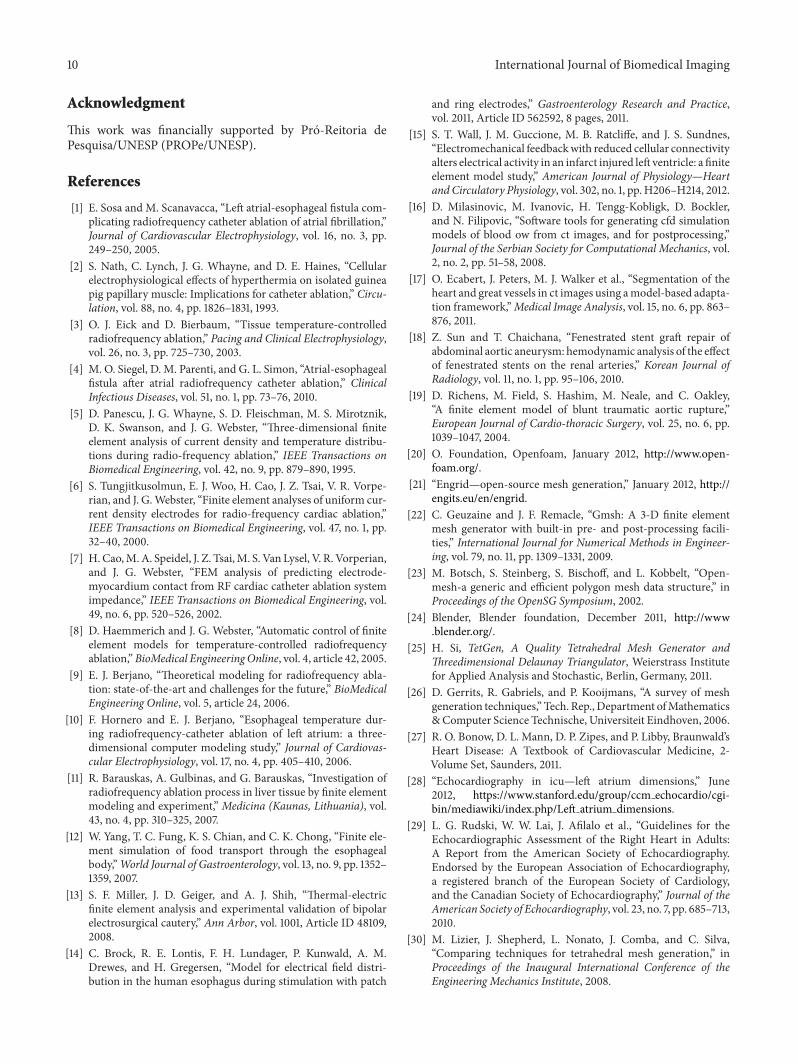
set on a regular tetrahedron [26, 34, 35]. This can be verifiedin histograms constructed with the total of dihedral anglespresent in ranges of angles, as well as identification of thesmallest and largest values involved [33, 34].
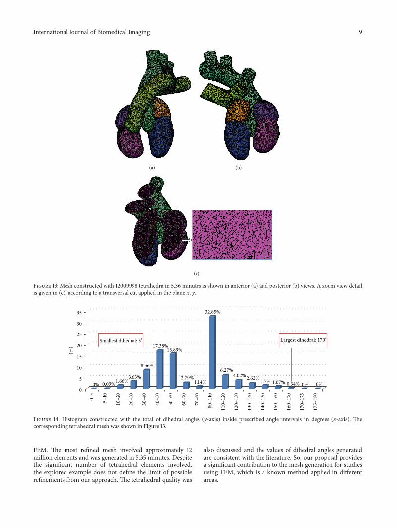
It is possible to verify through the presentation ofthe mesh constructed with 12009998 tetrahedral elements(Figure 13) and the corresponding histogram (Figure 14) that
8 International Journal of Biomedical Imaging
(a) (b)
(c)
Figure 11: Regions of the atriums and ventricles to exemplify the increasing number of nodes in each refinement performed. The number oftetrahedral elements in each test was (a) 158610, (b) 451764, and (c) 1956490.
Figure 12: Meshing time (y-axis) as a function of the numberof elements in the tetrahedral mesh (x-axis), for each refinementshown in Figure 11.
our proposal allows obtaining highly refined meshes fromcomplex domains, in some acceptable time and quality. Thisnumber of elements may facilitate the representation ofdegenerated tetrahedral elements and effectively indicate thelimits of the proposed approach. However, it is also possibleto verify that the tetrahedral elements have dihedral angleswhose values belong to the interval which varies from 5 to 170
degrees, with peak values around the condition for a regulartetrahedron.These values are close to those used to determinethe mesh quality in other studies [33, 34]. For instance, thealgorithm proposed by [34] is capable of producing tetra-hedral meshes whose dihedral angles are bounded between10.7 and 164.8 degrees or between 8.9 and 158.8 degrees witha change in parameters. Also, when nonuniform tetrahedraon the surface boundary are chosen, the dihedral anglesare bounded between 1.66 and 174.72 degrees. In anotherexample, tetrahedral meshes are generated with the minimaldihedral angle being guaranteed to be greater than or equalto 5.71 degrees [33].
4. Conclusion
The proposal presented in this paper considered strategies tobuild solid and automatic mesh generation, based on OpenSource Packages.The strategies are feasible to generate highlyrefined mesh in some acceptable time and with the requiredquality for simulation using the Finite Element Method(FEM).These facts were demonstrated by considering a com-plex domain with some practical importance, as in the caseof mesh structures for the study of cardiac ablation through
International Journal of Biomedical Imaging 9
(a) (b)
(c)
Figure 13: Mesh constructed with 12009998 tetrahedra in 5.36 minutes is shown in anterior (a) and posterior (b) views. A zoom view detailis given in (c), according to a transversal cut applied in the plane x, y.
35
30
25
20
15
10
5
0
(%)
0–5
5–10
10–2
0
20–3
0
30–4
0
40–5
0
50–6
0
60–7
0
70–8
0
80–1
10
110–
120
120–
130
130–
140
140–
150
150–
160
160–
170
170–
175
175–
180
Smallest dihedral: 5∘ Largest dihedral: 170∘
0% 0.09%1.66%3.63%
8.56%
17.38%15.89%
2.79%1.14%
32.85%
6.27%4.02%2.62% 1.7% 0.34% 0% 0%1.07%
Figure 14: Histogram constructed with the total of dihedral angles (y-axis) inside prescribed angle intervals in degrees (x-axis). Thecorresponding tetrahedral mesh was shown in Figure 13.
FEM. The most refined mesh involved approximately 12million elements and was generated in 5.35 minutes. Despitethe significant number of tetrahedral elements involved,the explored example does not define the limit of possiblerefinements from our approach. The tetrahedral quality was
also discussed and the values of dihedral angles generatedare consistent with the literature. So, our proposal providesa significant contribution to the mesh generation for studiesusing FEM, which is a known method applied in differentareas.
10 International Journal of Biomedical Imaging
Acknowledgment
This work was financially supported by Pro-Reitoria dePesquisa/UNESP (PROPe/UNESP).
References
[1] E. Sosa and M. Scanavacca, “Left atrial-esophageal fistula com-plicating radiofrequency catheter ablation of atrial fibrillation,”Journal of Cardiovascular Electrophysiology, vol. 16, no. 3, pp.249–250, 2005.
[2] S. Nath, C. Lynch, J. G. Whayne, and D. E. Haines, “Cellularelectrophysiological effects of hyperthermia on isolated guineapig papillary muscle: Implications for catheter ablation,” Circu-lation, vol. 88, no. 4, pp. 1826–1831, 1993.
[3] O. J. Eick and D. Bierbaum, “Tissue temperature-controlledradiofrequency ablation,” Pacing and Clinical Electrophysiology,vol. 26, no. 3, pp. 725–730, 2003.
[4] M. O. Siegel, D. M. Parenti, and G. L. Simon, “Atrial-esophagealfistula after atrial radiofrequency catheter ablation,” ClinicalInfectious Diseases, vol. 51, no. 1, pp. 73–76, 2010.
[5] D. Panescu, J. G. Whayne, S. D. Fleischman, M. S. Mirotznik,D. K. Swanson, and J. G. Webster, “Three-dimensional finiteelement analysis of current density and temperature distribu-tions during radio-frequency ablation,” IEEE Transactions onBiomedical Engineering, vol. 42, no. 9, pp. 879–890, 1995.
[6] S. Tungjitkusolmun, E. J. Woo, H. Cao, J. Z. Tsai, V. R. Vorpe-rian, and J. G.Webster, “Finite element analyses of uniform cur-rent density electrodes for radio-frequency cardiac ablation,”IEEE Transactions on Biomedical Engineering, vol. 47, no. 1, pp.32–40, 2000.
[7] H. Cao,M.A. Speidel, J. Z. Tsai,M. S. Van Lysel, V. R. Vorperian,and J. G. Webster, “FEM analysis of predicting electrode-myocardium contact from RF cardiac catheter ablation systemimpedance,” IEEE Transactions on Biomedical Engineering, vol.49, no. 6, pp. 520–526, 2002.
[8] D. Haemmerich and J. G. Webster, “Automatic control of finiteelement models for temperature-controlled radiofrequencyablation,”BioMedical Engineering Online, vol. 4, article 42, 2005.
[9] E. J. Berjano, “Theoretical modeling for radiofrequency abla-tion: state-of-the-art and challenges for the future,” BioMedicalEngineering Online, vol. 5, article 24, 2006.
[10] F. Hornero and E. J. Berjano, “Esophageal temperature dur-ing radiofrequency-catheter ablation of left atrium: a three-dimensional computer modeling study,” Journal of Cardiovas-cular Electrophysiology, vol. 17, no. 4, pp. 405–410, 2006.
[11] R. Barauskas, A. Gulbinas, and G. Barauskas, “Investigation ofradiofrequency ablation process in liver tissue by finite elementmodeling and experiment,” Medicina (Kaunas, Lithuania), vol.43, no. 4, pp. 310–325, 2007.
[12] W. Yang, T. C. Fung, K. S. Chian, and C. K. Chong, “Finite ele-ment simulation of food transport through the esophagealbody,”World Journal of Gastroenterology, vol. 13, no. 9, pp. 1352–1359, 2007.
[13] S. F. Miller, J. D. Geiger, and A. J. Shih, “Thermal-electricfinite element analysis and experimental validation of bipolarelectrosurgical cautery,” Ann Arbor, vol. 1001, Article ID 48109,2008.
[14] C. Brock, R. E. Lontis, F. H. Lundager, P. Kunwald, A. M.Drewes, and H. Gregersen, “Model for electrical field distri-bution in the human esophagus during stimulation with patch
and ring electrodes,” Gastroenterology Research and Practice,vol. 2011, Article ID 562592, 8 pages, 2011.
[15] S. T. Wall, J. M. Guccione, M. B. Ratcliffe, and J. S. Sundnes,“Electromechanical feedbackwith reduced cellular connectivityalters electrical activity in an infarct injured left ventricle: a finiteelement model study,” American Journal of Physiology—Heartand Circulatory Physiology, vol. 302, no. 1, pp. H206–H214, 2012.
[16] D. Milasinovic, M. Ivanovic, H. Tengg-Kobligk, D. Bockler,and N. Filipovic, “Software tools for generating cfd simulationmodels of blood ow from ct images, and for postprocessing,”Journal of the Serbian Society for Computational Mechanics, vol.2, no. 2, pp. 51–58, 2008.
[17] O. Ecabert, J. Peters, M. J. Walker et al., “Segmentation of theheart and great vessels in ct images using amodel-based adapta-tion framework,”Medical Image Analysis, vol. 15, no. 6, pp. 863–876, 2011.
[18] Z. Sun and T. Chaichana, “Fenestrated stent graft repair ofabdominal aortic aneurysm: hemodynamic analysis of the effectof fenestrated stents on the renal arteries,” Korean Journal ofRadiology, vol. 11, no. 1, pp. 95–106, 2010.
[19] D. Richens, M. Field, S. Hashim, M. Neale, and C. Oakley,“A finite element model of blunt traumatic aortic rupture,”European Journal of Cardio-thoracic Surgery, vol. 25, no. 6, pp.1039–1047, 2004.
[20] O. Foundation, Openfoam, January 2012, http://www.open-foam.org/.
[21] “Engrid—open-source mesh generation,” January 2012, http://engits.eu/en/engrid.
[22] C. Geuzaine and J. F. Remacle, “Gmsh: A 3-D finite elementmesh generator with built-in pre- and post-processing facili-ties,” International Journal for Numerical Methods in Engineer-ing, vol. 79, no. 11, pp. 1309–1331, 2009.
[23] M. Botsch, S. Steinberg, S. Bischoff, and L. Kobbelt, “Open-mesh-a generic and efficient polygon mesh data structure,” inProceedings of the OpenSG Symposium, 2002.
[24] Blender, Blender foundation, December 2011, http://www.blender.org/.
[25] H. Si, TetGen, A Quality Tetrahedral Mesh Generator andThreedimensional Delaunay Triangulator, Weierstrass Institutefor Applied Analysis and Stochastic, Berlin, Germany, 2011.
[26] D. Gerrits, R. Gabriels, and P. Kooijmans, “A survey of meshgeneration techniques,” Tech. Rep., Department ofMathematics&Computer Science Technische, Universiteit Eindhoven, 2006.
[27] R. O. Bonow, D. L. Mann, D. P. Zipes, and P. Libby, Braunwald’sHeart Disease: A Textbook of Cardiovascular Medicine, 2-Volume Set, Saunders, 2011.
[29] L. G. Rudski, W. W. Lai, J. Afilalo et al., “Guidelines for theEchocardiographic Assessment of the Right Heart in Adults:A Report from the American Society of Echocardiography.Endorsed by the European Association of Echocardiography,a registered branch of the European Society of Cardiology,and the Canadian Society of Echocardiography,” Journal of theAmerican Society of Echocardiography, vol. 23, no. 7, pp. 685–713,2010.
[30] M. Lizier, J. Shepherd, L. Nonato, J. Comba, and C. Silva,“Comparing techniques for tetrahedral mesh generation,” inProceedings of the Inaugural International Conference of theEngineering Mechanics Institute, 2008.
International Journal of Biomedical Imaging 11
[31] K. Ho-Le, “Finite element mesh generation methods: a reviewand classification,”Computer-AidedDesign, vol. 20, no. 1, pp. 27–38, 1988.
[32] D. Pedroso, Tetgen export, March 2007, http://cvs.savannah.gnu.org/viewvc/∗checkout∗/mechsys/mechsys/src/py scripts/blender/tetgen export.py.
[33] J. Wang and Z. Yu, “Feature-sensitive tetrahedral mesh genera-tion with guaranteed quality,” Computer-Aided Design, vol. 44,no. 5, pp. 400–412, 2012.
[34] F. Labelle and J. R. Shewchuk, “Isosurface stuffing: fast tetrahe-dral meshes with good dihedral angles,” ACM Transactions onGraphics, vol. 26, no. 3, Article ID 1276448, 2007.