Research ArticleKinematics Analysis of a Novel Five-Degree-of-FreedomSpatial Parallel Micromanipulator
Daniel Prusak Konrad Kobus and Grzegorz Karpiel
Department of Robotics and Mechatronics Faculty of Mechanical Engineering and RoboticsAGH University of Science and Technology Al Mickiewicza 30 30-059 Krakow Poland
Correspondence should be addressed to Daniel Prusak danielprusakaghedupl
Received 4 June 2013 Revised 7 November 2013 Accepted 11 November 2013 Published 25 March 2014
Academic Editor Yangmin Li
Copyright copy 2014 Daniel Prusak et al This is an open access article distributed under the Creative Commons Attribution Licensewhich permits unrestricted use distribution and reproduction in any medium provided the original work is properly cited
A study of the inverse kinematics for a five-degree-of-freedom (DOF) spatial parallelmicromanipulator is presented here belowTheobjective of this paper is the introduction of a structural and geometrical model of a novel five-degree-of-freedom spatial parallelmicromanipulator analysis of the effective and useful workspace of the micromechanism presentation of the obtained analyticalsolutions of the microrobotrsquos inverse kinematics tasks and verification of its correctness using selected computer programs andcomputation environments The mathematical model presented in this paper describes the behaviour of individual elements forthe applied 2-DOF novel piezoelectric actuator resulting from the position and orientation of the microrobotrsquos moving platform
1 Introduction
Over the past years much attention has been devoted tothe analysis of parallel micromanipulators [1 2] Thesemechanisms have a major advantage over serial microrobotsreflected inter alia in their accuracy repeatability and speedwith which the desired position can be achieved [3ndash5] Onthe other hand the parallel manipulators have a relativelysmaller workspace limited by the maximum arms lengthsangle values at the joints and their dimensions
Moreover the main difficulty with parallel manipula-tors (both in micro- and macroscale) is the complexity ofcontrolling their movement Kinematic structures of varioustypes of parallel mechanisms may contain serial parallelor serial-parallel (hybrid) types of linkages mounted to theplatforms by universal joints [6ndash10] The desired positionand orientation of the moving platform are achieved bycombining the linear and angular lengths of the robotrsquosarms transformed by their degrees of freedom into threepositional and orientational ones for the operating member[11ndash13] The problem of inverse kinematics task for spatialparallel manipulators can be defined as finding the link-agersquos lengths needed to position the moving platform alonga specified geometric path aligned accordingly with thedesired orientation [14ndash17] The solution to this problem can
sometimes be indeed very complex and less suitable for real-time computingHowever the computation of length for eacharm can be carried out independently which can additionallyspeed up the process [18]This procedure is used to guide themoving platform in controlling itsmovement [16 19] Quotedfeatures constitute the greatest importance when it comesto designing and constructing parallel platforms operatingin micro- or nanometric scales [20ndash23] Thus far severalattempts have been made to adapt the parallel mechanismsto build a spatial parallel micropositioning platforms withvarious effects shown in [4 10 24ndash33]
Another problem is the precision of a micromanipu-lator which is determined not only by the deformationsof the structure caused by external forces but also bythe strain derived from changes in ambient temperature[34] To compensate those deformations occurring undercertain conditions of environment the proposed projectsolution is to equip a standard spatial three-axes parallelmicrorobot (tripod) with additional two rotational degreesof freedom whichmdashthrough the control systemmdashwill resultin decreasing inaccuracies resulting from thermal expan-sion of the micromechanismrsquos components [35] Additionaldegrees of freedom in comparison to previous versionsof micromanipulators constructed in the Department ofRobotics andMechatronics at the AGHUniversity of Science
Hindawi Publishing CorporationJournal of RoboticsVolume 2014 Article ID 806294 13 pageshttpdxdoiorg1011552014806294
2 Journal of Robotics
1
2
3
6
5
4
7
8
9
Figure 1 Structure of a 5-DOF spatial parallel micromanipulatorA moving platformBF andH revolute jointC connectorDactuator shaftE statorG support and0 microrobotrsquos base
and Technology were obtained by introducing a rotarymovement to themicrorobotrsquos arms [36] It has been achievedby using completely new specifically design movementtransmission system based on three novel type piezoelectricactuators with two degrees of freedom generating both linearand rotational movement [37 38] The movement controlof the spatial parallel micromanipulator is restricted mainlyto inverse kinematics resulting from the complexity of theforward kinematics relations
2 Geometric Structure of 5-DOFParallel Micromanipulator
The structure of the proposed 5-degree-of-freedom spatialparallel micromanipulator is shown in Figure 1 The pre-sented mechanism consists of a fixed platform hereinafterreferred to as the base0 and has three piezoelectric actuatorswith two degrees of freedom Each actuator combining linearand rotational movement acting like a pair of prismatic (119875)and revolute (119877) joints can generate independent linear liand angular 120573
119894displacements along itsmain (symmetry) axis
The orientation of the base plain x-y will be referred to ashorizontalThe actuators are placed on passive (nonactuated)rotary (R) jointsF whose axis of rotation is perpendicular tothe actuator symmetry axis and parallel to the horizontal baseplane They link them with the base and will be hereinafterreferred to as the supports G which are placed on the baseon R radius circle and relative angles 90∘ 210∘ and 360∘respectively to the 119909-axis (between the first and the followingdrive) The supports are placed on the base by passive rotary(R) joints H whose axis of rotation is perpendicular to thebasis 119909-119910 plane The stator E of the used piezoactuators ismounted on bearings in the supports by means of speciallymounted rotary (R) nonactuated clamps The shafts of all thedrives D are attached to the moving platform unit A usingproperly designed passive revolute (119877) joints C equippedwith rotary bearingsB with rotary axis always parallel to themoving platformAThemoving platformA consists of three
specially designed revolute joints (119877) which has one commonaxis of rotation coinciding with themain axis of the platformThus the base is attached to the moving platform by threeidentical R-R-(119875-119877)-R-R (or in other notation R-R-119862-R-R)linkages as shown in Figure 1
The most important feature of the presented micromech-anism is the implementation of additional rotational (119877)movement of the arms around their own axis of symmetry inaddition giving the spatial parallel micromanipulator up tofive degrees of freedom (three translational and two angularmovements of moving platform) Moreover an asset of theconsidered structure is that the actuators are mounted veryclosely to the base without any offsets relative to the movingplatform It simplifies the geometry and the mechanicaldesign reduces the overall inertia of the mechanism andincreases its mobility payload capabilities which is an espe-cially important feature in many micro-nanoapplicationsrequired to avoid inducing vibrations of the structure Theviewof the 5-DOF spatial parallelmicromanipulator is shownin Figure 2
The constructions overall complexity arrangements havea great impact on their development process Błąd Nieznaleziono zrodła odwołania The connections betweenworking elements must be specially designed most oftendue to particular conditions in which the drives selected forthe manipulator work but also depending on mathemati-cal models describing geometric kinematic and dynamicparameters characterized by a high degree of complexityIt is usually in opposition to the sophistication level of themechanical solutions The simpler the mechanical design isthe more difficult the mathematical model becomes Viceversa the more the transparent computational model isbeing used the more challenging the mechanical design isIn some cases hardly obtained mathematical model is sodifficult to implement that it can complicate the designingand building process of the control system It may beimpossible to control a spatial parallel microrobot in realtime On the other hand adjustments aimed at possiblesimplifications in the calculation model can lead to a signif-icant deterioration of important parameters characterizingmicromanipulators Interdisciplinary nature involved when
Journal of Robotics 3
Parallelogram
R
(0 0 0)Oi(xOi yOi zOi)
Ai(xAi yAi zAi)
45∘
120573
lAiCi
lAiP
li
ZminusZBi
Bi(xBi yBi zBi)
k r
Ci(xCi yCi zCi)
Ppi(xPpi yPpi zPpi)
P(x y z)
A998400i(xA998400 i
yA998400 i
zA998400 i
)
Figure 3 Geometry characteristic of the microrobotrsquos 119894th arm
designing microrobots makes it necessary to deal withproblems of computing simulation control and numerousphysical phenomena
3 The Inverse Kinematics Problem
The inverse kinematics determines the displacements of thelinkages (arms) with respect to the known position andorientation of the end effector of the spatial parallel micro-manipulator [14ndash17] By using a linear-rotary piezoelectricdrives it is possible to independently control the orientationof the moving platform and position in the Cartesian systemThe design of the micromechanism presented in this paperhas a unique geometry [9] Points that are being determinedthrough the axes of the rotating joints of individual linkagesform a closed parallelogram as shown in Figure 3 [6] Thismeans that at any position the moving platform linkingtogether all the arms of the microrobot can be treated as aspherical joint [7] Considering technical aspects of presentedconstruction it should be noted that this situation existsonly if no rotational movement is made which means onlywhen the main axis of moving platform is perpendicular tothe base The length of the respective sides of thus formedparallelogram determines directly the distance measure fromthe base of the micromanipulator to the moving platform [8]This is a valuable feature which is essential in determiningthe inverse kinematics of the presented 5-DOF spatial parallelmicrorobot
First step in geometric model calculations is to determineproper vector representation The coordinates axes of the
micromanipulatorrsquos base (the inertial frame) are denoted byOXYZ while those of the moving platform are denoted by1198751015840119883101584011988410158401198851015840 as shown in Figures 3 and 4 To simplify the
presented kinematic model the 119910-axis of the inertial frameis aligned with one of the piezoelectric actuators supportslinking them with the base structure in points marked as Aiby means of a passive revolute joint being the first of the R-R-(119875-119877)-R-R linkage The ends of the individual supports arepointing towards the second passive revolute joint of the R-R-(119875-119877)-R-R linkage of which rotational axis positions will bereferred to asBiThe119883- and119884-axis lie in the plane of the fixedplatform (the horizontal plane of the base) while the 119911-axisis defined as normal to this plane (the vertical plane of thebase) pointing upwards thereby forming the right-handedorthogonal frame The origin of this frame is located at thecircle center 119874(119909
119900 119910119900 119911119900) of the base The 11988310158401198841015840-plane of the
mobile frame is aligned and fixed with the moving platformwith the origin 119875(119909
119901 119910119901 119911119901) at its centre through which the
rotational axis of the individual revolute joints of the platformcoincides with each other The 1198841015840-axis points towards one ofthe passive revolute attachment joints located in point CiThe 1198851015840-axis completes the right-handed coordinate systemand points upward when the upper platform is in its initialposition
According to designations presented in Figures 3 4 5 6and 7 the following vectors and geometric parameters aredetermined
(i) p = [119909119901 119910119901 119911119901]119879 is the vector from point
119874(0 0 0) the origin of the fixed platform (the base
4 Journal of Robotics
y-axis
x-axis
330∘
210∘
90∘
O1(xO1 y
R
O1 zO1)
O2(xO2 yO2 zO2)
O3(xO3 yO3 zO3)
Figure 4 Geometry characteristic of the microrobotrsquos base
C1
C2
C3
Pn
|PC|
P
Pt
Pp1
B1
Pp2A1
Pp3B2
A2B3
A3
O(xo yo zo)
z-axisy-axis
x-axis
Figure 5 Cabri 3D geometrical model of micromanipulator with vector 119875119862 connected in point 119875 with the moving platform
Journal of Robotics 5
C1
C2
C3
P
Pt
Pp1
B1
Pp2A1
Pp3B2
A2B3
A3
Pbt
Pp2A2
Pbn
O(xo yo zo)
z-axisy-axis
x-axis
Figure 6 Cabri 3D geometric model of micromanipulator with vectors indicates angular translation 120575
of micromanipulator) to point 119875 = (119909119901 119910119901 119911119901) the
origin of the moving platform
(ii) pn = [119901119899
119909 119901119899
119910 119901119899
119911] and p120591 = [119901
120591
119909 119901120591
119910 119901120591
119911] represent
vectors normal and tangent to the moving platform
(iii) R is the radius of the circle on which the supports ofthe piezoelectric actuators are placed (position of thefirst revolute joints of the 119894th linkage)
(iv) OiAi = [119874119894119860 119894119909 119874119894119860 119894119910 119874119894119860 119894119911]119879 is the vector from the
support attachment point119874119894to the construction point
119860119894of the 119894th linkage it should be noted that |OiAi| =
119874119894119860119894is the constant distance for each arm
(v) AiBi = [119860 119894119861119894119909 119860 119894119861119894119910 119860 119894119861119894119911]119879 is the vector from point
119860119894to point 119861
119894 through which the axis of the second
revolute joint of the 119894th linkage goes it should benoted that |AiBi| = 119860 119894119861119894 is the constant distance foreach arm
(vi) li = [119897119894119909 119897119894119910 119897119894119911]119879 is the vector from point 119861
119894of the
119894th lower attachment point of the actuatorrsquos stator(revolute joint) to point119862
119894of the 119894th upper attachment
point of its shaft (revolute joint) it should be notedthat |li| = 119897119894 represents various displacement of the 119894th2-DOF piezoelectric actuator
(vii) PiCi = [119875119894119862119894119909 119875119894119862119894119910 119875119894119862119894119911]119879 is the vector from point
119862119894of the 119894th upper attachment point of the actuatorrsquos
shaft (revolute joint) to the origin of the movingplatform 119875
119894 it should be noticed that |PiCi| = 119903 is the
constant distance for each arm
(viii) 119896 is an auxiliary length defined in119883119884-plane betweenpoint 119874
119894of the 119894th support position on the base and
point 119862119894of the 119894th upper attachment point of the
actuatorrsquos shaft (revolute joint)
(ix) AiCi = [119860119894119862119894119909 119860119894119862119894119910 119860119894119862119894119911]119879 is the vector from
point119860119894to point119862
119894of the 119894th upper attachment point
of its shaft (revolute joint) it should be noted that|AiCi| = 119897
119860119894119862119894represents various lengths for each
linkage
(x) AiP = [119860119894119875119909 119860119894119875119910 119860119894119875119911]119879 is the vector from point
119860119894to the origin of the moving platform 119875 it should
be noted that |AiP| = 119897119860119894119875 represents various lengthsfor each linkage
(xi) 119875119901119894and 1198601015840
119894are geometrical points of intersection 119894th
support revolute joint axis with respectively the sym-metry axis of the 119894th actuators shaft and horizontalplane set at the level 119885
119861119894 determined by three centre
points of the revolute joints 119861119894
(xii) PpiAi = [119875119875119894119860119894119909 119875119875119894119860119894119910 119875119875119894119860119894119911]119879 is the vector from
point 119875119875119894to 119860119894of the micromanipulatorrsquos 119894th arm
(xiii) PpiCi = [119875119875119894119862119894119909 119875119901119894119862119894119910 119875119875119894119862119894119911]119879 is the vector from
point 119875119875119894to 119862119894of the micromanipulatorrsquos 119894th arm
(xiv) Pnbi = [119875
119899
119887119894119909 119875119899
119887119894119910 119875119899
119887119894119911] and P120591bi = [119875
120591
119887119894119909 119875120591
119887119894119910 119875120591
119887119894119911]
represent vectors normal and tangent to the 119894thactuator
(xv) 120573119894defines the 119894th actuatorrsquos tilt relative to the basersquos
horizontal plane 120579119894represents the rotation of the
6 Journal of Robotics
moving platformrsquos 119894th revolute joint and 120572 and 120593determine the yaw and pitch of the moving frame
The length of the micromanipulatorrsquos 119894th arm is labeled aslAiCi (drawn in Figure 3) It corresponds to the followinglengths of all three struts 119897
11986011198621 11989711986021198622
and 11989711986031198623
Its mea-surement starts from point 119860
119894(119909119860119894 119910119860119894 119911119860119894) being the place
of attachment of the selected arm to the fixed platform andpoint 119862
119894(119909119862119894 119910119862119894 119911119862119894) which forms the geometric center of
the rotary joint connecting the moving platform unit ringwith a selected robot arm In the presented system the linearextension li of the 119894th piezoelectric actuators is measured
Taking into consideration all the geometrical dependenciesshown in Figures 3 and 4 as a result the extension of the 119894thpiezoelectric actuator li has been obtained
li =
[[[[[[[
[
11989711986011198611
cos(1205731+120587
4) + radic119897
2
11986011198611
(cos2 (1205731+120587
4) minus 1) + 119897
2
11986011198621
11989711986021198612
cos(1205732+120587
4) + radic119897
2
11986021198612
(cos2 (1205732+120587
4) minus 1) + 119897
2
11986021198622
11989711986031198613
cos(1205733+120587
4) + radic119897
2
11986031198613
(cos2 (1205733+120587
4) minus 1) + 119897
2
11986031198623
]]]]]]]
]
(1)
where
lAiCi =
[[[[[[[[[[[[[[[[
[
radic(radic1199092 + (119910 minus 119877)2minus 119903)
2
+ (119911 minus 1199111198601)2
radic(radic(119909 minusradic3
2119877)
2
+ (119910 +1
2119877)
2
minus 119903)
2
+ (119911 minus 1199111198602)2
radic(radic(119909 +radic3
2119877)
2
+ (119910 minus1
2119877)
2
minus 119903)
2
+ (119911 minus 1199111198603)2
]]]]]]]]]]]]]]]]
]
cos(1205731+120587
4) =
1
radic2(((119911 minus 1199111198611) radic1199092 + (119910 minus 119877)
2)
2
+ 1)
minus
(119911 minus 1199111198611) radic1199092 + (119910 minus 119877)
2
radic2(((119911 minus 1199111198611) radic1199092 + (119910 minus 119877)
2)
2
+ 1)
cos(1205732+120587
4) =
1
radic2(((119911 minus 1199111198612) radic(119909 minus (radic32) 119877)
2
+ (119910 + (12) 119877)2)
2
+ 1)
minus
(119911 minus 1199111198612) radic(119909 minus (radic32) 119877)
2
+ (119910 + (12) 119877)2
radic2(((119911 minus 1199111198612) radic1199092 + radic(119909 minus (radic32) 119877)
2
+ (119910 + (12)R)2(119910 minus 119877)2)
2
+ 1)
cos(1205733+120587
4) =
1
radic2(((119911 minus 1199111198613) radic(119909 + (radic32) 119877)
2
+ (119910 minus (12) 119877)2)
2
+ 1)
minus
(119911 minus 1199111198613) radic(119909 + (radic32) 119877)
2
+ (119910 minus (12) 119877)2
radic2(((119911 minus 1199111198613) radic1199092 + radic(119909 + (radic32) 119877)
2
+ (119910 minus (12) 119877)2(119910 minus 119877)
2)
2
+ 1)
(2)
Journal of Robotics 7
C1998400
C1
C2
P(x y z)C3
C3998400
C2998400
B1 B1998400
Pbn
Pt
Pp2
B3Pp2998400
B3998400
A2 = A2998400
A3 = A3998400
A1 = A1998400B2B2
998400
O(xo yo zo)
z-axis
y-axis x-axis
Figure 7 Cabri 3D geometric model of micromanipulator with indicated angular translation 120575 of piezoelectric drive
To find the angular 120575119894 by which the 119894th piezoelectric actuator
has to move to overcome the deviations of the movingplatform the analytic geometry analyses were used It wasnecessary to appoint two vectors P119899
119887normal to the main
axis of symmetry of the actuatorrsquos shaft and P120591 tangentto the platform at the point of joining with the right armof the micromanipulator and then determine the angle
between them (Figure 5)This angle corresponds to the actualrotational 120575
119894displacement of the rotor relative to its initial
position resulting from the perfectly leveled microrobotrsquosmoving platform in horizontal position Given all the geo-metrical dependencies and the distribution of the linkagesthe angular displacement of the piezoelectric actuatorrsquos shaft120575119894has been received
where119878120572 = sin (120572) 119862120572 = cos (120572)
119878120593 = sin (120593) 119862120593 = cos (120593)
119878120579 = sin (120579) 119862120579 = cos (120579)
1205791= 120587 + 2 sdot arctan(1198601
1198611
+ radic1198602
1+ 1198612
1
1198612
1
)
1198601
= 119862120593 sdot 119909119875+ 119878120593
sdot (119878120572 sdot (119877 minus 119910119875)
+ 119862120572 sdot (119911119875minus
119903 sdot (119911119875minus 119911119861)
radic1199092
119875+ (119910119875minus 119877)2
))
1198611= 119862120572 sdot (119910
119875minus 119877)
+ 119878120572 sdot (119911119875minus
119903 sdot (119911119875minus 119911119861)
radic1199092
119875+ (119910119875minus 119877)2
)
1205792= 2 sdot arctan(1198602
1198612
minus radic1198602
2+ 1198612
2
1198612
2
)
1198602
= minus119862120593 sdot (radic3
2119877 + 119909119875) + 119878120593
sdot (minus119878120572 sdot (1
2119877+119910119875)+119862120572
sdot(119911119875minus
119903 sdot (119911119875minus 119911119861)
radic(119909119875+ (radic32) 119877)
2
+ (119910119875+ (12) 119877)
2
))
1198612
= 119862120572 sdot (1
2119877 minus 119910119875119875) + 119878120572
sdot (119911119875minus
119903 sdot (119911119875minus 119911119861)
radic(119909119875+ (radic32) 119877)
2
+ (119910119875+ (12) 119877)
2
)
1205793= 2 sdot arctan(
1198603
1198613
minus radic1198602
3+ 1198612
3
1198612
3
)
80
100
120
80
100
120
minus20
minus20
0
0
20
20
minus40
minus40
minus20
minus20
0
0
20
20
40
40
20m
m20
mm
12060120mm
12060120mm
y-axis (mm) x-axis (mm)
z--a
xis (
ax(m
m)
(((
Figure 8 Shape and size of the microrobotrsquos workspace
1198603
= 119862120593 sdot (radic3
2119877 minus 119909119875) + 119878120593
sdot (minus119878120572 sdot(1
2119877+ 119910119875)+119862120572
sdot(119911119875minus
119903 sdot (119911119875minus 119911119861)
radic(119909119875+ (radic32) 119877)
2
+ (119910119875+ (12) 119877)
2
))
1198613= 119862120572 sdot (
1
2119877 minus 119910119875119901) + 119878120572
sdot (119911119875minus
119903 sdot (119911119875minus 119911119861)
radic(119909119875+ (radic32) 119877)
2
+ (119910119875+ (12) 119877)
2
)
(4)
4 Theoretical and Useful Workspace
The theoretical workspace of the micromanipulator hasbeen determined using Wolfram Mathematica computa-tional software program The volume has been estimatedat 60346 [mm3] with an error of 39 [mm3] representingapproximately 06 of the specified result Figure 8 presentsthe resulting workspace shown as part of all joined together
Journal of Robotics 9
Figure 9 Rigid-body model build in Visual Nastran 4D
Figure 10 Computational model developed inMATLABSimulink
possible positions that can be achieved by the centre of themoving platform Established useful workspace achievableby the micromanipulator has the form of a cylinder with aradius of 119877 = 10 [mm] height 119867 = 25 [mm] and volumeequal to 6280 [mm3]
5 Verification of the Mathematical Model
In order to verify the obtained mathematical relationsbetween the position of the moving platform and the exten-sion of the piezoelectric drives a virtual prototype of themanipulator has been used For this purpose a rigid-bodymodel of the mechanism was built in Visual Nastran 4D anda computational model developed in MATLABSimulinkBoth models are presented in Figures 9 and 10 respectivelyThe aim of the simulation was to determine the expectedmaximum stroke (extension) of each used actuator andspecify the correctness of the mathematical model of themanipulatorrsquos inverse kinematics
A test of the correctness of the calculations model wasperformed by making the moving platform of the virtual3D model follow two different trajectories obtained bycombining three sine waves in all three directions of a Carte-sian system but with different frequencies Mathematical
05
101585
90
95
100
105
110
minus5minus10
05
10
minus5minus10
minus15
Figure 11 Theoretical movement path of the moving platform
minus50
minus40
minus30
minus20
minus10
0
10
20
30
40
50
0 2 4 6 8 10 12 14 16
Figure 12 Error generated by computational model in119883-axis
model calculations were performed for different levels ofdiscretization Graphical representation of the selected pathof the microrobotrsquos head is shown in Figure 11
Figures 12 13 and 14 present volumes of received errorsBoth types of computational software used as simulationenvironments arbitrarily set the point of precision in per-formed calculations which may differ The lesser the stepof discretization is the more accurate the result can beobtained Thus errors arise directly from the approximationsand rounding used by cosimulation of MATLABSimulinkwith Visual Nastran 4D In addition assembly tolerances andthe bond between the elements of the rigid-bodymodel mustbe taken into consideration
In order to verify themathematical model of themanipu-lator describing angular displacement of 2DOF piezoelectricactuators symbolic-numerical softwareWolframMathemat-ica and solid geometry software Cabri Geometry 3D wasused Correctness of the obtained final relations describingthe extension and rotation of the piezoelectric actuatorin symbolic and then numerical form was confirmed byWolfram Mathematica computational program as shown inFigure 15 Cabri Geometry 3D software was used to create a
10 Journal of Robotics
Table 1 Example results of the inverse kinematics for rotational movement of the piezoelectric actuators
Figure 13 Error generated by computational model in 119884-axis
simplified geometricmodel of themicromanipulator in orderto study changes in angular displacement of the individualpiezoelectric drives of the microrobot resulting from achange in position and orientation of the moving platformmovement as shown in Figure 16 The reference solutions ofthe inverse kinematic were obtained from Wolfram Mathe-matica
The correctness of the results gained by using this com-putational environment has been confirmed by the analysisof the boundary points for which error value tends to be zero
0 2 4 6 8 10 12 14 16minus25
minus20
minus15
minus10
minus5
0
5
10
15
20
25
Figure 14 Error generated by computational model in 119885-axis
The obtained results are shown in Table 1 which presentsthe errors resulting from the approximations used by CabriGeometry 3D
The resulting angular displacement of 1205751 1205752 and 120575
3
is characterized by an average error weight at 016 Themaximal error values recorded for the maximal angular tiltsof the moving platform in119883- and119884-axis ndash120572 = 15∘ and 120573 = 15∘are equal to 704 while when 120572 = 1∘ and 120573 = 1∘ the error isnegligibly low
Journal of Robotics 11
Variables initialization Constants initialization
Figure 15 Mathematical model of the inverse kinematics implemented in Wolfram Mathematica computational program
6 Conclusions
The objective of this work was to introduce a structuraland geometrical model of a novel 5-degree-of-freedom spa-tial parallel micromanipulator Analytical solutions of themicrorobotrsquos inverse kinematics tasks as well as analysisof the effective and useful workspace of the micromecha-nism were presented Finally verification of the geometricmodel correctness using amultibody analysis programVisualNastran 4D interactive geometry software Cabri Geometry3D computation environment MATLABSimulink and acomputational software programWolfram Mathematica wasmade Mathematical model of microrobotrsquos structure wasprovided by using analytic geometry problems infinitesimalcalculus and vector calculus
The greatest achievement presented in this study wasto determine a detailed solution of the inverse kinemat-ics task for the micromanipulator in an analytical formwhich can be used for control and trajectory generatorThe received mathematical model describes the behaviourof individual elements for the applied 2-DOF piezoelectricactuator resulting from the translation and orientation ofthe microrobotrsquos platform The model is highly complex andcontains a number of elements generating errors either onthe computational engine side (numerical errors resultingfrom approximations) or possibly used simplifications foreasier implementation for the control system and trajectorygenerator It is possible to increase the accuracy of themodel by performing equations with feedback from theobtained results thus establishing the error calculations and
12 Journal of Robotics
Coordinates of the center of the platformP(0 0 172)ox angle = 150oy angle = minus150
Delta 1 25800∘
Delta 2 29950∘
Delta 3 5750∘
Figure 16 Geometric model build in Cabri Geometry 3D
the iterative reduction to a satisfactory level [18] Neverthe-less the verification methods of the obtained computationalmodel showed that the analytical equations have been derivedcorrectly Errors generated during the virtual prototype testresult from the capabilities and accuracy of computingenvironments and also form simplifications in the modelsused by the programs for numerical computation It shouldbe noted that (in the authorsrsquo opinion) the received errors areminor and acceptable for the project
Conflict of Interests
The authors have declared that no conflict of interests exists
[2] D Prusak T Uhl and M Petko Introduction to the Problemof Microrobotics vol 5 Measurements Automation ControlPAK Polish Society ofAutomationMeasurements andRoboticsPOLSPAR 2004
[3] G Gogu Structural Synthesis of Parallel Robots Part 1 Springer2008
[4] D Prusak andTUhl ldquoDesign and control of a novel type hybridmicromanipulator with piezoelectric actuators and vision feed-back systemrdquo in Proceedings of the 12th Congress of theoreticaland Applied Mechanics Adelaide Australia August 2008
[5] D Prusak T Uhl and M Petko ldquoParallel microrobotsmdashconcept and prototypingrdquo in Proceedings of the 12th IEEE inter-national conference on Methods and Models in Automation andRobotics Technical University of Szczecin Institute of ControlEngineering IEEE IEEE Robotics amp Automation Society IEEEControl System Society Miedzyzdroje Poland August 2006
[6] G Karpiel and M Petko Three-armed parallel manipulatorAGH University of Science and Technology Krakow PolandPolish patent no PL 208563 B1 31 05 2011 Int Cl B25J 1804(2006 01)
[7] G Karpiel and M Petko Triple actuated joint AGH Universityof Science and Technology Krakow Poland Polish patent noPL 207396 B1 31 12 2010 Int Cl F16C 1100 (2006 01)
[8] G Karpiel M Petko and T Uhl Three-arm parallel manip-ulator AGH University of Science and Technology KrakowPoland Polish patent no PL 203631 B1 30 10 2009 Int ClB25J 1800 (2006 01)
[9] D Prusak M Petko and G Karpiel Three-armed parallelmanipulator AGH University of Science and TechnologyKrakow Poland Polish patent no PL 210002 B1 30 11 2011Int Cl B25J 1804 (2006 01)
[10] Y Yun and Y Li ldquoDesign and analysis of a novel 6-DOFredundant actuated parallel robot with compliant hinges forhigh precision positioningrdquo Nonlinear Dynamics vol 61 no 4pp 829ndash845 2010
[11] J Huang and Y Li ldquoDesign and analysis of a completelydecoupled compliant parallel XY micro-motion stagerdquo inProceedings of the IEEE International Conference on Roboticsand Biomimetics (ROBIO rsquo10) pp 1008ndash1013 Tianjin ChinaDecember 2010
[12] M Petko and G Karpiel ldquoMechatronic design of parallelmanipulatorsrdquo in Proceedings of the 3rd IFAC Symposium onMechatronic Systems pp 433ndash438 SydneyAustralia September2004
[13] M Petko G Karpiel D Prusak and A Martowicz ldquoA new 3-DOF parallel manipulatorrdquo in Proceedings of the 4th Interna-tional Workshop on Robot Motion and Control (RoMoCo rsquo04)pp 127ndash132 June 2004
[14] J A Carretero R P Podhorodeski M A Nahon and CM Gosselin ldquoKinematic analysis and optimization of a newthree degree-of-freedom spatial parallel manipulatorrdquo Journalof Mechanical Design Transactions of the ASME vol 122 no 1pp 17ndash24 2000
[15] D Jakobovic and L Budin ldquoForvard Kinematics of a StewardPlatformMechanismrdquo Problem-Solving Environments in Engi-neering
[16] M Petko G Karpiel D Prusak and A Martowicz Kinematicsof the New Type 3-DOF Parallel Manipulator vol 5 Measure-ments Automation Control PAK Polish Society of AutomationMeasurements and Robotics POLSPAR 2004
[17] D PrusakM Petko G Karpiel andAMartowicz ldquoCalibrationof a tripod parallel robotrdquo in Advancement in Robotics Controlof Robots with Perception of the Environment Collective WorkK Tchon Ed pp 323ndash332 Transport and CommunicationPrinting House LLC Warsaw Poland 2005
[18] K Gac G Karpiel andM Petko ldquoFPGA based hardware accel-erator for calculations of the parallel robot inverse kinematicsrdquoin Proceedings of the 17th IEEE International conference onEmerging Technologies amp Factory Automation Krakow PolandSeptember2012
[19] Z M Bi ldquoDevelopment and control of a 5-axis reconfigurablemachine toolrdquo Journal of Robotics vol 2011 Article ID 5830729 pages 2011
[20] P Dario R Valleggi M C Carrozza M C Montesi andM Cocco ldquoMicroactuators for microrobots a critical surveyrdquoJournal of Micromechanics and Microengineering vol 2 no 3pp 141ndash157 1992
[21] Y Li J Huang and H Tang ldquoA compliant parallel xymicromotion stage with complete kinematic decouplingrdquo IEEETransactions on Automation Science and Engineering vol 9 no3 2012
[22] T Uhl M Manka and D Prusak ldquoMechanisms for micro-and nano-systemsrdquo Mechanics AGH University of Science andTechnology vol 27 no 2 pp 76ndash83 2008
Journal of Robotics 13
[23] T Uhl and D Prusak ldquoMicrorobotsmdashconstruction and test-ingrdquo in Proceedings of the 1st National Conference on Nano-and Micromechanics Engineering Committee of the PolishAcademy of Science PAN Rzeszow University of TechnologyInstitute of Fundamental Technological Research of PolishAcademy of Science Krasiczyn Poland July 2008
[24] Alio Industries ldquoTrue Nano Precision Motion Systems AlioIndustriesrdquo 2012 httpwwwalioindustriescom
[25] G B Chung J H Chung D G Choi B-J Yi S Y Han andS J Kim ldquoDevelopment of a 5-DOF hybrid micro-manipulatorand implementation to needle manipulation process in medicalapplicationsrdquo Key Engineering Materials vol 326ndash328 pp 773ndash776 2006
[26] C Clevy A Hubert J Agnus and N Chaillet ldquoA micromanip-ulation cell including a tool changerrdquo Journal ofMicromechanicsand Microengineering vol 15 no 10 pp S292ndashS301 2005
[27] CSEM ldquoCentre Suisse drsquoElectronique et Microtechnique SArdquo2012 httpwwwcsemch
[28] D Chao G Zong and R Liu ldquoDesign of a 6-DOF compliantmanipulator based on serial-parallel architecturerdquo in Proceed-ings of the IEEEASME International Conference on AdvancedIntelligent Mechatronics (AIM rsquo05) pp 765ndash770 MontereyCalif USA July 2005
[29] N R Fazenda Carrico Calibration of High-Precision FlexureParallel Robots EPFL Lausanne Switzerland 2007
[30] J Hesselbach A Raatz J Wrege and S Soetebier Design andAnalyses of aMacro Parallel Robot with Flexure Hinges for MicroAssembly Tasks Mechatronics ampRobotics (MechRob) AachenGermany 2004
[31] J Hesselbach J Wrege A Raatz and O Becker ldquoAspects ondesign of high precision parallel robotsrdquo Assembly Automationvol 24 no 1 pp 49ndash57 2004
[32] D Prusak and T Uhl ldquoNovel type of hybrid 3-DOF microma-nipulator with piezoelectric actuatorsmdashmechanical construc-tion and simulationsrdquo in Proceedings of the 4th InternationalConference on Mechatronic Systems and Materials (MSM rsquo08)BialystokTechnicalUniversity Faculty ofMechanical Engineer-ingDepartment ofAutomatics andRobotics Bialystok PolandJuly 2008
[33] C Quaglia E Buselli R J Webster III P Valdastri AMenciassi and P Dario ldquoAn endoscopic capsule robot a meso-scale engineering case studyrdquo Journal of Micromechanics andMicroengineering vol 19 no 10 Article ID 105007 pp 1ndash112009
[34] D Prusak and G Karpiel ldquoPrototype of micromanipulatorwith 5DOFrdquo in Proceedings of the 2nd National Conferenceon nano and micro robotics Krasiczyn Rzeszow University ofTechnology Printing House Rzeszow Poland July 2010
[35] D Prusak G Karpiel and T Uhl ldquoA novel type of 5 DOFparallel micromanipulator with piezoelectric actuatorsrdquo in Pro-ceedings of the 13th World Congress in Mechanism and MachineScience Guanajuato Mexico June 2011
[36] G Karpiel and D Prusak Parallel Robot with 5 Degrees ofFreedom Mechatronic Design Selected Issues Collective WorkEdited by Uhl T AGH University of Science and TechnologyDepartment of Robotics and Mechatronics Krakow Poland2011
[37] Z Kosinski and D Prusak Piezomechatronic Actuator Basedon Rotational-Linear Converter Mechatronic Design SelectedIssues Collective Work Edited by Uhl T AGH University ofScience and Technology Department of Robotics and Mecha-tronics Krakow Poland 2010
[38] D Prusak and G Karpiel ldquoPrototype of piezoelectric microac-tuator with two degrees-of-freedomrdquo in Proceedings of the 2ndNational Conference on nano and micro robotics KrasiczynRzeszow University of Technology Printing House RzeszowPoland July 2010


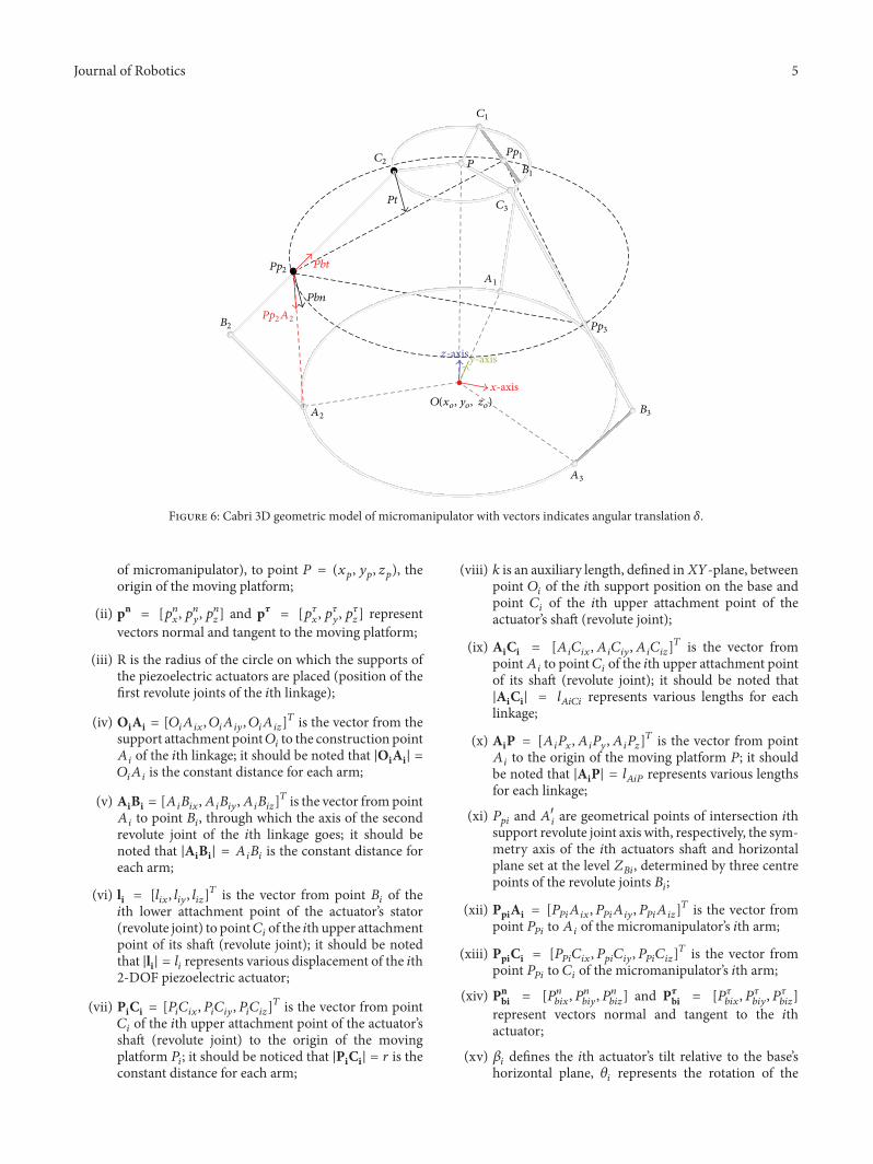
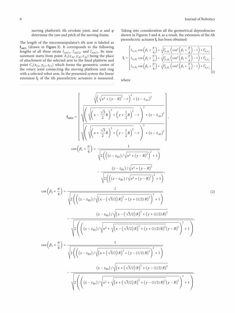


![KINEMATICS - new.excellencia.co.innew.excellencia.co.in/college/web/pdf/Kinematics-merged.pdf · KINEMATICS KINEMATICS WORKSHEET 1 1) Displacement is a _____ [ ] 1) Vector quantity](https://static.documents.pub/doc/80x56/5f356d4687229051801abace/kinematics-new-kinematics-kinematics-worksheet-1-1-displacement-is-a-.jpg)


