Research ArticlePrediction of Collapse Scope of Deep-Buried Tunnels UsingPressure Arch Theory
Yingchao Wang,1,2 Hongwen Jing,1,2 Qiang Zhang,1 Ning Luo,1 and Xin Yin1
1State Key Laboratory for Geomechanics and Deep Underground Engineering, China University of Mining and Technology,Xuzhou, Jiangsu 221116, China2School of Mechanics and Civil Engineering, China University of Mining and Technology, Xuzhou, Jiangsu 221116, China
Correspondence should be addressed to Yingchao Wang; [email protected]
Tunnel collapse remains a serious problem in practice. Effective prediction methods on tunnel collapse are necessary for tunnelengineering. In this study, systematic study on the pressure arch was presented to predict tunnel collapse. Multiple factors underdifferent conditionswere considered. First, the pressure archwas described as a certain scope in comparisonwith the lowest pressurearch line.Then, a deep-buried circular tunnel was selected as the investigated object. Its collapse scopewas analyzed using the lowestpressure arch line. Meanwhile, the main influence from the ground stress field was considered. Different modes of ground stressfields were investigated in detail.The results indicate that the collapse scope varies with different ground stress fields. Determinationon the collapse scope is strongly affected by the judgment standard of the pressure arch. Furthermore, a selected case was analyzedwith the pressure arch. The area and the height of tunnel collapse were calculated with multiple factors, including ground stressfield, judgment standard, and lateral pressure coefficient. Finally, selected results were compared with relevant previous researches,and reasonable results were obtained. The present results are helpful for further understanding of the tunnel collapse and couldprovide suitable guidance for tunnel projects.
1. Introduction
Roof collapse of underground cavities is a practical problemin geotechnical engineering, which usually arises not onlyin shallow tunnels but also in deep-buried tunnels. Recently,deeper and longer tunnels have been constructed or areunder construction in hydropower and transportation fieldsin China [1]. During the construction of deep-buried tunnels,collapse frequently occurs, which leads to great economiclosses and heavy casualties [2–4]. Many efforts have beenmade to prevent deep-buried tunnels fromcollapsing, includ-ing monitoring, measurement, and prediction. Meanwhile,collapse prediction for deep-buried tunnels is imperativeduring tunnel construction.
Deep-buried tunnels present many complicated engi-neering problems [5]. First, tunneling usually traverses mul-tiple geological conditions, like deep underground strataand thick or extremely thick layered rock strata. Second,
the presence of cracks and fractures in rock banks candirectly induce tunnel collapse [3, 6]. Third, tunnel collapseis strongly affected by random variation in the mechanicalproperties of the rock in situ. In addition, tunnel collapsecan be caused not only by these natural factors [7] but alsoby human factors, including blast vibration [8], constructionconditions, support design, and unexpected failures at work.As a result, more and more attention has been paid totunnel collapse, particularly for deep-buried tunnels. In orderto better understand tunnel collapse, much research hasbeen done on estimating the instability of tunnel roofs andheading faces, using several approaches, including numericalsimulation, experimentalmethods, and analytical approaches[9–11]. However, it is difficult to investigate tunnel col-lapse experimentally, since recent measurement techniquesare limited by the multiscale complexity of the system.Numerical simulations are usually accompanied by multipleassumptions with a complex calculation process. Due to its
Hindawi Publishing CorporationMathematical Problems in EngineeringVolume 2016, Article ID 2628174, 10 pageshttp://dx.doi.org/10.1155/2016/2628174
2 Mathematical Problems in Engineering
feasibility and conveniences, the analytical approach has beenwidely employed to estimate the stability problems in tunnelengineering.
Previous studies on tunnel collapse have focused onanalysis techniques, which have been proposed for evaluatingthe stability of tunnels and investigating the so-called archingeffect for both soft soils and hard rocks [12, 13]. Meanwhile,some techniques depended on the specific prepartitioningof the soil domain with theorems of limit analysis [14].Three independent methods were used to evaluate the roofcollapse of underground rectangular cavities for a range ofgeometries and rock properties [15]. Moreover, an analyticalupper bound method, proposed by Fraldi and Guarracino,was used to predict plastic collapse in circular rock tunnels[6, 16]. According to Hoke-Brown failure criterion and theupper bound theorem of limit analysis, tunnel collapseunder seepage forces condition and three-dimensional failuremechanism of a rectangular cavity were studied in detail[9, 17–21]. Senent et al. [22] studied the face stability ofcircular tunnels, which were excavated in heavily fracturedand “low quality” rock masses, and the nonlinear Hoke-Brown (HB) failure criterion was applied. Useful results havebeen obtained with the abovementioned methods. However,due to the complex features of the engineering conditions,it is difficult for one method to obtain useful results whenpredicting collapse position and the collapse height. Inaddition, an accurate method of determining the loadingmode has yet to be found, which should be acknowledgedand could be applied to a wide range of tunnel collapses.Therefore, further research on predicting tunnel collapses isindeed necessary. To estimate the instability of tunnel roofs,a reliable and feasible method is still needed to calculate thecollapse scopemore accurately for deep-buried tunnels underdifferent ground stress fields.
In practice, the main issue faced by engineering is theanalysis of roof failure occurring in deep-buried tunnels [9].It is still difficult to accurately calculate the key parame-ters of pressure in the surrounding rock and the relativearching mechanism is also ambiguous [23]. Meanwhile, theevolution characteristics of the pressure arch for a tunnel aredifficult to determine exactly. Generally, there is a lack oftheoretical solutions, not only for estimating the instabilityof tunnel roof, but also for predicting the scope of collapsefor deep-buried tunnels, especially under different stressfields. However, there are many methods currently beinginvestigated by engineers and researchers, including theanalogue model with experience, the structural-geologicalmodel, the constrainedmodel with convergence, and the loadmodel. The load model is regarded as one of the most usefulmodels for calculating the pressure of the surrounding rockin tunnel engineering. In detail, the load model involves therestrictive effect of upper strata on the surrounding rock,which is regarded as the main effect of the pressure arch.Research on the pressure arch has been conducted for a longtime, but its application is very limited in some conditions.
In the present work, pressure arch theory was employedas an analysis method to predict the collapse scope in deep-buried tunnels. First, the pressure arch derived from pressurearch theory is described in detail. Meanwhile, the lowest
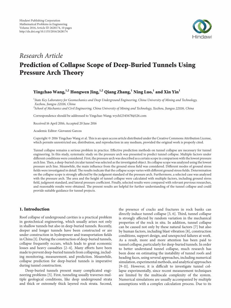
Curve A Curve B
Figure 1: Pressure arch of unexcavated tunnel.
pressure arch curve is presented for prediction. Based onthe lowest pressure arch, the presented pressure arch curvewas applied to predict the collapse scope for a deep-buriedcircular tunnel. Then, the main influences of the groundstress field related to tunnel collapses were investigated.Moreover, the area and the height of the collapse scope werecalculated and analyzed for the deep-buried circular tunnel.Furthermore, multiple factors, including ground stress field,judgment standard, and lateral pressure coefficient, wereconsidered when calculating the area and height of tunnelcollapse to find the tendency and variation. Selected resultsfrom the present study were compared with results obtainedby other researchers. These results are helpful to estimate theoverall burden on the lining and can guide further study ofprediction methods for tunnel collapses.
2. The Pressure Arch Theory
The present pressure arch was derived from pressure archtheory but differs from that theory in key ways, which aredescribed as follows.
Before the tunnel excavation, all the surrounding rockwas under pressure due to the action of gravity. Thus, thesurrounding rock along any inner curvewas in a compressionstate along three axes, known as the triaxial compressionstate, as shown in Figure 1. For example, A and B are arbitrarycurves of the pressure arch, which are stable.
After tunnel excavation, due to the unloading effect, thestress in the surrounding rock around the tunnel contourchanges, and the surrounding rock within different scopesmight have different stress levels. Thus, there is no guaranteethat the surrounding rock along any arbitrary curve is in acompression state.There should be some surrounding rock ina tensile state with different tensile stress levels. Meanwhile,there exists a curve with a tensile stress of zero. This curveis used for partitioning the region of the surrounding rockabove the tunnel contour, which can be divided into twomainregions.
Above the curve with a tensile stress of zero, the sur-rounding rock within a certain scope is thought to be inthe unidirectional compression state, which seems like anarch and is defined as the pressure arch in the present study.Furthermore, the curve with a tensile stress of zero is selectedas the lowest pressure arch curve. Any arbitrary curve abovethe lowest pressure arch curve, like A in Figure 1, is called thepressure arch. On the pressure arch curve, the surroundingrock is still in a compression state, as shown in Figure 2.
Mathematical Problems in Engineering 3
Curve A The lowestpressure arch line
Tunnel
Tunnel contour
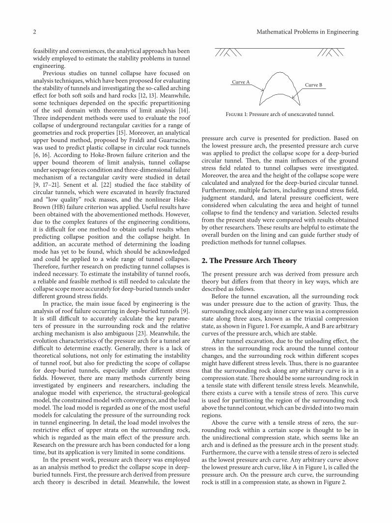
Figure 2: Pressure arch of excavated tunnel.
On the other hand, below the lowest pressure arch line,the surrounding rock within a limited scope above the tunnelcontour is in a tension state with instability, since the tensilebearing capacity is low for the cracked surrounding rock.Theunstable state of the surrounding rock could cause collapse-induced damage and lead to tunnel collapse. The scope ofinstability within the surrounding rock is regarded as thecollapse scope in the present study.
According to the abovementioned analysis, the lowestpressure arch line is significant for predicting collapse of thesurrounding rock, which should be gained in the first place.Then, the collapse would be gained accordingly when the areaand the height of collapse scope for tunnels are obtained.
3. Results and Discussion
3.1. The Pressure Arch with Bidirectional andConstant Ground Stress
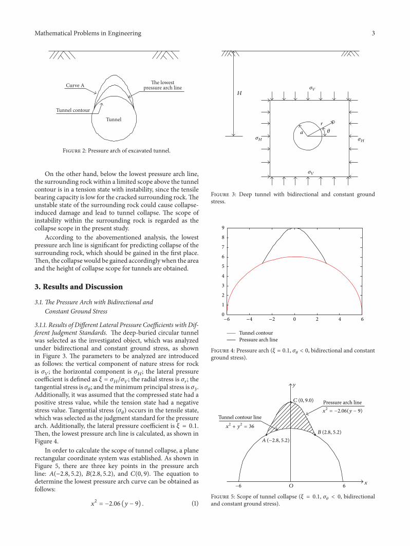
3.1.1. Results of Different Lateral Pressure Coefficients with Dif-ferent Judgment Standards. The deep-buried circular tunnelwas selected as the investigated object, which was analyzedunder bidirectional and constant ground stress, as shownin Figure 3. The parameters to be analyzed are introducedas follows: the vertical component of nature stress for rockis 𝜎𝑉; the horizontal component is 𝜎
𝐻; the lateral pressure
coefficient is defined as 𝜉 = 𝜎𝐻/𝜎𝑉; the radial stress is 𝜎
𝑟; the
tangential stress is 𝜎𝜃; and theminimumprincipal stress is 𝜎
3.
Additionally, it was assumed that the compressed state had apositive stress value, while the tension state had a negativestress value. Tangential stress (𝜎
𝜃) occurs in the tensile state,
which was selected as the judgment standard for the pressurearch. Additionally, the lateral pressure coefficient is 𝜉 = 0.1.Then, the lowest pressure arch line is calculated, as shown inFigure 4.
In order to calculate the scope of tunnel collapse, a planerectangular coordinate system was established. As shown inFigure 5, there are three key points in the pressure archline: 𝐴(−2.8, 5.2), 𝐵(2.8, 5.2), and 𝐶(0, 9). The equation todetermine the lowest pressure arch curve can be obtained asfollows:
𝑥2= −2.06 (𝑦 − 9) . (1)
H𝜎V
𝜎V
𝜎H 𝜎H
𝜃a
r
Figure 3: Deep tunnel with bidirectional and constant groundstress.
Equation (1) can also be expressed as 𝑦1= −𝑥2/2.06 + 9,
while the equation to determine the tunnel contour curve ispresented as
𝑥2+ 𝑦2= 36. (2)
Meanwhile, (2) can also be expressed as 𝑦2= √36 − 𝑥
2.Therefore, the scope of tunnel collapse can be calculated
as follows:
𝑆 = ∫
2.8
−2.8
(𝑦1− 𝑦2) 𝑑𝑥
= ∫
2.8
−2.8
(−
𝑥2
2.06
+ 9 − √36 − 𝑥2)𝑑𝑥 = 10.96m2.
(3)
Accordingly, the average height of tunnel collapse can becalculated as follows:
ℎavg =10.96m2
5.6m= 1.96m. (4)
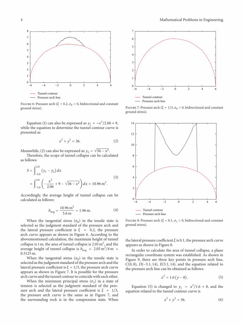
When the tangential stress (𝜎𝜃) in the tensile state is
selected as the judgment standard of the pressure arch andthe lateral pressure coefficient is 𝜉 = 0.2, the pressurearch curve appears as shown in Figure 6. According to theabovementioned calculation, the maximum height of tunnelcollapse is 1m, the area of tunnel collapse is 2.05m2, and theaverage height of tunnel collapse is ℎavg = 2.05m2/4m =
0.5125m.When the tangential stress (𝜎
𝜃) in the tensile state is
selected as the judgment standard of the pressure arch and thelateral pressure coefficient is 𝜉 = 1/3, the pressure arch curveappears as shown in Figure 7. It is possible for the pressurearch curve and the tunnel contour to coincidewith each other.
When the minimum principal stress (𝜎3) in a state of
tension is selected as the judgment standard of the pres-sure arch and the lateral pressure coefficient is 𝜉 = 1/3,the pressure arch curve is the same as in Figure 7, andthe surrounding rock is in the compression state. When
the lateral pressure coefficient 𝜉 is 0.1, the pressure arch curveappears as shown in Figure 8.
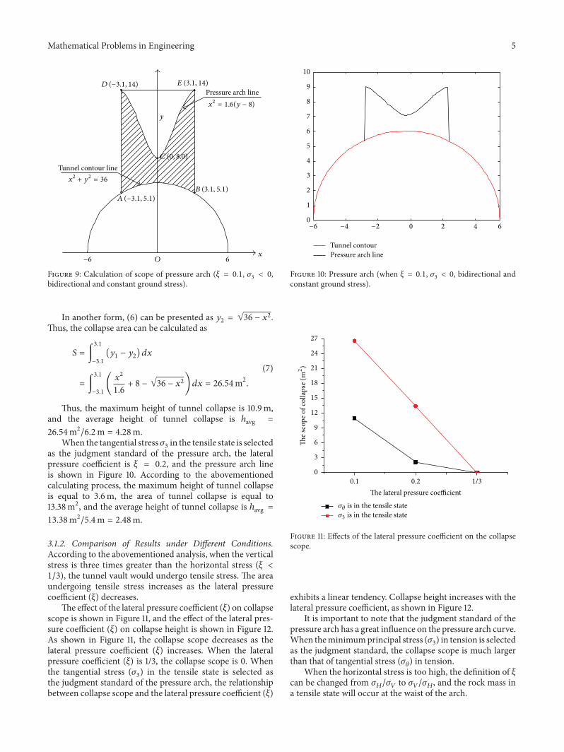
In order to calculate the area of tunnel collapse, a planerectangular coordinate system was established. As shown inFigure 9, there are three key points in pressure arch line,𝐶(0, 8), 𝐷(−3.1, 14), 𝐸(3.1, 14), and the equation related tothe pressure arch line can be obtained as follows:
𝑥2= 1.6 (𝑦 − 8) . (5)
Equation (5) is changed to 𝑦1
= 𝑥2/1.6 + 8, and the
equation related to the tunnel contour curve is
𝑥2+ 𝑦2= 36. (6)
Mathematical Problems in Engineering 5
Tunnel contour line
x
y
6
Pressure arch line
−6 O
x2 + y2 = 36
x2 = 1.6(y − 8)
C (0, 8.0)
B (3.1, 5.1)A (−3.1, 5.1)
E (3.1, 14)D (−3.1, 14)
Figure 9: Calculation of scope of pressure arch (𝜉 = 0.1, 𝜎3< 0,
bidirectional and constant ground stress).
In another form, (6) can be presented as 𝑦2= √36 − 𝑥
2.Thus, the collapse area can be calculated as
𝑆 = ∫
3.1
−3.1
(𝑦1− 𝑦2) 𝑑𝑥
= ∫
3.1
−3.1
(
𝑥2
1.6
+ 8 − √36 − 𝑥2)𝑑𝑥 = 26.54m2.
(7)
Thus, the maximum height of tunnel collapse is 10.9m,and the average height of tunnel collapse is ℎavg =
26.54m2/6.2m = 4.28m.When the tangential stress𝜎
3in the tensile state is selected
as the judgment standard of the pressure arch, the lateralpressure coefficient is 𝜉 = 0.2, and the pressure arch lineis shown in Figure 10. According to the abovementionedcalculating process, the maximum height of tunnel collapseis equal to 3.6m, the area of tunnel collapse is equal to13.38m2, and the average height of tunnel collapse is ℎavg =
13.38m2/5.4m = 2.48m.
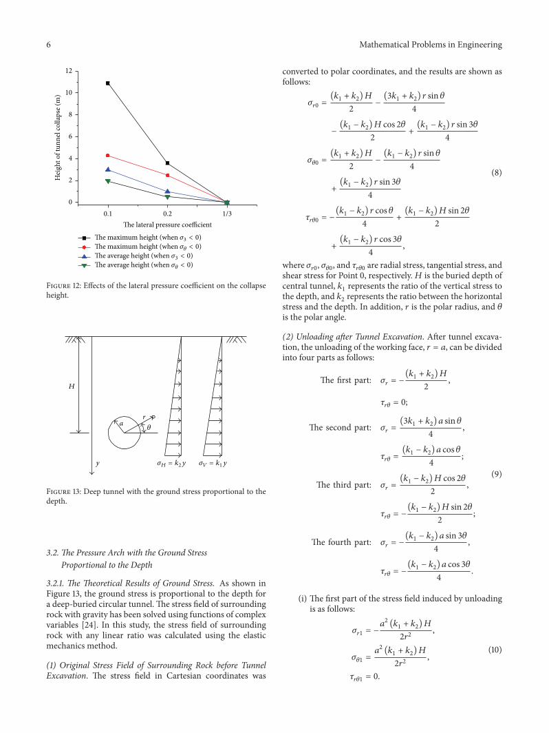
3.1.2. Comparison of Results under Different Conditions.According to the abovementioned analysis, when the verticalstress is three times greater than the horizontal stress (𝜉 <
1/3), the tunnel vault would undergo tensile stress. The areaundergoing tensile stress increases as the lateral pressurecoefficient (𝜉) decreases.
The effect of the lateral pressure coefficient (𝜉) on collapsescope is shown in Figure 11, and the effect of the lateral pres-sure coefficient (𝜉) on collapse height is shown in Figure 12.As shown in Figure 11, the collapse scope decreases as thelateral pressure coefficient (𝜉) increases. When the lateralpressure coefficient (𝜉) is 1/3, the collapse scope is 0. Whenthe tangential stress (𝜎
3) in the tensile state is selected as
the judgment standard of the pressure arch, the relationshipbetween collapse scope and the lateral pressure coefficient (𝜉)
𝜎3 is in the tensile state𝜎𝜃 is in the tensile state
0
3
6
9
12
15
18
21
24
27
The s
cope
of c
ollap
se (m
2)
Figure 11: Effects of the lateral pressure coefficient on the collapsescope.
exhibits a linear tendency. Collapse height increases with thelateral pressure coefficient, as shown in Figure 12.
It is important to note that the judgment standard of thepressure arch has a great influence on the pressure arch curve.When theminimumprincipal stress (𝜎
3) in tension is selected
as the judgment standard, the collapse scope is much largerthan that of tangential stress (𝜎
𝜃) in tension.
When the horizontal stress is too high, the definition of 𝜉can be changed from 𝜎
𝐻/𝜎𝑉to 𝜎𝑉/𝜎𝐻, and the rock mass in
a tensile state will occur at the waist of the arch.
6 Mathematical Problems in Engineering
0
2
4
6
8
10
12
Hei
ght o
f tun
nel c
ollap
se (m
)
0.1 1/30.2The lateral pressure coefficient
The maximum height (when 𝜎3 < 0)The maximum height (when 𝜎𝜃 < 0)The average height (when 𝜎3 < 0)The average height (when 𝜎𝜃 < 0)
Figure 12: Effects of the lateral pressure coefficient on the collapseheight.
H
𝜎H = k2y 𝜎V = k1yy
ra
𝜃
Figure 13: Deep tunnel with the ground stress proportional to thedepth.
3.2. The Pressure Arch with the Ground StressProportional to the Depth
3.2.1. The Theoretical Results of Ground Stress. As shown inFigure 13, the ground stress is proportional to the depth fora deep-buried circular tunnel. The stress field of surroundingrock with gravity has been solved using functions of complexvariables [24]. In this study, the stress field of surroundingrock with any linear ratio was calculated using the elasticmechanics method.
(1) Original Stress Field of Surrounding Rock before TunnelExcavation. The stress field in Cartesian coordinates was
converted to polar coordinates, and the results are shown asfollows:
𝜎𝑟0=
(𝑘1+ 𝑘2)𝐻
2
−
(3𝑘1+ 𝑘2) 𝑟 sin 𝜃
4
−
(𝑘1− 𝑘2)𝐻 cos 2𝜃2
+
(𝑘1− 𝑘2) 𝑟 sin 3𝜃4
𝜎𝜃0
=
(𝑘1+ 𝑘2)𝐻
2
−
(𝑘1− 𝑘2) 𝑟 sin 𝜃4
+
(𝑘1− 𝑘2) 𝑟 sin 3𝜃4
𝜏𝑟𝜃0
= −
(𝑘1− 𝑘2) 𝑟 cos 𝜃4
+
(𝑘1− 𝑘2)𝐻 sin 2𝜃2
+
(𝑘1− 𝑘2) 𝑟 cos 3𝜃4
,
(8)
where 𝜎𝑟0, 𝜎𝜃0, and 𝜏
𝑟𝜃0are radial stress, tangential stress, and
shear stress for Point 0, respectively.𝐻 is the buried depth ofcentral tunnel, 𝑘
1represents the ratio of the vertical stress to
the depth, and 𝑘2represents the ratio between the horizontal
stress and the depth. In addition, 𝑟 is the polar radius, and 𝜃
is the polar angle.
(2) Unloading after Tunnel Excavation. After tunnel excava-tion, the unloading of the working face, 𝑟 = 𝑎, can be dividedinto four parts as follows:
The first part: 𝜎𝑟= −
(𝑘1+ 𝑘2)𝐻
2
,
𝜏𝑟𝜃= 0;
The second part: 𝜎𝑟=
(3𝑘1+ 𝑘2) 𝑎 sin 𝜃
4
,
𝜏𝑟𝜃=
(𝑘1− 𝑘2) 𝑎 cos 𝜃4
;
The third part: 𝜎𝑟=
(𝑘1− 𝑘2)𝐻 cos 2𝜃2
,
𝜏𝑟𝜃= −
(𝑘1− 𝑘2)𝐻 sin 2𝜃2
;
The fourth part: 𝜎𝑟= −
(𝑘1− 𝑘2) 𝑎 sin 3𝜃4
,
𝜏𝑟𝜃= −
(𝑘1− 𝑘2) 𝑎 cos 3𝜃4
.
(9)
(i) The first part of the stress field induced by unloadingis as follows:
𝜎𝑟1= −
𝑎2(𝑘1+ 𝑘2)𝐻
2𝑟2
,
𝜎𝜃1
=
𝑎2(𝑘1+ 𝑘2)𝐻
2𝑟2
,
𝜏𝑟𝜃1
= 0.
(10)
Mathematical Problems in Engineering 7
(ii) The second part of the stress field induced by unload-ing is as follows:
𝜎𝑟2= {
(3 + 𝜇) 𝑘1𝑎2
4𝑟
+
(𝑘2− 𝜇𝑘1) 𝑎4
4𝑟3
} sin 𝜃,
𝜎𝜃2
= {−
(1 − 𝜇) 𝑘1𝑎2
4𝑟
−
(𝑘2− 𝜇𝑘1) 𝑎4
4𝑟3
} sin 𝜃,
𝜏𝑟𝜃2
= {
(1 − 𝜇) 𝑘1𝑎2
4𝑟
−
(𝑘2− 𝜇𝑘1) 𝑎4
4𝑟3
} cos 𝜃.
(11)
(iii) The third part of the stress field induced by unloadingis as follows:
𝜎𝑟3= [
2 (𝑘1− 𝑘2)𝐻𝑎2
𝑟2
−
3 (𝑘1− 𝑘2)𝐻𝑎4
2𝑟4
] cos 2𝜃,
𝜎𝜃3
=
3 (𝑘1− 𝑘2)𝐻𝑎4
2𝑟4
cos 2𝜃,
𝜏𝑟𝜃3
= [
(𝑘1− 𝑘2)𝐻𝑎2
𝑟2
−
3 (𝑘1− 𝑘2)𝐻𝑎4
2𝑟4
] sin 2𝜃.
(12)
(iv) The fourth part of the stress field induced by unload-ing is as follows:
𝜎𝑟4= [−
5 (𝑘1− 𝑘2) 𝑎4
4𝑟3
+
(𝑘1− 𝑘2) 𝑎6
𝑟5
] sin 3𝜃,
𝜎𝜃4
= [
(𝑘1− 𝑘2) 𝑎4
4𝑟3
−
(𝑘1− 𝑘2) 𝑎6
𝑟5
] sin 3𝜃,
𝜏𝑟𝜃4
= [
3 (𝑘1− 𝑘2) 𝑎4
4𝑟3
−
(𝑘1− 𝑘2) 𝑎6
𝑟5
] cos 3𝜃.
(13)
(3) The Total Stress Field of Surrounding Rock after TunnelExcavation. The original stress field and the stress fieldinduced by unloading can be added, and the total stress fieldafter excavation can be obtained as follows:
𝜎𝑟= 𝜎𝑟0+ 𝜎𝑟1+ 𝜎𝑟2+ 𝜎𝑟3+ 𝜎𝑟4,
𝜎𝜃= 𝜎𝜃0+ 𝜎𝜃1+ 𝜎𝜃2+ 𝜎𝜃3+ 𝜎𝜃4,
𝜏𝑟𝜃= 𝜏𝑟𝜃0
+ 𝜏𝑟𝜃1
+ 𝜏𝑟𝜃2
+ 𝜏𝑟𝜃3
+ 𝜏𝑟𝜃4
.
(14)
3.2.2. Case Study. In order to analyze the pressure archin detail, a deep-buried circular tunnel was selected as anexample. For the tunnel, the buried depth 𝐻 was 600m, theradius was 6m, and the rock mass density 𝛾 was 25 kN/m3(𝑘2= 25 kN/m3). The coefficients of lateral pressure with
respect to 𝑘1and 𝑘
2were assigned values of 0.1 and 0.2,
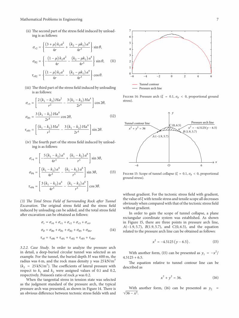
respectively. Poisson’s ratio of rock 𝜇 was 0.2.When the tangential stress in tension state was selected
as the judgment standard of the pressure arch, the typicalpressure arch was presented, as shown in Figure 14. There isan obvious difference between tectonic stress fields with and
without gradient. For the tectonic stress field with gradient,the value of 𝜉with tensile stress and tensile scope all decreasesobviously when comparedwith that of the tectonic stress fieldwithout gradient.
In order to gain the scope of tunnel collapse, a planerectangular coordinate system was established. As shownin Figure 15, there are three points in pressure arch line,𝐴(−1.9, 5.7), 𝐵(1.9, 5.7), and 𝐶(0, 6.5), and the equationrelated to the pressure arch line can be obtained as follows:
𝑥2= −4.5125 (𝑦 − 6.5) . (15)
With another form, (15) can be presented as 𝑦1= −𝑥2/
4.5125 + 6.5.The equation relative to tunnel contour line can be
Then, the area of tunnel collapse can be calculated as
𝑆 = ∫
1.9
−1.9
(𝑦1− 𝑦2) 𝑑𝑥
= ∫
1.9
−1.9
(−
𝑥2
4.5125
+ 6.5 − √36 − 𝑥2)𝑑𝑥 = 1.27m2.
(17)
Therefore, themaximumheight of tunnel collapse is equalto 0.5m, the area is equal to 1.27m2, and the average heightof tunnel collapse is ℎavg = 1.27m2/3.8m = 0.33m.
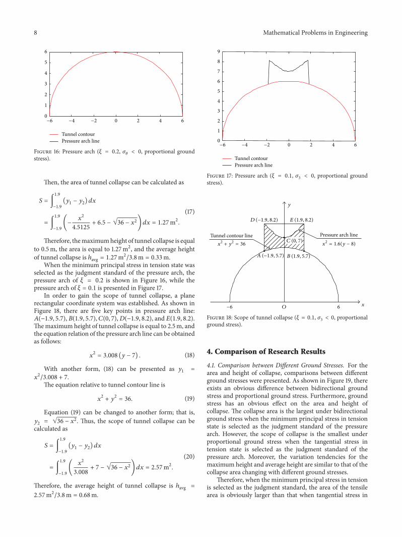
When the minimum principal stress in tension state wasselected as the judgment standard of the pressure arch, thepressure arch of 𝜉 = 0.2 is shown in Figure 16, while thepressure arch of 𝜉 = 0.1 is presented in Figure 17.
In order to gain the scope of tunnel collapse, a planerectangular coordinate system was established. As shown inFigure 18, there are five key points in pressure arch line:𝐴(−1.9, 5.7), 𝐵(1.9, 5.7), 𝐶(0, 7),𝐷(−1.9, 8.2), and 𝐸(1.9, 8.2).Themaximum height of tunnel collapse is equal to 2.5m, andthe equation relation of the pressure arch line can be obtainedas follows:
𝑥2= 3.008 (𝑦 − 7) . (18)
With another form, (18) can be presented as 𝑦1
=
𝑥2/3.008 + 7.The equation relative to tunnel contour line is
𝑥2+ 𝑦2= 36. (19)
Equation (19) can be changed to another form; that is,𝑦2= √36 − 𝑥
2. Thus, the scope of tunnel collapse can becalculated as
𝑆 = ∫
1.9
−1.9
(𝑦1− 𝑦2) 𝑑𝑥
= ∫
1.9
−1.9
(
𝑥2
3.008
+ 7 − √36 − 𝑥2)𝑑𝑥 = 2.57m2.
(20)
Therefore, the average height of tunnel collapse is ℎavg =
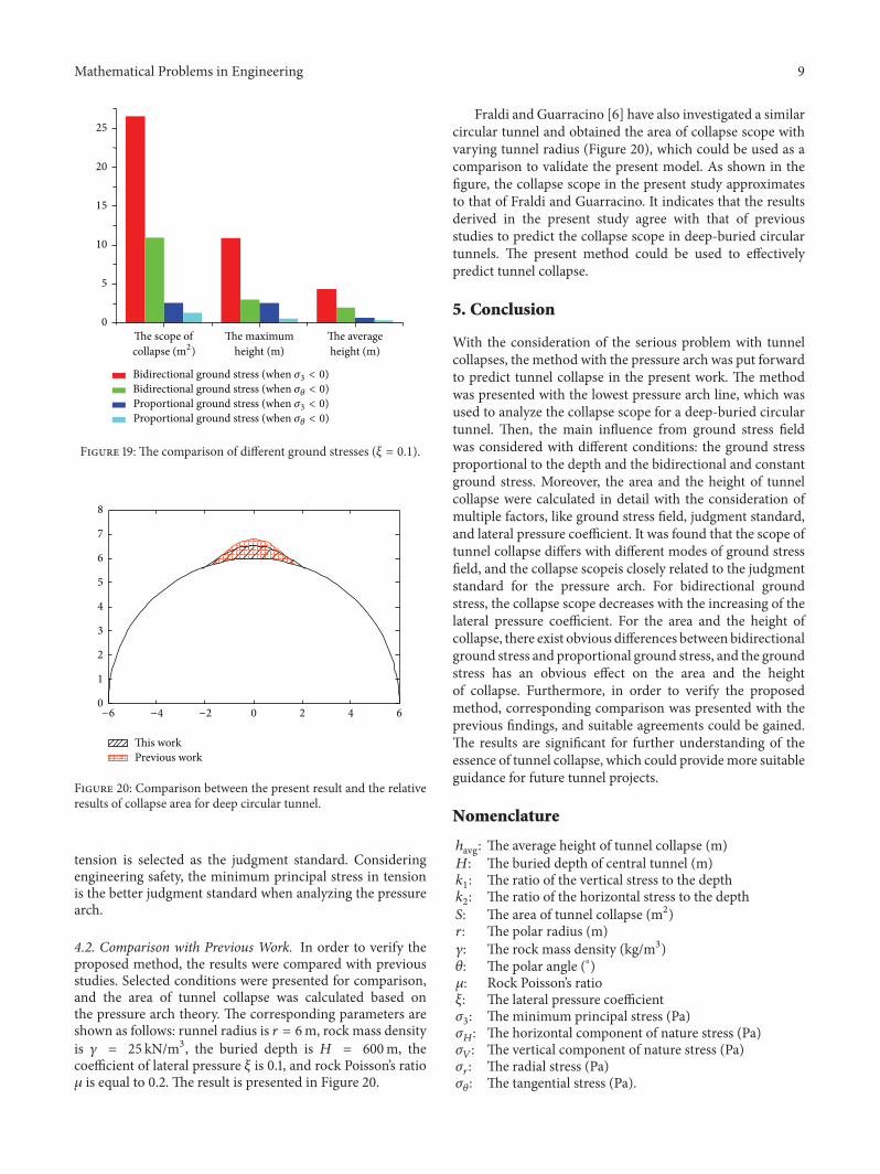
4.1. Comparison between Different Ground Stresses. For thearea and height of collapse, comparisons between differentground stresses were presented. As shown in Figure 19, thereexists an obvious difference between bidirectional groundstress and proportional ground stress. Furthermore, groundstress has an obvious effect on the area and height ofcollapse. The collapse area is the largest under bidirectionalground stress when the minimum principal stress in tensionstate is selected as the judgment standard of the pressurearch. However, the scope of collapse is the smallest underproportional ground stress when the tangential stress intension state is selected as the judgment standard of thepressure arch. Moreover, the variation tendencies for themaximum height and average height are similar to that of thecollapse area changing with different ground stresses.
Therefore, when the minimum principal stress in tensionis selected as the judgment standard, the area of the tensilearea is obviously larger than that when tangential stress in
Figure 19: The comparison of different ground stresses (𝜉 = 0.1).
This workPrevious work
0
1
2
3
4
5
6
7
8
−4 −2 0 2 4 6−6
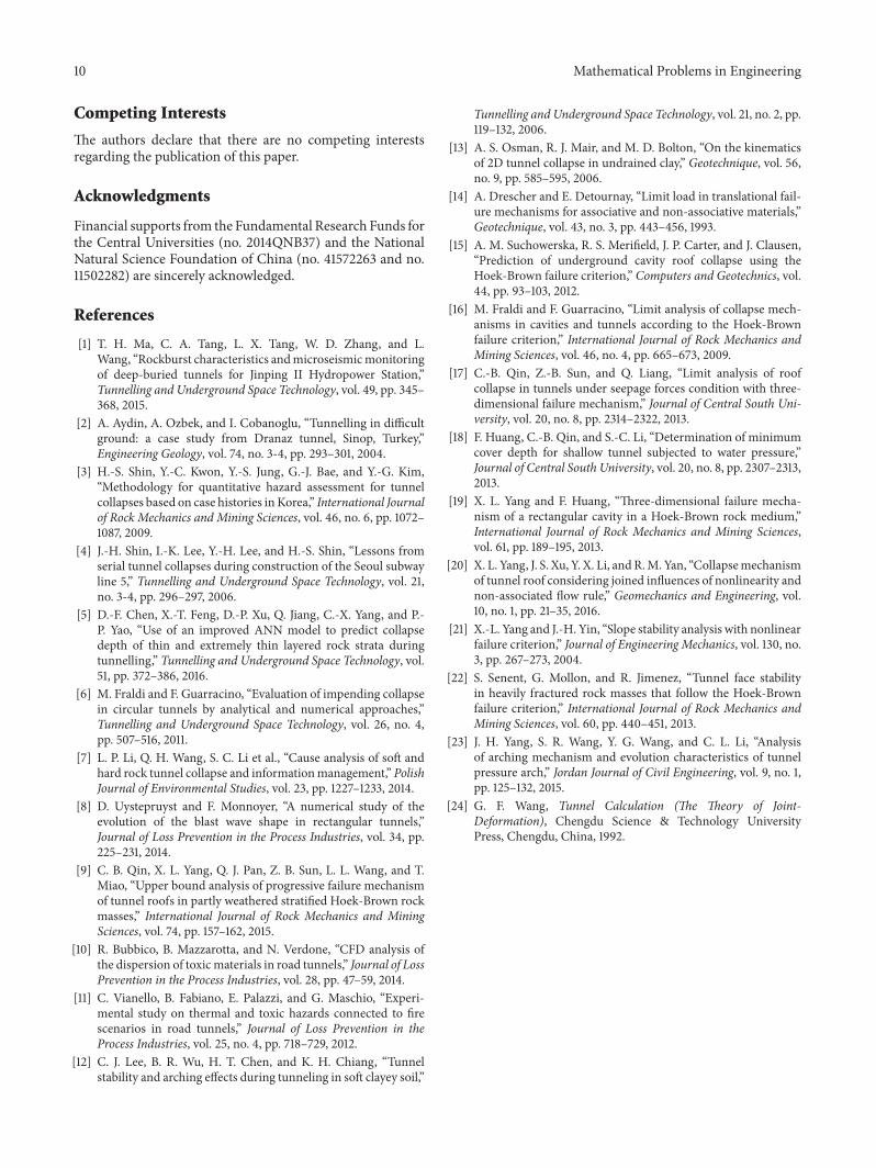
Figure 20: Comparison between the present result and the relativeresults of collapse area for deep circular tunnel.
tension is selected as the judgment standard. Consideringengineering safety, the minimum principal stress in tensionis the better judgment standard when analyzing the pressurearch.
4.2. Comparison with Previous Work. In order to verify theproposed method, the results were compared with previousstudies. Selected conditions were presented for comparison,and the area of tunnel collapse was calculated based onthe pressure arch theory. The corresponding parameters areshown as follows: runnel radius is 𝑟 = 6m, rock mass densityis 𝛾 = 25 kN/m3, the buried depth is 𝐻 = 600m, thecoefficient of lateral pressure 𝜉 is 0.1, and rock Poisson’s ratio𝜇 is equal to 0.2. The result is presented in Figure 20.
Fraldi and Guarracino [6] have also investigated a similarcircular tunnel and obtained the area of collapse scope withvarying tunnel radius (Figure 20), which could be used as acomparison to validate the present model. As shown in thefigure, the collapse scope in the present study approximatesto that of Fraldi and Guarracino. It indicates that the resultsderived in the present study agree with that of previousstudies to predict the collapse scope in deep-buried circulartunnels. The present method could be used to effectivelypredict tunnel collapse.
5. Conclusion
With the consideration of the serious problem with tunnelcollapses, the method with the pressure arch was put forwardto predict tunnel collapse in the present work. The methodwas presented with the lowest pressure arch line, which wasused to analyze the collapse scope for a deep-buried circulartunnel. Then, the main influence from ground stress fieldwas considered with different conditions: the ground stressproportional to the depth and the bidirectional and constantground stress. Moreover, the area and the height of tunnelcollapse were calculated in detail with the consideration ofmultiple factors, like ground stress field, judgment standard,and lateral pressure coefficient. It was found that the scope oftunnel collapse differs with different modes of ground stressfield, and the collapse scopeis closely related to the judgmentstandard for the pressure arch. For bidirectional groundstress, the collapse scope decreases with the increasing of thelateral pressure coefficient. For the area and the height ofcollapse, there exist obvious differences between bidirectionalground stress and proportional ground stress, and the groundstress has an obvious effect on the area and the heightof collapse. Furthermore, in order to verify the proposedmethod, corresponding comparison was presented with theprevious findings, and suitable agreements could be gained.The results are significant for further understanding of theessence of tunnel collapse, which could providemore suitableguidance for future tunnel projects.
Nomenclature
ℎavg: The average height of tunnel collapse (m)𝐻: The buried depth of central tunnel (m)𝑘1: The ratio of the vertical stress to the depth
𝑘2: The ratio of the horizontal stress to the depth
𝑆: The area of tunnel collapse (m2)𝑟: The polar radius (m)𝛾: The rock mass density (kg/m3)𝜃: The polar angle (∘)𝜇: Rock Poisson’s ratio𝜉: The lateral pressure coefficient𝜎3: The minimum principal stress (Pa)
𝜎𝐻: The horizontal component of nature stress (Pa)
𝜎𝑉: The vertical component of nature stress (Pa)
𝜎𝑟: The radial stress (Pa)
𝜎𝜃: The tangential stress (Pa).
10 Mathematical Problems in Engineering
Competing Interests
The authors declare that there are no competing interestsregarding the publication of this paper.
Acknowledgments
Financial supports from the Fundamental Research Funds forthe Central Universities (no. 2014QNB37) and the NationalNatural Science Foundation of China (no. 41572263 and no.11502282) are sincerely acknowledged.
References
[1] T. H. Ma, C. A. Tang, L. X. Tang, W. D. Zhang, and L.Wang, “Rockburst characteristics andmicroseismicmonitoringof deep-buried tunnels for Jinping II Hydropower Station,”Tunnelling and Underground Space Technology, vol. 49, pp. 345–368, 2015.
[2] A. Aydin, A. Ozbek, and I. Cobanoglu, “Tunnelling in difficultground: a case study from Dranaz tunnel, Sinop, Turkey,”Engineering Geology, vol. 74, no. 3-4, pp. 293–301, 2004.
[3] H.-S. Shin, Y.-C. Kwon, Y.-S. Jung, G.-J. Bae, and Y.-G. Kim,“Methodology for quantitative hazard assessment for tunnelcollapses based on case histories in Korea,” International Journalof Rock Mechanics and Mining Sciences, vol. 46, no. 6, pp. 1072–1087, 2009.
[4] J.-H. Shin, I.-K. Lee, Y.-H. Lee, and H.-S. Shin, “Lessons fromserial tunnel collapses during construction of the Seoul subwayline 5,” Tunnelling and Underground Space Technology, vol. 21,no. 3-4, pp. 296–297, 2006.
[5] D.-F. Chen, X.-T. Feng, D.-P. Xu, Q. Jiang, C.-X. Yang, and P.-P. Yao, “Use of an improved ANN model to predict collapsedepth of thin and extremely thin layered rock strata duringtunnelling,” Tunnelling and Underground Space Technology, vol.51, pp. 372–386, 2016.
[6] M. Fraldi and F. Guarracino, “Evaluation of impending collapsein circular tunnels by analytical and numerical approaches,”Tunnelling and Underground Space Technology, vol. 26, no. 4,pp. 507–516, 2011.
[7] L. P. Li, Q. H. Wang, S. C. Li et al., “Cause analysis of soft andhard rock tunnel collapse and informationmanagement,” PolishJournal of Environmental Studies, vol. 23, pp. 1227–1233, 2014.
[8] D. Uystepruyst and F. Monnoyer, “A numerical study of theevolution of the blast wave shape in rectangular tunnels,”Journal of Loss Prevention in the Process Industries, vol. 34, pp.225–231, 2014.
[9] C. B. Qin, X. L. Yang, Q. J. Pan, Z. B. Sun, L. L. Wang, and T.Miao, “Upper bound analysis of progressive failure mechanismof tunnel roofs in partly weathered stratified Hoek-Brown rockmasses,” International Journal of Rock Mechanics and MiningSciences, vol. 74, pp. 157–162, 2015.
[10] R. Bubbico, B. Mazzarotta, and N. Verdone, “CFD analysis ofthe dispersion of toxicmaterials in road tunnels,” Journal of LossPrevention in the Process Industries, vol. 28, pp. 47–59, 2014.
[11] C. Vianello, B. Fabiano, E. Palazzi, and G. Maschio, “Experi-mental study on thermal and toxic hazards connected to firescenarios in road tunnels,” Journal of Loss Prevention in theProcess Industries, vol. 25, no. 4, pp. 718–729, 2012.
[12] C. J. Lee, B. R. Wu, H. T. Chen, and K. H. Chiang, “Tunnelstability and arching effects during tunneling in soft clayey soil,”
Tunnelling and Underground Space Technology, vol. 21, no. 2, pp.119–132, 2006.
[13] A. S. Osman, R. J. Mair, and M. D. Bolton, “On the kinematicsof 2D tunnel collapse in undrained clay,” Geotechnique, vol. 56,no. 9, pp. 585–595, 2006.
[14] A. Drescher and E. Detournay, “Limit load in translational fail-ure mechanisms for associative and non-associative materials,”Geotechnique, vol. 43, no. 3, pp. 443–456, 1993.
[15] A. M. Suchowerska, R. S. Merifield, J. P. Carter, and J. Clausen,“Prediction of underground cavity roof collapse using theHoek-Brown failure criterion,” Computers and Geotechnics, vol.44, pp. 93–103, 2012.
[16] M. Fraldi and F. Guarracino, “Limit analysis of collapse mech-anisms in cavities and tunnels according to the Hoek-Brownfailure criterion,” International Journal of Rock Mechanics andMining Sciences, vol. 46, no. 4, pp. 665–673, 2009.
[17] C.-B. Qin, Z.-B. Sun, and Q. Liang, “Limit analysis of roofcollapse in tunnels under seepage forces condition with three-dimensional failure mechanism,” Journal of Central South Uni-versity, vol. 20, no. 8, pp. 2314–2322, 2013.
[18] F. Huang, C.-B. Qin, and S.-C. Li, “Determination of minimumcover depth for shallow tunnel subjected to water pressure,”Journal of Central South University, vol. 20, no. 8, pp. 2307–2313,2013.
[19] X. L. Yang and F. Huang, “Three-dimensional failure mecha-nism of a rectangular cavity in a Hoek-Brown rock medium,”International Journal of Rock Mechanics and Mining Sciences,vol. 61, pp. 189–195, 2013.
[20] X. L. Yang, J. S. Xu, Y. X. Li, andR.M. Yan, “Collapsemechanismof tunnel roof considering joined influences of nonlinearity andnon-associated flow rule,” Geomechanics and Engineering, vol.10, no. 1, pp. 21–35, 2016.
[21] X.-L. Yang and J.-H. Yin, “Slope stability analysis with nonlinearfailure criterion,” Journal of Engineering Mechanics, vol. 130, no.3, pp. 267–273, 2004.
[22] S. Senent, G. Mollon, and R. Jimenez, “Tunnel face stabilityin heavily fractured rock masses that follow the Hoek-Brownfailure criterion,” International Journal of Rock Mechanics andMining Sciences, vol. 60, pp. 440–451, 2013.
[23] J. H. Yang, S. R. Wang, Y. G. Wang, and C. L. Li, “Analysisof arching mechanism and evolution characteristics of tunnelpressure arch,” Jordan Journal of Civil Engineering, vol. 9, no. 1,pp. 125–132, 2015.
[24] G. F. Wang, Tunnel Calculation (The Theory of Joint-Deformation), Chengdu Science & Technology UniversityPress, Chengdu, China, 1992.