INTRODUCTIONNumerous investigations have shown that trees, crops and otherplants often uproot or snap when they are forced by strong gustsof wind (Baker, 1995; Blackburn et al., 1988; Kerzenmacher andGardiner, 1998). Similarly, Denny et al. (Denny et al., 1998)described how dynamic forces produced by waves are significantto the mechanical stability of the benthic organisms. Because theability to withstand aerodynamic and hydrodynamic forces isimportant to the survival of many plants, a number ofmorphological and structural adaptations have evolved to mitigatethe resulting mechanical stresses (Miller, 2005; Niklas, 1992a;Niklas, 1992b; Vincent, 1990; de Langre, 2008). The remarkableability of plants to withstand extreme forces has generated a greatdeal of interest in the fields of comparative biomechanics, fluiddynamics and biologically inspired design (Alben et al., 2002; deLangre, 2008; Niklas, 1999; Speck and Burgert, 2011; Steinberg,2002; Theckes et al., 2011). Because plant tissues generally havecomplex material properties, translating their design into manmadematerials or mathematical models is not straightforward.Experiments with simplified physical and mathematical modelshave been used to elucidate the mechanical and morphologicalproperties of plants that are fundamental to surviving extremeenvironments.
Plants use flexibility as one strategy to reduce the drag actingupon them while simultaneously avoiding for the most part thesignificant vortex-induced vibrations observed in simple flexible
objects such as flags and banners. Vogel (Vogel, 1989) was the firstto provide data on drag reduction due to flexibility in broad leaves.He found that single broad leaves reconfigure at high flow velocitiesinto cone shapes that reduce flutter and drag when compared withpaper cut-outs of similar shape and flexibility. At the larger scale,he also noticed that leaf clusters and leaflets tend to reconfigureinto larger drag-reducing structures and speculated that similarphenomena are also true for groups of branches. If FD is the dragacting on the leaf or bluff body, then the typical relationship betweendrag and velocity is given as:
where is the density of the fluid, U is the fluid velocity, S is theprojected planar area of one side of the leaf (not taking into accountreconfiguration) and CD is the drag coefficient. Vogel (Vogel, 1989)then considered the effect of reconfiguration using the followingrelationship:
where is the exponent to which the speed must be raised to bedirectly proportional to the drag force divided by the square of speed.The average value of for eight tree species was –0.71. Vogel(Vogel, 2006) later found that a similar phenomenon occurs in waterfor herbaceous plants and proposed that this mechanism increases
= ρF C SU12
, (1)D D2
∝ βFU
U , (2)D
2
SUMMARYFlexible plants, fungi and sessile animals reconfigure in wind and water to reduce the drag acting upon them. In strong winds andflood waters, for example, leaves roll up into cone shapes that reduce drag compared with rigid objects of similar surface area.Less understood is how a leaf attached to a flexible leaf stalk will roll up stably in an unsteady flow. Previous mathematical andphysical models have only considered the case of a flexible sheet attached to a rigid tether in steady flow. In this paper, thedynamics of the flow around the leaf of the wild ginger Hexastylis arifolia and the wild violet Viola papilionacea are describedusing particle image velocimetry. The flows around the leaves are compared with those of simplified physical and numericalmodels of flexible sheets attached to both rigid and flexible beams. In the actual leaf, a stable recirculation zone is formed withinthe wake of the reconfigured cone. In the physical model, a similar recirculation zone is observed within sheets constructed to rollup into cones with both rigid and flexible tethers. Numerical simulations and experiments show that flexible rectangular sheetsthat reconfigure into U-shapes, however, are less stable when attached to flexible tethers. In these cases, larger forces andoscillations due to strong vortex shedding are measured. These results suggest that the three-dimensional cone structure inaddition to flexibility is significant to both the reduction of vortex-induced vibrations and the forces experienced by the leaf.
Supplementary material available online at http://jeb.biologists.org/cgi/content/full/215/15/2716/DC1
Reconfiguration and the reduction of vortex-induced vibrations in broad leaves
Laura A. Miller1,*, Arvind Santhanakrishnan2, Shannon Jones1, Christina Hamlet1, Keith Mertens1 andLuoding Zhu3
1Department of Mathematics, CB 3250, University of North Carolina, Chapel Hill, NC 27599, USA 2Department of BiomedicalEngineering, Georgia Institute of Technology, 315 Ferst Drive, Atlanta, GA 30332-0363, USA and 3Department of Mathematics,
402 N. Blackford Street, Indiana University–Purdue University Indianapolis, Indianapolis, IN 46202-3267, USA*Author for correspondence ([email protected])
THE JOURNAL OF EXPERIMENTAL BIOLOGY
2717Reconfiguration of broad leaves
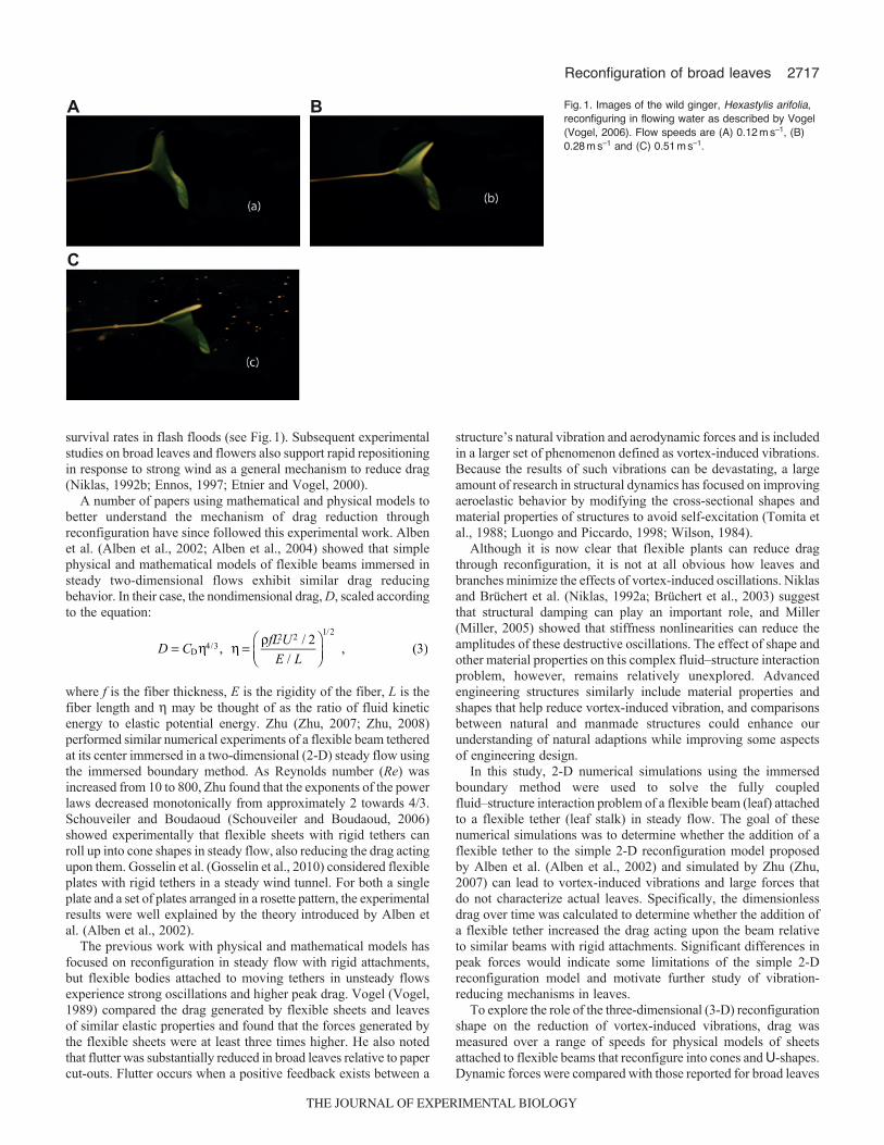
survival rates in flash floods (see Fig.1). Subsequent experimentalstudies on broad leaves and flowers also support rapid repositioningin response to strong wind as a general mechanism to reduce drag(Niklas, 1992b; Ennos, 1997; Etnier and Vogel, 2000).
A number of papers using mathematical and physical models tobetter understand the mechanism of drag reduction throughreconfiguration have since followed this experimental work. Albenet al. (Alben et al., 2002; Alben et al., 2004) showed that simplephysical and mathematical models of flexible beams immersed insteady two-dimensional flows exhibit similar drag reducingbehavior. In their case, the nondimensional drag, D, scaled accordingto the equation:
where f is the fiber thickness, E is the rigidity of the fiber, L is thefiber length and may be thought of as the ratio of fluid kineticenergy to elastic potential energy. Zhu (Zhu, 2007; Zhu, 2008)performed similar numerical experiments of a flexible beam tetheredat its center immersed in a two-dimensional (2-D) steady flow usingthe immersed boundary method. As Reynolds number (Re) wasincreased from 10 to 800, Zhu found that the exponents of the powerlaws decreased monotonically from approximately 2 towards 4/3.Schouveiler and Boudaoud (Schouveiler and Boudaoud, 2006)showed experimentally that flexible sheets with rigid tethers canroll up into cone shapes in steady flow, also reducing the drag actingupon them. Gosselin et al. (Gosselin et al., 2010) considered flexibleplates with rigid tethers in a steady wind tunnel. For both a singleplate and a set of plates arranged in a rosette pattern, the experimentalresults were well explained by the theory introduced by Alben etal. (Alben et al., 2002).
The previous work with physical and mathematical models hasfocused on reconfiguration in steady flow with rigid attachments,but flexible bodies attached to moving tethers in unsteady flowsexperience strong oscillations and higher peak drag. Vogel (Vogel,1989) compared the drag generated by flexible sheets and leavesof similar elastic properties and found that the forces generated bythe flexible sheets were at least three times higher. He also notedthat flutter was substantially reduced in broad leaves relative to papercut-outs. Flutter occurs when a positive feedback exists between a
= η η =ρ⎛
⎝⎜⎞⎠⎟
D CfL UE L
, / 2
/ , (3)D
4/32 2 1/2
structure’s natural vibration and aerodynamic forces and is includedin a larger set of phenomenon defined as vortex-induced vibrations.Because the results of such vibrations can be devastating, a largeamount of research in structural dynamics has focused on improvingaeroelastic behavior by modifying the cross-sectional shapes andmaterial properties of structures to avoid self-excitation (Tomita etal., 1988; Luongo and Piccardo, 1998; Wilson, 1984).
Although it is now clear that flexible plants can reduce dragthrough reconfiguration, it is not at all obvious how leaves andbranches minimize the effects of vortex-induced oscillations. Niklasand Brüchert et al. (Niklas, 1992a; Brüchert et al., 2003) suggestthat structural damping can play an important role, and Miller(Miller, 2005) showed that stiffness nonlinearities can reduce theamplitudes of these destructive oscillations. The effect of shape andother material properties on this complex fluid–structure interactionproblem, however, remains relatively unexplored. Advancedengineering structures similarly include material properties andshapes that help reduce vortex-induced vibration, and comparisonsbetween natural and manmade structures could enhance ourunderstanding of natural adaptions while improving some aspectsof engineering design.
In this study, 2-D numerical simulations using the immersedboundary method were used to solve the fully coupledfluid–structure interaction problem of a flexible beam (leaf) attachedto a flexible tether (leaf stalk) in steady flow. The goal of thesenumerical simulations was to determine whether the addition of aflexible tether to the simple 2-D reconfiguration model proposedby Alben et al. (Alben et al., 2002) and simulated by Zhu (Zhu,2007) can lead to vortex-induced vibrations and large forces thatdo not characterize actual leaves. Specifically, the dimensionlessdrag over time was calculated to determine whether the addition ofa flexible tether increased the drag acting upon the beam relativeto similar beams with rigid attachments. Significant differences inpeak forces would indicate some limitations of the simple 2-Dreconfiguration model and motivate further study of vibration-reducing mechanisms in leaves.
To explore the role of the three-dimensional (3-D) reconfigurationshape on the reduction of vortex-induced vibrations, drag wasmeasured over a range of speeds for physical models of sheetsattached to flexible beams that reconfigure into cones and U-shapes.Dynamic forces were compared with those reported for broad leaves
A B
C
Fig.1. Images of the wild ginger, Hexastylis arifolia,reconfiguring in flowing water as described by Vogel(Vogel, 2006). Flow speeds are (A) 0.12ms–1, (B)0.28ms–1 and (C) 0.51ms–1.
THE JOURNAL OF EXPERIMENTAL BIOLOGY
2718 The Journal of Experimental Biology 215 (15)
in air and water. The wakes generated behind the physical modelsand the leaves of the wild ginger Hexastylis arifolia and the wildviolet Viola papilionacea were quantified using 2-D planar particleimage velocimetry (PIV).
MATERIALS AND METHODSModel equations and dimensionless parameters
The full Navier–Stokes equations were used to describe the motionof the fluid. The 2-D equations can be rewritten in dimensionlessform as follows:
where u is the fluid velocity, p is the pressure, f is the force perunit area applied to the fluid by the immersed boundary, is thedensity of the fluid, is the dynamic viscosity of the fluid, t isdimensional time and x is the position in Cartesian coordinates. Notethat — denotes the gradiant. The dimensionless variables are u�, x�,p�, t� and f�, which represent the dimensionless velocity, position,pressure, time and force per unit area, respectively. L is acharacteristic length (such as the length of the leaf) and U is acharacteristic velocity (such as the maximum free stream velocity)used in the nondimensionalization. Re is then given by Eqn5 andrepresents the order of magnitude of the ratio of inertial and viscousforces in the fluid.
The dimensionless equation describing a one-dimensional elasticstructure in a fluid can be written as follows (Alben, 2008; Alben,2009):
where m� is the dimensionless mass, s� is the dimensionless arclength, T is the tension, k�bend is the dimensionless bending stiffness,F� is the dimensionless force per unit length acting on the structure,� is the curvature, n is the unit vector pointing normal to theboundary and s is the unit vector tangent to the boundary. Thedimensionless mass and bending stiffness of the boundary may thenbe written as:
where s is the mass per unit length of the boundary and EI is thedimensional flexural stiffness. The dimensionless bending stiffness,k�bend, may also be considered as the dimensionless flexural stiffness.
Numerical methodIn this paper, the 2-D immersed boundary method is used tosimulate a flexible fiber (equivalent to a sheet in the 3-D fluid)
∂ ′∂
+ ′ ∇′ ′ = −∇′ ′ + ∇′ ′ + ′
∇′ ′ =t
pRe
uu u u f
u
1
0 . (4)
2
=μ
ρRe
LU . (5)
′ = ′ =
′ =ρ
′ =
′ =ρ
∇′ = ∇
Ut
tUL
ppU L
UL
L
uu
xx
ff
, (6)2
2
′∂
∂ ′′ ′ =
∂∂ ′
−∂
∂ ′κ + ′′m
ts t
sTs k
snX F( , ) ( ˆ) ( ˆ) , (7)
2
2 bend
2
2
=ρ
′kEI
U L , (8)bend 2 3
′ =ρρ
mL
, (9)s
attached to a flexible beam immersed in a viscous, incompressiblefluid (Fig.2). The immersed boundary method has been usedsuccessfully to model a variety of problems in fluid dynamicswhere the interactions between an incompressible viscous fluidand a deformable elastic boundary are significant. Some examplesof biological problems that have been studied with the immersedboundary method include lamprey swimming (Tytell et al., 2010),jellyfish feeding (Hamlet et al., 2011), flow-through heart valves(Griffith et al., 2009) and ciliary-driven flows (Grünbaum et al.,1998).
In the immersed boundary framework, the Navier–Stokesequations (Eqn4) are solved on a fixed Cartesian grid. The elasticityequation for the boundary (Eqn7) is solved on a moving Lagrangiangrid. The fluid equations are coupled to the boundary equationsthrough the following fluid–structure interaction equations:
where F�(s�,t�) is the dimensionless force per unit length acting onthe fluid, X�(s�,t�) gives the dimensionless Cartesian coordinates ofthe boundary and U�(s�,t�) is the dimensionless local fluid velocityat the boundary point s�. Eqn10 communicates the force exerted bythe boundary on the fluid grid using a smoothed 2-D Dirac deltafunction (x�). Once the Navier–Stokes equations have updated thefluid information for the time step, Eqn11 is used to interpolate thelocal fluid velocity at each boundary point and move the boundaryat the estimated velocity. This enforces the no-slip conditionassociated for a viscous fluid.
The exact numerical algorithm used in this paper is described indetail in Peskin and McQueen (Peskin and McQueen, 1996) withthe exception of the discretization of the -function. The choice of-function used here is detailed in Peskin and Printz (Peskin andPrintz, 1993) and is given by the following equations:
∫( ) ( ) ( )′ ′ ′ = ′ ′ ′ ′ ′ δ ′ − ′ ′ ′ ′t s t t s t sf x F X x X, ( , ), ( , ) d , (10)
∫( ) ( ) ( )∂ ′ ′ ′∂ ′
= ′ ′ ′ ′ = ′ ′ ′ δ ′ − ′ ′ ′ ′s tt
s t t s tX
U X u x x X x( , )
( , ) , ( , ) d , (11)
U
Lleafstalk=L
20L
20L
30h
5L
Lleaf=L
0.1L
Fig.2. Numerical setup of the immersed boundary simulations. Flow isdriven past a flexible leaf modeled here in one dimension as a beam (thetwo-dimensional interpretation in three-dimensional flow is a sheet) with alength set to Lleaf. The leaf is then attached to a flexible leafstalk of lengthLleafstalk modeled as a beam that is fixed at its base. The attachment of theleaf to the leafstalk is made using a pair of springs that resists deflectionsfrom 90deg of the leaf relative to the leafstalk. h, height.
THE JOURNAL OF EXPERIMENTAL BIOLOGY
2719Reconfiguration of broad leaves
where x� is the spatial step size in both the x�- and y�-directions,and x� denotes the discretized version of the -function.
Numerical setupIn the following simulations, a computational channel was used withdimensions 20L�20L. To avoid the placement of target pointsdirectly on the boundary and reflection of forces across the periodicdomain, this channel was placed within a slightly larger periodicdomain, of size (20L+30h)�(20L+30h), where hx�y� is themesh width of the fluid grid and L0.0333h. The two edges of thecomputational channel oriented parallel to the flow were made ofimmersed boundary points that were linked by stiff linear springsto stationary target points with dimensionless stiffness k�targ10. TheNavier–Stokes equations were solved on a 630�630 Cartesian grid,and the fiber and beam attachments were each discretized on aLagrangian array of 60 points.
Parabolic flow with maximum velocity U�max was driven withinthe channel and upstream of the model leaf by applying an externalforce, f�ext, to the fluid proportional to the difference between thedesired fluid velocity and the actual fluid velocity. Parabolic flowwas applied because this is the steady-state profile for flowthrough a channel at this Re. This force was applied to a strip ofwidth L/6 upstream of the base of the attachment using thefollowing equations:
Note that the maximum velocity occurs in the middle of the channel,and the indices of j are equal to –1, –2, etc. for regions of the domainbelow the immersed floor. The difference between the actual anddesired velocities was controlled with a ‘stiffness’ parameter,k�ext10, such that the difference between the two velocities wasalways less than 0.1%.
δ = ′ φ′
Δ ′⎛⎝⎜
⎞⎠⎟
φ′′
⎛⎝⎜
⎞⎠⎟′
−xxx
yx
∆∆
, (12)∆x2
( )φ =+
π⎛⎝⎜
⎞⎠⎟
⎛
⎝⎜⎞
⎠⎟≤
⎧
⎨⎪⎪
⎩⎪⎪
rr
r14
1 cos2
, | | 2
0,otherwise
, (13)
( )( ) ( )=
− ′ −
≤ ≤ ≤ ≤
⎧
⎨⎪⎪
⎩⎪⎪
′
′u ui j
k i j i j
jh L if ( , ), , ,
0 20 ,10 15
0,otherwise
, (14)ext
ext targ
( ) = −−⎛
⎝⎜⎞⎠⎟
⎛
⎝⎜⎜
⎞
⎠⎟⎟
⎡
⎣
⎢⎢⎢⎢
⎤
⎦
⎥⎥⎥⎥
′′
u i jU
jhL,
10.5
10
0
. (15)targmax
2
Dimensionless lift and drag were calculated as functions of timeby summing the forces at each immersed boundary point at eachtime step and taking the opposite sign of that value. In this paper,the dimensionless lift force, F�L, is defined as the force actingperpendicular to the direction of flow, and the dimensionless drag,F�D, is defined as the force acting parallel to the direction of flow.
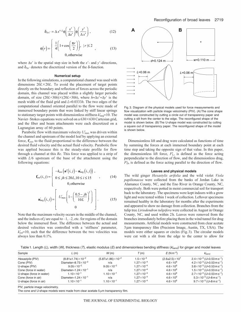
Leaves and physical modelsThe wild ginger Hexastylis arifolia and the wild violet Violapapilionacea were collected from the banks of Jordan Lake inAlamance County, NC, and the Eno River in Orange County, NC,respectively. Both were potted in moist commercial soil for transportback to the laboratory. The specimens were kept indoors with a growlight and were tested within 1week of collection. Leftover specimensremained healthy in the laboratory for months after the experimentsand appeared to show no damage from collection. Branches from thetulip tree Liriodendron tulipifera were collected in August in OrangeCounty, NC, and used within 2h. Leaves were removed from thebranches immediately before placing them in the wind tunnel for dragmeasurements. Artificial models were constructed from clear acetate5m transparency film (Precision Image, Austin, TX, USA). Themodels were either squares or circles (Fig.3). The circular modelswere cut with a slit from the edge to the center to allow for
A B
d=0.124 m w=0.110 m
L=0.06 m L=0.06 m
Fig.3. Diagram of the physical models used for force measurements andflow visualization with particle image velocimetry (PIV). (A)The cone shapemodel was constructed by cutting a circle out of transparency paper andcutting a slit from the center to the edge. The reconfigured shape of themodel is shown below. (B)The U-shape model was constructed by cuttinga square out of transparency paper. The reconfigured shape of the modelis shown below.
Table1. Length (L), width (W), thickness (T), elastic modulus (E) and dimensionless bending stiffness (k�bend) for ginger and model leaves
PIV, particle image velocimetry.The cone and U-shape models were made from clear acetate 5m transparency film.
THE JOURNAL OF EXPERIMENTAL BIOLOGY
2720 The Journal of Experimental Biology 215 (15)
reconfiguration into a cone under flow. All models were attached attheir centers to either a rigid rod or a flexible plastic beam. Thisallowed the square models to reconfigure into a U-shape and thecircular models to reconfigure into cones. The dimensional anddimensionless lengths and bending stiffnesses of the leaves, modelsand attachments are summarized in Tables1 and 2.
Flow tank and wind tunnelFor aquatic measurements, drag measurements and flowmeasurements using PIV were performed on single leaves andmodels clamped at the proximal ends of their leafstalks (or beamattachments) in a drafting fork as described by Vogel (Vogel, 2006).The flow tank contained a 0.350�0.325m working cross-sectionand was similar to that described by Vogel and LaBarbera (Vogeland LaBarbera, 1978). Drag measurements were taken using flow-straightening collimators placed upstream and downstream of theworking section. For the PIV measurements, the collimators wereremoved in a manner similar to that used in Vogel’s experimentson Hexastylis (Vogel, 2006). Average flow velocities were measuredusing a Vernier Software & Technology flow rate sensor (FLO-BTA, Beaverton, OR, USA). The flow velocity used for PIV wasset to 0.53ms–1 unless otherwise noted. The flow velocities for theforce measurements were varied from 0.3 to 1ms–1.
For aerial force measurements, the models were mounted in theworking section of an open circuit wind tunnel (Tucker and Parrott,1970). Wind velocities were measured using a Fisher ScientificTraceable Digital Anemometer (Hampton, NH, USA). Wind speedswere increased in 0.5ms–1 increments and were varied from 3 to11ms–1. Models were attached to the base of an aluminum beamusing a flexible beam of 6cm length (see details below).
Particle image velocimetryFlow velocity measurements were made using 2-D planarinstantaneous and time-averaged PIV. The laser sheet for the PIVmeasurements was generated from a 50mJ double-pulsed Nd:YAG
laser (Continuum, Santa Clara, CA, USA), which emitted light ata wavelength of 532nm with a maximum repetition rate of 15Hz.The laser beam was converted into a planar sheet approximately3mm thick using a set of focusing optics. The laser sheet was locatedin the x–y plane upstream of the working section. A mirror wasused to reflect the laser sheet down onto the leaf (Fig.4). The time
Table2. Dimensions of ginger leafstalks and model attachment beams
L, length of beam; R, radius of specimens; E, Youngʼs modulus; k�bend, dimensionless bending stiffness.
LaserMirror
Laser sheet
LeafFlow
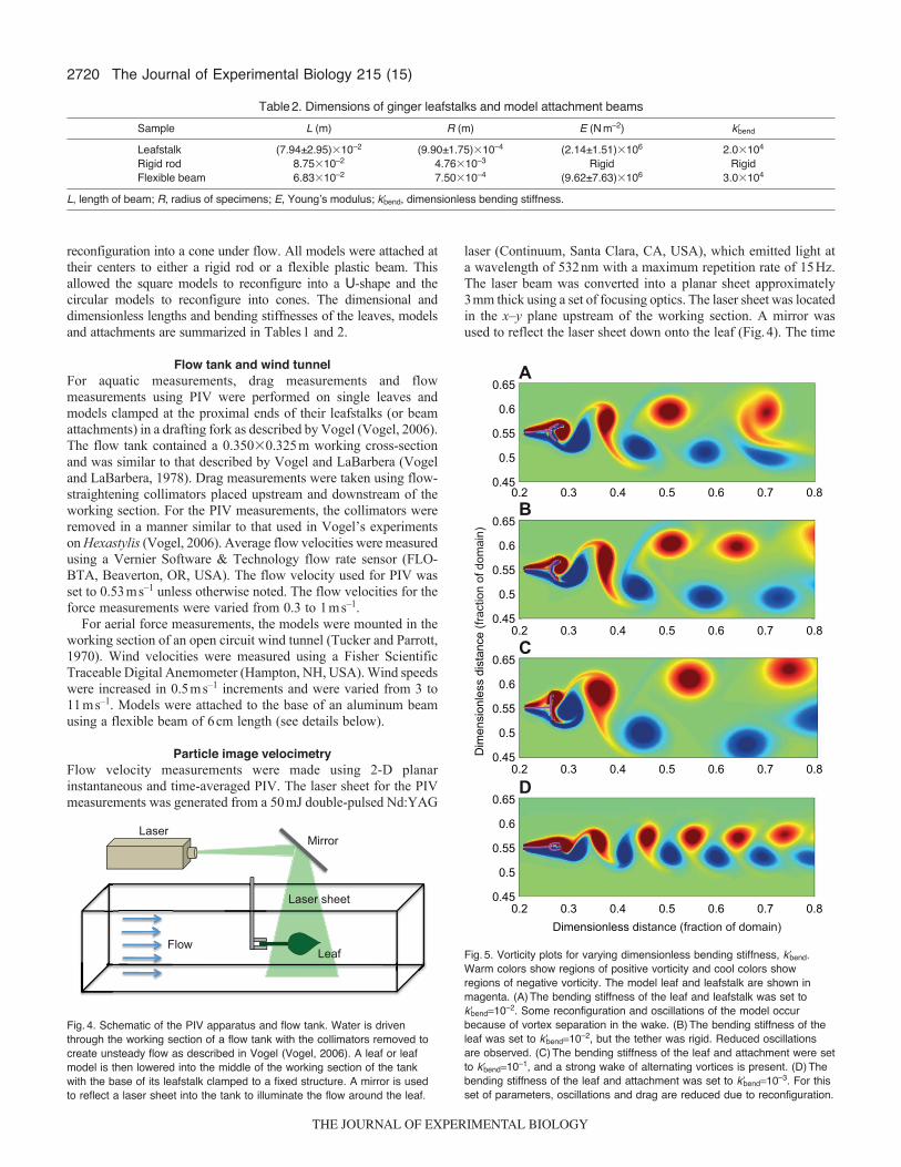
Fig.4. Schematic of the PIV apparatus and flow tank. Water is driventhrough the working section of a flow tank with the collimators removed tocreate unsteady flow as described in Vogel (Vogel, 2006). A leaf or leafmodel is then lowered into the middle of the working section of the tankwith the base of its leafstalk clamped to a fixed structure. A mirror is usedto reflect a laser sheet into the tank to illuminate the flow around the leaf.
A0.65
0.6
0.55
0.5
0.450.2 0.3 0.4 0.5 0.6 0.7 0.8B
0.65
0.6
0.55
0.5
0.450.2 0.3 0.4 0.5 0.6 0.7 0.8C
0.65
0.6
0.55
0.5
0.450.2 0.3 0.4 0.5 0.6 0.7 0.8
D0.65
0.6
0.55
0.5
0.450.2 0.3 0.4 0.5 0.6 0.7 0.8
Dimensionless distance (fraction of domain)
Dim
ensi
onle
ss d
ista
nce
(frac
tion
of d
omai
n)
Fig.5. Vorticity plots for varying dimensionless bending stiffness, k�bend.Warm colors show regions of positive vorticity and cool colors showregions of negative vorticity. The model leaf and leafstalk are shown inmagenta. (A)The bending stiffness of the leaf and leafstalk was set tok�bend10–2. Some reconfiguration and oscillations of the model occurbecause of vortex separation in the wake. (B)The bending stiffness of theleaf was set to k�bend10–2, but the tether was rigid. Reduced oscillationsare observed. (C)The bending stiffness of the leaf and attachment were setto k�bend10–1, and a strong wake of alternating vortices is present. (D)Thebending stiffness of the leaf and attachment was set to k�bend10–3. For thisset of parameters, oscillations and drag are reduced due to reconfiguration.
THE JOURNAL OF EXPERIMENTAL BIOLOGY
2721Reconfiguration of broad leaves
interval of separation between two image pairs was varied from125–150s. A 14bit CCD camera (Imager Intense, LaVision,Ypsilanti, MI, USA) with a 1376�1040pixel array was used tocapture images. The spatial resolution was approximately0.05mmpixel–1. Uniform seeding was accomplished using 10mhollow glass spheres that were inserted in the flow tank and mixedto achieve a near-homogeneous distribution prior to each experiment.Volume fractions were such that approximately 40–50 particles werevisible within each 64�64pixel window. In typical experimentsthere was a maximum particle displacement of 0.8mm (or 14pixels)within the correlation window, which corresponds to 25%displacement in a 64�64pixel window.
For the actual leaves, the PIV analysis was performed beyondthe point where the leaf surface was reconfigured and remained staticduring the entire time of acquisition. Hence, no masking of the leafsurface was performed. The physical models were transparent sothat the masking of these surfaces was not necessary. Image pairswere analyzed using a single pass cross-correlation algorithm inDavis 7.0 (LaVision) using interrogation windows of size64�64pixels with 50% overlap. No pre-processing of the raw datawas performed prior to this step. For each PIV set of time averageddata, 204 images were recorded for processing, resulting in a totalof 102 velocity vector fields from which to generate mean flowfield and statistics. No smoothing algorithms or other post-processing techniques were employed on the data.
Drag measurementsDrag was measured using a method similar to that described in Vogel(Vogel, 1989). Strain gauges (120ohm) were affixed to oppositesides of an aluminum beam. The beam was arranged as a cantileverbeam that was 1.27mm thick, 14mm wide and 135mm long. Thenatural frequency of the beam was approximately 54Hz in air and30Hz in water. The strain gauges made up two arms of an ordinaryDC Wheatstone bridge. The imbalance of the bridge fed into acomputer through a National Instruments DAQ (cDAQ-9172,Austin, TX, USA) and recorded at a sampling rate of 1000Hz usingMATLAB software (The MathWorks, Natick, MA, USA). Thesignal was then processed in MATLAB using a Butterworth low-pass filter (120Hz cutoff frequency) and 60Hz band-stop filter. Thecantilever beam was gravimetrically calibrated while clampedhorizontally by hanging weights from the attachment site.
RESULTS AND DISCUSSIONNumerical simulations
To examine the effect of varying stiffness on reconfigurationshapes and forces generated by model leaves attached to flexiblebeams in steady flow, numerical simulations were performed atRe235 for k�bend2�10–1, 2�10–2, 10–2 and 10–3. Vorticitysnapshots taken at t�120 are shown in Fig.5. Warm colors representregions of positive vorticity and cool colors show regions ofnegative vorticity. The model leaf and leafstalk are shown inmagenta. When the leaf and leafstalk were set to k�bend10–2, theleaf reconfigured into a U-shape and some oscillations occurredbecause of vortex separation in the wake of the model (Fig.5A, seesupplementary material Movie1). When the bending stiffness of theleaf was kept at k�bend10–2 and the tether was made rigid, the leafagain reconfigured into a U-shape but reduced oscillations wereobserved (Fig.5B, see supplementary material Movie2). Thebending stiffness of the leaf and attachment were then made stifferand set to k�bend2�10–1 and a strong wake of alternating vorticeswas present (Fig.5C, see supplementary material Movie3). Finally,the bending stiffness of the leaf and attachment were made ratherflexible with k�bend10–3. For this set of parameters, oscillations anddrag were reduced because of substantial reconfiguration andreduced frontal area of the leaf (Fig.5D).
Dimensionless drag and lift are shown as functions ofdimensionless time, t�, in Fig.6. In general, average forces decreaseas the bending stiffness decreases. The initial increase in the drag(0<t�<5) was due to the acceleration of the fluid. For k�bend2�10–1,2�10–2 and 10–2 there was an initial decrease in drag (5<t�<20)followed by an increase in both the magnitude and amplitude ofoscillations (t�>20). An inspection of the corresponding movie (seesupplementary material Movies1–3) showed that this increasecorresponded to the onset of large vortex. The amplitude of theoscillations of the lift forces also increased as the system settledinto a state of large vortex separation coupled to the oscillation ofthe leaf for t�>20. Taking into account both components of the force,the total peak forces on the leaf are 1.5 to three times higher afterthe onset of large vortex-induced oscillations.
Fig.7 shows the average dimensionless forces calculated beforethe onset of vortex shedding (10<t�<20) and after the onset of vortexshedding (t�>40). The average magnitude of the dimensionless forcewas calculated as F�√FD�
2+FD�2. For the purpose of quantifying the
k�bend=2�10–1
k�bend=2�10–2
k�bend=10–2
k�bend=10–3
A B4.5
43.5
32.5
21.5
10.5
0
Dim
ensi
onle
ss d
rag
(F� D)
Dim
ensi
onle
ss li
ft (F
� L)
Dimensionless time
0 20 40 60 80 100 120
1.5
1
0.5
0
–0.5
–1
–1.50 20 40 60 80 100 120
Fig.6. Dimensionless drag and lift as functions of dimensionless time, t�. In these numerical simulations, flow is driven past a flexible leaf attached to aflexible leafstalk at Re235 for dimensionless bending stiffnesses set to k�bend2�10–1, 2�10–2, 10–2 and 10–3. In general, average forces decrease as thebending stiffness decreases. (A)The initial increase in the drag (0<t�<5) is due to the acceleration of the fluid. There is an initial decrease (5<t�<20) followedby an increase in both the magnitude and degree of oscillations (t�>20). An inspection of the movies (see supplementary material Movies1–3) shows thatthis increase corresponds to the onset of large vortex separation coupled to the oscillations of the leaf. (B)The magnitude of the lift forces perpendicular tothe direction of flow also increase as the system settles into a state of large vortex separation coupled to the oscillation of the leaf for t�>20.
THE JOURNAL OF EXPERIMENTAL BIOLOGY
2722
variations in peaks, the vertical bars on the graph show the standarddeviation in the force measurements. This analysis was performed toquantify the effect of vortex-induced vibrations on the fluid dynamicforces acting on the models. Average forces taken before vortexshedding are comparable to those reported by Zhu (Zhu, 2007; Zhu,2008). The average force generated during vortex shedding is morethan twice as much as that generated before vortex shedding for thestiffest model (k�bend2�10–1). This difference decreases as theflexibility increases.
To consider the effect of increased velocity and frequency ofvortex shedding, numerical simulations were performed for U�maxg,1, 2 and 4 and with k�bend10–2. Here k�bend is determined bynormalizing the bending stiffness with respect to a fixed U1.Vorticity snapshots taken at t�120 are shown in Fig.8. Warm colorsrepresent regions of positive vorticity and cool colors show regionsof negative vorticity. The amount of reconfiguration increased asthe velocity increased (see supplementary material Movies4, 5). Thewidth of the vortex wake decreased as the velocity increased, whichcorrelates to the reduction in dimensionless drag. Fig.8D andsupplementary material Movie5 show an interesting result that isdue to numerical effects. At t�≈80, the tips of the leaf adhered toeach other, effectively locking the model into a streamlined shape.As a result, both oscillations and drag are reduced for t�>80. Thisnumerical error was due to under-resolving the flow near two endsof the immersed boundary, but it does illustrate how a body stuckin a streamlined position potentially experiences lower drag.
Dimensionless lift and drag are plotted as functions ofdimensionless time for the above four velocities with k�bend10–2 inFig.9. For free-stream velocities set to Umaxg, 1 and 2, themagnitudes of the dimensionless lift and drag decreased as thevelocity increased because of the reconfiguration of the model leaf.Force coefficients then increased as the velocity increased to 4because the interaction of the fluid and structure created largeroscillations of the leaf. Around t�80, the tips of the model leafadhered as a result of numerical error, and the dimensionless dragand amplitude of the oscillations decreased.
The Journal of Experimental Biology 215 (15)
Physical modelsWhen the flexible square cut-out is attached to a rigid rod, the sheetreconfigures into a stable U-shape. The wake consists of twooppositely spinning vortices (Fig.10A). This was similar to whatwas reported for 2-D flows experimentally by Alben et al. (Albenet al., 2004) and through simulations in two dimensions by Zhu(Zhu, 2008) and in three dimensions by Zhu et al. (Zhu et al., 2011).The basic idea is that the low pressure region in the recirculationzone leads to reconfiguration of the beam (shape self-similarity)and a transition from the classical U2 drag scaling of rigid bodiesat high Re to a new U4/3 drag law.
When the flexible square was attached to a flexible beam andimmersed in a turbulent flow, significant oscillations occurred,and the sheet did not long retain the reconfigured U-shape. Thetime-averaged spatial distribution of velocity behind the sheet isshown in Fig.10B. Notice that the recirculation zone was not as
10–3 10–2 10–1 100 0.5
1
1.5
2
2.5
3
3.5
4
Dimensionless bending stiffness (k�bend)
Dim
ensi
onle
ss fo
rce
(F�)
Before sheddingDuring shedding
Fig.7. Average force coefficients versus the dimensionless bendingcoefficient, k�bend, calculated before the onset of vortex shedding for10<t�<20 and after the onset of vortex shedding for t�>40. For the purposeof quantifying the variations in peaks, the vertical bars show the standarddeviations in the force measurements. Note that the average force actingon the model leaf during vortex shedding is more than twice as much asthat before vortex shedding for the stiffest model. The average forcemeasured during shedding approaches the force measured beforeshedding for the most flexible models.
A0.65
0.6
0.55
0.5
0.450.2 0.3 0.4 0.5 0.6 0.7 0.8B
0.65
0.6
0.55
0.5
0.450.2 0.3 0.4 0.5 0.6 0.7 0.8
C0.65
0.6
0.55
0.5
0.450.2 0.3 0.4 0.5 0.6 0.7 0.8
D0.65
0.6
0.55
0.5
0.450.2 0.3 0.4 0.5 0.6 0.7 0.8
Dimensionless distance (fraction of domain)
Dim
ensi
onle
ss d
ista
nce
(frac
tion
of d
omai
n)
Fig.8. Vorticity plots for increasing free-stream velocities set to U�max1⁄2, 1,2 and 4 (top to bottom) with k�bend10–2. Warm colors show regions ofpositive vorticity and cool colors show regions of negative vorticity. Theamount of reconfiguration increases as the velocity increases. The width ofthe vortex wake decreases as the velocity increases, which is partiallyresponsible for the reduction in drag. In the last image, the tips of themodel leaf have adhered together because of effects, stabilizing the leaf(see supplementary material Movie5).
THE JOURNAL OF EXPERIMENTAL BIOLOGY
2723Reconfiguration of broad leaves
well formed as that shown for the case with the rigid attachment.The instantaneous distributions of velocity (Fig.10C,D) showedperiodic separation of regions of vorticity behind the sheet. Thevortex shedding also induced forces acting perpendicular to thedirection of flow. These observations were consistent with thebehavior of aerial broad leaves when compared with flexiblemodels attached to flexible beams, as described by Vogel (Vogel,1989).
Wakes of herbaceous leaves and conesTo examine how actual broad leaves differ from the 2-D numericalsimulations and physical models, PIV was used to resolve thewakes behind the leaves. As described by Vogel (Vogel, 2006),fully submerged H. arifolia and V. papilionacea leavesreconfigured into stable cones, even in the presence of highlyturbulent flows. The cones became tighter as the flow speed wasincreased. Instantaneous snapshots of V. papilionacea leaves are
U�max=½U�max=1U�max=2U�max=4
A B3.5
3
2.5
2
1.5
1
0.5
0
Dim
ensi
onle
ss d
rag
(F� D)
Dim
ensi
onle
ss li
ft (F
� L)
Dimensionless time
0 20 40 60 80 100 120
0.6
0.4
0.2
0
–0.2
–0.4
–0.6
–0.80 20 40 60 80 100 120
Fig.9. Dimensionless lift and drag as functions of dimensionless time for four dimensionless velocities with k�bend10–2. For free-stream velocities set toU�max1⁄2, 1, 2 and 4, the magnitudes of the dimensionless lift and drag decrease as the velocity increases because of the reconfiguration of the model leaf.Force coefficients then increase as the velocity increases to 4 as the interaction of the fluid and structure creates larger oscillations. Around t�80, the tips ofthe model leaf adhere because of numerical effects, and the force coefficients as well as the oscillations decrease (see supplementary material Movie5).
A
C D
B60
40
20
0
–20
–40
–60
40
20
0
–20
–40
40
30
20
10
0
–10
–20
–30
–40
–50
40
30
20
10
0
–10
–20
–30
–40
–500 20 40 60 80 100
x (mm)0 20 40 60 80 100
x (mm)
0 40 80 120x (mm)
0 40 80 120 160x (mm)
y (m
m)
y (m
m)
y (m
m)
y (m
m)
Fig.10. Time-averaged velocity vectorsobtained using PIV showing the wakesof a flexible sheet attached to a rigidbeam (A) and a flexible sheet attachedto a flexible beam (B) at Re80,000.The insets show the laser plane as agreen dotted line. Note that the laserplane would be coming towards thereader in the third dimension. The whitedotted line in A shows the edges of thetransparency that has reconfigured intoa U-shape. Two stable oppositelyspinning vortices are observed in A,which agrees with the results of Albenet al. (Alben et al., 2002). No structuredwake is apparent in B. Instantaneoussnapshots of the velocity fields in thewake of a flexible sheet attached to aflexible beam are shown in C and D.Strong shedding of vorticity and largeoscillations are observed.
THE JOURNAL OF EXPERIMENTAL BIOLOGY
2724
compared with the flexible sheet models in Fig.11. Largeoscillations and high-frequency deformations of the flexible sheetswere observed. Some motion of the V. papilionacea leaves wasobserved because of the strong unsteadiness of the flow, but theleaf retained its reconfigured shape throughout the experiment.Similar results were also observed for H. arifolia.
The time-averaged spatial distribution of velocity in the wake ofH. arifolia is shown in Fig.12A. A stable recirculation zone wasformed in the wake of the reconfigured leaf, creating a low-pressurezone that aids in ‘coning.’ Significant shedding of vorticity was notobserved for the ginger leaf, which reduced any hydrodynamic forcesacting perpendicular to the flow. Similar behavior was also observedfor the V. papilionacea leaves. These results were compared withtime-averaged spatial distributions of the velocity in the wakes ofsheets designed to reconfigure into cone shapes attached to flexiblebeams (Fig.12B). A similar wake structure was observed. The
The Journal of Experimental Biology 215 (15)
reconfiguration shape was also stable, although it appeared that theactual leaves were more stable.
Forces on flexible sheets and conesTo confirm that drag was reduced for flexible sheets that reconfigureinto cones rather than U-shapes, forces on the transparency modelswere measured in the flow tank. The plan form (or projected, planar)area of both models was approximately 0.012m2 (see Tables1 and2 for details). No adjustment was made in the dimensionless forcecalculations to account for the reconfiguration of the leaves andmodels. The purpose of the physical models in this case was not somuch to mimic the leaves but rather to compare these tworeconfiguration shapes in general. The H. arifolia leaves, V.papilionacea leaves and physical models made out of transparencypaper were almost neutrally buoyant, such that the effects of theiradditional masses relative to the fluid dynamic forces were
t=0 t=0.79 s t=1.15 s
t=1.51 s t=3.65 s t=4.51 s
40
30
20
10
0
–10
–20
–30
–40
–50
y (m
m)
x (mm)0 20 40 60
A
B 20
10
0
–10
–20
–30
y (m
m)
x (mm)0 20 40
Fig.11. Times series of images of a flexible sheet attachedto a flexible wire (A) and a Viola papilionacea leaf (B) atRe80,000. The flexible sheet reconfigures into a U-shape,but significant high-frequency distortions of the sheet areobserved. Because of the turbulent nature of the fluid, the V.papilionacea leaf reconfigures into a cone shape with somemovement.
THE JOURNAL OF EXPERIMENTAL BIOLOGY
2725Reconfiguration of broad leaves
negligible. Fig.13A shows the dimensionless drag averaged over30s versus free-stream velocity ranging from 0.3 to 1ms–1. Theerror bars show the standard deviations. For comparison, values forHexastylis reported by Vogel (Vogel, 2006) are also plotted. Ingeneral, dimensionless drag decreases with velocity. Drag is lowestfor H. arifolia, and the U-shape model generates the largest drag.Fig.13B shows the peak dimensionless drag averaged over 1sintervals for a total of 30s. The error bars show the standarddeviations. Peaks were taken over 1s intervals because the dominantfrequencies were on the order of 1–5Hz. However, peaks taken overintervals of varying lengths show similar results. Peak drag is higherfor the U-shape model than for the cone model and leaves for allvelocities considered.
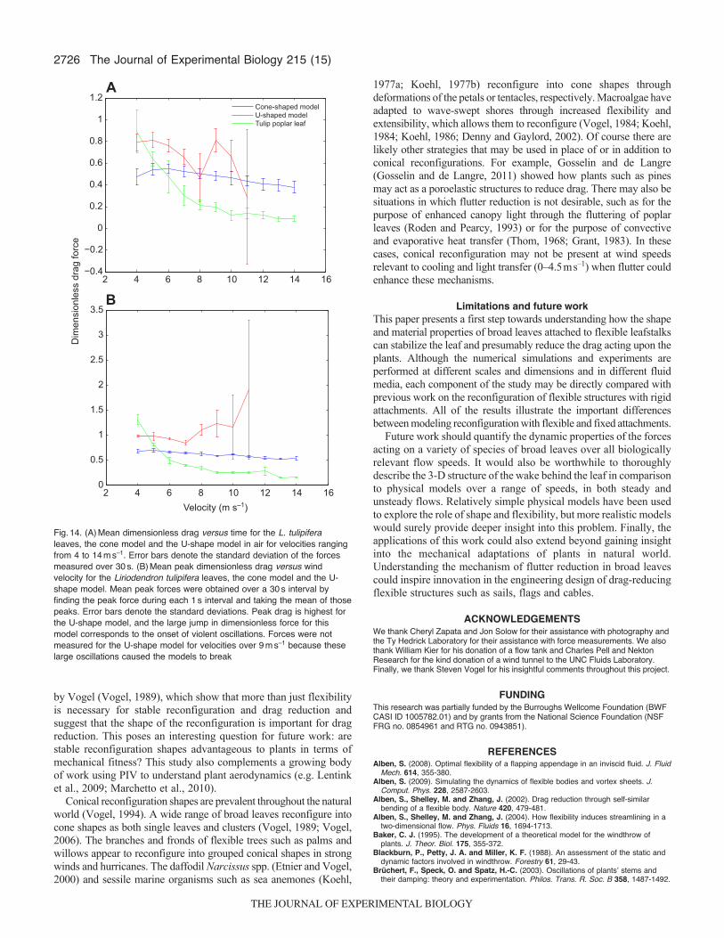
To consider the effects of the inertia of the leaves and modelsfor the aerial case, both cone and U-shape transparency models wereplaced in a wind tunnel. Forces were also measured for L. tulipiferaleaves for comparison. Mean dimensionless drag versus time forthe two models and the L. tulipifera leaves for velocities rangingfrom 4 to 14ms–1 are shown in Fig.14B. The error bars indicatethe standard deviations. For velocities of 5ms–1 and greater, meandrag is generally lowest for the actual leaves and highest for the U-shape model. Large oscillations were observed for the U-shapemodel at velocities of 9ms–1 and greater, corresponding to the largestandard deviations in drag. Fig.14 shows the mean peak drag takenover 1s intervals for the two physical models and the L. tulipiferaleaves. The error bars show the standard deviations. The large peakdimensionless drag generated by the U-shape model is apparent forwind speeds greater than 9ms–1. Oscillations for the cone modeland leaves were relatively small at these wind speeds, as indicatedby the small standard deviations (see supplementary materialMovies6, 7). Forces were not measured for the U-shape model forvelocities over 11ms–1 as violent oscillations caused the models tobreak.
ConclusionsThe main result from the numerical simulation is that the additionof a flexible tether to the simple 2-D flexible beam model of a leafresults in larger oscillations, stronger vortex shedding and increaseddrag when compared with equivalent 2-D models with fixedattachments. The PIV results indicate that herbaceous broad leavesreconfigure into cones, and the wake behind the leaves contains arelatively stable pair of alternately spinning vortices. Physical modelsthat reconfigure into cones exhibit similar behavior. Sheets thatreconfigure into U-shapes (the 3-D analog of the simple 2-D beammodel) exhibit strong oscillations and vortex shedding. Force
measurements on the physical models indicate that the largeoscillations present in the U-shape models correspond to large peakdrag forces. This effect is magnified in air when inertial effects ofthe models are non-negligible. These results confirm those reported
A40
30
20
10
0
–10
–20
–30
–40
–500 20 40 60 80 100
x (mm)
y (m
m)
B80
60
40
20
0
–20
–40
–60
–80
0 50 100 150 200x (mm)
y (m
m)
Fig.12. Time-averaged velocity vectorsobtained using PIV showing the stablerecirculation zone in the wakes of an H.arifolia leaf (A) and a flexible sheetattached to a flexible beam that hasreconfigured into a cone (B) at Re80,000.The insets show the laser plane as agreen dotted line. Note that the laser planewould be coming towards the reader in thethird dimension. A pair of oppositelyspinning vortices is apparent in the wakeof the transparent sheet.
0.2 0.4 0.6 0.8 1 1.20
0.2
0.4
0.6
0.8
1
1.2
1.4
Dim
ensi
onle
ss d
rag
forc
eCone-shaped modelU-shaped modelVogel Hexastylis
0.2 0.4 0.6 0.8 1 1.20
0.2
0.4
0.6
0.8
1
1.2
1.4
Velocity (m s–1)
Cone-shaped modelU-shaped model
A
B
Fig.13. (A)Mean dimensionless drag versus time for the cone and U-shapemodels with plan form areas of 0.012m2 in water for velocities ranging from0.3 to 1ms–1. The green line denotes the drag measurements forHexastylis leaves reported by Vogel (Vogel, 2006). Error bars denote thestandard deviation of the forces measured over 30s. (B)Mean peakdimensionless drag versus velocity for the cone and U-shape models.Mean peak forces were obtained over a 30s interval by finding the peakforce during each 1s interval and taking the mean of those peaks.
THE JOURNAL OF EXPERIMENTAL BIOLOGY
2726
by Vogel (Vogel, 1989), which show that more than just flexibilityis necessary for stable reconfiguration and drag reduction andsuggest that the shape of the reconfiguration is important for dragreduction. This poses an interesting question for future work: arestable reconfiguration shapes advantageous to plants in terms ofmechanical fitness? This study also complements a growing bodyof work using PIV to understand plant aerodynamics (e.g. Lentinket al., 2009; Marchetto et al., 2010).
Conical reconfiguration shapes are prevalent throughout the naturalworld (Vogel, 1994). A wide range of broad leaves reconfigure intocone shapes as both single leaves and clusters (Vogel, 1989; Vogel,2006). The branches and fronds of flexible trees such as palms andwillows appear to reconfigure into grouped conical shapes in strongwinds and hurricanes. The daffodil Narcissus spp. (Etnier and Vogel,2000) and sessile marine organisms such as sea anemones (Koehl,
The Journal of Experimental Biology 215 (15)
1977a; Koehl, 1977b) reconfigure into cone shapes throughdeformations of the petals or tentacles, respectively. Macroalgae haveadapted to wave-swept shores through increased flexibility andextensibility, which allows them to reconfigure (Vogel, 1984; Koehl,1984; Koehl, 1986; Denny and Gaylord, 2002). Of course there arelikely other strategies that may be used in place of or in addition toconical reconfigurations. For example, Gosselin and de Langre(Gosselin and de Langre, 2011) showed how plants such as pinesmay act as a poroelastic structures to reduce drag. There may also besituations in which flutter reduction is not desirable, such as for thepurpose of enhanced canopy light through the fluttering of poplarleaves (Roden and Pearcy, 1993) or for the purpose of convectiveand evaporative heat transfer (Thom, 1968; Grant, 1983). In thesecases, conical reconfiguration may not be present at wind speedsrelevant to cooling and light transfer (0–4.5ms–1) when flutter couldenhance these mechanisms.
Limitations and future workThis paper presents a first step towards understanding how the shapeand material properties of broad leaves attached to flexible leafstalkscan stabilize the leaf and presumably reduce the drag acting upon theplants. Although the numerical simulations and experiments areperformed at different scales and dimensions and in different fluidmedia, each component of the study may be directly compared withprevious work on the reconfiguration of flexible structures with rigidattachments. All of the results illustrate the important differencesbetween modeling reconfiguration with flexible and fixed attachments.
Future work should quantify the dynamic properties of the forcesacting on a variety of species of broad leaves over all biologicallyrelevant flow speeds. It would also be worthwhile to thoroughlydescribe the 3-D structure of the wake behind the leaf in comparisonto physical models over a range of speeds, in both steady andunsteady flows. Relatively simple physical models have been usedto explore the role of shape and flexibility, but more realistic modelswould surely provide deeper insight into this problem. Finally, theapplications of this work could also extend beyond gaining insightinto the mechanical adaptations of plants in natural world.Understanding the mechanism of flutter reduction in broad leavescould inspire innovation in the engineering design of drag-reducingflexible structures such as sails, flags and cables.
ACKNOWLEDGEMENTSWe thank Cheryl Zapata and Jon Solow for their assistance with photography andthe Ty Hedrick Laboratory for their assistance with force measurements. We alsothank William Kier for his donation of a flow tank and Charles Pell and NektonResearch for the kind donation of a wind tunnel to the UNC Fluids Laboratory.Finally, we thank Steven Vogel for his insightful comments throughout this project.
FUNDINGThis research was partially funded by the Burroughs Wellcome Foundation (BWFCASI ID 1005782.01) and by grants from the National Science Foundation (NSFFRG no. 0854961 and RTG no. 0943851).
REFERENCESAlben, S. (2008). Optimal flexibility of a flapping appendage in an inviscid fluid. J. Fluid
Mech. 614, 355-380.Alben, S. (2009). Simulating the dynamics of flexible bodies and vortex sheets. J.
Comput. Phys. 228, 2587-2603.Alben, S., Shelley, M. and Zhang, J. (2002). Drag reduction through self-similar
bending of a flexible body. Nature 420, 479-481.Alben, S., Shelley, M. and Zhang, J. (2004). How flexibility induces streamlining in a
two-dimensional flow. Phys. Fluids 16, 1694-1713.Baker, C. J. (1995). The development of a theoretical model for the windthrow of
plants. J. Theor. Biol. 175, 355-372.Blackburn, P., Petty, J. A. and Miller, K. F. (1988). An assessment of the static and
dynamic factors involved in windthrow. Forestry 61, 29-43.Brüchert, F., Speck, O. and Spatz, H.-C. (2003). Oscillations of plantsʼ stems and
their damping: theory and experimentation. Philos. Trans. R. Soc. B 358, 1487-1492.
2 4 6 8 10 12 14 16−0.4
−0.2
0
0.2
0.4
0.6
0.8
1
1.2
Dim
ensi
onle
ss d
rag
forc
e
Cone-shaped modelU-shaped modelTulip poplar leaf
2 4 6 8 10 12 14 160
0.5
1
1.5
2
2.5
3
3.5
Velocity (m s–1)
B
A
Fig.14. (A)Mean dimensionless drag versus time for the L. tulipiferaleaves, the cone model and the U-shape model in air for velocities rangingfrom 4 to 14ms–1. Error bars denote the standard deviation of the forcesmeasured over 30s. (B)Mean peak dimensionless drag versus windvelocity for the Liriodendron tulipifera leaves, the cone model and the U-shape model. Mean peak forces were obtained over a 30s interval byfinding the peak force during each 1s interval and taking the mean of thosepeaks. Error bars denote the standard deviations. Peak drag is highest forthe U-shape model, and the large jump in dimensionless force for thismodel corresponds to the onset of violent oscillations. Forces were notmeasured for the U-shape model for velocities over 9ms–1 because theselarge oscillations caused the models to break
THE JOURNAL OF EXPERIMENTAL BIOLOGY
2727Reconfiguration of broad leaves
de Langre, E. (2008). Effects of wind on plants. Annu. Rev. Fluid Mech. 40, 141-168.Denny, M. W. and Gaylord, B. (2002). The mechanics of wave-swept algae. J. Exp.
Biol. 205, 1355-1362.Denny, M. W., Gaylord, B., Helmuth, B. and Daniel, T. (1998). The menace of
momentum: dynamic forces on flexible organisms. Limnol. Oceanogr. 43, 955-968.Ennos, A. R. (1997). Wind as an ecological factor. Trends Ecol. Evol. 12, 108-111.Etnier, S. A. and Vogel, S. (2000). Reorientation of daffodil (Narcissus:
Amaryllidaceae) flowers in wind: drag reduction and torsional flexibility. Am. J. Bot.87, 29-32.
Gosselin, F. P. and de Langre, E. (2011). Drag reduction by reconfiguration of aporoelastic system. J. Fluids Struct. 27, 1111-1123.
Gosselin, F., de Langre, E. and Machado-Almeida, B. (2010). Drag reduction offlexible plates by reconfiguration. J. Fluid Mech. 650, 319-342.
Grant, R. H. (1983). The scaling of flow in vegetative structures. Boundary-LayerMeteorol. 27, 171-184.
Griffith, B. E., Luo, X., McQueen, D. M. and Peskin, C. S. (2009). Simulating thefluid dynamics of natural and prosthetic heart valves using the immersed boundarymethod. Int. J. Appl. Mech. 1, 137-177.
Grünbaum, D., Eyre, D. and Fogelson, A. (1998). Functional geometry of ciliatedtentacular arrays in active suspension feeders. J. Exp. Biol. 201, 2575-2589.
Hamlet, C. H., Santhanakrishnan, A. and Miller, L. A. (2011). A numerical study ofthe effects of bell pulsation dynamics and oral arms on the exchange currentsgenerated by the upside-down jellyfish Cassiopea xamachana. J. Exp. Biol. 214,1911-1921.
Kerzenmacher, T. and Gardiner, B. (1998). A mathematical model to describe thedynamic response of a spruce tree to the wind. Trees 12, 385-394.
Koehl, M. A. R. (1977a). Effects of sea anemones on the flow forces they encounter.J. Exp. Biol. 69, 87-105.
Koehl, M. A. R. (1977b). Mechanical diversity of the connective tissue of the body wallof sea anemones. J. Exp. Biol. 69, 107-125.
Koehl, M. A. R. (1984). How do benthic organisms withstand moving water? Am. Zool.24, 57-70.
Koehl, M. A. R. (1986). Seaweeds in moving water: form and mechanical function. InOn the Economy of Plant Form and Function (ed. T. J. Givnish), pp. 603-634.Cambridge: Cambridge University Press.
Lentink, D., Dickson, W. B., van Leeuwen, J. L. and Dickinson, M. H. (2009).Leading-edge vortices elevate lift of autorotating plant seeds. Science 324, 1438-1440.
Luongo, A. and Piccardo, G. (1998). Non-linear galloping of sagged cables in 1:2internal resonance. J. Sound Vibrat. 214, 915-940.
Marchetto, K. M., Williams, M. B., Jongejans, E., Auhl, R. and Shea, K. (2010).Applications of particle image velocimetry for seed release studies. Ecology 91,2485-2492.
Miller, L. A. (2005). Structural dynamics and resonance in plants with nonlinearstiffness. J. Theor. Biol. 234, 511-524.
Niklas, K. J. (1992a). Petiole mechanics, light interception by lamina, and economy indesign. Oecologia 90, 518-526.
Niklas, K. J. (1992b). Plant Biomechanics: An Engineering Approach to Plant Formand Function. Chicago: University of Chicago Press.
Niklas, K. J. (1999). A mechanical perspective on foliage leaf form and function. NewPhytol. 143, 19-31.
Peskin, C. S. and McQueen, D. M. (1996). Fluid dynamics of the heart and its valves.In Case Studies in Mathematical Modeling: Ecology, Physiology, and Cell Biology,2nd edn (ed. H. G. Othmer, F. R. Adler, M. A. Lewis and J. C. Dallon), pp. 309-338.New Jersey: Prentice-Hall.
Peskin, C. S. and Printz, B. F. (1993). Improved volume conservation in thecomputation of flows with immersed elastic boundaries. J. Comput. Phys. 105, 33-46.
Roden, J. S. and Pearcy, R. W. (1993). Effect of leaf flutter on the light environmentof poplars. Oecologia 93, 201-207.
Schouveiler, L. and Boudaoud, A. (2006). The rolling up of sheets in a steady flow.J. Fluid Mech. 563, 71-80.
Speck, T. and Burgert, I. (2011). Plant stems: Functional design and mechanics.Annu. Rev. Mater. Res. 41, 169-193.
Steinberg, V. (2002). Hydrodynamics: bend and survive. Nature 420, 473.Theckes, B., de Langre, E. and Boutillon, X. (2011). Damping by branching: a
bioinspiration from trees. Bioinspir. Biomim. 6, 046010.Thom, A. S. (1968). The exchange of momentum, mass, and heat between an
artificial leaf and the airflow in a wind tunnel. Q. J. R. Meteorol. Soc. 94, 44-55.Tomita, S., Kawase, M., Shinohara, H. and Fuchigami, T. (1988). Suppression of
galloping oscillation for a self-supporting opticalfiber cable. J. Lightwave Technol. 6,186-190.
Tucker, V. A. and Parrott, G. C. (1970). Aerodynamics of gliding flight in a falcon andother birds. J. Exp. Biol. 52, 345-367.
Tytell, E. D., Hsu, C.-Y., Williams, T. L., Cohen, A. H. and Fauci, L. J. (2010).Interactions between internal forces, body stiffness, and fluid environment in aneuromechanical model of lamprey swimming. Proc. Natl. Acad. Sci. USA 107,19832-19837.
Vincent, J. F. V. (1990). Fracture properties of plants. Adv. Bot. Res. 17, 235-287.Vogel, S. (1984). Drag and flexibility in sessile organisms. Am. Zool. 24, 37-44.Vogel, S. (1989). Drag and reconfiguration of broad leaves in high winds. J. Exp. Bot.
40, 941-948.Vogel, S. (1994). Life in Moving Fluids: The Physical Biology of Flow, 2nd edn.
Princeton, NJ: Princeton University Press.Vogel, S. (2006). Drag reduction by leaf aquaplaning in Hexastylis (Aristolochiaceae)
and other plant species in floods. J. N. Am. Benthol. Soc. 25, 2-8.Vogel, S. and LaBarbera, M. (1978). Simple flow tanks for research and teaching.
Bioscience 28, 638-643.Wilson, J. (1984). Dynamics of offshore structures, 2nd edn. New York: John Wiley
and Sons.Zhu, L. (2007). Viscous flow past a flexible fibre tethered at its centre point: vortex
shedding. J. Fluid Mech. 587, 217-234.Zhu, L. (2008). Scaling laws for drag of a compliant body in an incompressible viscous
flow. J. Fluid Mech. 607, 387-400.Zhu, L., He, G., Wang, S., Miller, L., Zhang, X., You, Q. and Fang, S. (2011). An
immersed boundary method based on the lattice Boltzmann approach in threedimensions, with application. Comput. Math. Appl. 61, 3506-3518.