Research ArticleReduction of Structural Vibrations by Passive andSemiactively Controlled Friction Dampers
L Gaul and J Becker
Institute of Applied and Experimental Mechanics University of Stuttgart Germany
Correspondence should be addressed to L Gaul gauliamuni-stuttgartde
Received 26 July 2013 Accepted 24 February 2014 Published 17 July 2014
Academic Editor Nuno Maia
Copyright copy 2014 L Gaul and J BeckerThis is an open access article distributed under theCreative CommonsAttribution Licensewhich permits unrestricted use distribution and reproduction in any medium provided the original work is properly cited
Reduction of structural vibrations is of major interest in mechanical engineering for lowering sound emission of vibratingstructures improving accuracy of machines and increasing structure durability Besides optimization of the mechanical designor various types of passive damping treatments active structural vibration control concepts are efficient means to reduce unwantedvibrations In this contribution two different semiactive control concepts for vibration reduction are proposed that adapt tothe normal force of attached friction dampers Thereby semiactive control concepts generally possess the advantage over activecontrol in that the closed loop is intrinsically stable and that less energy is required for the actuation than in active control In thechosen experimental implementation a piezoelectric stack actuator is used to apply adjustable normal forces between a structureand an attached friction damper Simulation and experimental results of a benchmark structure with passive and semiactivelycontrolled friction dampers are compared for stationary narrowband excitation For simulations of the control performancetransient simulations must be employed to predict the achieved vibration damping It is well known that transient simulationof systems with friction and normal contact requires excessive computational power due to the nonlinear constitutive laws and thehigh contact stiffnesses involved However commercial finite-element codes do not allow simulating feedback control in a generalway As a remedy a special simulation framework is developedwhich allows efficientlymodeling interfaces with friction and normalcontact by appropriate constitutive lawswhich are implemented by contact elements in a finite-elementmodel Furthermore specialmodel reduction techniques using a substructuring approach are employed for faster simulation
1 Introduction
Semiactive control strategies for vibration reductionoffer interesting alternatives to passive means of dampingenhancement or fully active vibration control (AVC) Herebythe term semiactive means that passive system propertiessuch as friction material damping or fluid viscosity areactively controlled This intrinsically eliminates the problemof system destabilization due to spillover effects encounteredin AVC applied to flexible structures [1 2] Furthermoresemiactive control is more energy-efficient than fully activeones in general which is an important aspect from anapplication point of view In exchange of these advantagesthe achievable performance is limited by the effectivenessof the underlying passive damping mechanism Thoughthey outperform passive vibration reduction means due totheir ability to adapt to the instantaneous vibration state
of the structure this property links semiactive controlconcepts to the research area of smartadaptive structuresand adaptronics Advantages over fully active control arethat semiactive control is inherently fail-safe guaranteesstability and introduces significant passive damping intothe mechanical system for example by the attachedfriction damper in this contribution Semiactive controlconcepts are probably most often applied to magneto- orelectrorheological dampers friction damping devices oractively tuned absorbers with variable-stiffness dampers see[3ndash11] for some examples In this contribution a semiactivecontrol concept for a friction damper which is able to reducestructural vibrations of multiple modes is presented Thespecific idea of using friction in joints for vibration dampingby normal force control is reported first in [12] whichsubsequently inspired several researchers see for example[13] Two control algorithms for the semiactive vibration
Hindawi Publishing CorporationShock and VibrationVolume 2014 Article ID 870564 7 pageshttpdxdoiorg1011552014870564
2 Shock and Vibration
control of the normal force between a main structureand attached damper exploiting dry friction damping areinvestigatedThe focus of this contribution is to damp severalstructural modes of beam
2 System Representation
21 Beam Structure A beam-like friction damper elementis attached to a beam-like metal benchmark structure by anormal screw and an adaptive screwThe principle is depictedschematically in Figure 1 a picture of the experimental real-ization is shown in Figure 2 One screw is strongly tightenedwith a normal force of 119865
1198732= 6000N whereas the normal
force 1198651198731
of the adaptive screw can be controlled by meansof a piezoelectric ring stack actuator For that purpose thecontrol measures the acceleration close to the tip
22 Finite-Element Modeling The structure is discretized bythe finite-element (FE) method using ANSYS (Figure 3) Thebeam and the friction damper are modeled as independentsubstructures with solid elements having quadratic shapefunctions The mesh size is chosen in accordance withShannonrsquos theorem At the interface identical meshes areused to enable the application of a node-to-node contactformulation After assembly the established system matricesin terms of mass and stiffness are transferred to MATLABusing the StructuralDynamics ToolboxThis procedure offersflexibility for applying different model reduction as well asapplying control techniques Reducedmodels with aminimaltruncation error were found in a previous investigation andfor more details it is referred to [14 15] at this point
In a generic way the discretized structural dynamics ofthe two substructures namely the main structure and theattached friction damper beam are given by
[119872(1)
0
0 119872(2)] + [
119870(1)
0
0 119870(2)]119909 + [
[
119861(1)
119879
119861(2)
119879
]
]
119865119888
119879+ [
[
119861(1)
119873
119861(2)
119873
]
]
119865119888
119873
= 119861[1198651198731
1198651198732
] + 119865exc
(1)
where the nodal normal contact forces 119865119888119873
and tangentialfriction forces119865119888
119879act as internal forces on the contact interface
between main structure and damper beam On the right-hand side the external forces appear namely the two pairs ofclamping forces 119865
1198731 1198651198732
and dynamic excitation loads 119865exc(later 119865
1198731is controlled)
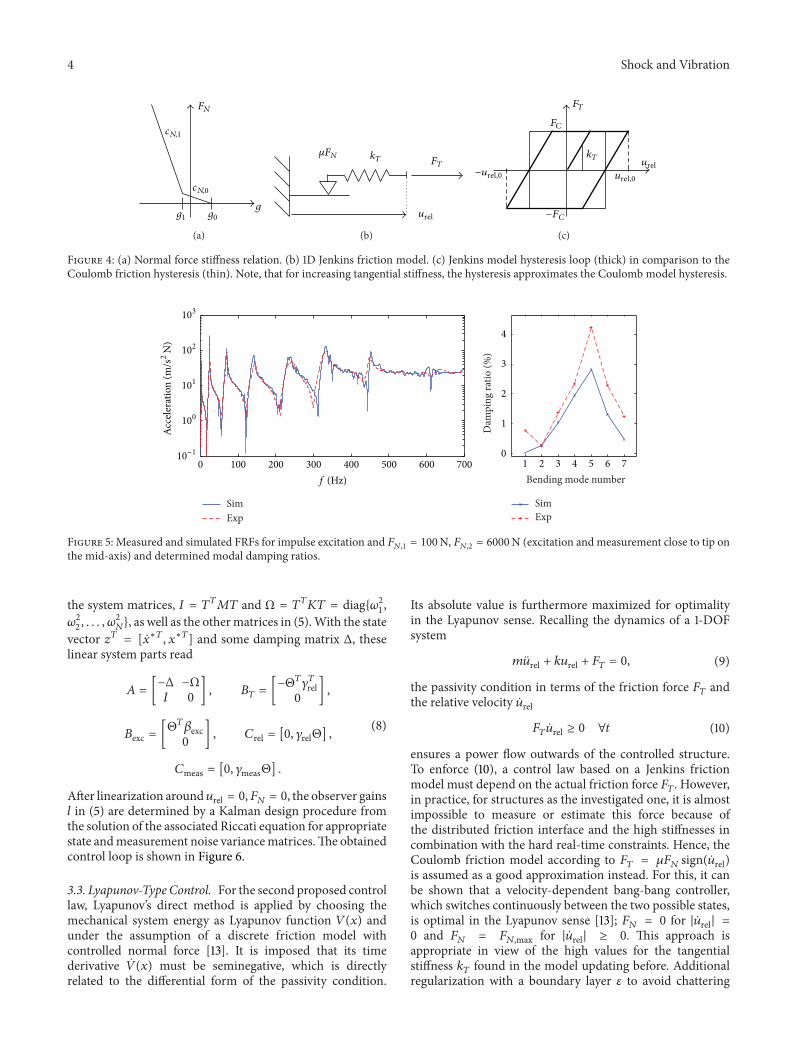
Constitutive equations are implemented for the normalcontact and the tangential contact in the interface by node-to-node contact elements The former is a bilinear stiffnessrelationship (Figure 4) that allows separation for a gap 119892 gt 119892
0
but penalizes penetration in two steps for 119892 lt 1198920and 119892 lt 119892
1
For the friction an elastoplastic model is used which can beseen as two-dimensional version of a Jenkins element modeldepicted in Figure 4 for the one-dimensional case that is aseries combination of a spring and a Coulomb element
The nonlinear system of (1) is solved with the Newmarkscheme and Newton equilibrium iterations at each fixed timestep Beforehand substructure model reduction techniquesare employed to reduce the dimensions of the system Forthat purpose an in-house simulation tool [14] is developedto facilitate general feedback control simulation which is notsupported by commercial FE codes The model parametersincluding the contact parameters are updated by comparisonof experimentally and numerically obtained FRFs (frequencyresponse function) with impulse hammer excitation thatcover a large range of constant clamping forces An exemplaryFRF is shown in Figure 5 where the nonlinear effects becomevisible by some unsymmetric peak forms (eg at 230Hz) andsome higher harmonics peaks From the FRF the dampingratios are identified for the bendingmodes see Figure 5Theyshow good agreement between simulation and experimentand significant damping is introduced by the friction damperif they are compared to the modal damping ratios of less than015 found without attached damper
3 Semiactive Vibration Control
Two controllers each consisting of an appropriate nonlinearcontrol law plus an observer to estimate nonmeasurablevariables required by the control are introduced in thefollowing The first control is denoted by hysteresis-optimalcontrol and ismotivated by experimental investigationsTheyshow that relatively simple dynamical friction models areoften capable of modeling the most dominant friction effectsin structures with local joints [16] Among others the Jenkinselement as depicted in Figure 4 has proven its usability forthat purpose and serves as base for the control derivation
31 Hysteresis-Optimal Control For that it is assumed thatthe dominant damping effects are located in the contact areaclose to the adaptive screw and can be modeled by a discretefriction model Then the dissipated work119882
119889due to friction
during one vibration cycle is maximized to find the controlFor the chosen model the dissipated energy
119882119889= 4(119906rel0 minus
119865119862
119896119879
)119865119862
with 119865119862= 120583119865119873 (2)
is maximized to yield the optimal normal force 119865119873
as afunction to the tangential contact stiffness 119896
119879 the friction
coefficient 120583 and the relative sliding oscillation amplitude119906rel0
119865119873= 119891 (119906rel0) =
119896119879119906rel0
2120583= 119896lowast
119879119906rel0 (3)
Note that similar algebraic expressions could be derived alsobased on hysteresis loops of more complex friction modelsinvolving more parameters Equation (3) is interpreted ascontrol law to adjust the normal force 119865
119873= 1198651198731
according toFigure 1 to the structural vibration tangential amplitude Therequired actual vibration displacement amplitude 119906rel0 can befound under the assumption of monofrequent displacement(with zero mean) by 119906rel0 asymp (1205872119879) int
119905
119905minus119879|119906rel|119889120591 from
Shock and Vibration 3
Piezoelectric stack
Strain gages
Force cell
Friction damperVibrating structure
Fixture
Piezoelectric force cell (only for Lyapunov-type control)Washers
InsulatorsShaker
x
Accelerometer
FN2 FN1
Figure 1 Sketch of the benchmark structure (steel 775mm length 40mm width and 3mm thickness) with adaptive friction damper beam(steel 160mm length 40mm width and 3mm thickness)
Figure 2 Photograph of the experimental setup with structuredamper beam piezoelectric stack force cell accelerometers andattached shaker stinger (cf Figure 1)
FN2FN1
Figure 3 Finite-element model (asymp30000 DOFs and 632 nodes incontact) in typical bending deformation with the two screws thatimpose the external clamping force pairs 119865
1198731and 119865
1198732
the estimated signal 119906rel The evaluation of the integral wouldneed large memory storage for the required integration timemuch larger than the largest vibration period of interesthence it is efficiently approximated by a first-order lagelement (119875119879
1) where the time constant119879
1prescribes how fast
the signal 119906rel0 follows a change in the vibration amplitude
32 Model-Based Design of Nonlinear Observer In generalthe required tangential displacement119906rel at the adaptive screwcannot be measured which makes the design of a nonlinearobserver necessary which estimates it from available mea-surements such as displacements strains or accelerationsand a simplified approximate simulation model withouthaving any information about the excitation forces
This model is derived by rigid connection of the damperbeam at one end (119865
1198732) and neglect of the normal contact
between damper and base structure instead appropriatespring elements are introduced in normal direction in somedistance around the adaptive screwThe relativemotion at the
adaptive screw is used for the output definition of rel Thenonlinear observer is of the form
Hereby the measurement output 119910meas denotes the velocitymeasurement obtained by integration of the accelerationin the experiment The estimated output rel replaces therequired variable 119906rel by the nonlinear control law (3) Asimple dynamic friction model 119891friction(sdot) is used to modelthe friction 119865
119879at the adaptive screw namely a regularized
Coulomb friction model
119865119879= 119891friction (
119906rel 119865119873) = 1205831198651198732
120587arctan (120572 119906rel) (6)
which depends on the relative velocity 119906rel with the regular-ization parameter 120572 determined by simulation studies The-oretically the use of more complex dynamic friction modelswould be of interest the hard real-time limitations imposedby the fixed-step time-integration in the experiment and theconsidered high frequencies forbid their application for theinvestigated problem The obtained estimation accuracy hasbeen verified in simulations that are also used to optimize theobserver The linear system parts in (5) are obtained froma simplified linear FE model after modal truncation plusa static correction step With the required output variablesmass and stiffness matrices 119872 119870 and load vector 119865exc thissimplified model reads with nonlinear inner force vector 119865
Solving the associated eigenvalue problem (119870 minus 1205962119872)120601 = 0
yields the eigenfrequencies 120596119896and eigenvectors 120601
119896(119896 isin N+)
which allows a modal truncation to the first 119873 importantbending modes by the transformation 119909 = 119879119909
lowast with 119879 =
[1206011 1206012 120601
119873] For a real-time application an observer of
low order is aspired Additional information to identifyimportant bending modes which are observable can beobtained by modal Gramians see [15 17] This transforms
4 Shock and Vibration
g
FN
cN1
cN0
g1 g0
(a)
120583FN kT FT
urel
(b)
FT
FC
kT
minusurel0 urel0
minusFC
urel
(c)
Figure 4 (a) Normal force stiffness relation (b) 1D Jenkins friction model (c) Jenkins model hysteresis loop (thick) in comparison to theCoulomb friction hysteresis (thin) Note that for increasing tangential stiffness the hysteresis approximates the Coulomb model hysteresis
0 100 200 300 400 500 600 700
SimExp
1 2 3 4 5 6 70
1
2
3
4
SimExp
Bending mode numberD
ampi
ng ra
tio (
)f (Hz)
Acce
lera
tion
(ms2
N)
103
102
101
100
10minus1
Figure 5 Measured and simulated FRFs for impulse excitation and 1198651198731
= 100N 1198651198732
= 6000N (excitation and measurement close to tip onthe mid-axis) and determined modal damping ratios
the system matrices 119868 = 119879119879119872119879 and Ω = 119879
119879119870119879 = diag1205962
1
1205962
2 120596
2
119873 as well as the othermatrices in (5)With the state
vector 119911119879 = [lowast119879 119909lowast119879] and some damping matrix Δ these
linear system parts read
119860 = [minusΔ minusΩ
119868 0] 119861
119879= [
minusΘ119879120574119879
rel0
]
119861exc = [Θ119879120573exc0
] 119862rel = [0 120574relΘ]
119862meas = [0 120574measΘ]
(8)
After linearization around119906rel = 0119865119873 = 0 the observer gains119897 in (5) are determined by a Kalman design procedure fromthe solution of the associated Riccati equation for appropriatestate andmeasurement noise variancematricesThe obtainedcontrol loop is shown in Figure 6
33 Lyapunov-Type Control For the second proposed controllaw Lyapunovrsquos direct method is applied by choosing themechanical system energy as Lyapunov function 119881(119909) andunder the assumption of a discrete friction model withcontrolled normal force [13] It is imposed that its timederivative (119909) must be seminegative which is directlyrelated to the differential form of the passivity condition
Its absolute value is furthermore maximized for optimalityin the Lyapunov sense Recalling the dynamics of a 1-DOFsystem
the passivity condition in terms of the friction force 119865119879and
the relative velocity rel
119865119879rel ge 0 forall119905 (10)
ensures a power flow outwards of the controlled structureTo enforce (10) a control law based on a Jenkins frictionmodel must depend on the actual friction force 119865
119879 However
in practice for structures as the investigated one it is almostimpossible to measure or estimate this force because ofthe distributed friction interface and the high stiffnesses incombination with the hard real-time constraints Hence theCoulomb friction model according to 119865
119879= 120583119865119873sign(rel)
is assumed as a good approximation instead For this it canbe shown that a velocity-dependent bang-bang controllerwhich switches continuously between the two possible statesis optimal in the Lyapunov sense [13] 119865
119873= 0 for |rel| =
0 and 119865119873
= 119865119873max for |rel| ge 0 This approach is
appropriate in view of the high values for the tangentialstiffness 119896
119879found in the model updating before Additional
regularization with a boundary layer 120576 to avoid chattering
Shock and Vibration 5
Vibrating flexible structure
Control
High-voltageamplifier
ObserverControl lawPI force control
UP
Uc
UP = KPe + KIinted120591e minus
+
FN
FNmeas
urel0 = f(urel0 urel)
FN = f(urel0)
urelEq (5)
ymeasymeas = Clowastz
urel = Clowastrel z
Figure 6 Closed control loop with hysteresis-optimal control law
20 22 24 26 28 300
100
200
300
Frequency (Hz)
Am
plitu
de (m
s2
N)
(a) Mode 2 119865exc0 = 04N
Frequency (Hz)60 65 70 75
0
20
40
60
80
100
Am
plitu
de (m
s2
N)
(b) Mode 3 119865exc0 = 3N
Frequency (Hz)130 135 140 145 150 155 160
0
20
40
60
80
100
Am
plitu
de (m
s2
N)
(c) Mode 4 119865exc0 = 3N
Frequency (Hz)20 22 24 26 28 30
0100200300400500600
Am
plitu
de (m
s2
N)
(d) Mode 2 119865exc0 = 04N
Frequency (Hz)60 65 70 75
020406080
100120
Am
plitu
de (m
s2
N)
(e) Mode 3 119865exc0 = 3N
Frequency (Hz)130 135 140 145 150 155 1600
50
100
150
200
250
Am
plitu
de (m
s2
N)
(f) Mode 4 119865exc0 = 3N
Figure 7 Hysteresis-optimal control measured (top) and simulated (bottom) accelerance FRFs for controlled sine-sweep excitation with(solid) and without (dashed) control (119896lowast
119879= 25 sdot 10
7Nm)
effects and introduction of the minimal normal force yieldsthe suboptimal law
119865119873=
max1003816100381610038161003816rel
1003816100381610038161003816
120576119865119873max 119865119873min for 1003816100381610038161003816rel
1003816100381610038161003816 lt 120576
119865119873max for 1003816100381610038161003816rel
1003816100381610038161003816 ge 120576
(11)
Again the required tangential relative motion must beestimated by the previously introduced observer which nowestimated the relative velocity rel instead of the displacement119906rel Note that theminimal andmaximal normal forces119865
119873minand 119865
119873max are determined by the mechanical properties ofthe adaptive screw
4 Experiments and Simulation Results
The proposed controls are investigated for the benchmarkstructure with a damper beam at 119909
119889= 0545m away from
the fixture For this position significant relative displacementbetween structure and damper is expected for the bendingmodes 3 4 and higher For mode 2 much less relative motionis expectedwhich explains the small damping values obtainedin the experiment and simulations for example for thepassive results in Figure 5 The first mode is not consideredbecause it cannot be excited by the available shaker Forevaluation accelerated FRFs from the excitation force (at 119909 =0325m) to the measured acceleration (at 119909 = 045m) arecompared
41 Controller Implementation A dSpace system runningat 21 kHz sampling frequency is used for the real-timeimplementationThe observer is designed based on 7 normalmodes and uses the out-of-plane tip acceleration at 119909 =
0765m as measurement variable 119910meas In the experimentthe prescribed force 119865
119873for the adaptive screw from (3) or
6 Shock and Vibration
Frequency (Hz)20 22 24 26 28 30
0
100
200
300
Am
plitu
de (m
s2
N)
(a) Mode 2 119865exc0 = 04N
Frequency (Hz)60 65 70 75
0
20
40
60
80
100
Am
plitu
de (m
s2
N)
(b) Mode 3 119865exc0 = 3N
Frequency (Hz)130 135 140 145 150 155 1600
20
40
60
80
100
Am
plitu
de (m
s2
N)
(c) Mode 4 119865exc0 = 3N
Frequency (Hz)20 22 24 26 28 30
0100200300400500600
Am
plitu
de (m
s2
N)
(d) Mode 2 119865exc0 = 04N
Frequency (Hz)60 65 70 75
020406080
100120
Am
plitu
de (m
s2
N)
(e) Mode 3 119865exc0 = 3N
Frequency (Hz)130 135 140 145 150 155 1600
50
100
150
200
250
Am
plitu
de (m
s2
N)
(f) Mode 4 119865exc0 = 3N
Figure 8 Lyapunov-type control measured (top) and simulated (bottom) accelerance FRFs for controlled sine-sweep excitation with (solid)and without (dashed) control (120576 = 1200ms)
(11) must be tracked by an underlying force feedback controlloop to compensate nonlinearities large-signal piezoelectriceffects and creep effects in the screw threads as well asdecrease the inertia forces of the actuator and sensor massesdue to the structural vibrations For that a tracking controlleris employed which is combined from a feedforward termderived from the static actuator voltage-force relationshipand a PID feedback control of the measured force Theobtained actuator signal 119880
119875is filtered by a 30 kHz low-pass
filter to decrease the digitization noise before it is amplifiedfor the piezoelectric stack actuator To maximize the stiffnessof the clamping of the piezoelectric actuators determiningthe achievable stroke [2] strain gages directly embedded inthe bolt shaft (see Figure 6) measure the actual force insteadof strain-gage based ring force cells that would significantlyweaken the configuration The applicable actuator stroke liesbetween 119865
119873min = 40N and 119865119873max asymp 600N
For the Lyapunov-type control a piezoelectric force cell ofhigh sensitivity and bandwidth is added (cf Figure 2) becauseits high actuation dynamics requires a very high controlbandwidth which is difficult to realize with strain-gage basedforce measurements due to the found signal-to-noise ratioand delays originating from the necessary amplifiers
42 Shaker Test Setup with Excitation Force Control Fornonlinear mechanical structures comparing FRFs requiresspecial care because the obtained FRFs are nonlinear Morespecifically their resonance frequencies peak amplitudesand peak forms depend on the excitation signal as well asamplitudes Consequently the amplitude is controlled duringsine sweep measurements to make the excitation indepen-dent of the structural impedance for consistent comparisons
Very low sweep velocities (01 Hzs) are employed to obtainsteady-state conditions which approximate step-sine testingand to avoid interaction between the interesting effects ofthe semiactive structural control and the shaker control Dueto the very small relative displacements outside resonancesthe control is only effective close to resonances which allowsrestricting the evaluation around the resonance frequenciesto save simulation and measurement time
In Figures 7 and 8 FRFs with and without semiactivecontrol are shown for some typical excitation amplitudesfor the two control concepts Similar results are obtainedfor other amplitudes It can always be seen that the controlstrongly reduces the resonance amplitudes ofmultiplemodesHowever for the second mode the obtained damping is quitesmall in the active as well as the passive caseThis is due to theslight curvature of the beam at the lower modes which resultsin a small relative motion in the interface Additionally thisfact implies that the obtained efficiency of the damper isdependent on its position
In the passive case the minimal possible force 119865119873
=
119865119873min is applied to the adaptive screw which still introduces
significant structural damping compared to the case withoutattached damper Experiments and simulation additionallyprove that the semiactive control never decreases the passivedamping effect at lower excitation amplitudes Generally theagreement obtained between experiment and simulationsis rated very good in view of the well-known difficultiesencountered in the prediction of nonlinear damping of struc-tures especially for distributed friction with inhomogeneousnormal contact pressure distribution Furthermore someimperfections of the excitation control cannot be avoidedas well as some changes in the contact parameters TheLyapunov-type control achieves higher vibration reduction
Shock and Vibration 7
than the hysteresis-optimal one in both experiments andsimulations especially at smaller vibration amplitudes It isalso suited to suppress broadband vibrations and relativelyrobust to errors in the estimation but as a drawback its highdynamical actuation requires more power Advantageouslythe hysteresis-optimal control could be implemented withlow dynamical actuators for example of different actuationprinciples
5 Conclusion
Multimodal semiactive vibration controllers that adapt thenormal force applied to friction damper beams by piezoelec-tric stack actuators are investigated for a generic benchmarkstructure in experiments and simulations They are shown toefficiently damp structural resonances for different excitationamplitudes and vibration modes Which of the investi-gated controller concepts suits best for a certain applicationdepends mainly on the actuator principle the power consid-erations and whether the excitation being rather broadbandor narrowband Based on the results of the beam experimentthe proposed friction damper is used to reduce the vibrationsof machine tools [18]
Conflict of Interests
The authors declare that there is no conflict of interestsregarding the publication of this paper
Acknowledgment
The support of the DFG (German Research Foundation) withProject SPP 1156 is gratefully acknowledged
References
[1] M J Balas ldquoFeedback control of flexible systemsrdquo IEEE Trans-actions on Automatic Control vol AC-23 no 4 pp 673ndash6791978
[2] C Fuller S Elliott and P Nelson Active Control of VibrationAcademic Press New York NY USA 1996
[3] P Dupont P Kasturi and A Stokes ldquoSemi-active control offriction dampersrdquo Journal of Sound and Vibration vol 202 no2 pp 203ndash218 1997
[4] L M Jansen and S J Dyke ldquoSemiactive control strategiesfor MR dampers a comparative studyrdquo Journal of EngineeringMechanics vol 126 no 8 pp 795ndash803 2000
[5] O E Ozbulut M Bitaraf and S Hurlebaus ldquoAdaptive controlof base-isolated structures against near-field earthquakes usingvariable friction dampersrdquo Engineering Structures vol 33 no12 pp 3143ndash3154 2011
[6] S Nagarajaiah S Narasimhan A Agrawal and P Tan ldquoSemi-active Lyapunov controller for phase II seismic isolated highwaybridge benchmarkrdquo inProceedings of the Structures Congress pp1ndash10 2006
[7] F Nitzsche D G Zimcik V K Wickramasinghe and C YongldquoControl laws for an active tunable vibration absorber designedfor rotor blade damping augmentationrdquo Aeronautical Journalvol 108 no 1079 pp 35ndash42 2004
[8] W N Patten CMo J Kuehn and J Lee ldquoA primer on design ofsemiactive vibration absorbers (SAVA)rdquo Journal of EngineeringMechanics vol 124 no 1 pp 61ndash67 1998
[9] H Li J Li and G Song ldquoImproved suboptimal Bang-Bangcontrol of aseismic buildings with variable friction dampersrdquoActa Mechanica Sinica vol 23 no 1 pp 101ndash109 2007
[10] M D Symans and M C Constantinou ldquoSeismic testing ofa building structure with a semi-active fluid damper controlsystemrdquo Earthquake Engineering and Structural Dynamics vol26 no 7 pp 759ndash777 1997
[11] M Unsal C Niezrecki and C Crane III A New Semi-ActivePiezoelectric-Based Friction Damper Department of Mechani-cal Engineering University of Florida 2007
[12] J S Lane A A Ferri and B S Heck ldquoVibration control usingsemi-active friction dampingrdquo in Proceedings of the WinterAnnualMeeting of the American Society of Mechanical Engineers(ASME 92) vol 49 pp 165ndash171 November 1992
[13] R Nitsche and L Gaul ldquoLyapunov design of damping con-trollersrdquoArchive of AppliedMechanics vol 72 no 11-12 pp 865ndash874 2003
[14] J Becker and L Gaul ldquoCMS methods for efficient dampingprediction for structures with frictionrdquo in Proceedings of the26th Conference and Exposition on Structural Dynamics (IMAC-XXVI rsquo08) Orlando Fla USA February 2008
[15] J Becker Semi-active control of friction dampers and feedforwardtracking control design for structural vibration reduction [PhDthesis] University of Stuttgart Der Andere 2009
[16] L Gaul and R Nitsche ldquoThe role of friction in mechanicaljointsrdquo Applied Mechanics Reviews vol 54 no 2 pp 93ndash1052001
[17] W K GawronskiDynamics and Control of Structures Mechan-ical Engineering Series Springer New York NY USA 1998
control of the normal force between a main structureand attached damper exploiting dry friction damping areinvestigatedThe focus of this contribution is to damp severalstructural modes of beam
2 System Representation
21 Beam Structure A beam-like friction damper elementis attached to a beam-like metal benchmark structure by anormal screw and an adaptive screwThe principle is depictedschematically in Figure 1 a picture of the experimental real-ization is shown in Figure 2 One screw is strongly tightenedwith a normal force of 119865
1198732= 6000N whereas the normal
force 1198651198731
of the adaptive screw can be controlled by meansof a piezoelectric ring stack actuator For that purpose thecontrol measures the acceleration close to the tip
22 Finite-Element Modeling The structure is discretized bythe finite-element (FE) method using ANSYS (Figure 3) Thebeam and the friction damper are modeled as independentsubstructures with solid elements having quadratic shapefunctions The mesh size is chosen in accordance withShannonrsquos theorem At the interface identical meshes areused to enable the application of a node-to-node contactformulation After assembly the established system matricesin terms of mass and stiffness are transferred to MATLABusing the StructuralDynamics ToolboxThis procedure offersflexibility for applying different model reduction as well asapplying control techniques Reducedmodels with aminimaltruncation error were found in a previous investigation andfor more details it is referred to [14 15] at this point
In a generic way the discretized structural dynamics ofthe two substructures namely the main structure and theattached friction damper beam are given by
[119872(1)
0
0 119872(2)] + [
119870(1)
0
0 119870(2)]119909 + [
[
119861(1)
119879
119861(2)
119879
]
]
119865119888
119879+ [
[
119861(1)
119873
119861(2)
119873
]
]
119865119888
119873
= 119861[1198651198731
1198651198732
] + 119865exc
(1)
where the nodal normal contact forces 119865119888119873
and tangentialfriction forces119865119888
119879act as internal forces on the contact interface
between main structure and damper beam On the right-hand side the external forces appear namely the two pairs ofclamping forces 119865
1198731 1198651198732
and dynamic excitation loads 119865exc(later 119865
1198731is controlled)
Constitutive equations are implemented for the normalcontact and the tangential contact in the interface by node-to-node contact elements The former is a bilinear stiffnessrelationship (Figure 4) that allows separation for a gap 119892 gt 119892
0
but penalizes penetration in two steps for 119892 lt 1198920and 119892 lt 119892
1
For the friction an elastoplastic model is used which can beseen as two-dimensional version of a Jenkins element modeldepicted in Figure 4 for the one-dimensional case that is aseries combination of a spring and a Coulomb element
The nonlinear system of (1) is solved with the Newmarkscheme and Newton equilibrium iterations at each fixed timestep Beforehand substructure model reduction techniquesare employed to reduce the dimensions of the system Forthat purpose an in-house simulation tool [14] is developedto facilitate general feedback control simulation which is notsupported by commercial FE codes The model parametersincluding the contact parameters are updated by comparisonof experimentally and numerically obtained FRFs (frequencyresponse function) with impulse hammer excitation thatcover a large range of constant clamping forces An exemplaryFRF is shown in Figure 5 where the nonlinear effects becomevisible by some unsymmetric peak forms (eg at 230Hz) andsome higher harmonics peaks From the FRF the dampingratios are identified for the bendingmodes see Figure 5Theyshow good agreement between simulation and experimentand significant damping is introduced by the friction damperif they are compared to the modal damping ratios of less than015 found without attached damper
3 Semiactive Vibration Control
Two controllers each consisting of an appropriate nonlinearcontrol law plus an observer to estimate nonmeasurablevariables required by the control are introduced in thefollowing The first control is denoted by hysteresis-optimalcontrol and ismotivated by experimental investigationsTheyshow that relatively simple dynamical friction models areoften capable of modeling the most dominant friction effectsin structures with local joints [16] Among others the Jenkinselement as depicted in Figure 4 has proven its usability forthat purpose and serves as base for the control derivation
31 Hysteresis-Optimal Control For that it is assumed thatthe dominant damping effects are located in the contact areaclose to the adaptive screw and can be modeled by a discretefriction model Then the dissipated work119882
119889due to friction
during one vibration cycle is maximized to find the controlFor the chosen model the dissipated energy
119882119889= 4(119906rel0 minus
119865119862
119896119879
)119865119862
with 119865119862= 120583119865119873 (2)
is maximized to yield the optimal normal force 119865119873
as afunction to the tangential contact stiffness 119896
119879 the friction
coefficient 120583 and the relative sliding oscillation amplitude119906rel0
119865119873= 119891 (119906rel0) =
119896119879119906rel0
2120583= 119896lowast
119879119906rel0 (3)
Note that similar algebraic expressions could be derived alsobased on hysteresis loops of more complex friction modelsinvolving more parameters Equation (3) is interpreted ascontrol law to adjust the normal force 119865
119873= 1198651198731
according toFigure 1 to the structural vibration tangential amplitude Therequired actual vibration displacement amplitude 119906rel0 can befound under the assumption of monofrequent displacement(with zero mean) by 119906rel0 asymp (1205872119879) int
119905
119905minus119879|119906rel|119889120591 from
Shock and Vibration 3
Piezoelectric stack
Strain gages
Force cell
Friction damperVibrating structure
Fixture
Piezoelectric force cell (only for Lyapunov-type control)Washers
InsulatorsShaker
x
Accelerometer
FN2 FN1
Figure 1 Sketch of the benchmark structure (steel 775mm length 40mm width and 3mm thickness) with adaptive friction damper beam(steel 160mm length 40mm width and 3mm thickness)
Figure 2 Photograph of the experimental setup with structuredamper beam piezoelectric stack force cell accelerometers andattached shaker stinger (cf Figure 1)
FN2FN1
Figure 3 Finite-element model (asymp30000 DOFs and 632 nodes incontact) in typical bending deformation with the two screws thatimpose the external clamping force pairs 119865
1198731and 119865
1198732
the estimated signal 119906rel The evaluation of the integral wouldneed large memory storage for the required integration timemuch larger than the largest vibration period of interesthence it is efficiently approximated by a first-order lagelement (119875119879
1) where the time constant119879
1prescribes how fast
the signal 119906rel0 follows a change in the vibration amplitude
32 Model-Based Design of Nonlinear Observer In generalthe required tangential displacement119906rel at the adaptive screwcannot be measured which makes the design of a nonlinearobserver necessary which estimates it from available mea-surements such as displacements strains or accelerationsand a simplified approximate simulation model withouthaving any information about the excitation forces
This model is derived by rigid connection of the damperbeam at one end (119865
1198732) and neglect of the normal contact
between damper and base structure instead appropriatespring elements are introduced in normal direction in somedistance around the adaptive screwThe relativemotion at the
adaptive screw is used for the output definition of rel Thenonlinear observer is of the form
Hereby the measurement output 119910meas denotes the velocitymeasurement obtained by integration of the accelerationin the experiment The estimated output rel replaces therequired variable 119906rel by the nonlinear control law (3) Asimple dynamic friction model 119891friction(sdot) is used to modelthe friction 119865
119879at the adaptive screw namely a regularized
Coulomb friction model
119865119879= 119891friction (
119906rel 119865119873) = 1205831198651198732
120587arctan (120572 119906rel) (6)
which depends on the relative velocity 119906rel with the regular-ization parameter 120572 determined by simulation studies The-oretically the use of more complex dynamic friction modelswould be of interest the hard real-time limitations imposedby the fixed-step time-integration in the experiment and theconsidered high frequencies forbid their application for theinvestigated problem The obtained estimation accuracy hasbeen verified in simulations that are also used to optimize theobserver The linear system parts in (5) are obtained froma simplified linear FE model after modal truncation plusa static correction step With the required output variablesmass and stiffness matrices 119872 119870 and load vector 119865exc thissimplified model reads with nonlinear inner force vector 119865
Solving the associated eigenvalue problem (119870 minus 1205962119872)120601 = 0
yields the eigenfrequencies 120596119896and eigenvectors 120601
119896(119896 isin N+)
which allows a modal truncation to the first 119873 importantbending modes by the transformation 119909 = 119879119909
lowast with 119879 =
[1206011 1206012 120601
119873] For a real-time application an observer of
low order is aspired Additional information to identifyimportant bending modes which are observable can beobtained by modal Gramians see [15 17] This transforms
4 Shock and Vibration
g
FN
cN1
cN0
g1 g0
(a)
120583FN kT FT
urel
(b)
FT
FC
kT
minusurel0 urel0
minusFC
urel
(c)
Figure 4 (a) Normal force stiffness relation (b) 1D Jenkins friction model (c) Jenkins model hysteresis loop (thick) in comparison to theCoulomb friction hysteresis (thin) Note that for increasing tangential stiffness the hysteresis approximates the Coulomb model hysteresis
0 100 200 300 400 500 600 700
SimExp
1 2 3 4 5 6 70
1
2
3
4
SimExp
Bending mode numberD
ampi
ng ra
tio (
)f (Hz)
Acce
lera
tion
(ms2
N)
103
102
101
100
10minus1
Figure 5 Measured and simulated FRFs for impulse excitation and 1198651198731
= 100N 1198651198732
= 6000N (excitation and measurement close to tip onthe mid-axis) and determined modal damping ratios
the system matrices 119868 = 119879119879119872119879 and Ω = 119879
119879119870119879 = diag1205962
1
1205962
2 120596
2
119873 as well as the othermatrices in (5)With the state
vector 119911119879 = [lowast119879 119909lowast119879] and some damping matrix Δ these
linear system parts read
119860 = [minusΔ minusΩ
119868 0] 119861
119879= [
minusΘ119879120574119879
rel0
]
119861exc = [Θ119879120573exc0
] 119862rel = [0 120574relΘ]
119862meas = [0 120574measΘ]
(8)
After linearization around119906rel = 0119865119873 = 0 the observer gains119897 in (5) are determined by a Kalman design procedure fromthe solution of the associated Riccati equation for appropriatestate andmeasurement noise variancematricesThe obtainedcontrol loop is shown in Figure 6
33 Lyapunov-Type Control For the second proposed controllaw Lyapunovrsquos direct method is applied by choosing themechanical system energy as Lyapunov function 119881(119909) andunder the assumption of a discrete friction model withcontrolled normal force [13] It is imposed that its timederivative (119909) must be seminegative which is directlyrelated to the differential form of the passivity condition
Its absolute value is furthermore maximized for optimalityin the Lyapunov sense Recalling the dynamics of a 1-DOFsystem
the passivity condition in terms of the friction force 119865119879and
the relative velocity rel
119865119879rel ge 0 forall119905 (10)
ensures a power flow outwards of the controlled structureTo enforce (10) a control law based on a Jenkins frictionmodel must depend on the actual friction force 119865
119879 However
in practice for structures as the investigated one it is almostimpossible to measure or estimate this force because ofthe distributed friction interface and the high stiffnesses incombination with the hard real-time constraints Hence theCoulomb friction model according to 119865
119879= 120583119865119873sign(rel)
is assumed as a good approximation instead For this it canbe shown that a velocity-dependent bang-bang controllerwhich switches continuously between the two possible statesis optimal in the Lyapunov sense [13] 119865
119873= 0 for |rel| =
0 and 119865119873
= 119865119873max for |rel| ge 0 This approach is
appropriate in view of the high values for the tangentialstiffness 119896
119879found in the model updating before Additional
regularization with a boundary layer 120576 to avoid chattering
Shock and Vibration 5
Vibrating flexible structure
Control
High-voltageamplifier
ObserverControl lawPI force control
UP
Uc
UP = KPe + KIinted120591e minus
+
FN
FNmeas
urel0 = f(urel0 urel)
FN = f(urel0)
urelEq (5)
ymeasymeas = Clowastz
urel = Clowastrel z
Figure 6 Closed control loop with hysteresis-optimal control law
20 22 24 26 28 300
100
200
300
Frequency (Hz)
Am
plitu
de (m
s2
N)
(a) Mode 2 119865exc0 = 04N
Frequency (Hz)60 65 70 75
0
20
40
60
80
100
Am
plitu
de (m
s2
N)
(b) Mode 3 119865exc0 = 3N
Frequency (Hz)130 135 140 145 150 155 160
0
20
40
60
80
100
Am
plitu
de (m
s2
N)
(c) Mode 4 119865exc0 = 3N
Frequency (Hz)20 22 24 26 28 30
0100200300400500600
Am
plitu
de (m
s2
N)
(d) Mode 2 119865exc0 = 04N
Frequency (Hz)60 65 70 75
020406080
100120
Am
plitu
de (m
s2
N)
(e) Mode 3 119865exc0 = 3N
Frequency (Hz)130 135 140 145 150 155 1600
50
100
150
200
250
Am
plitu
de (m
s2
N)
(f) Mode 4 119865exc0 = 3N
Figure 7 Hysteresis-optimal control measured (top) and simulated (bottom) accelerance FRFs for controlled sine-sweep excitation with(solid) and without (dashed) control (119896lowast
119879= 25 sdot 10
7Nm)
effects and introduction of the minimal normal force yieldsthe suboptimal law
119865119873=
max1003816100381610038161003816rel
1003816100381610038161003816
120576119865119873max 119865119873min for 1003816100381610038161003816rel
1003816100381610038161003816 lt 120576
119865119873max for 1003816100381610038161003816rel
1003816100381610038161003816 ge 120576
(11)
Again the required tangential relative motion must beestimated by the previously introduced observer which nowestimated the relative velocity rel instead of the displacement119906rel Note that theminimal andmaximal normal forces119865
119873minand 119865
119873max are determined by the mechanical properties ofthe adaptive screw
4 Experiments and Simulation Results
The proposed controls are investigated for the benchmarkstructure with a damper beam at 119909
119889= 0545m away from
the fixture For this position significant relative displacementbetween structure and damper is expected for the bendingmodes 3 4 and higher For mode 2 much less relative motionis expectedwhich explains the small damping values obtainedin the experiment and simulations for example for thepassive results in Figure 5 The first mode is not consideredbecause it cannot be excited by the available shaker Forevaluation accelerated FRFs from the excitation force (at 119909 =0325m) to the measured acceleration (at 119909 = 045m) arecompared
41 Controller Implementation A dSpace system runningat 21 kHz sampling frequency is used for the real-timeimplementationThe observer is designed based on 7 normalmodes and uses the out-of-plane tip acceleration at 119909 =
0765m as measurement variable 119910meas In the experimentthe prescribed force 119865
119873for the adaptive screw from (3) or
6 Shock and Vibration
Frequency (Hz)20 22 24 26 28 30
0
100
200
300
Am
plitu
de (m
s2
N)
(a) Mode 2 119865exc0 = 04N
Frequency (Hz)60 65 70 75
0
20
40
60
80
100
Am
plitu
de (m
s2
N)
(b) Mode 3 119865exc0 = 3N
Frequency (Hz)130 135 140 145 150 155 1600
20
40
60
80
100
Am
plitu
de (m
s2
N)
(c) Mode 4 119865exc0 = 3N
Frequency (Hz)20 22 24 26 28 30
0100200300400500600
Am
plitu
de (m
s2
N)
(d) Mode 2 119865exc0 = 04N
Frequency (Hz)60 65 70 75
020406080
100120
Am
plitu
de (m
s2
N)
(e) Mode 3 119865exc0 = 3N
Frequency (Hz)130 135 140 145 150 155 1600
50
100
150
200
250
Am
plitu
de (m
s2
N)
(f) Mode 4 119865exc0 = 3N
Figure 8 Lyapunov-type control measured (top) and simulated (bottom) accelerance FRFs for controlled sine-sweep excitation with (solid)and without (dashed) control (120576 = 1200ms)
(11) must be tracked by an underlying force feedback controlloop to compensate nonlinearities large-signal piezoelectriceffects and creep effects in the screw threads as well asdecrease the inertia forces of the actuator and sensor massesdue to the structural vibrations For that a tracking controlleris employed which is combined from a feedforward termderived from the static actuator voltage-force relationshipand a PID feedback control of the measured force Theobtained actuator signal 119880
119875is filtered by a 30 kHz low-pass
filter to decrease the digitization noise before it is amplifiedfor the piezoelectric stack actuator To maximize the stiffnessof the clamping of the piezoelectric actuators determiningthe achievable stroke [2] strain gages directly embedded inthe bolt shaft (see Figure 6) measure the actual force insteadof strain-gage based ring force cells that would significantlyweaken the configuration The applicable actuator stroke liesbetween 119865
119873min = 40N and 119865119873max asymp 600N
For the Lyapunov-type control a piezoelectric force cell ofhigh sensitivity and bandwidth is added (cf Figure 2) becauseits high actuation dynamics requires a very high controlbandwidth which is difficult to realize with strain-gage basedforce measurements due to the found signal-to-noise ratioand delays originating from the necessary amplifiers
42 Shaker Test Setup with Excitation Force Control Fornonlinear mechanical structures comparing FRFs requiresspecial care because the obtained FRFs are nonlinear Morespecifically their resonance frequencies peak amplitudesand peak forms depend on the excitation signal as well asamplitudes Consequently the amplitude is controlled duringsine sweep measurements to make the excitation indepen-dent of the structural impedance for consistent comparisons
Very low sweep velocities (01 Hzs) are employed to obtainsteady-state conditions which approximate step-sine testingand to avoid interaction between the interesting effects ofthe semiactive structural control and the shaker control Dueto the very small relative displacements outside resonancesthe control is only effective close to resonances which allowsrestricting the evaluation around the resonance frequenciesto save simulation and measurement time
In Figures 7 and 8 FRFs with and without semiactivecontrol are shown for some typical excitation amplitudesfor the two control concepts Similar results are obtainedfor other amplitudes It can always be seen that the controlstrongly reduces the resonance amplitudes ofmultiplemodesHowever for the second mode the obtained damping is quitesmall in the active as well as the passive caseThis is due to theslight curvature of the beam at the lower modes which resultsin a small relative motion in the interface Additionally thisfact implies that the obtained efficiency of the damper isdependent on its position
In the passive case the minimal possible force 119865119873
=
119865119873min is applied to the adaptive screw which still introduces
significant structural damping compared to the case withoutattached damper Experiments and simulation additionallyprove that the semiactive control never decreases the passivedamping effect at lower excitation amplitudes Generally theagreement obtained between experiment and simulationsis rated very good in view of the well-known difficultiesencountered in the prediction of nonlinear damping of struc-tures especially for distributed friction with inhomogeneousnormal contact pressure distribution Furthermore someimperfections of the excitation control cannot be avoidedas well as some changes in the contact parameters TheLyapunov-type control achieves higher vibration reduction
Shock and Vibration 7
than the hysteresis-optimal one in both experiments andsimulations especially at smaller vibration amplitudes It isalso suited to suppress broadband vibrations and relativelyrobust to errors in the estimation but as a drawback its highdynamical actuation requires more power Advantageouslythe hysteresis-optimal control could be implemented withlow dynamical actuators for example of different actuationprinciples
5 Conclusion
Multimodal semiactive vibration controllers that adapt thenormal force applied to friction damper beams by piezoelec-tric stack actuators are investigated for a generic benchmarkstructure in experiments and simulations They are shown toefficiently damp structural resonances for different excitationamplitudes and vibration modes Which of the investi-gated controller concepts suits best for a certain applicationdepends mainly on the actuator principle the power consid-erations and whether the excitation being rather broadbandor narrowband Based on the results of the beam experimentthe proposed friction damper is used to reduce the vibrationsof machine tools [18]
Conflict of Interests
The authors declare that there is no conflict of interestsregarding the publication of this paper
Acknowledgment
The support of the DFG (German Research Foundation) withProject SPP 1156 is gratefully acknowledged
References
[1] M J Balas ldquoFeedback control of flexible systemsrdquo IEEE Trans-actions on Automatic Control vol AC-23 no 4 pp 673ndash6791978
[2] C Fuller S Elliott and P Nelson Active Control of VibrationAcademic Press New York NY USA 1996
[3] P Dupont P Kasturi and A Stokes ldquoSemi-active control offriction dampersrdquo Journal of Sound and Vibration vol 202 no2 pp 203ndash218 1997
[4] L M Jansen and S J Dyke ldquoSemiactive control strategiesfor MR dampers a comparative studyrdquo Journal of EngineeringMechanics vol 126 no 8 pp 795ndash803 2000
[5] O E Ozbulut M Bitaraf and S Hurlebaus ldquoAdaptive controlof base-isolated structures against near-field earthquakes usingvariable friction dampersrdquo Engineering Structures vol 33 no12 pp 3143ndash3154 2011
[6] S Nagarajaiah S Narasimhan A Agrawal and P Tan ldquoSemi-active Lyapunov controller for phase II seismic isolated highwaybridge benchmarkrdquo inProceedings of the Structures Congress pp1ndash10 2006
[7] F Nitzsche D G Zimcik V K Wickramasinghe and C YongldquoControl laws for an active tunable vibration absorber designedfor rotor blade damping augmentationrdquo Aeronautical Journalvol 108 no 1079 pp 35ndash42 2004
[8] W N Patten CMo J Kuehn and J Lee ldquoA primer on design ofsemiactive vibration absorbers (SAVA)rdquo Journal of EngineeringMechanics vol 124 no 1 pp 61ndash67 1998
[9] H Li J Li and G Song ldquoImproved suboptimal Bang-Bangcontrol of aseismic buildings with variable friction dampersrdquoActa Mechanica Sinica vol 23 no 1 pp 101ndash109 2007
[10] M D Symans and M C Constantinou ldquoSeismic testing ofa building structure with a semi-active fluid damper controlsystemrdquo Earthquake Engineering and Structural Dynamics vol26 no 7 pp 759ndash777 1997
[11] M Unsal C Niezrecki and C Crane III A New Semi-ActivePiezoelectric-Based Friction Damper Department of Mechani-cal Engineering University of Florida 2007
[12] J S Lane A A Ferri and B S Heck ldquoVibration control usingsemi-active friction dampingrdquo in Proceedings of the WinterAnnualMeeting of the American Society of Mechanical Engineers(ASME 92) vol 49 pp 165ndash171 November 1992
[13] R Nitsche and L Gaul ldquoLyapunov design of damping con-trollersrdquoArchive of AppliedMechanics vol 72 no 11-12 pp 865ndash874 2003
[14] J Becker and L Gaul ldquoCMS methods for efficient dampingprediction for structures with frictionrdquo in Proceedings of the26th Conference and Exposition on Structural Dynamics (IMAC-XXVI rsquo08) Orlando Fla USA February 2008
[15] J Becker Semi-active control of friction dampers and feedforwardtracking control design for structural vibration reduction [PhDthesis] University of Stuttgart Der Andere 2009
[16] L Gaul and R Nitsche ldquoThe role of friction in mechanicaljointsrdquo Applied Mechanics Reviews vol 54 no 2 pp 93ndash1052001
[17] W K GawronskiDynamics and Control of Structures Mechan-ical Engineering Series Springer New York NY USA 1998