The seismic behavior of short circular reinforced concrete columns was studied by testing seven columns retrofitted withprestressing steel wire (PSW), subjected to combined constant axial compression and lateral cyclic load. The main test parameterswere configuration index of PSW, prestressing level of PSW, and axial compression ratio. An analysis and discussion of the test resultsincluding failure mode, hysteresis curves, skeleton curves, ductility, and degradation of stiffness was done. The results show thatthe seismic performance of the retrofitted specimens could be effectively enhanced even if the axial compression ratio of columnsreached 0.81.The ductility index and the energy absorption capacity of the retrofitted specimens increase with the prestressing levelof PSW. The formulas for calculating shear capacity of RC short columns strengthened with PSW were proposed which may beuseful for future engineering designs and researches.
1. Introduction
Many of the catastrophic failures of bridges or frame struc-tures that occurred during the past earthquakes were due tothe failure of one or more of the RC columns. Shear damagesustained by short and stubby columns is often responsiblefor the collapse of the entire structure.The deficiencies in theseismic shear resistance may be attributed to the old designprovisions, which resulted in lack of sufficient transversereinforcement. This deficiency may still be found in some ofthe more recently designed columns. While lack of adequatetransverse reinforcementmay lead to diagonal tension failurein shear dominant columns [1].
A large number of existing bridge columns or frame col-umns are also susceptible to anchorage failure because of thelocation of longitudinal reinforcement splices, which oftencoincidewith potential plastic hinges regions. Lack of flexuralductility problem is common in the bridge piers or shortframe columns, which arises from two sources: (1) insufficienttransverse reinforcement that results in lack of adequateconfinement and (2) inadequate lap splice length in the plastichinge zone. Such events motivated many researchers to dostudy on the reason behind RC bridge columns failure duringearthquakes.
It has also been proven that the ductility capacity ofcolumns is enhanced significantly when the core concreteis well confined. Passive confinement of concrete usingexternal steel jackets or fiber reinforced polymers (FRPs)wrapping is the most common method used to improvethe ductility capacity of the columns [2, 3]. Although thepassive confinement has been widely used around the world,researches have shown that better results can be obtained byusing external pressure on the concrete column which is alsocalled active confinement.
There have been a number of studies that attempted toexplore the feasibility of using active confinement for seismicretrofit of concrete columns. Seismic behaviors and com-pressive strength of square cross section RC columns retrof-itted with prestressed CFRP and AFRP strips was researched[4]. Other studies focused on exploring the effect of activeconfinement on the material level test [5]. This method ofretrofitting has already been used in retrofitting projects.Some of researchers [6] studied a new technique of usingactive confinement on concrete columns by metal strips.The results showed significant increase in the strength andductility of specimens due to active confinement by metalstrips. Prestressed high-strength steel strips were used in the
Hindawi Publishing CorporationAdvances in Materials Science and EngineeringVolume 2014, Article ID 180193, 10 pageshttp://dx.doi.org/10.1155/2014/180193
2 Advances in Materials Science and Engineering
retrofitting of quadratic columns in order to improve theseismic performance of concrete columns [7, 8], in whichthe crack propagation was greatly reduced and the generalseismic performance was promoted.
University of Ottawa [9] conducted a research on theshear behavior of concrete columns retrofitted by prestressedsteel wires, in which results showed that prestressing cansuppress shear failure and significantly improve the shearbehavior of RC columns, but during construction, eachstrand had to be anchored with nails fixed onto the surfaceof existing concrete member and tension applied using afeed through tensile jack, which makes construction processcomplex.
The authors therefore developed a new type of prestress-ing anchoring system for retrofitting concrete column withhigh-strength steel wires [10, 11]. In this paper, experimentalresearch and theoretical analysis of the seismic performanceof retrofitted RC short column using prestressed steel strandshave been conducted. Seven prestressed strands retrofittedshort columns and 1 control columns were prepared, inves-tigated the influence of axial compression ratio, spacing ofsteel strands and prestress level on the seismic performanceof short RC columns. The formula for calculating the shearcapacity of prestressed steel strands retrofitted columns issuggested. From the findings it is observed that applyingthis new tension and anchoring technology can significantlyimprove the seismic behavior of short concrete columns; nodamage to the retrofitted member is caused; the constructionprocess is simple and easy and saves cost and operation space,no need for special surface treatment of the existing concretecolumns; good corrosion resistance is achieved and simplifieson-site construction.
2. Experimental Design
2.1. Specimen Design and Retrofitting Program. The diameterof RC cylindrical columns is 300mm and of height 430mm.The column is prepared usingC35 concrete. Vertical casting isapplied, where first the ground beam is cast then three weekslater the column and column head are cast.The circular crosssection column template is made using PVC pipe; groundbeams and column head are cast in wooden templates.
Themixing ratio for theC35 concrete is cement 311 kg/m3,sand 854 kg/m3, gravel 1035 kg/m3, water 170 kg/m3, ordinaryPortland cement PO.42.5, medium sand, and maximum sizeof gravel particle 25mm. The mixing ratio for the epoxypolymer mortar is cement 711 kg/m3, sand 1434 kg/m3, water340 kg/m3, polypropylene fiber 2.1 kg/m3, epoxy polymer2.7 kg/m3, ordinary Portland cement PO.42.5, and mediumsand.
Three cubic specimens and three prismatic specimenswere prepared for concrete and polymer mortar under thesame conditions with columns, to test the compressivestrength of the concrete and mortar. The tested compressivestrength of the cubic and prismatic concrete specimens at 40days is 41.5MPa and 33.0MPa, respectively; the compressivestrength of the polymer mortar is 53.60MPa. The nominaldiameter of the steel strands is 4.5mm and cross section area
550 300
400
400
550
430
300
1 1
1-1
𝜙6@70
𝜙6@80
𝜙6@1508𝜙16
Figure 1: Details of the specimens.
is 9.62mm2, the proportional and ultimate tensile strengthsof strands are 1320MPa and 1750MPa, respectively. The stir-rup grade is HPB235, of diameter 8mm, yield tensile strength407.3MPa, and ultimate tensile strength 459.0MPa. Longi-tudinal rebar is HRB335, of diameter 16mm, yield tensilestrength 385.3MPa, and ultimate tensile strength 537.3MPa.The curing age is 40 days and curing is done at roomtemperature for all columns, cubic and prismatic concretespecimens.
Shear span ratio of column is𝐻/ℎ, where𝐻 is the heightof the column and ℎ is the height of cross section column.The volumetric ratio of stirrup reinforcement of the columnsis obtained by calculating the ratio of the amount of stirrupreinforcement to a unit volume of concrete; that is, volume ofconcrete is obtained by calculating a part of concrete columnof height 𝑠
𝑝, where 𝑠
𝑝is stirrup spacing.
In the experiment, 8 circular cross section short columnswere designed, of which 7 were retrofitted and one controlspecimen. Specimen shear span ratio is 1.93, volume ratio ofstirrup reinforcement is 0.25%, and longitudinal reinforce-ment ratio is 2.28%. Specimen geometry and reinforcementdetails are shown in Figure 1.
The variables include 4 different prestressing levels, 3different strand spacing measurements (30mm, 60mm, and90mm) and 3 different design axial compression ratios (0.6,0.81, and 0.9). Design axial compression ratios 𝑛 = 𝑁/𝑓
𝑐𝐴,
𝑓𝑐is design axial compressive strength of concrete prismatic
specimen and 𝐴 is the area of cross section for column.The retrofitting setup and strand tensioning anchoring
are shown in Figure 2. The apparatus comprises two steelplate anchors and high-strength bolts [10], which are usedfor prestressing; one end the steel strand is fixed to a steelplate anchor, looped around a concrete column; then theother end is fixed to another steel plate anchor. Prestressingof the steel strands is done and controlled by tightening andloosening of the bolt. First grind to smoothen, flatten, andremove loose particles from the column specimens then cleanand polish the column surface using acetone. Set the already
Advances in Materials Science and Engineering 3
Figure 2: Circular columns prestressed with steel wires.
prepared steel strands and steel plate anchors in position andtighten the high-strength bolts to induce tension in the steelstrands hooped around the column for pretensioning. Brushwith concrete interface agent and after hardening smear 2 cmthick polymer mortar and wrap with plastic film for curing.The labeling of specimens and test parameters are shown inTable 1.
Strands configuration value 𝜆sw = 𝜌psw𝑓sw/𝑓𝑐, where𝜌psw is volumetric ratio of the strand stirrup, which is similarto volumetric stirrup ratio; 𝑓sw is the tensile strength ofthe strand; 𝑓
𝑐is the compressive strength of concrete; 𝛼 is
prestress level, the ratio between strand tension strain andultimate strain of retrofitting strands.
2.2. Experiment Apparatus and Loading System. Loadingsetup is shown in Figure 3. The vertical load at the topof the column is applied using a hydraulic jack, which iscontrolled using the hydraulic servo system. A sliding rolleris installed between capital the jack and beams to ensurethat the column top moves freely horizontally, and throughthe entire experiment the vertical force remains constant.Horizontal load is applied using tension and compressionjack fixed on reaction wall.
Force or displacement control method is applied. Hori-zontal loading is by load or displacement control method:before yielding of the longitudinal reinforcement, load con-trol is applied, where the loading level increased aftereach loading cycle. After yielding, the displacement controlmethod is adopted, where the displacement value just as the
Figure 3: Test setup.
longitudinal reinforcement yields is taken as the displace-ment control value for each loading stage, where loading istwice for each cycle. When the horizontal load drops to 85%of the ultimate load, the specimen has attained failure loadand deformation; therefore the test is terminated.
2.3. Measurements. The value of axial load and horizontalcyclic load is measured by the force sensor. A dial indicator isfixed on the foundation beam tomeasure the foundation hor-izontal displacement, two rod displacement meters attachedthe top of the column side, take the difference between themean displacement at the top and bottom of the beam as thefinal column displacement under horizontal loading.
Paste strain gages on the column longitudinal reinforce-ment and stirrups to measure the strain. For retrofittedcolumn, apart from longitudinal reinforcement and stirrupsstrain gages, others are also attached on the steel strands tomeasure the strand strain under horizontal load. Horizontalload and displacement as well as all the data are recorded bycomputer-controlled data acquisition system.
3. Experimental Results and Analysis
3.1. Failure Process. The main parameters of each specimenlike design axial compression ratio, strand stirrup config-uration index, and prestressed levels vary, hence crackingand failure modes are not the same. Typical specimen failurepattern is shown in Figure 4 and summarized below.
(1) Specimen PZ1 (Unretrofitted Column, 𝑛 = 0.81). At initialloading, the specimen exhibits elastic characteristics; afterunloading there is no significant residual deformation.Whenhorizontal load reaches 250 kN, the first horizontal crackappears near the axis of the column about 100mm from thetop surface of the column. Once horizontal loading increasesto 300 kN, diagonal cracks form at 3/4ℎ extending rapidly (ℎis net height of the pillar and observation point is determinedfrom the top surface) to 1/3ℎ of the column on one side, atthe same time several diagonal cracks can be observed onthe other side of the column. Horizontal cracks appear at thebottom and gradually propagate to both sides of the column.When the horizontal load reaches 340 kN, horizontal cracksincrease and later become flexure-shear cracks, causing more
4 Advances in Materials Science and Engineering
(a) PZ1 (b) PZ2 (c) PZ3 (d) PZ4
(e) PZ5 (f) PZ6 (g) PZ7 (h) PZ8
Figure 4: Failure patterns of specimens.
diagonal cracks to appear; the protective layer at the columnbase crushes slightly, followed by yielding of longitudinalreinforcement and rapid expansion of cracks. At displace-ment control testing stage stirrup strain increases rapidly, thediagonal cracks widen rapidly, and a clear concrete bulge isseen at the column bottom. A decrease in horizontal forcebearing capacity follows and peeling of concrete is observed.At this stage the specimen is considered destroyed and thetest is terminated.
𝑠𝑤= 0.237, and 𝛼 = 0).At initial loading no significant
changes on the specimen are observed. When horizontalloading attains 300 kN, the first horizontal central crack onthe polymer mortar layer at the pushing side appears; at340 kN of loading, horizontal cracks appear on mortar layerat 1/3ℎ at the pull side; as load increases, the horizontal cracksgradually extend to the column base. When loading attains360 kN, longitudinal reinforcements yield, turning points canbe seen on the force-drift curve, and residual deformationincreases after unloading, indicating that the column hasbegun to enter the stage of elasto-plastic deformation; dis-integrating sound of polymer mortar layer can be heard.At +2Δ
𝑦(2.88% drift) (the first loading cycle at twice the
yield displacement, “+” represents a push and “−” representsa pull), existing cracks continue to extend and widen andnew diagonal cracks begin to form; at −2Δ
𝑦(−2.8% drift),
intersecting cracks form at 1/3ℎ, and the mortar layer at thecolumn base begins to disintegrate. At −3Δ
𝑦(−4.2% drift),
column mortar layer peels off at about 1/3ℎ area. Knockingthe polymer mortar layer one can hear “a hollow sound,”which indicates the mortar layer has disintegrated from theconcrete column. Horizontal displacement increases steadily.At ±4Δ
𝑦(5.6% drift), the lower part of the specimen expands
laterally, the “hollowness” increases, and the curve reflectsdeclining bearing capacity. When the test is terminated, thepolymer mortar layer peels off, bending cracks at the bottomof the column appear to be denser and more than those ofa standard column, many short diagonal cracks branch out,and the steel strands loosen.
(3) PZ3, PZ4, and PZ5 Specimens (𝛼 Is Different for EachSpecimen, While Other Parameters Remain the Same, 𝑛 =0.81, 𝜆
𝑠𝑤= 0.237). At initial loading of PZ3 with 𝛼 = 0.30, no
significant changes are seen. When loading attains 320 kN, at130mm from the column top, a 150mm long horizontal crackappears; horizontal displacement at the top of the columnsattains 8mm; longitudinal tensile reinforcement yields; thesection stiffness reduces suddenly. At +2Δ
𝑦(2.4% drift),
more diagonal cracks appear on the sides of PZ3 specimenand gradually get across; at −2Δ
𝑦(−2.8% drift) horizontal
cracks appear at the column base, while existing horizontalcracks extend rapidly and several vertical cracks appear onthe column bottom mortar surface; at +4Δ
𝑦(5.6% drift) a
large area of the mortar layer disintegrates from the concretecolumn. After the test, due to disintegrating of mortar layer itis observed that the column bottom concrete begins to crushexhibiting flexural failure characteristics.
Specimens PZ4 (𝛼 = 0.40) and PZ5 (𝛼 = 0.50) failureprocess is similar to that of PZ3. Compared to PZ3 thediagonal cracks of the two specimens are finer and denser,load bearing capacity decrease is slower, and lateral expansionof concrete columns is less. Knocking off the mortar layer tocompare the three specimens, it was found that the higher thelevel of strand prestressing is, the more the strands strain is,the lesser the degree of damage is, and the more significantflexural failure characteristics are.
Advances in Materials Science and Engineering 5
0
2000
4000
6000
0 20 40 60Horizontal displacement (mm)
PZ7 stirrupsPZ7 steel strandsPZ5 stirrups
PZ5 steel strandsPZ1 stirrups
Stra
in (𝜇
𝜀)
(a)
0
2000
4000
6000
0 20 40 60Horizontal displacement (mm)
PZ3 stirrupsPZ3 steel strands
PZ5 stirrupsPZ5 steel strands
Stra
in (𝜇
𝜀)(b)
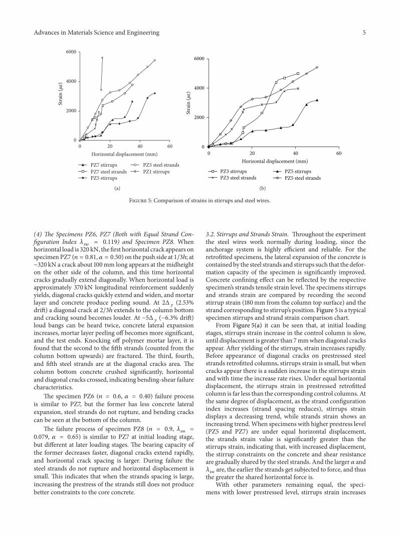
Figure 5: Comparison of strains in stirrups and steel wires.
(4) The Specimens PZ6, PZ7 (Both with Equal Strand Con-figuration Index 𝜆
𝑠𝑤= 0.119) and Specimen PZ8. When
horizontal load is 320 kN, the first horizontal crack appears onspecimen PZ7 (𝑛 = 0.81,𝛼 = 0.50) on the push side at 1/3ℎ; at−320 kN a crack about 100mm long appears at the midheighton the other side of the column, and this time horizontalcracks gradually extend diagonally. When horizontal load isapproximately 370 kN longitudinal reinforcement suddenlyyields, diagonal cracks quickly extend and widen, andmortarlayer and concrete produce peeling sound. At 2Δ
𝑦(2.53%
drift) a diagonal crack at 2/3ℎ extends to the column bottomand cracking sound becomes louder. At −5Δ
𝑦(−6.3% drift)
loud bangs can be heard twice, concrete lateral expansionincreases, mortar layer peeling off becomes more significant,and the test ends. Knocking off polymer mortar layer, it isfound that the second to the fifth strands (counted from thecolumn bottom upwards) are fractured. The third, fourth,and fifth steel strands are at the diagonal cracks area. Thecolumn bottom concrete crushed significantly, horizontaland diagonal cracks crossed, indicating bending-shear failurecharacteristics.
The specimen PZ6 (𝑛 = 0.6, 𝛼 = 0.40) failure processis similar to PZ7, but the former has less concrete lateralexpansion, steel strands do not rupture, and bending crackscan be seen at the bottom of the column.
The failure process of specimen PZ8 (𝑛 = 0.9, 𝜆sw =0.079, 𝛼 = 0.65) is similar to PZ7 at initial loading stage,but different at later loading stages. The bearing capacity ofthe former decreases faster, diagonal cracks extend rapidly,and horizontal crack spacing is larger. During failure thesteel strands do not rupture and horizontal displacement issmall. This indicates that when the strands spacing is large,increasing the prestress of the strands still does not producebetter constraints to the core concrete.
3.2. Stirrups and Strands Strain. Throughout the experimentthe steel wires work normally during loading, since theanchorage system is highly efficient and reliable. For theretrofitted specimens, the lateral expansion of the concrete iscontained by the steel strands and stirrups such that the defor-mation capacity of the specimen is significantly improved.Concrete confining effect can be reflected by the respectivespecimen’s strands tensile strain level.The specimens stirrupsand strands strain are compared by recording the secondstirrup strain (180mm from the column top surface) and thestrand corresponding to stirrup’s position. Figure 5 is a typicalspecimen stirrups and strand strain comparison chart.
From Figure 5(a) it can be seen that, at initial loadingstages, stirrups strain increase in the control column is slow,until displacement is greater than 7mmwhen diagonal cracksappear. After yielding of the stirrups, strain increases rapidly.Before appearance of diagonal cracks on prestressed steelstrands retrofitted columns, stirrups strain is small, but whencracks appear there is a sudden increase in the stirrups strainand with time the increase rate rises. Under equal horizontaldisplacement, the stirrups strain in prestressed retrofittedcolumn is far less than the corresponding control columns. Atthe same degree of displacement, as the strand configurationindex increases (strand spacing reduces), stirrups straindisplays a decreasing trend, while strands strain shows anincreasing trend.When specimens with higher prestress level(PZ5 and PZ7) are under equal horizontal displacement,the strands strain value is significantly greater than thestirrups strain, indicating that, with increased displacement,the stirrup constraints on the concrete and shear resistanceare gradually shared by the steel strands. And the larger 𝛼 and𝜆sw are, the earlier the strands get subjected to force, and thusthe greater the shared horizontal force is.
With other parameters remaining equal, the speci-mens with lower prestressed level, stirrups strain increases
6 Advances in Materials Science and Engineering
Table 2: Test results of key points in 𝑃-Δ curves.
Specimen number Load (kN) Displacement (mm) ductility Failure mode𝑃𝑦
rapidly; these specimens stirrups strain value is significantlyhigher than specimens with high prestress level, as seen inFigure 5(b). When horizontal displacement is 15.5mm, thestirrups yield in specimens PZ3 (𝛼 = 0.30) with lowerprestress level, while specimens PZ5 (𝛼 = 0.50), with higherprestress level, recorded stirrups strain only 650 𝜇𝜀, and at thesame loading cycle the stirrups strain of PZ3 is always largerthan of PZ5.
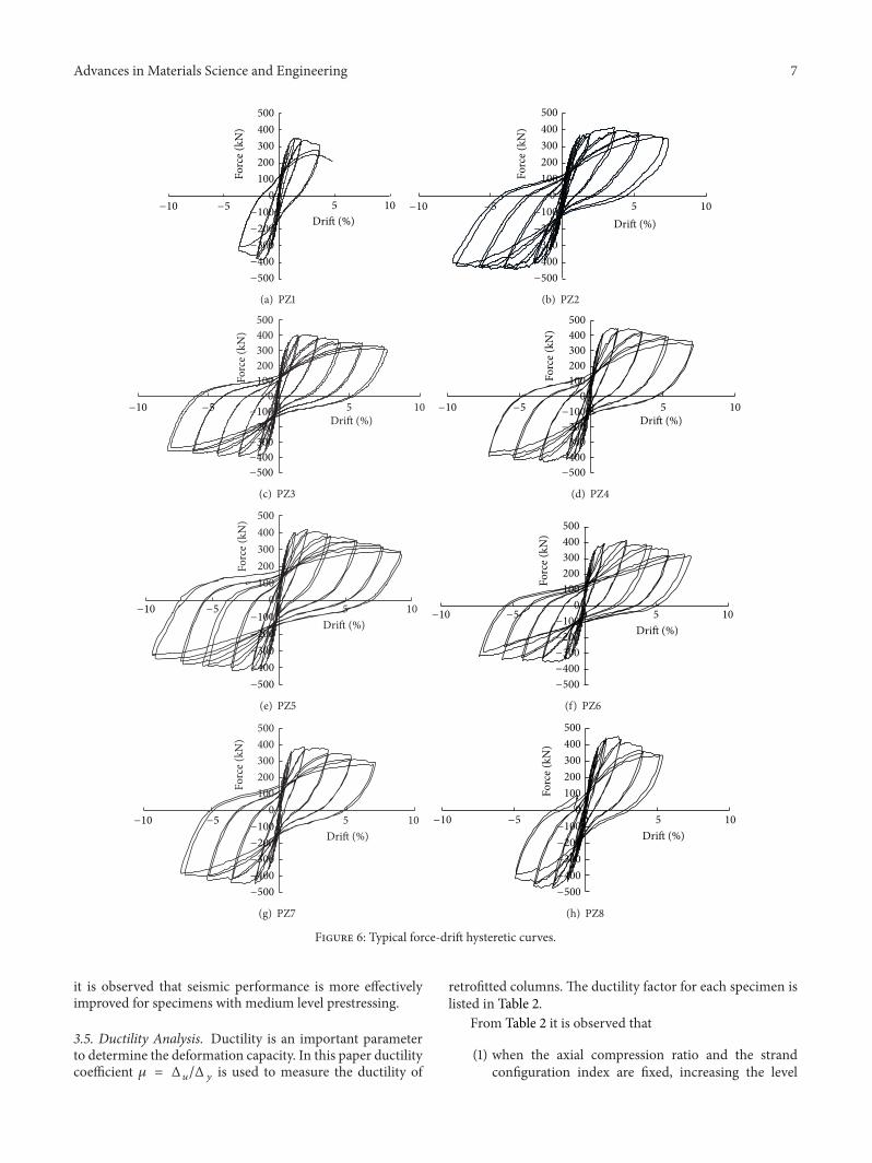
3.3. Hysteresis Curve. The measured force-drift typical hys-teresis curve is shown in Figure 6.
From Figure 6 we see the following.(1) Before yielding, the area under the force-drift hystere-
sis curves of all specimens is small, and after unload-ing the residual deformation is very small. Afteryielding, increase in loading cycles and the horizontaldisplacement leads to significantly reduced force-driftcurve slope. After unloading residual deformationgradually increases, which indicates that the stiffnessof the specimen is deteriorating.
(2) Once reaching displacement control loading stage,the unretrofitted column PZ1 undergoes shear failure,hysteresis loop at elastic-plastic phase takes an archedshape, and pinching of the curve is observed, whichdisplays shear deformation characteristics and poorseismic performance.
(3) By applying prestressed steel strand retrofitting, hys-teresis loop is generally plumped; ductility and energydissipation capacity are good.
(4) Comparing the force-drift curves of PZ1, PZ2, PZ3,and PZ4 specimens, it can be seen under the same 𝜆swand axial compression ratio, as the strand prestress-ing level is increased, the specimen hysteresis loopbecomesmore plumped and the seismic performanceis also improved.
(5) Under the same axial compression ratio and strandprestressing level (for specimens PZ5 and PZ7),increasing 𝜆sw changes the specimens failure modefrom flexural-shear failure to better ductile flexu-ral failure, and a more plumped hysteresis loop isobtained.
(6) As the axial compression ratio increases, the hystere-sis curve becomes relatively narrow. After yieldingof the specimen there is significant strength andstiffness degradation. The greater the displacement,the more the strength and stiffness degradation. Atlater loading stages, the force-drift curve becomesmore unstable.
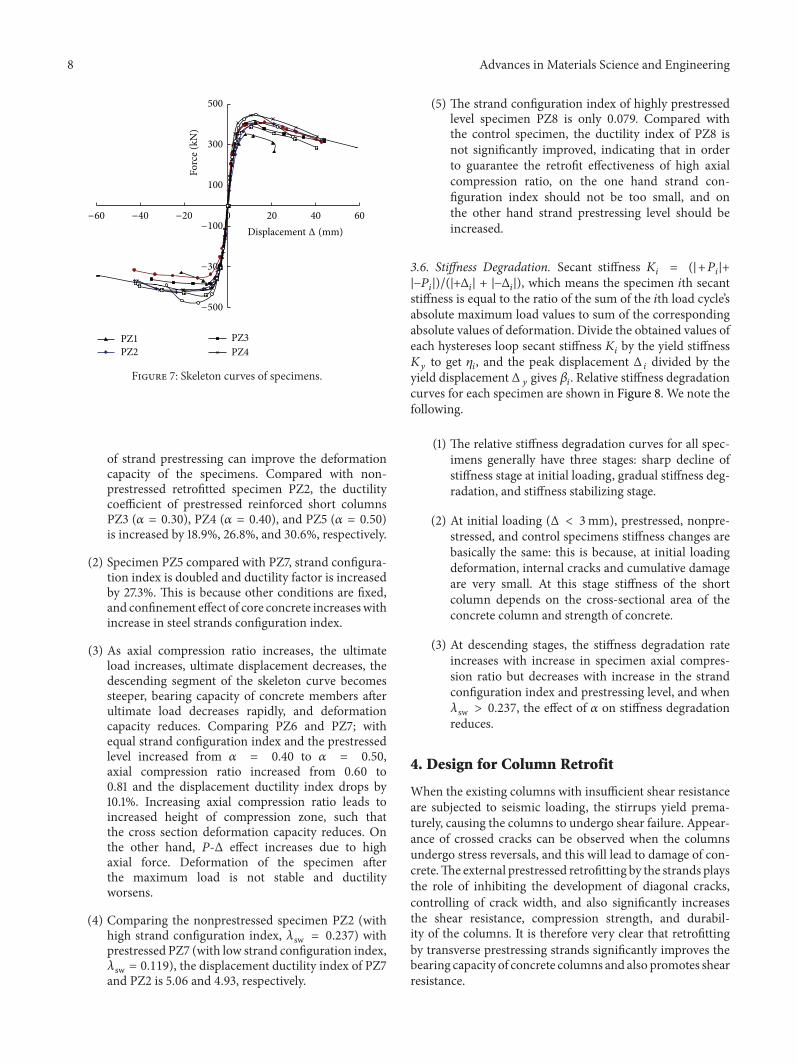
3.4. Skeleton Curve. The specimen’s 𝑃-Δ skeleton curve isshown in Figure 7.
The characteristics of each specimen (load point anddisplacement) are listed in Table 2, where 𝑃 is horizontalforce, Δ is horizontal displacement corresponding to hor-izontal loading point, and Δ
𝑦is the yield displacement
corresponding to the yield load 𝑃𝑦; 𝑃𝑦is defined as the
point, where the curve begins to bend, Δ𝑚is displacement
corresponding to the peak load𝑃𝑚andΔ
𝑢is the displacement
corresponding to the ultimate load 𝑃𝑢.
From Figure 7 it is observed that the skeleton curve ofeach specimen can be divided into elastic stage, ascendingstage, and descending stage. At elastic stage, the skeletoncurve for each specimen takes the same form, indicating thatthe effects of prestress level and confinement at elastic stageare little.
After yielding prestressing steel strands reinforced col-umns exhibit good carrying capacity; after peak load, theskeleton curve enters a horizontal stage and a gentle descend-ing stage, and seismic performance is effectively improved.Compared with the control column, nonprestressed steelstrand retrofitted column PZ2 displays improved deforma-tion, but at late loading stage skeleton curve decreases rapidlyand the descending segment is shorter. For lower strand con-figuration index specimen PZ8, though strand prestressedlevel is high, due to high axial compression ratio, descendingstage exhibits sharp decline and bending-shear failure. Whensteel strand configuration index is too low, the prestress-ing effect on improving the seismic performance of shortcolumns with high axial compression ratio is not significant.Under high axial compression ratio (𝑛 = 0.81), deformationproperties of specimens with strand configuration index0.237 (PZ2, PZ3, PZ4, and PZ5) improve with increase instrand prestressing level. Comparing PZ2, PZ3, PZ4, and PZ7,
Advances in Materials Science and Engineering 7
0100200300400500
0 5 10
Forc
e (kN
)Drift (%)
−500
−400
−300
−200
−100−10 −5
(a) PZ1
0100200300400500
0 5 10Drift (%)
Forc
e (kN
)
−500
−400
−300
−200
−100−10 −5
(b) PZ2
0100200300400500
0 5 10
Forc
e (kN
)
Drift (%)
−500
−400
−300
−200
−100−10 −5
(c) PZ3
0100200300400500
0 5 10
Forc
e (kN
)
Drift (%)
−500
−400
−300
−200
−100−10 −5
(d) PZ4
0100200300400500
0 5 10
Forc
e (kN
)
Drift (%)
−500
−400
−300
−200
−100−10 −5
(e) PZ5
0100200300400500
0 5 10
Forc
e (kN
)
Drift (%)
−500
−400
−300
−200
−100−10 −5
(f) PZ6
0100200300400500
0 5 10
Forc
e (kN
)
Drift (%)
−500
−400
−300
−200
−100−10 −5
(g) PZ7
0100200300400500
0 5 10
Forc
e (kN
)
Drift (%)
−500
−400
−300
−200
−100−10 −5
(h) PZ8
Figure 6: Typical force-drift hysteretic curves.
it is observed that seismic performance is more effectivelyimproved for specimens with medium level prestressing.
3.5. Ductility Analysis. Ductility is an important parameterto determine the deformation capacity. In this paper ductilitycoefficient 𝜇 = Δ
𝑢/Δ𝑦is used to measure the ductility of
retrofitted columns. The ductility factor for each specimen islisted in Table 2.
From Table 2 it is observed that
(1) when the axial compression ratio and the strandconfiguration index are fixed, increasing the level
8 Advances in Materials Science and Engineering
100
300
500
0 20 40 60
Forc
e (kN
)
PZ1PZ2
PZ3PZ4
−500
−300
−100−60 −40 −20
Displacement Δ (mm)
Figure 7: Skeleton curves of specimens.
of strand prestressing can improve the deformationcapacity of the specimens. Compared with non-prestressed retrofitted specimen PZ2, the ductilitycoefficient of prestressed reinforced short columnsPZ3 (𝛼 = 0.30), PZ4 (𝛼 = 0.40), and PZ5 (𝛼 = 0.50)is increased by 18.9%, 26.8%, and 30.6%, respectively.
(2) Specimen PZ5 compared with PZ7, strand configura-tion index is doubled and ductility factor is increasedby 27.3%. This is because other conditions are fixed,and confinement effect of core concrete increaseswithincrease in steel strands configuration index.
(3) As axial compression ratio increases, the ultimateload increases, ultimate displacement decreases, thedescending segment of the skeleton curve becomessteeper, bearing capacity of concrete members afterultimate load decreases rapidly, and deformationcapacity reduces. Comparing PZ6 and PZ7; withequal strand configuration index and the prestressedlevel increased from 𝛼 = 0.40 to 𝛼 = 0.50,axial compression ratio increased from 0.60 to0.81 and the displacement ductility index drops by10.1%. Increasing axial compression ratio leads toincreased height of compression zone, such thatthe cross section deformation capacity reduces. Onthe other hand, 𝑃-Δ effect increases due to highaxial force. Deformation of the specimen afterthe maximum load is not stable and ductilityworsens.
(4) Comparing the nonprestressed specimen PZ2 (withhigh strand configuration index, 𝜆sw = 0.237) withprestressed PZ7 (with low strand configuration index,𝜆sw = 0.119), the displacement ductility index of PZ7and PZ2 is 5.06 and 4.93, respectively.
(5) The strand configuration index of highly prestressedlevel specimen PZ8 is only 0.079. Compared withthe control specimen, the ductility index of PZ8 isnot significantly improved, indicating that in orderto guarantee the retrofit effectiveness of high axialcompression ratio, on the one hand strand con-figuration index should not be too small, and onthe other hand strand prestressing level should beincreased.
stiffness is equal to the ratio of the sum of the 𝑖th load cycle’sabsolute maximum load values to sum of the correspondingabsolute values of deformation. Divide the obtained values ofeach hystereses loop secant stiffness 𝐾
𝑖by the yield stiffness
𝐾𝑦to get 𝜂
𝑖, and the peak displacement Δ
𝑖divided by the
yield displacement Δ𝑦gives 𝛽
𝑖. Relative stiffness degradation
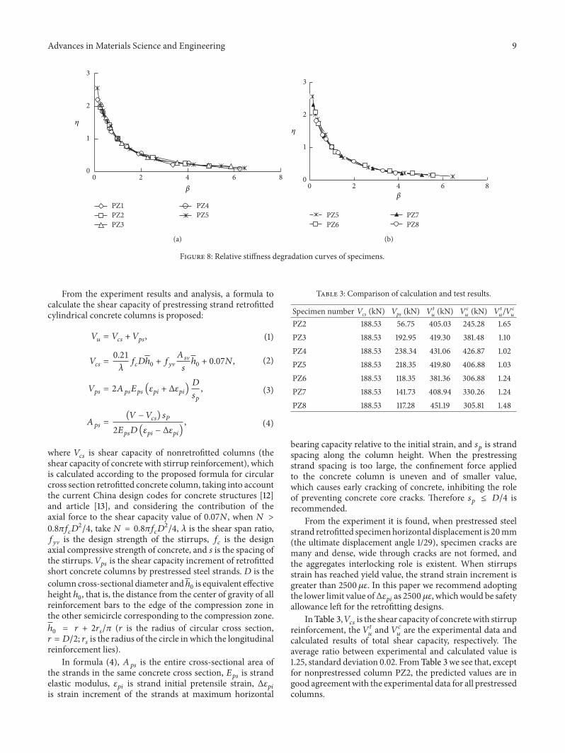
curves for each specimen are shown in Figure 8. We note thefollowing.
(1) The relative stiffness degradation curves for all spec-imens generally have three stages: sharp decline ofstiffness stage at initial loading, gradual stiffness deg-radation, and stiffness stabilizing stage.
(2) At initial loading (Δ < 3mm), prestressed, nonpre-stressed, and control specimens stiffness changes arebasically the same: this is because, at initial loadingdeformation, internal cracks and cumulative damageare very small. At this stage stiffness of the shortcolumn depends on the cross-sectional area of theconcrete column and strength of concrete.
(3) At descending stages, the stiffness degradation rateincreases with increase in specimen axial compres-sion ratio but decreases with increase in the strandconfiguration index and prestressing level, and when𝜆sw > 0.237, the effect of 𝛼 on stiffness degradationreduces.
4. Design for Column Retrofit
When the existing columns with insufficient shear resistanceare subjected to seismic loading, the stirrups yield prema-turely, causing the columns to undergo shear failure. Appear-ance of crossed cracks can be observed when the columnsundergo stress reversals, and this will lead to damage of con-crete.The external prestressed retrofitting by the strands playsthe role of inhibiting the development of diagonal cracks,controlling of crack width, and also significantly increasesthe shear resistance, compression strength, and durabil-ity of the columns. It is therefore very clear that retrofittingby transverse prestressing strands significantly improves thebearing capacity of concrete columns and also promotes shearresistance.
Advances in Materials Science and Engineering 9
0
1
2
3
0 2 4 6 8
PZ1PZ2PZ3
PZ4PZ5
𝛽
𝜂
(a)
0
1
2
3
0 2 4 6 8
PZ5PZ6
PZ7PZ8
𝛽
𝜂
(b)
Figure 8: Relative stiffness degradation curves of specimens.
From the experiment results and analysis, a formula tocalculate the shear capacity of prestressing strand retrofittedcylindrical concrete columns is proposed:
𝑉𝑢= 𝑉𝑐𝑠+ 𝑉𝑝𝑠, (1)
𝑉𝑐𝑠=0.21
𝜆𝑓𝑐𝐷ℎ0+ 𝑓𝑦V𝐴𝑠V
𝑠ℎ0+ 0.07𝑁, (2)
𝑉𝑝𝑠= 2𝐴𝑝𝑠𝐸𝑝𝑠(𝜀𝑝𝑖+ Δ𝜀𝑝𝑖)𝐷
𝑠𝑝
, (3)
𝐴𝑝𝑠=(𝑉 − 𝑉
𝑐𝑠) 𝑠𝑃
2𝐸𝑝𝑠𝐷(𝜀𝑝𝑖− Δ𝜀𝑝𝑖)
, (4)
where 𝑉𝑐𝑠is shear capacity of nonretrofitted columns (the
shear capacity of concrete with stirrup reinforcement), whichis calculated according to the proposed formula for circularcross section retrofitted concrete column, taking into accountthe current China design codes for concrete structures [12]and article [13], and considering the contribution of theaxial force to the shear capacity value of 0.07𝑁, when 𝑁 >0.8𝜋𝑓𝑐𝐷2/4, take 𝑁 = 0.8𝜋𝑓
𝑐𝐷2/4, 𝜆 is the shear span ratio,
𝑓𝑦V is the design strength of the stirrups, 𝑓
𝑐is the design
axial compressive strength of concrete, and 𝑠 is the spacing ofthe stirrups. 𝑉
𝑝𝑠is the shear capacity increment of retrofitted
short concrete columns by prestressed steel strands. 𝐷 is thecolumn cross-sectional diameter andℎ
0is equivalent effective
height ℎ0, that is, the distance from the center of gravity of all
reinforcement bars to the edge of the compression zone inthe other semicircle corresponding to the compression zone.ℎ0= 𝑟 + 2𝑟
𝑠/𝜋 (𝑟 is the radius of circular cross section,
𝑟 = 𝐷/2; 𝑟𝑠is the radius of the circle in which the longitudinal
reinforcement lies).In formula (4), 𝐴
𝑝𝑠is the entire cross-sectional area of
the strands in the same concrete cross section, 𝐸𝑝𝑠
is strandelastic modulus, 𝜀
𝑝𝑖is strand initial pretensile strain, Δ𝜀
𝑝𝑖
is strain increment of the strands at maximum horizontal
Table 3: Comparison of calculation and test results.
bearing capacity relative to the initial strain, and 𝑠𝑝is strand
spacing along the column height. When the prestressingstrand spacing is too large, the confinement force appliedto the concrete column is uneven and of smaller value,which causes early cracking of concrete, inhibiting the roleof preventing concrete core cracks. Therefore 𝑠
𝑝≤ 𝐷/4 is
recommended.From the experiment it is found, when prestressed steel
strand retrofitted specimenhorizontal displacement is 20mm(the ultimate displacement angle 1/29), specimen cracks aremany and dense, wide through cracks are not formed, andthe aggregates interlocking role is existent. When stirrupsstrain has reached yield value, the strand strain increment isgreater than 2500𝜇𝜀. In this paper we recommend adoptingthe lower limit value ofΔ𝜀
𝑝𝑖as 2500𝜇𝜀, whichwould be safety
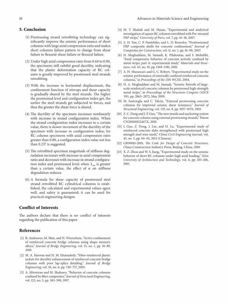
allowance left for the retrofitting designs.InTable 3,𝑉
𝑐𝑠is the shear capacity of concretewith stirrup
reinforcement, the 𝑉𝑡𝑢and 𝑉𝑐
𝑢are the experimental data and
calculated results of total shear capacity, respectively. Theaverage ratio between experimental and calculated value is1.25, standard deviation 0.02. FromTable 3 we see that, exceptfor nonprestressed column PZ2, the predicted values are ingood agreementwith the experimental data for all prestressedcolumns.
10 Advances in Materials Science and Engineering
5. Conclusion
(1) Prestressing strand retrofitting technology can sig-nificantly improve the seismic performance of shortcolumnswith large axial compression ratio andmakesshort columns failure pattern to change from shearfailure to flexural-shear failure or flexural failure.
(2) Under high axial compression ratio from 0.60 to 0.90,the specimens still exhibit good ductility, indicatingthat the plastic deformation capacity of RC col-umn is greatly improved by prestressed steel strandsretrofitting.
(3) With the increase in horizontal displacement, theconfinement function of stirrups and shear capacityis gradually shared by the steel strands. The higherthe prestressed level and configuration index get, theearlier the steel strands get subjected to forces, andthus the greater the shear force is shared.
(4) The ductility of the specimen increases nonlinearlywith increase in strand configuration index. Whenthe strand configuration index increases to a certainvalue, there is slower increment of the ductility of thespecimen with increase in configuration index; forRC column specimens with axial compression ratiogreater than 0.80, a configuration index value not lessthan 0.237 is suggested.
(5) The retrofitted specimen magnitude of stiffness deg-radation increases with increase in axial compressionratio and decreases with increase in strand configura-tion index and prestressed level; when 𝜆sw is greaterthan a certain value, the effect of 𝛼 on stiffnessdegradation reduces.
(6) A formula for shear capacity of prestressed steelstrand retrofitted RC cylindrical columns is estab-lished, the calculated and experimental values agreewell, and safety is guaranteed; it can be used forpractical engineering designs.
Conflict of Interests
The authors declare that there is no conflict of interestsregarding the publication of this paper.
References
[1] B. Andrawes, M. Shin, and N. Wierschem, “Active confinementof reinforced concrete bridge columns using shape memoryalloys,” Journal of Bridge Engineering, vol. 15, no. 1, pp. 81–89,2010.
[2] M. A. Haroun and H. M. Elsanadedy, “Fiber-reinforced plasticjackets for ductility enhancement of reinforced concrete bridgecolumns with poor lap-splice detailing,” Journal of BridgeEngineering, vol. 10, no. 6, pp. 749–757, 2005.
[3] A. Mirmiran and M. Shahawy, “Behavior of concrete columnsconfined by fiber composites,” Journal of Structural Engineering,vol. 123, no. 5, pp. 583–590, 1997.
[4] M. T. Shahab and M. Hasan, “Experimental and analyticalinvestigation of square RC columns retrofittedwith Pre-stressedFRP strips,” University of Paris, vol. 7, pp. 16–18, 2007.
[5] Z. H. Yan, C. P. Pantelides, and L. D. Reaveley, “PosttensionedFRP composite shells for concrete confinement,” Journal ofComposites for Construction, vol. 11, no. 1, pp. 81–90, 2007.
[6] H. Moghaddam, M. Samadi, K. Pilakoutas, and S. Mohebbi,“Axial compressive behavior of concrete actively confined bymetal strips; part A: experimental study,” Materials and Struc-tures, vol. 43, no. 10, pp. 1369–1381, 2010.
[7] A. H. Munawarz and G. C. Robert, “Experimental study on theseismic performance of externally confined reinforced concretecolumns,” in Proceedings of the 13th WCEE, 2004.
[8] H. A. Moghaddam and M. Samadi, “Seismic Retrofit of large-scale reinforced concrete columns by prestressed high-strengthmetal strips,” in Proceedings of the Structures Congress (ASCE’09), pp. 2863–2872, May 2009.
[9] M. Saatcioglu and C. Yalcin, “External prestressing concretecolumns for improved seismic shear resistance,” Journal ofStructural Engineering, vol. 129, no. 8, pp. 1057–1070, 2003.
[10] Z. C. Deng and J. P. Guo, “Thenew tensile and anchoring systemfor concrete column using external prestressing strands,” PatentCN201010152467.X, 2010.
[11] J. Guo, Z. Deng, J. Lin, and H. Lu, “Experimental study ofreinforced concrete slabs strengthened with prestressed highstrength steel wire mesh,” China Civil Engineering Journal, vol.45, no. 5, pp. 84–92, 2012 (Chinese).
[12] GB50010-2010, The Code for Design of Concrete Structures,China Construction Industry Press, Beijing, China, 2010.
[13] X. Z. Zhou andW. S. Jiang, “Experimental study on the seismicbehavior of short RC columns under high axial loading,” Xi’anUniversity of Architecture and Technology, vol. 6, pp. 103–106,1985.