Research ArticleTorsional Behaviour and Finite Element Analysis ofthe Hybrid Laminated Composite Shafts: Comparison ofVARTM with Vacuum Bagging Manufacturing Method
Mehmet Emin TaGdelen,1 Mehmet Halidun KeleGtemur,2 and Ercan Fevkat2
1Department of Materials Science and Engineering, Erciyes University, Melikgazi, 38039 Kayseri, Turkey2Department of Mechanical Engineering, Meliksah University, Talas, 38280 Kayseri, Turkey
Correspondence should be addressed to Mehmet Emin Tasdelen; [email protected]
Braided sleeve composite shafts are produced and their torsional behavior is investigated. The braided sleeves are slid over an Altube to create very strong and rigid tubular form shafts and they are in the form of 2/2 twill biaxial fiber fabric that has been woveninto a continuous sleeve. Carbon and glass fibers braided sleeves are used for the fabrication of the composite shafts. VARTM(vacuum assisted resin transfer molding) and Vacuum Bagging are the two different types of manufacturing methods used in thestudy. Torsional behaviors of the shafts are investigated experimentally in terms of fabrication methods and various compositematerials parameters such as fiber types, layer thickness, and ply angles. Comparing the two methods in terms of the torque forcesand strain angles, the shafts producing entirely carbon fiber show the highest torque capacities; however, considering the cost andperformance criteria, the hybrid shaftmade up of carbon and glass fibers is the optimum solution for average demanded properties.Additionally, FE (finite element) model of the shafts was created and analyzed by using ANSYS workbench environment. Resultsof finite element analysis are compared with the values of twisting angle and torque obtained by experimental tests.
1. Introduction
Composite materials are used in a wide range of industrialapplications due to their lightweight and high specific stiff-ness (𝐸/𝜌) ratio.They have been widely used for componentsof aerospace and military airplane structures in their earlierpractices. Composite materials are recently used in a lot ofcommercial applications replacing the conventionalmaterialssuch as metallic alloys and polymers and it is a fact that thecomposite technologies have had tremendous developmentcomparing with its earlier situation. New matrix materialsand various reinforcing components have led to advancedimprovement in the composite technology. At the same time,as it is expected, composite materials and its technology arehaving great challenges with this extremely high progress.
Shafts are widely used components of machines fortransferring the motion and generally they are subject to thetorsional cyclic loading in the long range duration; therefore,behaviors of torsion, damping, and corrosion resistance of
the materials are main properties to be considered. One ofthe important alternative candidate materials for shafts canbe a composite. Decrease in weight which is provided byusing composite materials is leading to reaching high specificstiffness ratio and high rotating speed due to increase innatural frequency. Additionally, shafts made up of polymermatrix composites have some additional advantages withnonmagnetic, small thermal expansion coefficient and highwear resistance.
The studies on composite shafts have nearly 30-yearhistory [1, 2]. Composite shafts have been used in variousfields such as in marine vehicles [1, 3–5], aviation [6–8],geothermal applications [9], and automotive industry [2, 10–16].
The studies done on composite shafts are focused oneffects of the mechanical properties, such as torsional behav-ior, natural bending frequency, and fatigue life, in terms ofply orientation angles, fiber types, and stacking sequences[7, 11, 14, 16, 17]. Analytical, experimental, and numerical
Hindawi Publishing CorporationAdvances in Materials Science and EngineeringVolume 2016, Article ID 9490375, 8 pageshttp://dx.doi.org/10.1155/2016/9490375
2 Advances in Materials Science and Engineering
Table 1: Density and viscosity of the resin and its hardener.
analyses have been carried out in the studies [16, 18]. Optimalparameters for shaft design and curing cycle effects of resinon torque capacity of hybrid composites shafts have beeninvestigated by various research groups [19–21].
Sevkat et al. investigate the effect of lay-up sequence onthe performance of hybrid composite shaft in torsion state,which were manufactured by filament winding technique[22, 23]. It has been shown that torsional behavior of thecomposite shaft changes by its lay-up sequence and fibertype. Tate et al. found that tensile and fatigue properties aresensitive to braid angle [17]. Mutasher had found that thestatic torque capacities of the hybrid shaft could increase viaincreasing the number of composite layers and fiber types[14]. Badie et al. investigated the effects of fiber orientationangle and stacking sequence on the torsional stiffness, fatiguelife, and some other mechanical properties of the shaft [16].They found that ply angle and stacking sequence has aconsiderable effect on the buckling torque.
In this study, the effect of fiber hybridization on torsionalbehavior in composite layer has been experimentally inves-tigated in terms of fabrication methods, which are VacuumBagging and VARTM, and different fiber types, glass andcarbon. Additionally, the solid modeling of composite shaftshas been created and stress analyses have been carried out byusing finite element method.
2. Materials and Method
Two different types of fibers have been used, carbon andE-glass fibers, for the reinforcement component and epoxyresin; Hexion L285 lamination and hardener, Hexion L287,were used for the matrix structure (Table 1). Carbon and E-glass fibers were in the form of braided sleeves and producedby Barthels-Feldhoff. The braided sleeves were worn on theouter side of aluminum tube having 16.70mm of inner diam-eter and 18.90mmof outer diameter.Hybrid composite struc-ture was obtained by changing the stacking sequence of layersand fiber type. Shafts were produced in four different con-figurations: four-layer glass/epoxy, two-layer glass/epoxy-two-layer carbon/epoxy, two-layer carbon/epoxy-two-layerglass/epoxy, and four-layer carbon/epoxy and Table 2 sum-marizes configurations of produced shaft specimens. Twoproduction methods which were Vacuum Bagging andVARTM (vacuum assisted resin transfer molding) for eachlay-up configuration were performed to obtain differenthybrid shafts. Manufactured shafts were kept in the roomtemperature for 24 hours; then all of the specimens cured at60∘C for 16 hours.
Vacuum Bagging method and VARTM (vacuum assistedresin transfer method) were applied as it is defined in theliteratures [24–26].
Table 2: Configuration of produced shaft specimens for twodifferent production methods.
Fiber type Vacuum Bagging VARTM[Carbon]
4✓ ✓
[E-glass]4
✓ ✓
[Carbon]2+ [E-glass]
2✓ ✓
[E-glass]2+ [carbon]
2✓ ✓
Figure 1: A Vacuum Bagging specimen before the bagging stage.
2.1. Production of the Shafts and Preparing the Test Specimens.The composite components, fibers and resins, were suppliedfrom the same sources for two production methods. Shaftshave been made by using the Vacuum Bagging method(Figure 1). All specimens were wrapped in a peel-ply forobtaining a smooth surface at the end stage. The preparedsample which was wrapped in a peel-ply is wrapped byvacuum blanket before the Vacuum Bagging. The vacuumblanket was used to absorb excessive resin on the compositelayers. Later, the prepared shaft was placed in a vacuum bagand then vacuuming was started.
The braided sleeves were placed on aluminum tubeswithout resin in the VARTMmethod. Later, prepared samplewas placed into the vacuum bag and vacuuming was started.While vacuum was applied from one end of the bag, resinwas fed from the other end (Figure 2). The vacuum blanketwas not used in the VARTM method since excessive resinwas aspirated by vacuum. Resin feeding ends were blindedafter samples entirely wetted by resin. Samples have been keptunder vacuum for 5 hours. Shafts were taken off from thevacuum bags, after the polymerization has been completelydone.
2.2. Torsion Test Specimens. All shafts were truncated fromtwo ends into 300mm for length alignment. Two ends of theshaft were immersed into the steel square tubes to be ableto hold the specimens/shaft onto the torsion test machine.100mm lengths of steel square tubes were adhesively gluedup to the specimens/shafts by epoxy resin (Figure 3).
2.3. Experimental Procedure. Static torsion tests were per-formed by using MTS 215 static and dynamic torsion testmachine with max. 25 kNm static torsion capacity (Figure 4).Angle controlled torsion test has been conducted. All hybridcomposite shafts were tested at the rate of 0.1666∘/s. Testswere ended with the rapid load loss. All load and angle testdata were recorded instantaneously while tests were beingperformed. A broken test specimen is shown in Figure 5.
The tests were performed under identical conditions withthree samples so that the results are reproducible. These data
Advances in Materials Science and Engineering 3
Table 3: Average fiber orientation angles on each layer for each sequence.
Figure 2: VARTM specimens while resin feeding is done byvacuum.
Figure 3: Shaft specimens with steel tube fitted to two ends.
Figure 4: A shaft specimen while torsion test is performed.
Figure 5: A damaged shaft at the end of torsion test.
Figure 6: Measuring the orientation angle of fiber.
were used for producing graphs for the sake of comparison ofresults.
Comparisons were made in terms of production meth-ods, VARTM and Vacuum Bagging, and design parameters,the fiber layer stacking order sequence and fiber types. Thefiber angle changes layer to layer depending on the outerdiameter of the shaft which is increased by composite layersbecause of using 2D braided sleeves. Therefore, the firstlayer fiber’s angle is smaller than that of last layer. Thisformation is important for finite element (FE) modeling.All fiber angles of layers were measured by the picture ofsamples taken during manufacturing. An example picture ofon-screen measuring is given in Figure 6. The average fiberangles for each specimen in terms of layer sequence are shownin Table 3.
3. Finite Element Studies
ANSYS software code version 14.5 workbench environmentwas used for creating the solid models and analyzing thetorsional behavior. And the following assumptions have beenmade:
(i) Composite laminates are shell layers.(ii) Each of the braided sleeves layers is modeled in two
shell layers in order to model ±𝜃 fiber angle.(iii) Shaft tubemade up of Al is a linear elastic orthotropic
material and it is not included into the solutionbecause of weak bonding with the composite layer.
Linear elastic orthotropic model was used for simulatingtorsional behavior of composite tubes. Nine elastic constantswere determined and implemented in FE model. The lin-ear elastic orthotropic material model was carried out formodeling the static torsion-twisting angle test since it pro-vides an acceptable assumption for highly brittle compositematerial behavior under torsional loading. FE simulations
4 Advances in Materials Science and Engineering
61
62
3363
64
3475
76
4177
78
42
Material numberLayer number
Theta
−42
−41
−34
−33
(a)
61
3862
63
4064
75
3476
77
3578
Material numberLayer number
Theta
−40
−38
−35
−34
(b)
61
62
3863
64
4065
66
4167
68
42
Material numberLayer number
Theta
−42
−41
−40
−38
(c)
61
62
3363
64
3465
66
3467
68
35
Material numberLayer number
Theta
−35
−34
−34
−33
(d)
Figure 7: Lay-up sequences and ply angles of composite shafts. (a) [C]2[G]2, (b) [G]
2[C]2, (c) [G]
4, and (d) [C]
4.
Figure 8: 3D model of FE geometry.
were carried out under torque load controlled situations.Themaximum applied load for each FE model configuration waschosen considering the level wherein the catastrophic failurehappens during the experimental tests. FE simulationmodelswere created for four different stacking sequences similarto the specimens used in experimental studies (Table 2).Each FE model includes eight shell layers for simulatingthe composite part of shafts (Figure 7). All shell layers have0.15625mm thickness. The geometry of solid model createdfor FE analysis is given in Figure 8.
Each of the solid models involves 11568 nodes and 11520elements, for the shell layer. The element type was selected asquadratic for the shell layer, and the element size was adjusted
as 1.25mm.The element typewas selected as quad/tri in ordertomodel the grip attachment. Grip sections ofmodels include12408 nodes and 3360 elements. FE studies were performedon the PC having an Intel Core i5 CPU and 6GB RAMwith the operating system Windows V. 8.0. Approximately, 5minutes was spent for performing each test.
Engineering elastic constants and Poisson’s ratios of thecomposite laminates were derived by using tensile test resultsand some analytical relations (Table 4).
In order to obtain Young’s modulus at fiber direction(𝐸1= 𝐸2), tensile tests are performed on specimens which
consist of only oriented fibers on 𝑥 and 𝑦 directions ofspecimens. The oriented fibers are gained by cutting braidedsleeves across to length and then stretched on a plain(Figure 9). Carbon/epoxy and E-glass/epoxy composite ten-sile test specimens are manufactured with VARTM methodand then tested by followingASTM standardwhich is D-3039(Figure 10).
The out-of-plane Young’s modulus (𝐸3) is computed by
using
𝐸3=
𝐸𝑚𝐸𝑓
𝑉𝑓𝐸𝑚+ (1 − 𝑉
𝑓) 𝐸𝑓
. (1)
Advances in Materials Science and Engineering 5
Table 4: Engineering elastic constants, Poisson’s ratios, and density of the carbon and E-glass composites.
Figure 9: Carbon fiber fabric, derived from braided sleeves.
Figure 10: Tensile test specimen for carbon/epoxy composite.
Here subscripts 𝑓 and 𝑚 represent fiber and matrices,respectively. 𝐸 is Young’s modulus and 𝑉 is volume fraction.
ASTM D-3518 standard test method is used for in-planeshear response of composite materials [27, 28]. By the wayof tensile test of a laminate, which consists of ±45∘ orientedfibers, 𝐸
𝑥is obtained. Then, in-plane shear modulus is
calculated from
𝐺12=
1
4/𝐸𝑥− 1/𝐸
1− 1/𝐸
2+ 2]
12
/𝐸1
. (2)
𝐺13and 𝐺
23shear moduli are obtained through
𝐺13= 𝐺23=𝐸3
2 (1 + ]13). (3)
Although a shell element was used in FE analysis, in ANSYSthe user only has the option of defining orthotropicmaterials.Therefore, by using 5 independent constants, the remainingmaterials constants were calculated.
4. Results and Discussion
It is well known that the highest stress occurs on the outsidesurface of the shaft and it decreases inwardly in a torsionalloading state for a round specimen. Therefore, it is clearthat usages of high strength fiber at the outer shells and lowstrength fiber at the inner shells will not considerably affect
Mea
n to
rque
val
ueMean twisting angleMean torque value
Twist
ing
angl
e (∘)
0
5
10
15
20
25
30
35
0
50
100
150
200
250
300
(Nm
)
[C] 2
[G] 2
(VA
RTM
)
[C] 4
(VA
RTM
)
[G] 2
[C] 2
(VA
RTM
)
[G] 4
(VA
RTM
)
[G] 4
(Vac
uum
Bag
ging
)
[G] 2
[C] 2
(Vac
uum
Bag
ging
)
[C] 4
(Vac
uum
Bag
ging
)
[C] 2
[G] 2
(Vac
uum
Bag
ging
)
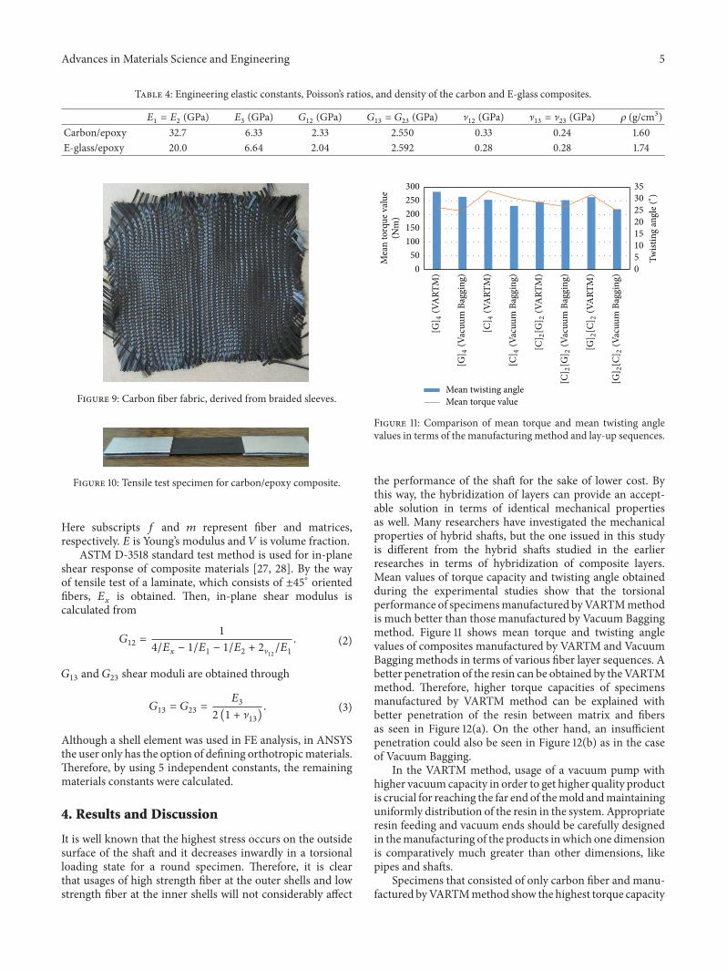
Figure 11: Comparison of mean torque and mean twisting anglevalues in terms of the manufacturing method and lay-up sequences.
the performance of the shaft for the sake of lower cost. Bythis way, the hybridization of layers can provide an accept-able solution in terms of identical mechanical propertiesas well. Many researchers have investigated the mechanicalproperties of hybrid shafts, but the one issued in this studyis different from the hybrid shafts studied in the earlierresearches in terms of hybridization of composite layers.Mean values of torque capacity and twisting angle obtainedduring the experimental studies show that the torsionalperformance of specimensmanufactured byVARTMmethodis much better than those manufactured by Vacuum Baggingmethod. Figure 11 shows mean torque and twisting anglevalues of composites manufactured by VARTM and VacuumBagging methods in terms of various fiber layer sequences. Abetter penetration of the resin can be obtained by theVARTMmethod. Therefore, higher torque capacities of specimensmanufactured by VARTM method can be explained withbetter penetration of the resin between matrix and fibersas seen in Figure 12(a). On the other hand, an insufficientpenetration could also be seen in Figure 12(b) as in the caseof Vacuum Bagging.
In the VARTM method, usage of a vacuum pump withhigher vacuum capacity in order to get higher quality productis crucial for reaching the far end of themold andmaintaininguniformly distribution of the resin in the system. Appropriateresin feeding and vacuum ends should be carefully designedin themanufacturing of the products inwhich one dimensionis comparatively much greater than other dimensions, likepipes and shafts.
Specimens that consisted of only carbon fiber and manu-factured byVARTMmethod show the highest torque capacity
6 Advances in Materials Science and Engineering
(a) (b)
Figure 12: SEM image of VARTM specimen (a) and Vacuum Bagging specimen (b).
(a) (b)
Figure 13: (a) Delaminated hybrid shafts. (b) Single-type fiber used shafts without delamination.
among the rest. The highest torque capacity can be evidentlyexplained considering higher tensile strength and elasticitymodules of carbon fiber. The highest failure twisting angleis observed on the specimen consisting of only glass fibersince its tensile strength and elasticity modules are lowerthan those of carbon fiber. Carbon fibered layers and glassfibered layers are preferred at the outer side and the inner side,respectively, because the highest stress or strain generateson the surface of shaft during the loading; consequentlythe cost of design will be cheaper with reasonable strengthloss on the entire shaft. Torsional test results of shafts withtwo glass fibered layers at the inner shell and two carbonfibered layers at the outer shell well agreed with this idea.Torsional test results of specimens designed as two glassfibered layers + two carbon fibered layers and particularlymanufactured by using VARTM method are very close tothose of entirely carbon fibered ones. Torsional test resultsof specimens with two carbon fibered layers and two glassfibered layers from the interior to the outer shell are notconsiderably different than those of entirely glass fiberedones. It can be explained that glass fibered layer located at theouter shell is exposed to the stress higher than it can resistand then damages. Therefore carbon fibered layers locatedat the inner shells cannot elongate simultaneously with
the layers made up of glass fiber due to its high elasticitymodulus, and delamination occurs between glass and carbonfibered layers during the torsional loading. This situationis viable for both hybridized samples. Even though thedelamination could be seen on hybrid shafts by investigatingdamaged shafts, the delamination has not been noticed incarbon or E-glass made shafts. In Figure 13(a), delaminationoccurring on hybrid samples can clearly be seen after thetorsion test. Thus, delamination has not occurred on samplesmade fully out of E-glass or carbon fiber; see Figure 13(b).
4.1. Results of FE Modeling. Results of finite element analysisare compared with the values of twisting angle and torqueobtained by experimental tests and they well agreed witheach other and results are given in Figures 14(a), 14(b),14(c), and 14(d). The results of specimens manufacturedby VARTM method well consisted with the results of FEsolution; therefore it can be said that a better manufacturingcan be managed by using VARTMmethod comparing to theVacuum Bagging method.
The torsional twisting angle of specimens in the exper-imental results is higher than that of FE results when theresults of experimental and FE studies are compared. It can
Advances in Materials Science and Engineering 7
FEVacuum BaggingVARTM
[C]2[G]2
0
50
100
150
200
250To
rque
(Nm
)
0 10 15 20 25 305Twisting angle (∘)
(a)
FEVacuum BaggingVARTM
0
50
100
150
200
300
250
Torq
ue (N
m)
0 10 15 20 25 35305Twisting angle (∘)
[G]2[C]2
(b)
FEVacuum BaggingVARTM
0
50
100
150
200
300
250
Torq
ue (N
m)
0 10 15 20 25 305Twisting angle (∘)
[C]4
(c)
FEVacuum BaggingVARTM
0
50
100
150
200
250
Torq
ue (N
m)
3010 15 20 255 350Twisting angle (∘)
[G]4
(d)
Figure 14: Comparison of the experimental results with FE analysis result. (a) [C]2[G]2sequence, (b) [G]
2[C]2sequence, (c) [C]
4sequence,
and (d) [G]4sequence.
be said that the slippage between grips and test specimensduring the torsional test might be a reason for this diversityand assumptions made for the FE analysis as well.
5. Conclusions
The findings obtained by this study can be summarized asfollows:
(i) Braided sleeve fabrics can be used for manufacturingof composite shafts. However, arranging the fiberorientation of plies at desired angle is not possible.
(ii) For the same lay-up sequences configuration, spec-imens which are manufactured by the VARTMmethod provide better results than those of VacuumBagging specimens, in terms ofmechanical propertiessuch as torque capacity or tensile test.
(iii) Hybridization on laminated composite structures canprovide great benefits in aspects of cost and perfor-mance criteria for the shafts which are subjected to
the torsional loading. Selection of the proper fibertype for reinforcement element is an important issue,and usages of strong fibers in the section which issubjected to high strain loads and low strong fibersfor the section which is subjected to low strains areother important issues to be considered.
(iv) As a result of the finite element analysis (FEA)of the layered composite shafts, it is noticed thatresults are promising compared to the laboratoryresults when using 2-dimensional shell elements in FEmodeling. To gain proper results between the analysisand laboratory work, one should comprehend thatthe elastic constants of composite material must bedefined precisely.
Conflict of Interests
The authors declare that there is no conflict of interestsregarding the publication of this paper.
8 Advances in Materials Science and Engineering
Acknowledgment
The authors would like to express their thanks for fundingfrom the Ministry of Science, Industry and Technology ofTurkey under Grant no. 00668.STZ.2010-2.
References
[1] A. P. Mouritz, E. Gellert, P. Burchill, and K. Challis, “Review ofadvanced composite structures for naval ships and submarines,”Composite Structures, vol. 53, no. 1, pp. 21–24, 2001.
[2] S. A. Mutasher, B. B. Sahari, A. M. S. Hamouda, and S.M. Sapuan, “Static and dynamic characteristics of a hybridaluminium/composite drive shaft,” Proceedings of the InstitutionofMechanical Engineers, Part L: Journal ofMaterials: Design andApplications, vol. 221, no. 2, pp. 63–75, 2007.
[3] V. L. Kulakov, N. A. Panfilov, and G. G. Portnov, “Evaluatingthe feasibility of using composites in ship shafting 1. Analysisof the loads and stress state of a composite shaft,” Mechanics ofComposite Materials, vol. 31, no. 6, pp. 565–572, 1996.
[4] V. L. Kulakov, N. A. Panfilov, and G. G. Pormov, “Evaluation ofpotential composite application in ship shaftlines 2.Theoreticalstudy of the crack-nucleation threshold and load-carryingcapacity of [0∘/±𝜑] laminated composites loades in shear anduniaxial tension or compression in the reinforcement plane,”Mechanics of Composite Materials, vol. 32, no. 1, pp. 39–47, 1996.
[5] J. S. Tate, A. D. Kelkar, and J. Rice, “Feasibility study of VARTMmanufacturing of carbon biaxial braided composites usingEPON 9504 epoxy resin system,” in Proceedings of the 8th JapanInternational SAMPE Symposium, pp. 1145–1148, Tokyo, Japan,November 2003.
[6] B. Spencer and J. McGee, “Designmethodology for a compositedrive shaft,” in Proceedings of the Advanced Composites Confer-ence, Dearborn, Mich, USA, December 1985.
[7] J. S. Tate, A. D. Kelkar, and V. A. Kelkar, “Failure analysis ofbiaxial braided composites under fatigue loading,” in ECF15,Stockolm 2004, 2013.
[8] E. C. Botelho, R. A. Silva, L. C. Pardini, and M. C. Rezende,“A review on the development and properties of continuousfiber/epoxy/aluminum hybrid composites for aircraft struc-tures,”Materials Research, vol. 9, no. 3, pp. 247–256, 2006.
[9] M. Tanoglu and M. Togulga, “Kompozit malzemeler ve jeoter-mal uygulamaları. VI. Ulusal Tesisat Muhendisligi Kongresi(Teskon),” in Jeoternal Enerji Dogrudan Isıtma Sistemleri; Temel-leri ve Tasarımı II. Seminer Kitabı E/2003/328-4, pp. 407–419,2003.
[10] Z. Ðorđevic, S. Maksimovic, and I. Ilic, “Dynamic analysis ofhybrid aluminum/composite shafts,” Scientific Technical Review,vol. 58, no. 2, pp. 3–7, 2008.
[11] Y.A.Khalid, S. A.Mutasher, B. B. Sahari, andA.M. S.Hamouda,“Bending fatigue behavior of hybrid aluminum/composite driveshafts,”Materials & Design, vol. 28, no. 1, pp. 329–334, 2007.
[12] D. G. Lee, H. S. Kim, J. W. Kim, and J. K. Kim, “Design andmanufacture of an automotive hybrid aluminum/compositedrive shaft,”Composite Structures, vol. 63, no. 1, pp. 87–99, 2004.
[13] D. H. Cho, D. G. Lee, and J. H. Choi, “Manufacture of one-piece automotive drive shafts with aluminum and compositematerials,” Composite Structures, vol. 38, no. 1–4, pp. 309–319,1997.
[14] S. A. Mutasher, “Prediction of the torsional strength of thehybrid aluminum/composite drive shaft,” Materials & Design,vol. 30, no. 2, pp. 215–220, 2009.
[15] M. M. Shokrieh, A. Hasani, and L. B. Lessard, “Shear bucklingof a composite drive shaft under torsion,” Composite Structures,vol. 64, no. 1, pp. 63–69, 2004.
[17] J. S. Tate, A. D. Kelkar, and J. D. Whitcomb, “Effect of braidangle on fatigue performance of biaxial braided composites,”International Journal of Fatigue, vol. 28, no. 10, pp. 1239–1247,2006.
[18] K. Xu and X. W. Xu, “Finite element analysis of mechanicalproperties of 3D five-directional braided composites,”MaterialsScience and Engineering A, vol. 487, no. 1-2, pp. 499–509, 2008.
[19] H. S. Kim, S. W. Park, H. Y. Hwang, and D. G. Lee, “Effectof the smart cure cycle on the performance of the co-curedaluminum/composite hybrid shaft,” Composite Structures, vol.75, no. 1–4, pp. 276–288, 2006.
[20] T. Rangaswamy, S. Vijayarangan, R. Chandrashekar, T.Venkatesh, and K. Anantharaman, “Optimal design andanalysis of automotive composite drive shaft,” in Proceedings ofthe International Symposium of Research Students on MaterialsScience and Engineering, pp. 1–9, December 2002.
[21] C. Ruegg and J. Habermeier, “Composite propeller shafts designand optimization,” in Advances in Composite Materials, pp.1740–1755, Pergamon Press, Paris, France, 1980.
[22] E. Sevkat, H. Tumer, M. H. Kelestemur, and S. Dogan, “Effect oftorsional strain-rate and lay-up sequences on the performanceof hybrid composite shafts,”Materials &Design, vol. 60, pp. 310–319, 2014.
[23] E. Sevkat and H. Tumer, “Residual torsional properties ofcomposite shafts subjected to impact loadings,” Materials &Design, vol. 51, pp. 956–967, 2013.
[24] J. A. Maley, An Investigation into Low-Cost Manufacturing ofCarbon Epoxy Composites and a Novel “Mouldless” TechniqueUsing the Vacuum Assisted Resin Transfer Moulding (VARTM)Method, Carleton University, Ottawa, Canada, 2008.
[25] H. Saito and I. Kimpara, “Evaluation of impact damage mech-anism of multi-axial stitched CFRP laminate,” Composites PartA: Applied Science and Manufacturing, vol. 37, no. 12, pp. 2226–2235, 2006.
[26] C. Wittman and G. D. Shook, “Hand lay-up techniques,” inHandbook of Composites, G. Lubin, Ed., pp. 321–367, Springer,New York, NY, USA, 1982.
[27] R.M. Jones,Mechanics of CompositeMaterials, Taylor&Francis,1998.
[28] E. Sevkat, B. Liaw, F. Delale, and B. B. Raju, “Drop-weightimpact of plain-woven hybrid glass-graphite/toughened epoxycomposites,” Composites Part A: Applied Science and Manufac-turing, vol. 40, no. 8, pp. 1090–1110, 2009.