52
© 2015 Empire Robotics, Inc. R20150422 Research Kit Model CV2-1 Product Manual
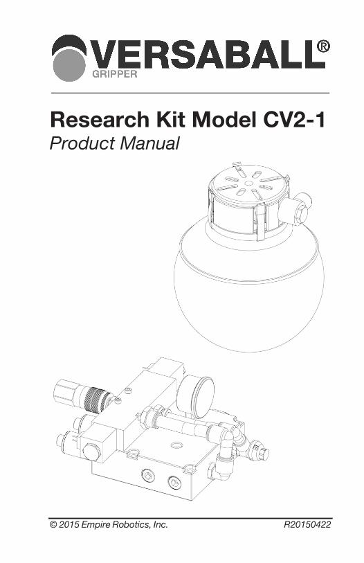
© 2015 Empire Robotics, Inc. R20150422
Research Kit Model CV2-1 Product Manual
Store this manual in a safe place for future reference.
Copyright © 2015 Empire Robotics, Inc. This document is protected by copyright. Empire Robotics, Inc. retains the rights established thereby. Reproduction of the contents, in full or in part, is only permitted within the limits of the legal provisions of copyright law. Any modifications to or abridgments of the document are prohibited without explicit written agreement from Empire Robotics, Inc.
Contact Empire Robotics, Inc. 12 Channel St., Suite 202 Boston, MA 02210 [email protected] www.empirerobotics.com
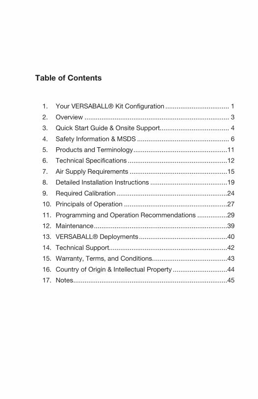
Table of Contents
1. Your VERSABALL® Kit Configuration .................................. 1 2. Overview ............................................................................. 3 3. Quick Start Guide & Onsite Support..................................... 4 4. Safety Information & MSDS ................................................. 6 5. Products and Terminology ..................................................11 6. Technical Specifications .....................................................12 7. Air Supply Requirements ....................................................15 8. Detailed Installation Instructions .........................................19 9. Required Calibration ...........................................................24 10. Principals of Operation .......................................................27 11. Programming and Operation Recommendations ................29 12. Maintenance .......................................................................39 13. VERSABALL® Deployments ...............................................40 14. Technical Support...............................................................42 15. Warranty, Terms, and Conditions. .......................................43 16. Country of Origin & Intellectual Property .............................44 17. Notes ..................................................................................45

Model CV2-1 1
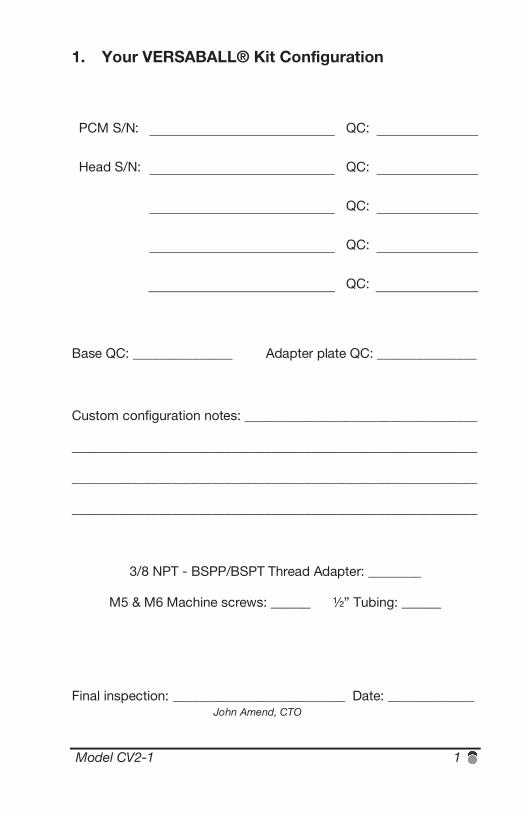
1. Your VERSABALL® Kit Configuration
PCM S/N: QC:
Head S/N: QC:
QC:
QC:
QC:
Base QC: _______________ Adapter plate QC: _______________
Custom configuration notes: ___________________________________
_____________________________________________________________
_____________________________________________________________
_____________________________________________________________
3/8 NPT - BSPP/BSPT Thread Adapter: ________
M5 & M6 Machine screws: ______ ½” Tubing: ______
Final inspection: __________________________ Date: _____________ John Amend, CTO

2 VERSABALL®
Model CV2-1 3
2. Overview Thank you for purchasing a VERSABALL® Gripper from Empire Robotics. VERSABALL® utilizes Empire’s proprietary granular jamming technology to achieve flexible and adaptive gripping through rapid hardness modulation. For video demonstrations of the capabilities of this technology visit empirerobotics.com/videos. This product manual documents the specific VERSABALL® products included in a typical Research Kit:
A. Pneumatic Control Module (PCM) B. Gripper Base C. Adapter Plate D. 6.5-inch Head E. 3.5-inch Head
Our Research Kit products are intended as an example embodiment of our granular jamming technology, suitable for conveying operating principals to the customer. Research Kits are not intended for full-time deployment. Empire sells deployment-ready grippers by tailoring product configuration and performance to a specific customer’s needs. Customizable options include: Head size, Head shape, durability, speed, air consumption, multi-gripper arrays, and more. See Section 13 for more details. To discuss deployment configurations, please contact [email protected]. This product manual contains important safety, installation, and usage information to help you get the most out of your VERSABALL® Gripper. Because your VERSABALL® represents a unique new technology, we recommend reading this manual thoroughly. If you have additional questions, if you need help installing or operating your gripper, or if your gripper is not performing as expected, please don’t hesitate to contact us at [email protected]. At Empire Robotics we continually strive to deliver the highest quality products. Your feedback is appreciated and may be provided by email at [email protected]. Thank you for choosing Empire Robotics!
4 VERSABALL®
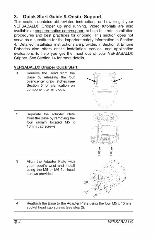
3. Quick Start Guide & Onsite Support This section contains abbreviated instructions on how to get your VERSABALL® Gripper up and running. Video tutorials are also available at empirerobotics.com/support to help illustrate installation procedures and best practices for gripping. This section does not serve as a substitute for the important safety information in Section 4. Detailed installation instructions are provided in Section 8. Empire Robotics also offers onsite installation, service, and application evaluations to help you get the most out of your VERSABALL® Gripper. See Section 14 for more details. VERSABALL® Gripper Quick Start:
1 Remove the Head from the Base by releasing the four over-center draw latches (see Section 5 for clarification on component terminology.
2 Separate the Adapter Plate from the Base by removing the four radially located M5 x 10mm cap screws.
3 Align the Adapter Plate with your robot’s wrist and install using the M5 or M6 flat head screws provided.
4 Reattach the Base to the Adapter Plate using the four M5 x 10mm socket head cap screws (see step 2).
Model CV2-1 5
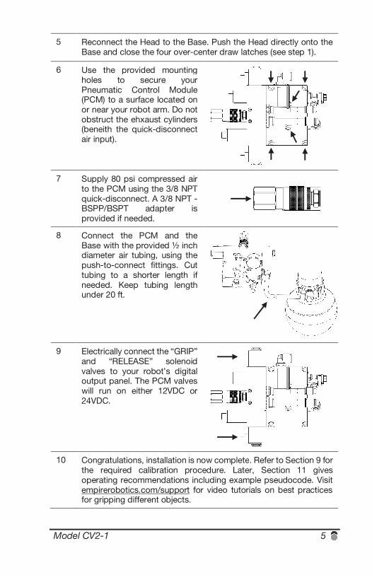
5 Reconnect the Head to the Base. Push the Head directly onto the Base and close the four over-center draw latches (see step 1).
6 Use the provided mounting holes to secure your Pneumatic Control Module (PCM) to a surface located on or near your robot arm. Do not obstruct the ehxaust cylinders (beneith the quick-disconnect air input).
7 Supply 80 psi compressed air to the PCM using the 3/8 NPT quick-disconnect. A 3/8 NPT - BSPP/BSPT adapter is provided if needed.
8 Connect the PCM and the Base with the provided ½ inch diameter air tubing, using the push-to-connect fittings. Cut tubing to a shorter length if needed. Keep tubing length under 20 ft.
9 Electrically connect the “GRIP” and “RELEASE” solenoid valves to your robot’s digital output panel. The PCM valves will run on either 12VDC or 24VDC.
10 Congratulations, installation is now complete. Refer to Section 9 for the required calibration procedure. Later, Section 11 gives operating recommendations including example pseudocode. Visit empirerobotics.com/support for video tutorials on best practices for gripping different objects.
6 VERSABALL®
4. Safety Information & MSDS Specific safety risks associated with your VERSABALL® Gripper may include but are not limited to the following. See Section 5 for clarification on component terminology. General hazards:
F. Your VERSABALL® Gripper is typically safe to use in very close proximity to human workers, providing safety advantages when in its soft compliant state. However, your VERSABALL® Gripper also contains hard metal components and the gripper Heads become very hard when vacuum-jammed. Therefore if misused, the gripper is capable of causing significant bodily harm (e.g. if it strikes a person when in use on a fast-moving robot arm). It is recommended to operate the gripper only after performing an appropriate risk assessment.
G. Your VERSABALL® Gripper is not rated for direct contact
with food products.
H. Your VERSABALL® Gripper should be treated as a piece of industrial equipment. Because of the variety of potential safety hazards described here, we do not recommend that children use this device.
Balloon membrane hazards:
I. Your VERSABALL® Gripper contains mechanisms to prevent overinflation of the balloon, however as described in Section 9, you have the ability to override the overinflate protection if needed. Exercise additional caution whenever you override the overinflation protection.
J. The outer balloon membrane of your VERSABALL®
Gripper consists of a proprietary blend of elastomeric materials and may contain some natural rubber latex. Those with latex allergies should avoid direct skin contact with the balloon membrane.
Granular material hazards:
K. Your VERSABALL® Gripper contains redundant filtering mechanisms to prevent dust particles from entering the atmosphere. In normal use, the VERSABALL® Gripper
Model CV2-1 7
emits trace amounts of dust into the atmosphere. These levels have been measured to be well below the OSHA recommended limits for respirable dust and nuisance dust, as documented in the material’s MSDS.
L. If your gripper overinflates, violently collides with a sharp
object, is used beyond its intended service life, or experiences some other unforeseen failure, the granular material contained within the gripper could be released into the environment. The grains are non-toxic and can be cleaned up with a dustpan or vacuum cleaner. During such a failure, some nuisance airborne dust may also be released, which in turn could lead to the unlikely but possible event of mechanical lung irritation (silicosis). Dampening the granular material with water spray will reduce the risk of lung irritation during cleanup.
M. If dust reaches your eyes, it could potentially cause mechanical eye irritation. If eye irritation occurs, gently rinse your eyes with water. It is advised to wear safety glasses if you are working in very close proximity to the gripper – especially if you choose to override your overinflate protection.
8 VERSABALL®
Material Safety Data Sheet (MSDS) VERSABALL® Granular Material 1. PRODUCT AND COMPANY IDENTIFICATION Product Name: VERSABALL GRANULAR MATERIAL Chemical Family: PROPRIETARY (ORGANIC) Empire Robotics, Inc. 12 Channel Street Suite 202 Boston, MA 02210 2. COMPOSITION/INFORMATION ON INGREDIENTS Natural/Organic mixture of proprietary materials Hazardous Ingredients: None 3. HAZARDS IDENTIFICATION Material is granular and light brown with no odor. Avoid creating airborne dust. Avoid ignition sources. Provide ventilation. Avoid breathing dust. Spilled material can be slippery and cause falls if walked on. Potential Health Effects: EYE: Solid or dusts may cause irritation or scratch the surface of the eye. SKIN: N/A INGESTION: N/A INHALATION: Potential respiratory tract irritation. CHRONIC HEALTH EFFECTS: None known. SARA: This material is not considered hazardous 4. FIRST AID MEASURES EYES: Flush with water. SKIN: Wash with soap and water. INGESTION: N/A INHALATION: Remove to fresh air. Call physician if irritation persists. 5. FIRE FIGHTING MEASURES Flammable Properties: Flash point is approximately 375 degrees Fahrenheit. Flammable Limits: approximately 460 degrees Fahrenheit Hazardous Combustion Products: None Extinguishing Media: Water Unusual Fire and Explosion Hazards: None. If improperly handled, stored, and/or exposed to an ignition source, this material may burn. 6. ACCIDENTAL RELEASE MEASURES Sweep up and place in appropriate disposal container. Spilled material can be a slipping hazard. Eliminate flames, sparks, and/or excessive temperatures.
Model CV2-1 9
7. HANDLING AND STORAGE HANDLING: Avoid contact with eyes. Use in a well-ventilated area. STORAGE: Store in closed, properly labeled containers in a cool, ventilated area. Keep away from heat and open flames. 8. EXPOSURE CONTROLS/PERSONAL PROTECTION ENGINEERING CONTROLS: Local exhaust – nuisance dust levels RESPIRATORY PROTECTION: N/A SKIN PROTECTION: N/A EYE PROTECTION: Safety glasses, goggles and/or a face shield OTHER PROTECTIVE EQUIPMENT: None necessary. 9. PHYSICAL AND CHEMICAL PROPERTIES BOILING POINT: N/A MELTING POINT: N/A VAPOR PRESSURE: N/A VAPOR DENSITY: N/A SOLUBILITY IN WATER: N/A EVAPORATION RATE: N/A SPECIFIC GRAVITY: (H2O=1): 1.2 – 1.35 pH: 4 to 5 @ 25 degrees C APPEARANCE: Granular or powdery, light brown. 10. STABILTY AND REACTIVITY CHEMICAL STABILITY: (Conditions to avoid) Excessive heat and/or ignition sources. INCOMPATIBILITY: None known HAZARDOUS POLYMERIZATION: Will not occur. STABILITY: Stable 11. TOXICOLOGICAL INFORMATION Toxic Substance Control Act (TSCA): VERSABALL® Granular Material is an organic product and not subject to TSCA requirements. 12. ECOLOGICAL INFORMATION Non-hazardous. Always comply with federal, state, and local environmental regulations. 13. DISPOSAL CONSIDERATIONS Dispose as solid waste in sanitary landfill according to federal, state, and local regulations. 14. TRANSPORT INFORMATION DOT: Not regulated. 15. REGULATORY INFORMATION N/A

10 VERSABALL®
16. OTHER INFORMATION The information in this MSDS was obtained from sources we believe are reliable. However, it is provided without any representation or warranty, expressed or implied, regarding accuracy or correctness. The conditions or methods of handling, storage, use and disposal of the product are beyond our control and may be beyond our knowledge. For this and other reasons, we do not assume responsibility and expressly disclaim liability for loss, damage or expense arising out of or in any way connected with the handling, storage, use, or disposal of the product.
Model CV2-1 11
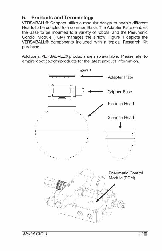
5. Products and Terminology VERSABALL® Grippers utilize a modular design to enable different Heads to be coupled to a common Base. The Adapter Plate enables the Base to be mounted to a variety of robots, and the Pneumatic Control Module (PCM) manages the airflow. Figure 1 depicts the VERSABALL® components included with a typical Research Kit purchase. Additional VERSABALL® products are also available. Please refer to empirerobotics.com/products for the latest product information.
Figure 1
Adapter Plate
Gripper Base
6.5-inch Head
3.5-inch Head
Pneumatic Control Module (PCM)
12 VERSABALL®
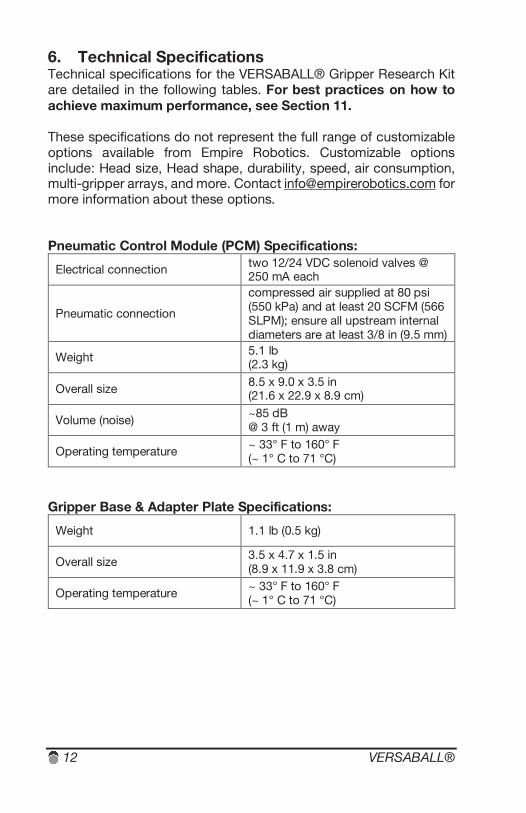
6. Technical Specifications Technical specifications for the VERSABALL® Gripper Research Kit are detailed in the following tables. For best practices on how to achieve maximum performance, see Section 11. These specifications do not represent the full range of customizable options available from Empire Robotics. Customizable options include: Head size, Head shape, durability, speed, air consumption, multi-gripper arrays, and more. Contact [email protected] for more information about these options. Pneumatic Control Module (PCM) Specifications:
Electrical connection two 12/24 VDC solenoid valves @ 250 mA each
Pneumatic connection
compressed air supplied at 80 psi (550 kPa) and at least 20 SCFM (566 SLPM); ensure all upstream internal diameters are at least 3/8 in (9.5 mm)
Weight 5.1 lb (2.3 kg)
Overall size 8.5 x 9.0 x 3.5 in (21.6 x 22.9 x 8.9 cm)
Volume (noise) ~85 dB @ 3 ft (1 m) away
Operating temperature ~ 33° F to 160° F (~ 1° C to 71 °C)
Gripper Base & Adapter Plate Specifications:
Weight 1.1 lb (0.5 kg)
Overall size 3.5 x 4.7 x 1.5 in (8.9 x 11.9 x 3.8 cm)
Operating temperature ~ 33° F to 160° F (~ 1° C to 71 °C)
Model CV2-1 13
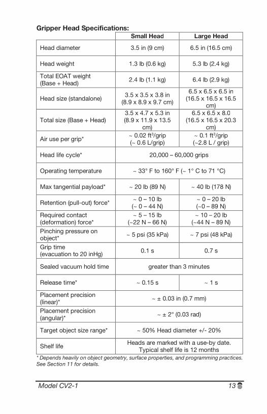
Gripper Head Specifications: Small Head Large Head
Head diameter 3.5 in (9 cm) 6.5 in (16.5 cm)
Head weight 1.3 lb (0.6 kg) 5.3 lb (2.4 kg)
Total EOAT weight (Base + Head) 2.4 lb (1.1 kg) 6.4 lb (2.9 kg)
Head size (standalone) 3.5 x 3.5 x 3.8 in (8.9 x 8.9 x 9.7 cm)
6.5 x 6.5 x 6.5 in (16.5 x 16.5 x 16.5
cm)
Total size (Base + Head) 3.5 x 4.7 x 5.3 in (8.9 x 11.9 x 13.5
cm)
6.5 x 6.5 x 8.0 (16.5 x 16.5 x 20.3
cm)
Air use per grip* ~ 0.02 ft3/grip (~ 0.6 L/grip)
~ 0.1 ft3/grip (~2.8 L / grip)
Head life cycle* 20,000 – 60,000 grips
Operating temperature ~ 33° F to 160° F (~ 1° C to 71 °C)
Max tangential payload* ~ 20 lb (89 N) ~ 40 lb (178 N)
Retention (pull-out) force* ~ 0 – 10 lb (~ 0 – 44 N)
~ 0 – 20 lb (~0 – 89 N)
Required contact (deformation) force*
~ 5 – 15 lb (~22 N – 66 N)
~ 10 – 20 lb (~44 N – 89 N)
Pinching pressure on object* ~ 5 psi (35 kPa) ~ 7 psi (48 kPa)
Grip time (evacuation to 20 inHg) 0.1 s 0.7 s
Sealed vacuum hold time greater than 3 minutes
Release time* ~ 0.15 s ~ 1 s
Placement precision (linear)* ~ ± 0.03 in (0.7 mm)
Placement precision (angular)* ~ ± 2° (0.03 rad)
Target object size range* ~ 50% Head diameter +/- 20%
Shelf life Heads are marked with a use-by date. Typical shelf life is 12 months
* Depends heavily on object geometry, surface properties, and programming practices. See Section 11 for details.

14 VERSABALL®
Model CV2-1 15
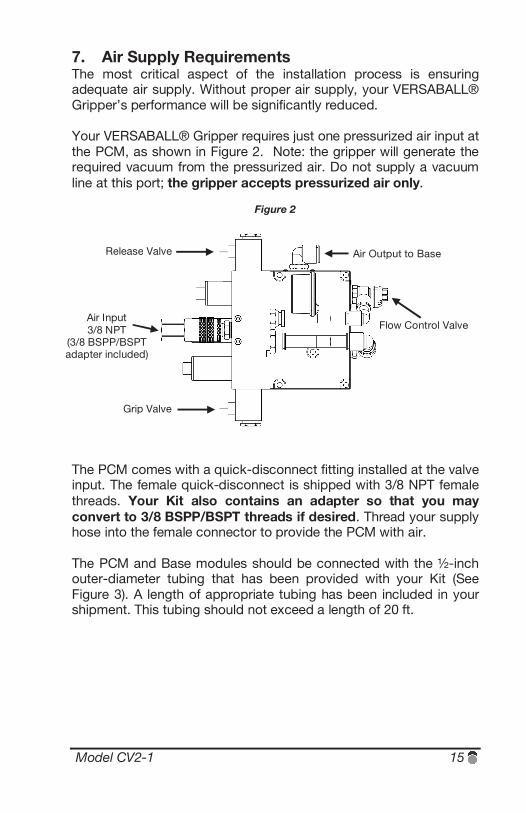
7. Air Supply Requirements The most critical aspect of the installation process is ensuring adequate air supply. Without proper air supply, your VERSABALL® Gripper’s performance will be significantly reduced. Your VERSABALL® Gripper requires just one pressurized air input at the PCM, as shown in Figure 2. Note: the gripper will generate the required vacuum from the pressurized air. Do not supply a vacuum line at this port; the gripper accepts pressurized air only.
Figure 2
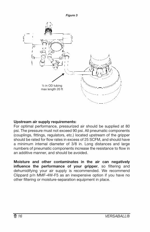
The PCM comes with a quick-disconnect fitting installed at the valve input. The female quick-disconnect is shipped with 3/8 NPT female threads. Your Kit also contains an adapter so that you may convert to 3/8 BSPP/BSPT threads if desired. Thread your supply hose into the female connector to provide the PCM with air. The PCM and Base modules should be connected with the ½-inch outer-diameter tubing that has been provided with your Kit (See Figure 3). A length of appropriate tubing has been included in your shipment. This tubing should not exceed a length of 20 ft.
Grip Valve
Release Valve
Air Input 3/8 NPT
(3/8 BSPP/BSPT adapter included)
Flow Control Valve
Air Output to Base
16 VERSABALL®
Figure 3
Upstream air supply requirements: For optimal performance, pressurized air should be supplied at 80 psi. The pressure must not exceed 90 psi. All pneumatic components (couplings, fittings, regulators, etc.) located upstream of the gripper should be rated for flow rates in excess of 25 SCFM, and should have a minimum internal diameter of 3/8 in. Long distances and large numbers of pneumatic components increase the resistance to flow in an additive manner, and should be avoided. Moisture and other contaminates in the air can negatively influence the performance of your gripper, so filtering and dehumidifying your air supply is recommended. We recommend Clippard p/n MMF-4W-F5 as an inexpensive option if you have no other filtering or moisture-separation equipment in place.
½ in OD tubing max length 20 ft
Model CV2-1 17
Testing your air supply: Test your air supply to ensure that proper pressure and flow rate are available for the gripper. Simply checking the rating on your compressor is insufficient due to restrictions, distance, and other losses as mentioned previously. Utilizing a pressure gauge and flow meter is recommended. You can also directly confirm the adequacy of your air supply testing with your VERSABALL® Gripper. See the calibration procedure in Section 9 for more information.
At the PCM input, your air supply should be capable of providing 80 psi with a flow rate of at least 20 SCFM. Measure these when the hose is disconnected from the gripper. Most shop air supplies will easily meet these requirements at the nearest pipe. Supplying your gripper with adequate airflow is simply a matter of ensuring that appropriate fittings and tubing are used between the pipe and the PCM. If it is not possible for you to provide adequate air supply, contact [email protected] to discuss possible options for reconfiguring the gripper.

18 VERSABALL®
Model CV2-1 19
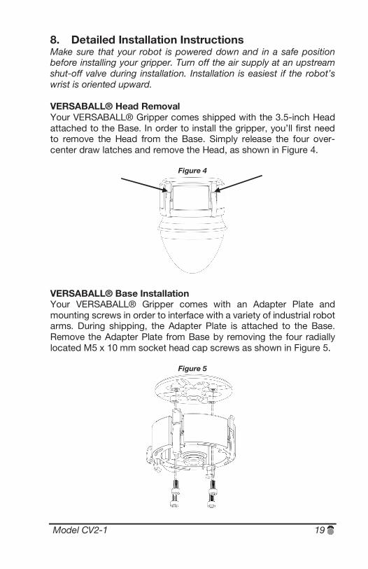
8. Detailed Installation Instructions Make sure that your robot is powered down and in a safe position before installing your gripper. Turn off the air supply at an upstream shut-off valve during installation. Installation is easiest if the robot’s wrist is oriented upward. VERSABALL® Head Removal Your VERSABALL® Gripper comes shipped with the 3.5-inch Head attached to the Base. In order to install the gripper, you’ll first need to remove the Head from the Base. Simply release the four over-center draw latches and remove the Head, as shown in Figure 4.
Figure 4
VERSABALL® Base Installation Your VERSABALL® Gripper comes with an Adapter Plate and mounting screws in order to interface with a variety of industrial robot arms. During shipping, the Adapter Plate is attached to the Base. Remove the Adapter Plate from Base by removing the four radially located M5 x 10 mm socket head cap screws as shown in Figure 5.
Figure 5
20 VERSABALL®
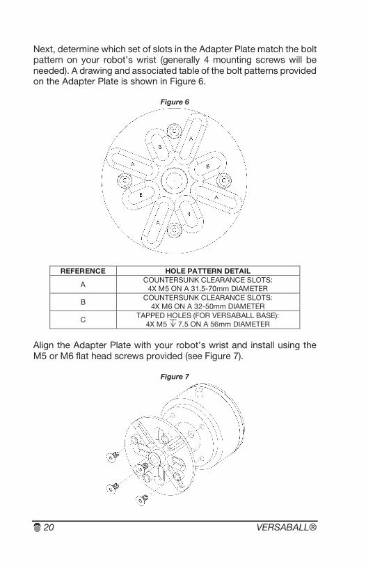
Next, determine which set of slots in the Adapter Plate match the bolt pattern on your robot’s wrist (generally 4 mounting screws will be needed). A drawing and associated table of the bolt patterns provided on the Adapter Plate is shown in Figure 6.
Figure 6
REFERENCE HOLE PATTERN DETAIL
A COUNTERSUNK CLEARANCE SLOTS:
4X M5 ON A 31.5-70mm DIAMETER
B COUNTERSUNK CLEARANCE SLOTS:
4X M6 ON A 32-50mm DIAMETER
C TAPPED HOLES (FOR VERSABALL BASE): 4X M5 7.5 ON A 56mm DIAMETER
Align the Adapter Plate with your robot’s wrist and install using the M5 or M6 flat head screws provided (see Figure 7).
Figure 7
Model CV2-1 21
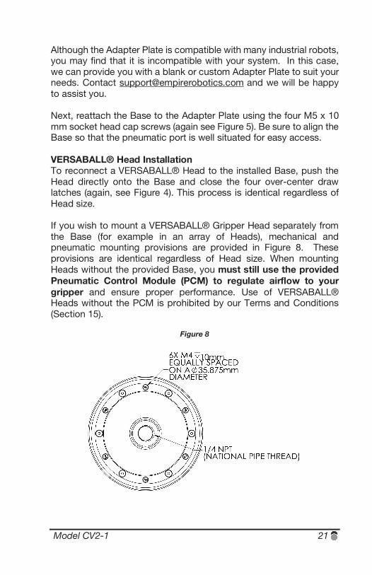
Although the Adapter Plate is compatible with many industrial robots, you may find that it is incompatible with your system. In this case, we can provide you with a blank or custom Adapter Plate to suit your needs. Contact [email protected] and we will be happy to assist you. Next, reattach the Base to the Adapter Plate using the four M5 x 10 mm socket head cap screws (again see Figure 5). Be sure to align the Base so that the pneumatic port is well situated for easy access. VERSABALL® Head Installation To reconnect a VERSABALL® Head to the installed Base, push the Head directly onto the Base and close the four over-center draw latches (again, see Figure 4). This process is identical regardless of Head size. If you wish to mount a VERSABALL® Gripper Head separately from the Base (for example in an array of Heads), mechanical and pneumatic mounting provisions are provided in Figure 8. These provisions are identical regardless of Head size. When mounting Heads without the provided Base, you must still use the provided Pneumatic Control Module (PCM) to regulate airflow to your gripper and ensure proper performance. Use of VERSABALL® Heads without the PCM is prohibited by our Terms and Conditions (Section 15).
Figure 8
22 VERSABALL®
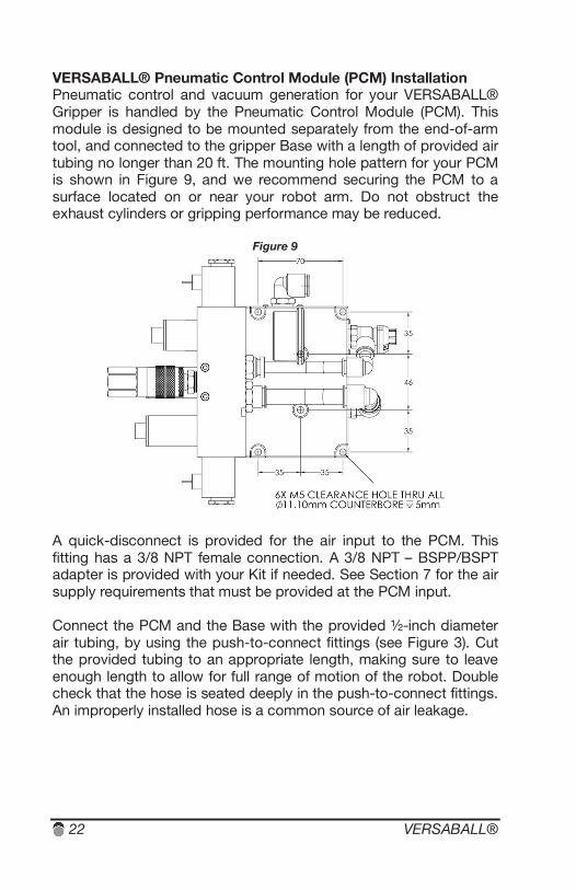
VERSABALL® Pneumatic Control Module (PCM) Installation Pneumatic control and vacuum generation for your VERSABALL® Gripper is handled by the Pneumatic Control Module (PCM). This module is designed to be mounted separately from the end-of-arm tool, and connected to the gripper Base with a length of provided air tubing no longer than 20 ft. The mounting hole pattern for your PCM is shown in Figure 9, and we recommend securing the PCM to a surface located on or near your robot arm. Do not obstruct the exhaust cylinders or gripping performance may be reduced.
Figure 9
A quick-disconnect is provided for the air input to the PCM. This fitting has a 3/8 NPT female connection. A 3/8 NPT – BSPP/BSPT adapter is provided with your Kit if needed. See Section 7 for the air supply requirements that must be provided at the PCM input. Connect the PCM and the Base with the provided ½-inch diameter air tubing, by using the push-to-connect fittings (see Figure 3). Cut the provided tubing to an appropriate length, making sure to leave enough length to allow for full range of motion of the robot. Double check that the hose is seated deeply in the push-to-connect fittings. An improperly installed hose is a common source of air leakage.

Model CV2-1 23
The solenoid valves on the PCM are labeled “GRIP” and “RELEASE” (see Figure 2). Connect the wires from each valve to your robot’s digital output panel. The PCM valves will run on either 12VDC or 24VDC at 250 mA. Make a note indicating which output each valve is connected to. A space for notes is provided in Section 17 of this manual.
24 VERSABALL®
9. Required Calibration Your VERSABALL® Gripper comes with a diagnostic vacuum gauge installed on the PCM. We recommend the following procedure to confirm your gripper’s performance immediately following installation. Use the large 6.5-inch Head for this test. 1. Carefully turn on your air supply to the PCM and listen for air leaks. 2. The flow-control valve (see Figure 2) installed on the PCM is shipped fully closed. Confirm that the valve is closed by turning clockwise. The number “0” should be visible on the dial. 3. Find the blue push buttons located on the PCM’s solenoid valve pack (located near the “GRIP” and “RELEASE” labels). These buttons enable manual operation of the valves by bypassing the electrical connection. 4. Press and hold the blue button for the valve labeled “RELEASE”. No air should flow because the flow-control valve is fully closed. With the blue button depressed, unlock the flow-control valve by pulling outward on the knob, then slowly turn counter-clockwise so that air can begin flowing into the Base/Head. Mechanisms within the PCM will limit the expansion of the Head and prevent overinflation. Continue opening the flow-control valve until the Head reaches a steady-state enlargement of about 15%. Typically this will take 5 to 7 full rotations of the valve screw. You can squeeze the Head during this process and it should be very soft. Press inward on the flow-control knob to lock it in position. Release the blue push button. 5. While watching the included vacuum gauge installed on the PCM, press and hold the blue button for the valve labeled “GRIP” for about 2 seconds. After you release the blue button, the vacuum gauge needle should hold steady in the green section of the dial (higher than 20 inHg). If the gauge does not reach the green section, there is most likely an upstream restriction in your air supply. If the gauge needle drops quickly back to zero instead of holding steady, the hose between the PCM and the Base has most likely been connected improperly.
Model CV2-1 25
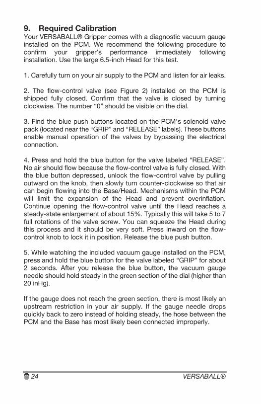
6. Switch back and forth between opening the GRIP and RELEASE valves several times to make sure performance similar to Figure 10 is achieved. Detailed measurements are not necessary. Simply confirming that the gripper exceeds 20 inHg vacuum in under 1 second is sufficient.
Figure 10
7. Adjusting the flow-control valve on the release port will require some iterative tuning because a tradeoff exists between inflation speed (object release/ejection time) and overinflation protection. You can override your overinflate protection to achieve the fastest ejection speeds when you open the flow control valve beyond about 7 turns. This is a fine way to use your gripper, but comes with obvious additional risk. See Section 11 for additional operation recommendations. If you are achieving performance similar to Figure 10 with your gripper, then the calibration is complete and the gripper has been installed successfully. If you are unable to achieve performance similar to Figure 10, contact [email protected] and we will be happy to assist you.

26 VERSABALL®
Model CV2-1 27
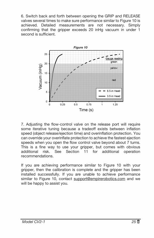
10. Principals of Operation VERSABALL® Grippers utilize a technology known as granular jamming to grip and release objects through rapid hardness modulation as shown in Figure 11. You can see this same effect if you buy vacuum-packed coffee at the grocery store – hard as a brick until you release the seal, whereupon the particles will flow more like a fluid. It is useful to keep this concept in mind when you are working with your gripper (vacuum-pack the gripper so that it will become rigid and grip onto an object, inflate the gripper to release the object and then again to soften for contact with the next object).
Figure 11
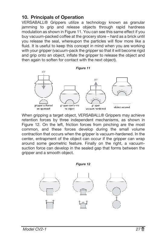
When gripping a target object, VERSABALL® Grippers may achieve retention forces by three independent mechanisms, as shown in Figure 12. On the left, friction forces from pinching are the most common, and these forces develop during the small volume contraction that occurs when the gripper is vacuum-hardened. In the center, entrapment of the object can occur if the gripper can wrap around some geometric feature. Finally on the right, a vacuum-suction force can develop in the sealed gap that forms between the gripper and a smooth object.
Figure 12

28 VERSABALL®
Model CV2-1 29
11. Programming and Operation Recommendations The following guidelines are meant to help you maximize the performance of your VERSABALL® Gripper. These guidelines can be applied toward many types of target objects, though gripping performance is highly dependent on the specific characteristics of each target object. These characteristics primarily include: size, shape, weight, hardness, and surface texture. In general, the performance of your VERSABALL® Gripper will correlate with how well the gripper can conform to the target object. The gripper’s versatility does allow it to operate well outside these optimum guidelines, however the farther from optimum any operation is, the less predictable the performance will be. Be careful not to sacrifice optimal performance by forgoing careful programming. It is worthwhile to take the time to program your gripping routine a bit more carefully in order to get the best results from your gripper. When programming you should either always use a “pulse” command to activate your gripper’s control valves, or set interrupts so that both valves will default to off whenever the robot encounters an emergency stop signal (or both). A pulse command will normally return even in the event of an emergency-stop (as opposed to a “wait” command, which will typically hang in the event of an emergency stop). Using pulse commands should greatly reduce the risk of overinflating your gripper. Nevertheless, we highly recommend that you do not open the positive pressure flow-control valve far enough to override your overinflation protection until programming is mostly complete (or preferably never). The risk of overinflating your gripper is highest during programming. In the event that you do make a programming mistake and begin overinflating the Head, a quick way to rescue it is to first e-stop your robot, and then quickly remove the air supply from the PCM using the quick-disconnect. A step-by-step guide through the gripping sequence follows next. Example pseudocode is provided at the end of this section.
30 VERSABALL®
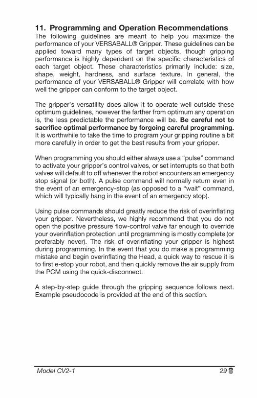
Approaching the target object: If possible, the target object should be presented on a flat rigid surface. VERSABALL® Grippers can reliably grip objects of varying size, however the optimal width of the target object (or the feature on the target object that the gripper interfaces with) that results in the highest payload capacity is approximately one half of the diameter of the gripper, as shown in Figure 13.
Figure 13
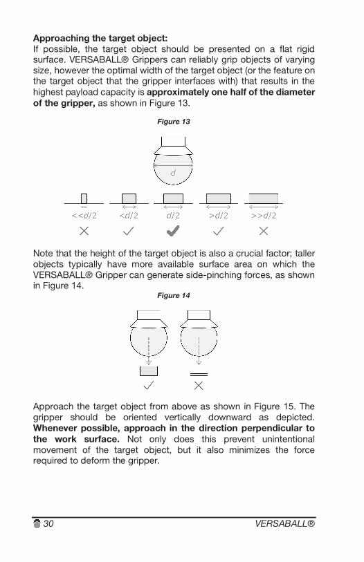
Note that the height of the target object is also a crucial factor; taller objects typically have more available surface area on which the VERSABALL® Gripper can generate side-pinching forces, as shown in Figure 14.
Figure 14
Approach the target object from above as shown in Figure 15. The gripper should be oriented vertically downward as depicted. Whenever possible, approach in the direction perpendicular to the work surface. Not only does this prevent unintentional movement of the target object, but it also minimizes the force required to deform the gripper.
Model CV2-1 31
Figure 15
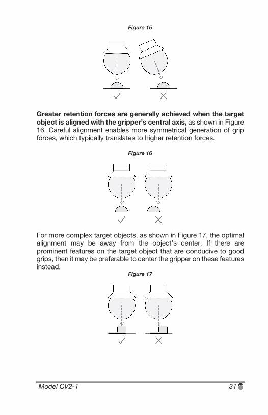
Greater retention forces are generally achieved when the target object is aligned with the gripper’s central axis, as shown in Figure 16. Careful alignment enables more symmetrical generation of grip forces, which typically translates to higher retention forces.
Figure 16
For more complex target objects, as shown in Figure 17, the optimal alignment may be away from the object’s center. If there are prominent features on the target object that are conducive to good grips, then it may be preferable to center the gripper on these features instead.
Figure 17
32 VERSABALL®
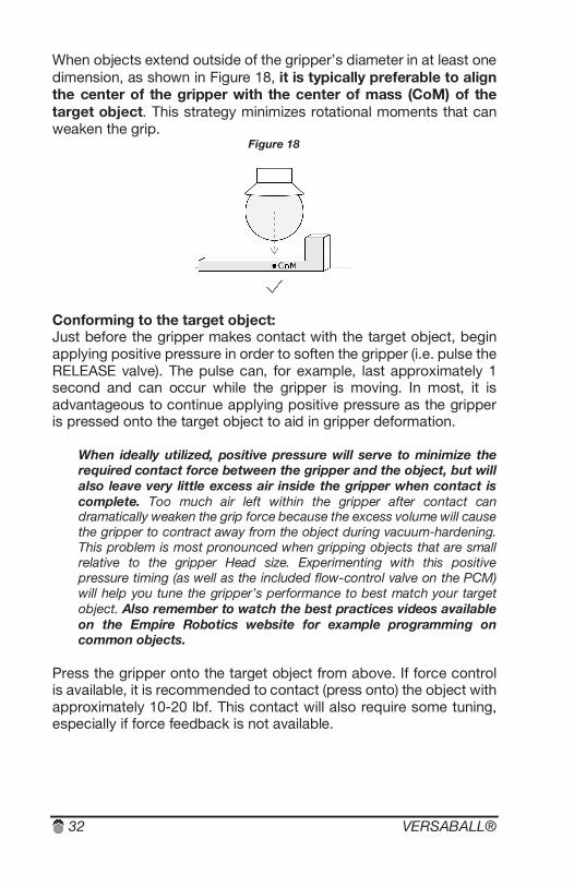
When objects extend outside of the gripper’s diameter in at least one dimension, as shown in Figure 18, it is typically preferable to align the center of the gripper with the center of mass (CoM) of the target object. This strategy minimizes rotational moments that can weaken the grip.
Figure 18
Conforming to the target object: Just before the gripper makes contact with the target object, begin applying positive pressure in order to soften the gripper (i.e. pulse the RELEASE valve). The pulse can, for example, last approximately 1 second and can occur while the gripper is moving. In most, it is advantageous to continue applying positive pressure as the gripper is pressed onto the target object to aid in gripper deformation.
When ideally utilized, positive pressure will serve to minimize the required contact force between the gripper and the object, but will also leave very little excess air inside the gripper when contact is complete. Too much air left within the gripper after contact can dramatically weaken the grip force because the excess volume will cause the gripper to contract away from the object during vacuum-hardening. This problem is most pronounced when gripping objects that are small relative to the gripper Head size. Experimenting with this positive pressure timing (as well as the included flow-control valve on the PCM) will help you tune the gripper’s performance to best match your target object. Also remember to watch the best practices videos available on the Empire Robotics website for example programming on common objects.
Press the gripper onto the target object from above. If force control is available, it is recommended to contact (press onto) the object with approximately 10-20 lbf. This contact will also require some tuning, especially if force feedback is not available.
Model CV2-1 33
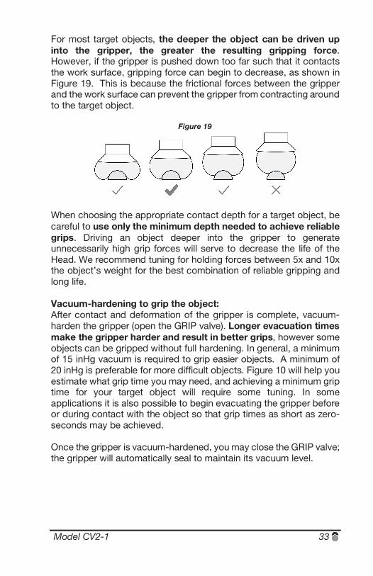
For most target objects, the deeper the object can be driven up into the gripper, the greater the resulting gripping force. However, if the gripper is pushed down too far such that it contacts the work surface, gripping force can begin to decrease, as shown in Figure 19. This is because the frictional forces between the gripper and the work surface can prevent the gripper from contracting around to the target object.
Figure 19
When choosing the appropriate contact depth for a target object, be careful to use only the minimum depth needed to achieve reliable grips. Driving an object deeper into the gripper to generate unnecessarily high grip forces will serve to decrease the life of the Head. We recommend tuning for holding forces between 5x and 10x the object’s weight for the best combination of reliable gripping and long life. Vacuum-hardening to grip the object: After contact and deformation of the gripper is complete, vacuum-harden the gripper (open the GRIP valve). Longer evacuation times make the gripper harder and result in better grips, however some objects can be gripped without full hardening. In general, a minimum of 15 inHg vacuum is required to grip easier objects. A minimum of 20 inHg is preferable for more difficult objects. Figure 10 will help you estimate what grip time you may need, and achieving a minimum grip time for your target object will require some tuning. In some applications it is also possible to begin evacuating the gripper before or during contact with the object so that grip times as short as zero-seconds may be achieved. Once the gripper is vacuum-hardened, you may close the GRIP valve; the gripper will automatically seal to maintain its vacuum level.
34 VERSABALL®
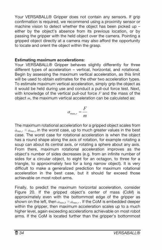
Your VERSABALL® Gripper does not contain any sensors. If grip confirmation is required, we recommend using a proximity sensor or machine vision to detect whether the object has been picked up – either by the object’s absence from its previous location, or by passing the gripper with the held object over the camera. Pointing a gripped object directly at a camera may also afford the opportunity to locate and orient the object within the grasp. Estimating maximum accelerations: Your VERSABALL® Gripper behaves slightly differently for three different types of acceleration – vertical, horizontal, and rotational. Begin by assessing the maximum vertical acceleration, as this limit will be used to obtain estimates for the other two acceleration types. To estimate maximum vertical acceleration, simply grip the object as it would be held during use and conduct a pull-out force test. Next, with knowledge of the vertical pull-out force F and the mass of the object m, the maximum vertical acceleration can be calculated as:
mFa v max,
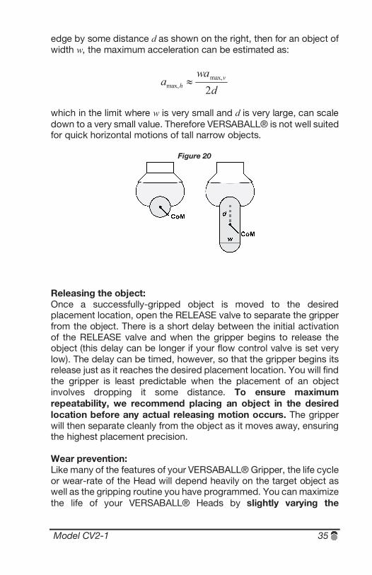
The maximum rotational acceleration for a gripped object scales from amax,r ≈ amax,v in the worst case, up to much greater values in the best case. The worst case for rotational acceleration is when the object has a round shape along the axis of rotation, for example rotating a soup can about its central axis, or rotating a sphere about any axis. From there, maximum rotational acceleration improves as the object’s number of sides decreases (e.g. from an infinite number of sides for a circular object, to eight for an octagon, to three for a triangle, to approximately two for a long narrow object). It is very difficult to make a generalized prediction for maximum rotational acceleration in the best case, but it should far exceed those achievable on most robot arms. Finally, to predict the maximum horizontal acceleration, consider Figure 20. If the gripped object’s center of mass (CoM) is approximately even with the bottommost edge of the gripper as shown on the left, then amax,h ≈ amax,v . If the CoM is embedded deeper within the gripper, then maximum acceleration scales up to a much higher level, again exceeding accelerations achievable on most robot arms. If the CoM is located further than the gripper’s bottommost
Model CV2-1 35
edge by some distance d as shown on the right, then for an object of width w, the maximum acceleration can be estimated as:
dwa
a vh 2
max,max,
which in the limit where w is very small and d is very large, can scale down to a very small value. Therefore VERSABALL® is not well suited for quick horizontal motions of tall narrow objects.
Figure 20
Releasing the object: Once a successfully-gripped object is moved to the desired placement location, open the RELEASE valve to separate the gripper from the object. There is a short delay between the initial activation of the RELEASE valve and when the gripper begins to release the object (this delay can be longer if your flow control valve is set very low). The delay can be timed, however, so that the gripper begins its release just as it reaches the desired placement location. You will find the gripper is least predictable when the placement of an object involves dropping it some distance. To ensure maximum repeatability, we recommend placing an object in the desired location before any actual releasing motion occurs. The gripper will then separate cleanly from the object as it moves away, ensuring the highest placement precision. Wear prevention: Like many of the features of your VERSABALL® Gripper, the life cycle or wear-rate of the Head will depend heavily on the target object as well as the gripping routine you have programmed. You can maximize the life of your VERSABALL® Heads by slightly varying the
36 VERSABALL®
gripper’s location and/or orientation as it contacts an object. Gripping objects in exactly the same location and orientation every time will adversely affect gripper Head life. For example, let’s say that you are programming a routine to grip a small steel cube. If you use just one pick position/orientation, where the edges of the cube contact the gripper membrane in the same exact spot on each grip, then you will dramatically decrease the life of the Head. If however you cycle through five different orientations of the gripper (which is straightforward because the gripper is rotationally symmetric), where each orientation still aligns the cube at the center of the gripper but rotated 72° apart, you should then achieve lifetimes in the range listed in Section 6. If your object is rotationally symmetric (e.g. like a soup can), you’ll want to use slight variations in the gripper’s pick location (e.g. 2-3 mm difference) instead of rotational variations. In addition, as mentioned previously, when choosing the appropriate contact depth for a target object, be careful to use only the minimum depth needed to achieve reliable grips. Driving an object deeper into the gripper to generate unnecessarily high grip forces will also serve to decrease the life of the Head.
Model CV2-1 37
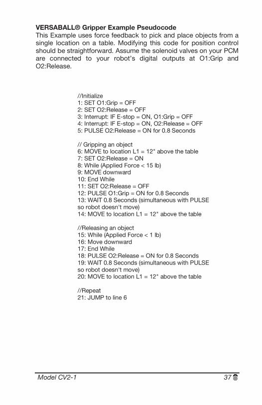
VERSABALL® Gripper Example Pseudocode This Example uses force feedback to pick and place objects from a single location on a table. Modifying this code for position control should be straightforward. Assume the solenoid valves on your PCM are connected to your robot’s digital outputs at O1:Grip and O2:Release.
//Initialize 1: SET O1:Grip = OFF 2: SET O2:Release = OFF 3: Interrupt: IF E-stop = ON, O1:Grip = OFF 4: Interrupt: IF E-stop = ON, O2:Release = OFF 5: PULSE O2:Release = ON for 0.8 Seconds // Gripping an object 6: MOVE to location L1 = 12" above the table 7: SET O2:Release = ON 8: While (Applied Force < 15 lb) 9: MOVE downward 10: End While 11: SET O2:Release = OFF 12: PULSE O1:Grip = ON for 0.8 Seconds 13: WAIT 0.8 Seconds (simultaneous with PULSE so robot doesn't move) 14: MOVE to location L1 = 12" above the table //Releasing an object 15: While (Applied Force < 1 lb) 16: Move downward 17: End While 18: PULSE O2:Release = ON for 0.8 Seconds 19: WAIT 0.8 Seconds (simultaneous with PULSE so robot doesn't move) 20: MOVE to location L1 = 12" above the table //Repeat 21: JUMP to line 6

38 VERSABALL®
Model CV2-1 39
12. Maintenance The primary item of regular maintenance that your VERSABALL® Gripper requires is the replacement of worn Heads. Without sensors, the VERSABALL® cannot alert the operator when Head replacement is required. Instead, the operator should keep an incrementing count of the number of grips in their gripping program, and thereby ensure each Head does not exceed the life cycle values reported in Section 6. The maximum number of grips will depend on the specific use-case and objects being gripped, so regular inspections of the gripper should be conducted in any new use-case. In routine use, occasional and cursory inspections by an operator are recommend. During this inspection, the operator should check for signs of wear or damage on the gripper and that it is still functioning properly. Take note of the readings on the included diagnostic vacuum gauge. Unexpected low vacuum levels should be investigated more thoroughly. Especially if the gripper is operating in a dusty environment, an occasional wipe-down with a damp cloth is also recommend.
40 VERSABALL®
13. VERSABALL® Deployments Our Research Kit products are intended as an example embodiment of our granular jamming technology, suitable for conveying operating principals to the customer. Research Kits are not intended for full-time deployment. Empire sells deployment-ready grippers by tailoring product configuration and performance to a specific customer’s needs. Customizable options include: Head size, Head shape, durability, speed, air consumption, and multi-gripper arrays. We work closely with customers before shipping grippers for full-time deployments in order to guarantee success. This includes lab testing on customer parts, optimization of the gripper Heads to maximize system performance, and on-site installation by our staff.
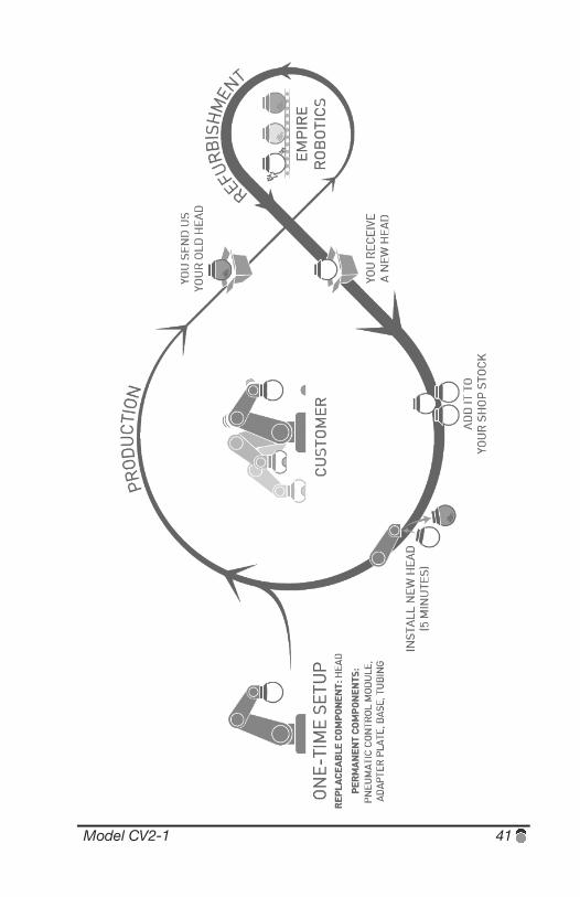
In full-time deployments, gripper Heads eventually wear out and require replacement. Head changes take less than 5 minutes, and Empire provides customers with a recurring supply of refurbished Heads to minimize cost and ensure seamless system operation. See the diagram on the next page for an illustration of the ongoing Head replacement process.
To request additional information on deployment configurations, please contact [email protected].
Model CV2-1 41
42 VERSABALL®
14. Technical Support If you have additional questions not covered by this document or if you need any help installing or operating your gripper, please don’t hesitate to contact us at [email protected]. Include your name, contact information, and a brief description of the problem or question you have. Our experience indicates we can provide the fastest service if you start by sending a very brief email so that we can connect you with the most appropriate team member as quickly as possible. You may also call us at (888) 345-9273. Please know that we are very happy to provide support to our customers. If for any reason you are not seeing the performance you expected (for example if you are unable to duplicate a video demonstration from our website), please contact our support team immediately. Empire Robotics also offers onsite installation, service, and application evaluations to help you get the most out of your VERSABALL® Gripper. We can arrange for a member of our technical staff to visit your facility to provide support. Please contact us to discuss the possibility of arranging such a visit.
Model CV2-1 43
15. Warranty, Terms, and Conditions. As a customer, you are our number one priority, and we pride ourselves on providing you with excellent service and an excellent warranty program. Our approach is simple: (x) if there’s a problem in the design or workmanship in your VERSABALL® Gripper, or (y) if your VERSABALL® Gripper fails when used for the tasks it’s designed for in accordance with the product manual provided along with it, we'll fix it or replace it in order to solve the problem as quickly as possible. Please let us know if you are not 100% happy with your VERSABALL® Gripper. If you are unsatisfied with the performance of your gripper, we'll refund your purchase in full. Contact [email protected], and we’ll make sure your VERSABALL® Gripper works for you. This document and any invoice issued by Empire Robotics, Inc. (“we”) to the buyer specified below (“you”) comprise the entire agreement between you and us. We reserve the right to terminate the Agreement at any time, without any liability or obligation to us, other than our requirement to honor the terms of the Agreement with respect to any Products delivered prior to that time. We may change any delivery schedule upon notice to you. A Product is deemed delivered to you on the earlier of (a) five days following pickup from us by a common carrier for shipment to you or (b) actual receipt by you. We do not make any representation or warranty regarding the VERSABALL Gripper Product (the “Product”) except that the Product will materially conform to the specifications expressly set forth in this document, and we hereby disclaim any and all implied or statutory warranties, including all implied warranties of merchantability, non-infringement, fitness for a particular purpose, error-free or uninterrupted operation and otherwise. Any Product furnished to you hereunder that is not in compliance with this Agreement will be, at our option, replaced with another Product or refunded. The purchase of a Product conveys to you the non-transferable right to use the Product for purposes of evaluation or production use of the Product only. You cannot sell or otherwise transfer (a) any Product, (b) its components or (c) materials made using the Product or its components to a third party or otherwise use a Product or its components, or materials made using a Product or its components, for purposes other than those expressly authorized by this Agreement. You further agree not to adapt, modify, or reverse engineer any Product. You agree to hold harmless and indemnify us, together with our stockholders, employees, officers, directors, affiliates, successors, assigns and other related parties, from any and all claims, expenses and other losses whatsoever in connection with any breach of your obligations under this Agreement or any injury to persons or damage to property arising out of the use or performance of the Product. Risk of loss is on us until a Product is picked up by a common carrier for shipment to you. Our maximum cumulative liability arising out of or relating to this Agreement and all Products shipped to you, regardless of the cause of action, will not exceed the aggregate amount actually received by us from you in connection with your purchase of Products, and we will not be liable for any indirect, consequential or punitive damages. New York State law governs this Agreement, and all disputes must be brought in courts having jurisdiction in New York County, State of New York.

44 VERSABALL®
16. Country of Origin & Intellectual Property VERSABALL® Grippers are Made in the USA of U.S. and Imported Parts. Empire Robotics, Inc. is headquartered at 12 Channel St., Suite 202, Boston, MA 02210. The VERSABALL® Gripper and/or methods used in association therewith may be covered by one or more trademarks, patents, or pending patent applications owned or controlled by Empire Robotics, Inc., including but not limited to: US 8,882,165; TM 86110474. For the most up-to-date patent and trademark information, visit www.empirerobotics.com/patents.

Model CV2-1 45
17. Notes

46 VERSABALL®


