Research Laboratory for Power Electronic Generator Systems in Wind Turbines Comprising Converters, Generators, Interaction and Grid Interaction F.W. Fuchs, J. Dannehl, R. Lohde, V. Dinkhauser, S. Jensen, A. Knop, K. Rothenhagen, S. Thomsen, C. Wessels Institute for Power Electronics and Electrical Drives, Christian-Albrechts-University of Kiel, D-24143 Kiel, Germany Member of CEwind, Center of Excellence for Wind Energy of Universities in Schleswig- Holstein, Germany Phone: +49 (0) 431-880-6100, Email: [email protected]Acknowledgement Parts of this research work have been funded by the European Union, the State of Schleswig Holstein, Germany, the German Research Foundation (DFG) and industry. Keywords «Electrical drive», «Test bench», «Wind generator systems», «Measurements», «Simulation», Abstract Power generated from wind is actually a very great and a very fast growing renewable source of the world energy consumption. Optimizing performance and costs is an important issue for wind turbine generators. A laboratory for comprehensive research on the four types of power electronic generator systems for wind turbine generators and for their grid integration is presented. It consists of drives in a downscaled power range, special developed devices for generating test conditions and for measurement as well as of numerical simulations. The laboratory is presented and research including measurements are shown. Introduction Energy generation by means of wind turbine generators today is a must on the way to reduce carbon dioxide production considerably. Converter fed, variable speed generators are state of the art in wind turbine generators. The power is harvested by the wind rotor and fed to the electrical grid via gear, generator and converter. Installations worldwide grow rapidly. Their performance still can and has to be optimized as there are the control, the grid side performance, the losses and the costs of wind turbines including their power electronic generator systems. Another high requirement is energy feed in to the grid by the wind turbine conforming to standards. The grid codes define the conditions at the point of coupling, for enabling safe and controllable grids. These codes define steady state as well as dynamic performance and are getting continuously stronger because of the higher density of these decentralized power sources. Both fields require intensive research and development of wind turbines and their power electronic generator systems. Research and predevelopment in this field is carried out by analysis and simulation, by implementation and measurement at test set-ups in the laboratories and finally also at the real wind turbine generators. In general, in many laboratories worldwide research on power electronic generator systems for wind turbines is being carried out. Results are shown in the publications covering this research, for example in [1, 2]. The research includes new power electronic circuits, new control methods for better performance and as well as methods and hardware to comply with the grid codes in the way of delivering reactive power or sustaining during voltage sags or swells [3]. Some publications present laboratories for power electronic systems for renewable energies. General reports on research laboratories for power electronic systems in wind turbines have barely been found. In [4] a Research Laboratory for Power Electronic Generator Systems in Wind Turbines Comprising Converters, Generators, Interaction and Grid Interaction FUCHS Friedrich W. EPE 2009 - Barcelona ISBN: 9789075815009 P.1
Transcript
Research Laboratory for Power Electronic Generator Systems in Wind Turbines Comprising Converters, Generators, Interaction and Grid
Interaction
F.W. Fuchs, J. Dannehl, R. Lohde, V. Dinkhauser, S. Jensen, A. Knop,
K. Rothenhagen, S. Thomsen, C. Wessels Institute for Power Electronics and Electrical Drives,
Christian-Albrechts-University of Kiel, D-24143 Kiel, Germany Member of CEwind, Center of Excellence for Wind Energy of Universities in Schleswig-
Acknowledgement Parts of this research work have been funded by the European Union, the State of Schleswig Holstein, Germany, the German Research Foundation (DFG) and industry.
Abstract Power generated from wind is actually a very great and a very fast growing renewable source of the world energy consumption. Optimizing performance and costs is an important issue for wind turbine generators. A laboratory for comprehensive research on the four types of power electronic generator systems for wind turbine generators and for their grid integration is presented. It consists of drives in a downscaled power range, special developed devices for generating test conditions and for measurement as well as of numerical simulations. The laboratory is presented and research including measurements are shown.
Introduction Energy generation by means of wind turbine generators today is a must on the way to reduce carbon dioxide production considerably. Converter fed, variable speed generators are state of the art in wind turbine generators. The power is harvested by the wind rotor and fed to the electrical grid via gear, generator and converter. Installations worldwide grow rapidly. Their performance still can and has to be optimized as there are the control, the grid side performance, the losses and the costs of wind turbines including their power electronic generator systems. Another high requirement is energy feed in to the grid by the wind turbine conforming to standards. The grid codes define the conditions at the point of coupling, for enabling safe and controllable grids. These codes define steady state as well as dynamic performance and are getting continuously stronger because of the higher density of these decentralized power sources. Both fields require intensive research and development of wind turbines and their power electronic generator systems.
Research and predevelopment in this field is carried out by analysis and simulation, by implementation and measurement at test set-ups in the laboratories and finally also at the real wind turbine generators. In general, in many laboratories worldwide research on power electronic generator systems for wind turbines is being carried out. Results are shown in the publications covering this research, for example in [1, 2]. The research includes new power electronic circuits, new control methods for better performance and as well as methods and hardware to comply with the grid codes in the way of delivering reactive power or sustaining during voltage sags or swells [3]. Some publications present laboratories for power electronic systems for renewable energies. General reports on research laboratories for power electronic systems in wind turbines have barely been found. In [4] a
Research Laboratory for Power Electronic Generator Systems in Wind TurbinesComprising Converters, Generators, Interaction and Grid Interaction
FUCHS Friedrich W.
EPE 2009 - Barcelona ISBN: 9789075815009 P.1
“green lab” is presented, for research work on power electronic systems for renewables, intended for work of graduate students and for PhD students, in [5] only for graduate students.
At the Kiel University a Research Laboratory for power electronic generator systems, their converters, generators, interaction and grid integration of wind turbines has been established. It is part of the power electronics laboratory and intended for research work in PhD, in industrial as well as in mixed projects. It comprises test set-ups for this work, devices to produce the test conditions, special developed measuring equipment for example for the grid impedance as well as simulation models. The laboratory is in parts integrated in CEwind – Competence Centre of Universities for Wind Energy in Schleswig-Holstein, which covers moreover research on mechanical, other electrical and economical subjects.
Comprehensive research on converters, generators and grid integration of wind turbines is possible and has been done in this laboratory. Comparative analysis between generator variants can be done, too. Many investigations have been carried out, some at the test benches, more in simulation. These are low voltage ride through, high voltage ride through with FACTS, wind park energy feed in via HVDC, wind fluctuation and energy gain, grid side converter control optimization, control of the torsional drive train, grid fault propagation, sensor fault tolerant operation as well as electrical condition monitoring of doubly fed induction generators.
The laboratory will be presented and typical research results, combined from simulation and measurements at the test drive. An overview of the laboratory is given first, followed by several research results. A conclusion closes the publication.
Overview on the Laboratory In wind turbines with variable speed today four generator types can be found: Doubly Fed Induction Generator, Squirrel Cage Induction Generator, Synchronous Generator with Field Excitation and Synchronous Generator with Permanent Magnets. The laboratory comprises as a central facility converter fed generator test systems of this four different types with a nominal power of 22 kW for research. The basic structure is shown in fig. 1. Table I gives an overview to all basic structure drives in the laboratory suited for wind energy research.
Figure 1: Wind turbine generator and equivalent set-up in the laboratory, electromechanical part, basic structure Top: real wind turbine system; bottom: typical equivalent laboratory setup for wind turbine system For investigations in the laboratory, special equipment is available. A grid emulator for delivering high and low voltages as well as harmonics and asymmetries to these generators have been built. A special test setup enables to analyze the drive control with oscillating, unknown loads with gear, as the drive train in wind turbines, another research on winding fault monitoring. A grid impedance measurement unit for a high frequency range, to identify the impedance for better energy feed in to the grid, has
Research Laboratory for Power Electronic Generator Systems in Wind TurbinesComprising Converters, Generators, Interaction and Grid Interaction
FUCHS Friedrich W.
EPE 2009 - Barcelona ISBN: 9789075815009 P.2
Table I: Power Electronic Generator Systems installed in the laboratory and research work (all generators driven either by converter fed dc or ac machine)
Type of Drive Power Research Work
Doubly Fed Induction Generator, Back-to-Back Converter at Rotor
22 kW, 400 V 1500 1/min
Generator Speed Sensorless Control Generator Sensor Fault Tolerant Control
Extreme Voltage Ride Through Doubly Fed Induction Generator, Back-to-Back Converter at Rotor
2.2 kW, 400 V 1500 1/min
Condition Monitoring for Generator Faults
Induction Generator with Short Circuit Rotor,
Back-to-Back Converter at Stator
22 kW, 400 V 1500 1/min
Grid Side Control at Harmonics/Unsymmetries
Nonlinear Control LCL filter Control
Induction Generator with Short Circuit Rotor,
Back-to-Back Converter at Stator, Oscillating Load with Backlash
5,5 kW, 400 V 1500 1/min
Grid Side Control at Harmonics/Unsymmetries
Nonlinear Control LCL filter Control
Synchronous Generator with Field Excitation,
Back-to-Back Converter at Stator
22 kW, 400 V 1500 1/min State Space and Nonlinear Load control
Synchronous Generator with Permanent Magnets,
Back-to-Back Converter at Stator
22 kW, 400 V 1000 1/min
Speed Sensorless Control Extreme Voltage Ride Through
been developed and is being used for analysis. Simulation models and programs for the four variants of generators as well as the other subjects have been developed, including grid integration, wind model and AC as well as VSC-HVDC interconnection to a wind park. The performance of the laboratory systems and simulations has been verified by measurements results at real wind turbine generators from publications. The research results of course have to be scaled up to the power range of real wind turbines. Fig. 2 shows the laboratory with 12 workbenches. In the middle on the left as right side the four main generators are installed, visible by the cubicles containing the converters.
Analyzing the power electronic generator components, systems, their interaction and their grid interaction is done to a great deal by means of simulation. Here the simulation tools Matlab/Simulink/Plecs, Simplorer, PSCAD, Spice and INCA3D are used.
Figure 2: Photo of the laboratory with major part for wind power research
Research Laboratory for Power Electronic Generator Systems in Wind TurbinesComprising Converters, Generators, Interaction and Grid Interaction
FUCHS Friedrich W.
EPE 2009 - Barcelona ISBN: 9789075815009 P.3
The Converters in the drive test set-ups are built in the institute. Control is realized either by dSpace-systems, Tricore microcontrollers, FPGAs or mixed solutions. Electrical machines are standard machines from industrial manufacturers, as shown in fig. 3.
For measurement, in general standard equipment is used as digital oscilloscopes, fourier analyzers and power meters. Special equipment is a fast data acquisition system as used in wind industry.
Figure 3: Laboratory drive test bench for analysis and the verification of theoretical results for the behavior of machines and converters
Research in the Laboratory Results from several research projects for wind turbine generators are presented.
Laboratory Setup for Low Voltage Ride Through of Wind Turbines Constantly stepped up grid codes require an adapted performance of the grid side converter or generator performance and thus control methods. Laboratory test benches with down scaled power are necessary to analyze these advanced control methods not only by simulation during the stage of development or finally on the multi mega watt wind energy plant [6]. For generating grid faults and unbalanced voltages a laboratory scaled, converter based grid emulator with a continuous apparent power of 30 kVA has been developed. The emulator is able to provide different time based behaviors of the three phase grid voltage with a high dynamic performance. Demands to the dynamic of the emulator system are derived from an analysis of the failure propagation effects in large wind farms [7] and literature [8]. Figure 4 shows the structure of the grid emulator laboratory setup, where the line
Figure 4: Structure of the laboratory set-up of the grid emulator and the line side converter
Research Laboratory for Power Electronic Generator Systems in Wind TurbinesComprising Converters, Generators, Interaction and Grid Interaction
FUCHS Friedrich W.
EPE 2009 - Barcelona ISBN: 9789075815009 P.4
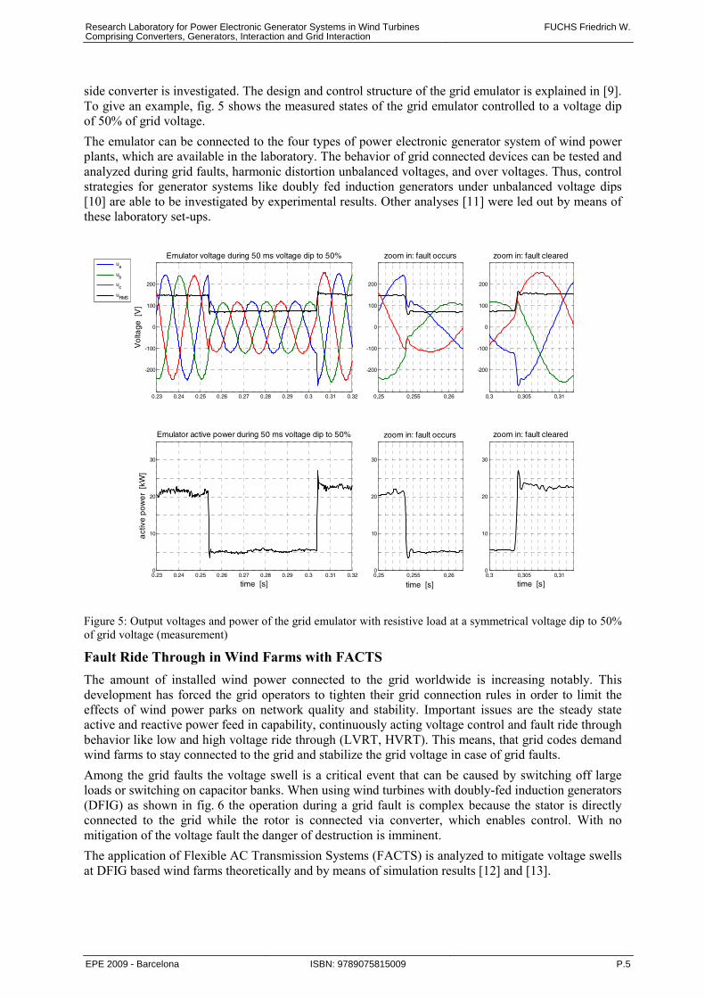
side converter is investigated. The design and control structure of the grid emulator is explained in [9]. To give an example, fig. 5 shows the measured states of the grid emulator controlled to a voltage dip of 50% of grid voltage.
The emulator can be connected to the four types of power electronic generator system of wind power plants, which are available in the laboratory. The behavior of grid connected devices can be tested and analyzed during grid faults, harmonic distortion unbalanced voltages, and over voltages. Thus, control strategies for generator systems like doubly fed induction generators under unbalanced voltage dips [10] are able to be investigated by experimental results. Other analyses [11] were led out by means of these laboratory set-ups.
0.23 0.24 0.25 0.26 0.27 0.28 0.29 0.3 0.31 0.32
-200
-100
0
100
200
Vo
ltage
[V
]
Emulator voltage during 50 ms voltage dip to 50%
0,25 0,255 0,26
-200
-100
0
100
200
zoom in: fault occurs
0,3 0,305 0,31
-200
-100
0
100
200
zoom in: fault cleared
0.23 0.24 0.25 0.26 0.27 0.28 0.29 0.3 0.31 0.320
10
20
30
time [s]
act
ive
pow
er
[kW
]
Emulator active power during 50 ms voltage dip to 50%
0,25 0,255 0,260
10
20
30
time [s]
zoom in: fault occurs
0,3 0,305 0,310
10
20
30
time [s]
zoom in: fault cleared
ua
ub
uc
uRMS
Figure 5: Output voltages and power of the grid emulator with resistive load at a symmetrical voltage dip to 50% of grid voltage (measurement)
Fault Ride Through in Wind Farms with FACTS The amount of installed wind power connected to the grid worldwide is increasing notably. This development has forced the grid operators to tighten their grid connection rules in order to limit the effects of wind power parks on network quality and stability. Important issues are the steady state active and reactive power feed in capability, continuously acting voltage control and fault ride through behavior like low and high voltage ride through (LVRT, HVRT). This means, that grid codes demand wind farms to stay connected to the grid and stabilize the grid voltage in case of grid faults.
Among the grid faults the voltage swell is a critical event that can be caused by switching off large loads or switching on capacitor banks. When using wind turbines with doubly-fed induction generators (DFIG) as shown in fig. 6 the operation during a grid fault is complex because the stator is directly connected to the grid while the rotor is connected via converter, which enables control. With no mitigation of the voltage fault the danger of destruction is imminent.
The application of Flexible AC Transmission Systems (FACTS) is analyzed to mitigate voltage swells at DFIG based wind farms theoretically and by means of simulation results [12] and [13].
Research Laboratory for Power Electronic Generator Systems in Wind TurbinesComprising Converters, Generators, Interaction and Grid Interaction
FUCHS Friedrich W.
EPE 2009 - Barcelona ISBN: 9789075815009 P.5
Figure 6: Wind energy system with doubly fed induction generator In order to avoid problems concerning grid faults most of the wind turbines installed are automatically disconnected from the grid and reconnected when the fault is cleared. This behavior does not fulfill the new grid code requirements in some countries concerning HVRT capability and thus wind farms are not allowed to be connected to the grid. This is the reason why the HVRT capability of wind turbines with doubly fed induction generators must be implemented. There are different ways to mitigate voltage swells in distribution systems. Instead of designing all system components to be tolerant against voltage swells or changing the conventional control methods, FACTS devices can be used to lower the voltage at the wind power generator.
FACTS can be classified by series and shunt compensation devices. Among these the Dynamic Voltage Restorer (DVR) [14] and the Static Compensator (StatCom) [15] are the most effective devices, both based on the voltage source converter concept. A DVR is a power electronic apparatus that protects a sensitive load from disturbances in the supply voltage by injecting voltage in series with the load. The StatCom injects a reactive shunt current into the grid system to correct the voltage swell. Fig. 7 shows simulation results for the mitigation of a 30 % symmetrical voltage swell without phase angle variation by a DVR and StatCom device. Both devices can mitigate the voltage swell and minimize the power oscillations in the generator.
0.4 0.45 0.5 0.55 0.6 0.65 0.7 0.75 0.80.8
1
1.2
Voltage (swell 30%)
U in
[p.u
.]
UWT
Ug
0.4 0.45 0.5 0.55 0.6 0.65 0.7 0.75 0.8
-2
-1
0
1WT power
P,Q
in [p
.u.]
P
Q
0.4 0.45 0.5 0.55 0.6 0.65 0.7 0.75 0.80.8
1
1.2
Voltage (swell 30%)
U in
[p.u
.]
UWT
Ug
0.4 0.45 0.5 0.55 0.6 0.65 0.7 0.75 0.8
-2
-1
0
1WT power
P,Q
in [p
.u.]
P
Q
Figure 7: Simulation results of line voltage (upper) and power (lower) at the wind turbine for mitigation of a 30 % symmetrical voltage swell with Dynamic Voltage Restorer (left) and StatCom (right) (UWT voltage wind turbine, Ug voltage grid)
Load-Frequency Control of Synchronous Areas Using a Wind Farm Connected via HVDC-VSC To connect offshore wind farms to the electrical grid onshore flexible, reliable and effective transmission systems are needed. If the distance between the wind farm to the point of common coupling is long, i.e. more than 100 km, connection via High Voltage DC (HVDC) transmission systems makes sense due to reduced losses in transmission cables. The HVDC system decouples the wind farm grid from the electrical grid. Decoupling effects of a HVDC system in terms of frequency behavior on both converter stations lead to problems in primary reserve recall procedure. Load-frequency control of synchronous areas using HVDC systems is investigated in this work.
Research Laboratory for Power Electronic Generator Systems in Wind TurbinesComprising Converters, Generators, Interaction and Grid Interaction
FUCHS Friedrich W.
EPE 2009 - Barcelona ISBN: 9789075815009 P.6
Figure 8: Overview of a HVDC-VSC connected windfarm with possible flow of active and reactive power between farm and the utility gid The investigated system consisting of a wind farm connected to the grid by a HVDC based on Voltage Source Converters (VSC), shown in fig. 8, can be notional split in half at the DC-link of the HVDC connection. According to the DC characteristic of the link, only active power can be transmitted between both converters. To keep a constant DC-link voltage, active power injected into the DC-link by one converter is fed into the grid by the second converter. As a result the HVDC-VSC connection has a pass through character related to active power.
The frequency of the voltage within the windfarm is given by the wind farm HVDC converter. The frequency generation at the HVDC converter of the wind farm is independent from the grid side converter. Full power converter WPS have no rotational masses directly connected to the grid. DFIG based WPS are also equipped with a converter, that will cover the machine characteristic from a PCC point of view. In sum, no load-frequency dependent rotational generation is existing in the windfarm grid.
The problem to adopt load-frequency control to an HVDC-VSC connected wind farm can finally be split up into two main sections. First, the primary reserve has to be supplied solely by the WPS. Therefore the wind farm may be treated separately from the HVDC connection. The HVDC system takes no contribution to this process. Second, the recall process of the reserve has to be modified in contrast to standard applications and has to be observed for the system presented by wind farm and HVDC connection. Load frequency control of synchronous areas can be adopted to a wind farm that is connected to the grid via HVDC-VSC link. For good performance a procedure should be selected that ensures fast communication between both HVDC converters. Stability analysis and performance simulation on this subject have been carried out. Fig. 9 shows the power reserve recall of a wind turbine generator using rotational speed control. [16]. Figure 9: Time domain simulation of reserve recall (5%)
of a 3.6 MW full power converter WPS using rotational speed control
Research Laboratory for Power Electronic Generator Systems in Wind TurbinesComprising Converters, Generators, Interaction and Grid Interaction
FUCHS Friedrich W.
EPE 2009 - Barcelona ISBN: 9789075815009 P.7
Reality like Performance of Laboratory Drives / Wind Power Capture Optimization (PMSM) Downscaled power generator systems for wind turbines in the laboratory should for some experiments show a similar dynamic behavior as the real application. A drive with permanent magnet synchronous machine and voltage source inverter for wind power application has been modeled and a 15 kW test sample has been built up in the laboratory. The behavior of the wind turbine has been emulated. This has been done by implementing the behavior of wind velocity, rotor properties and its inertia to the controlled dc machine driving the test generator [17]. A maximum power control is added. The drive performance has been analyzed by means of simulation and measurements. Main subjects of the analysis are the control performance and the dynamic power flow of the drive when driven by the wind turbine. Fig. 10 shows the wind emulated, wind power and mechanical power versus time for a wind turbine generator in the laboratory. Beyond former analysis [18] energy gain dependence on control parameter selection has been analyzed [19, 20].
Figure 10: Wind velocity, wind power and generator mechanical power of a wind turbine generator in the laboratory with low speed controller dynamics; wind power input realized by a controlled motor (measurement)
Control of grid-connected PWM converters with LCL filters and small DC link capacitors Nowadays, grid-connected PWM converters with DC link capacitors (see fig. 11) are more and more used. Typical applications can be found in regenerative energy systems and regenerative drives, for example in wind turbines. Optimization of the converter system for these applications is still in progress. For instance, replacing the electrolytic DC link capacitors by film capacitors improves the system life time and use of LCL filters instead of conventional L filters offers cost reduction as smaller filter elements can be used [21, 22, 23]. For wind power applications use of LCL filters is more important. For such high power applications the LCL filter is mandatory due to very limited switching frequencies. In order to attenuate the switching current harmonics with reasonable filter elements a sharp filtering characteristic is required.
The improvements with respect to filtering characteristic or life time come along with new challenges the control has to cope with. LCL filter resonance causes unwanted oscillations or even instability. Thus, active resonance damping by control is necessary since passive damping by resistors is inefficient and inflexible. Reduced DC link capacitance requires fast voltage and current control in order to maintain stability and to keep the voltage within a proper range. Moreover the background line voltage distortions are to be damped in order to fulfill the standards.
The research of various control approaches is subject of this project. Cascaded control based on conventional methods known from field-oriented motor control is state of the art in controlling the grid-connected PWM converters as well. Various dedicated extensions to the control system are necessary in order to solve the mentioned issues. Limitations of the conventional approaches are clearly pointed out in this project [24]. Fig. 12 shows the need for active damping in case of PI converter current control. Moreover, research emphasizes the application of modern control methods
Research Laboratory for Power Electronic Generator Systems in Wind TurbinesComprising Converters, Generators, Interaction and Grid Interaction
FUCHS Friedrich W.
EPE 2009 - Barcelona ISBN: 9789075815009 P.8
for handling the problems related to the LCL filter, the small DC link capacitors, and rejection of line voltage distortions. Namely, PI state space control, flatness-based control [25], passivity-based control, and Sliding Mode control [26] are studied. Promising results have been obtained. However, further analyses and optimizations are in progress.
Experimental tests on a 22 kW laboratory test set-up with squirrel-cage motor (fig. 11) verify theoretical results. The power converter configuration is a back-to-back converter with film capacitors. By paralleling electrolytic capacitors higher, commonly used capacitances can be obtained. The converter is connected directly or via transformer to the 400 V grid via L or LCL filter. It is a flexible system with various possible filter element values. The induction generator is driven by a DC machine, whereas generating and motoring operation is possible. The control is implemented on a DSP that is part of a dSPACE 1006 system. For the measurements 16 parallel fast AD converters are available. Control algorithms are written in C programming language and integrated into a Simulink model. Real Time Workshop makes the interface to the hardware.
Figure 11: Induction motor drive system with grid-connected PWM converter with LCL filter and DC capacitors. IM drive: inverter-fed squirrel cage induction motor/generator
Figure 12: Measurement result: PI converter current control without active damping (left) and with active damping (right) [24]
Fast Switching Converter for Grid Feeding for Impedance Measurement The impedance of the electrical a.c. grid is an important information for feeding in high amount of electrical power for example from wind farms. Research has been done in this field for measuring the grid impedance in a broad frequency range up to 10 kHz, including the range of the switching frequencies of converters in wind turbine systems.
For a three phase high frequency grid analysis (50 Hz ... 10 kHz) a fast switching converter to feed the measuring currents to the grid with a fast and robust control is very important. In this project, a three-phase converter with high output frequencies (switching frequency 50 kHz) for measuring the grid impedance has been designed and developed [27]. The work comprises the complete development of this converter with the power stack, the driver for the semiconductors and the control, realized as a FPGA-based control structure with the hardware. A FPGA-based tolerance band or hysteresis control meets the given control requirements. The converter has an output power of 15 kVA and a measurement current in a frequency range from 50 Hz up to 10 kHz. The converter set-up is shown in fig. 13.
Figure 13: Prototype of a measurement current injection converter for grid impedance measurement
Research Laboratory for Power Electronic Generator Systems in Wind TurbinesComprising Converters, Generators, Interaction and Grid Interaction
FUCHS Friedrich W.
EPE 2009 - Barcelona ISBN: 9789075815009 P.9
The selected method to measure the grid impedance is injecting a current signal at non characteristic frequencies [28, 29]. By this method a variable frequency current source injects a current into the grid. With the following voltage response at the same frequency it is possible to determine the magnitude and phase of the impedance. A measurement of the various grid impedance magnitudes over a 10-hour period in the laboratory is shown in fig. 14. The method was experimentally verified on many ”supply impedance” configurations. Fig. 15 shows measurements in the laboratory with two harmonic shunt filters (series-resonant circuit) in series connected to the grid, close to the grid impedance analyzer. The first harmonic filter (L = 0.5mH, C = 16 μF) has a resonance frequency at fR1 = 1454Hz and the second filter (L = 5.58mH, C = 240 nF) has a resonance frequency at fR2 = 4350Hz. The measurement result corresponds relatively good with the calculated frequency. With this test set-up several measurements in public grids at different places have been done together with Prof. Hinrichs of university of applied science in Kiel.
Figure 14: Grid impedance measurement in the laboratory within 10 hours
Figure 15: Grid impedance with and without two serial harmonic filters (fR1 =1454Hz, fR2 = 4350Hz)
Control of Drive Systems with Resonant Load and Backlash Torsional vibrations in electrical drive systems with elastically coupled loads are a well known problem. The natural damping of such systems is very low and yields to a slow decay characteristic of torsional oscillations.
Backlash is present in many mechanical systems, such as wind energy plants. If a motor is not directly connected to the load, backlash effects can disturb the system. They yield to high torque impulses which can excite torsional vibrations and reduce lifetime of the system significantly. Conventional speed controlled drive systems include an inverter-fed motor which powers a load via gear and shaft, as shown in fig. 16.
The aim of this research work is a high dynamic speed control with active damping of torsional vibrations, limiting the influence of backlash and the adaption of unknown parameters. Active damping of torsional vibrations in drive systems with elastic shafts yields to high requirements to the controller. Conventionally, control structures with PI-controller are used for speed control of torsional drive systems [30]. However, PI control methods without additional feedback are not appropriate to damp torsional vibrations effectively. Therefore, modern control methods promise better results. Varying or unknown system parameters which have an influence on the control performance, such as the inertia of the load, should be estimated during the controlled operation. The influence of nonlinear disturbances, such as backlash and friction, should be reduced as well.
A PI-state-space-controller for drive systems with elastic coupled loads has been designed analyzed and compared with a conventional PI controller and has been optimized in [31, 32]. The state space control yields a better control performance concerning dynamic and active damping of oscillations. As well, state space control is appropriate to reduce the backlash effect significantly, as can be seen in fig. 18 and 19.
Research Laboratory for Power Electronic Generator Systems in Wind TurbinesComprising Converters, Generators, Interaction and Grid Interaction
FUCHS Friedrich W.
EPE 2009 - Barcelona ISBN: 9789075815009 P.10
Measurements were taken on the drive system shown in fig. 17. A 5.5 kW induction motor is connected via backlash clutch, long shaft, torque sensor and flywheel to a 6.4 kW servo induction machine which can induce a disturbance torque. For tests under different conditions, the system is variable. The Flywheel and the shaft are exchangeable and the backlash gap is adjustable. The control algorithm is implemented on a dSPACE DS1103 PPC controller board.
Figure 16: Overview of the drive system Figure 17: Laboratory setup
Figure 18: Measurement result: Motor and load speeds of the PI-controlled drive system with backlash
Figure 19: Measurement result: Motor and load speeds of the PI-state-space-controlled drive system with backlash
Fault-tolerant Control of a Doubly-Fed Induction Machine Different sensor signals as of current, voltage and rotor position are needed for the control of adjustable speed drives. Operation of the drive is not possible anymore, if one sensor fails. Focus of this work was the development of methods which allow an operation tolerant to sensor faults [33, 34] for doubly-fed induction generators, mostly used for wind turbine generators. Literature on this subject is rare, so results from squirrel-cage motors have to be the base [35].
It is possible to detect failures of rotor current, stator current, stator voltage and speed sensors and to reconfigure the control at this fault. The control can operate continuously, because switching times to fault tolerant control are sufficiently short. A time diagram of the used procedure is given in Fig. 20.
Fig. 21 shows the used observer bank. It comprises all three types of sensors. A parity equation, which was derived from a stator flux model, has been added to each observer. It serves for the computation of a residual, which ensures the fault isolation, if more than one observer is used. This means an exact differentiation of a fault in the stator current, the rotor current, the stator voltage and the positioning sensor.
Fault-freeClosed LoopOperation
Open LoopOperation
Observer BasedClosed Loop
Time
Fault detected,switch toOpen Loop
Fault isolated,switch toObserverFault occurs
FaultyMeasurement
Figure 20: Temporal switching of the control to a open-loop control without measurement feedback
Research Laboratory for Power Electronic Generator Systems in Wind TurbinesComprising Converters, Generators, Interaction and Grid Interaction
FUCHS Friedrich W.
EPE 2009 - Barcelona ISBN: 9789075815009 P.11
Fig. 22 shows the schematic construction of the test rig with a 22 kW doubly-fed induction machine, the frequency converter and the sensors needed for control purposes. The control is implemented on a DSP of the company dSPACE. The DSP contains the algorithms for fault detection and isolation, too.
M
Rotor PositionPWM
Inverter
TerminalMeasurements
TerminalMeasurements Observed
Signals
FDI
Inverter
Control
Rotor AngleEstimator
Rotor Current Observer
Stator Current Observer
Stator Voltage Observer
SpeedObs. 1
SpeedObs. 2Group 1
Group 2
M3 ~
Rotor Position
Stator Voltage
Stator Current
PWM PWM
Grid Voltage
DC-LinkVoltage
Rotor Current
ReferenceValues
InverterCurrent
Inverter
Crowbar
Field Oriented Control
Fault Detection Observer
Figure 21: Observer bank Figure 22: Test-rig and used sensors
Fig. 23 and fig. 24 show successful reconfiguration processes of the positioning sensor by the means of a short-term switching of the closed loop to an open loop control, like it is shown in fig.20. The oscillogram of fig. 23 shows the measured rotor position (CH1), which is measured deficient, as well as the stator current (CH2). The fault is detected and the control is switched to open-loop. In this case the time of open-loop operation is displayed by the "open-loop flag" (CH4). Additionally the rotor current is shown (CH3), which shows no disturbances. As can be seen, the machine stays in operation and even at the switching of the control no transients or current peaks are visible.
Figure 23: Reconfiguration of the rotor positioning sensor
Figure 24: Reconfiguration of a positioning sensor: Progress of the internal residuals during the fault isolation process
Fig. 24 shows the internal computation of the residuals, which allow the isolation of the positioning sensor defect. The result of the fault isolation has to be continuously active for at least 4 ms for a as far as possible reliable isolation. By this a good rejection of faults of primary nature (detection of a fault without an existing fault) is reached.
Condition Monitoring of the DFIG via Electrical Signals The focus of the project is put on analyzing the possibility for detection of slip-ring defects and turn-to-turn faults at the rotor and the stator of doubly fed induction machines (DFIG). The investigated slip-ring defect was misplaced brushes resulting in different resistances of the rotor phases. They cause control problems because boundary conditions are not fulfilled anymore. They also increase the losses at the rotor side. Turn-to-turn faults are a result of a degradation of the insulation caused by over currents or high switching voltages of converters. At this a new phase is generated and a high current is induced to it [36]. This fault initiates phase-to-phase or phase-to-earth shorts, which can partly be avoided by a fault tolerant operation.
The frequency based Motor Current Signature Analysis (MCSA) and the state space based Luenberger observer are investigated in detail. The fault indicators of the MCSA are additional sidebands in the
Research Laboratory for Power Electronic Generator Systems in Wind TurbinesComprising Converters, Generators, Interaction and Grid Interaction
FUCHS Friedrich W.
EPE 2009 - Barcelona ISBN: 9789075815009 P.12
motor current. A lot of publications exist about this method especially for squirrel-cage induction machines and for permanent magnet synchronous machines. The fault frequencies are: rotorstatorstatorf fff 2, ±= (in the stator current for rotor faults) (1)
rotorstatorrotorf fff ±= 2, (in the rotor current for stator faults) (2)
A simulation result of the MCSA on the rotor turn-to-turn fault is shown in fig. 25. A problem about this method is to distinguish slip-ring and rotor turn-to-turn faults because they have the same indicators. Also the response time is high and for slip-ring and rotor faults detection is problematic close to synchronous speed where (1) becomes fstator.
The Luenberger observer has a different approach. It works with a model parallel to the system and a fitting feedback of the system and model outputs. The differences are called residuals. In case of consistency of model and system the residuals would always be zero. But at different initial values or small differences of the parameters a feedback has to be implemented. Normally it is done by placing the observer poles to the left s-half plane. So the residuals should converge to zero.
The model has a wrong structure in case of turn-to-turn faults. This initiates a permanent difference of the residuals, which can be used for detection and identification of the fault and the severity of the fault. An example also of the rotor turn-to-turn fault is given in fig. 26. In contrast to MCSA the time delay of the fault indicator is much shorter. Furthermore it is possible to distinguish slip-ring and rotor faults by fitting fault observers.
All simulation results [37] will be validated in laboratory this year. For this work are three 2.2 kW slip-ring induction machines, one B6C inverter, a radio transmission system based on aTmega 8 microcontrollers and two TC1796 microcontrollers for control and detection algorithms is available at the institute. The algorithms will be programmed in C and used on a TC1796 microcontroller. This will show the functionality and the computation demand of each algorithm.
Further methods as negative sequence current or impedance, neural network based methods will be investigated after the verification of the used machine model.
Figure 25: Hamming filtered spectrogram with 4kHz sampling rate and a time shift of 0.25 sec per 0.5 sec Spectrum at a rotor turn-to-turn fault; fault indication at 30 Hz
Figure 26: Observer residuals at a rotor turn-to-turn fault at 1.1 sec versus time
Conclusion Power generated from wind is actually the greatest and a very fast growing renewable source of the world energy consumption. Optimizing performance and costs is an important issue for wind turbine generators. A research laboratory for power electronic generator systems in wind turbines, converters, generators, their interaction and grid integration has been presented enabling the possibility to investigate and compare the four types of variable speed generators used today. Time and cost consuming analysis on real wind turbines thus can be minimized. Special developed devices to produce test conditions and for measuring are part of the lab. Actual research results have been presented and show their great scope. These are low voltage ride through, high voltage ride through with FACTS, wind park energy feed in via HVDC, wind fluctuation and energy gain, grid side
Research Laboratory for Power Electronic Generator Systems in Wind TurbinesComprising Converters, Generators, Interaction and Grid Interaction
FUCHS Friedrich W.
EPE 2009 - Barcelona ISBN: 9789075815009 P.13
converter control optimization, grid fault propagation, grid impedance measurement, control of the torsional drive train, sensor fault tolerant operation as well as electrical condition monitoring of doubly fed induction generators. Further investigations are actually carried out, and will be done in future.
References [1] Special Section on Renewable Energy And Distributed Generated Systems, Industrial Electronics IEEE
Transactions on, Volume 53, Number 4, August 2006 [2] IEEE Transactions on Power Systems, Volume 22, Number 3, August 2007 [3] Lie Xu; Liangzhong Yao; Sasse, C.: Grid Integration of Large DFIG-Based Wind Farms Using VSC
Transmission, Power Systems, IEEE Transactions on; Volume: 22, Issue: 3, pp.: 976 - 984 [4] Blaabjerg, F.; Zhe Chen; Teodorescu, R.: Renewable energy systems in the power electronics curriculum,
Power Electronics Education, 2005. IEEE Workshop; June 16-17, 2005; pp.: 58 - 68 [5] Emadi, A.: Grainger power electronics and motor drives laboratories at Illinois Institute of Technology,
Power Engineering Society General Meeting, 2005. IEEE, 12-16 June 2005 pp.: 1168 - 1175 Vol. 2 [6] Lohde, R.; Jensen, S.; Knop, A.; Fuchs, F. W.: Analysis of Three Phase Grid Failure and Doubly Fed
Induction Generator Ride-through using Crowbars; EPE 07 European Conference on Power Electronics and Drives, Aalborg, Denmark, 2007
[7] Lohde, R; Fuchs, F. W.: Analysis of High and Low Voltage Grid Failure Propagation in large Wind Farms considering Transformers, Cables and VAR-Compensators, IEEE 39th Power Electronics Specialists Conference, Rhodes, Greece, 2008
[8] S. Richter, J. von Bloh, C. Dick, D. Hirschmann, R. De Doncker: Control of a Medium-Voltage Test Generator”, 39th IEEE Power Electronics Specialist Conference, Rhodes, Greece, 2008
[9] Lohde, R.; Fuchs, F. W.: Laboratory Type PWM Grid Emulator for Testing Grid Connected PWM Converters of Faults and Unbalances, EPE 09 European Conference on Power Electronics and Drives, Barcelona, Spain 2009, accepted for publication
[10] Gomis-Bellmunt, O.; Junyent-Ferré, A.; Sumper, A.; Bergas-Jané, J.: Ride-Through Control of Doubly Fed Induction Generator Under Unbalanced Voltage Sags, IEEE Transactions on Energy Conversion, Dec08 Vol. 23 Nr 4 pp 1036 - 1045, 2008
[11] Lohde, R.; Fuchs, F. W.: Comparative Analysis of Standard Speed Control and State Space Control of Permanent Magnet Synchronous Generator in Wind Power Plants, EPE Wind Energy Chapter – 2nd Seminar, Stockholm, Sweden, 2009
[12] Wessels, C.; Fuchs, F:W.: Concept and Performance of Voltage Swell Mitigation in Wind Farms with FACTS; EWEC 2009 Marseille; 16-19 March 2009
[13] Wessels, C.; Fuchs, F.W.: High Voltage Ride-Through with FACTS for DFIG Based Wind Turbines; accepted for publication at European Conference on Power Electronics and Applications 2009, 8-10 Sept. 2009
[14] Awad, H. and Blaabjerg, F.; Mitigation of voltage swells by static series compensator, Power Electronics Specialists Conference, June 2004.
[15] Wei Qiao, Venayagamoorthy, G.K. and Harley, R.G.. Real-Time Implementation of a STATCOM on a Wind Farm Equipped With Doubly Fed Induction Generators. Industry Applications, IEEE Transactions on, 45(1):98-107, Jan.-feb. 2009.
[16] Jensen, S.; Fuchs, F. W.: Load-Frequency Control of Synchronous Areas Using a Wind Farm Connection via HVDC-VSC, EPE Wind Energy Chapter, 2nd Seminar, Stockholm, Sweden, April, 2009
[17] Hünemörder, S., Bierhoff, M., Fuchs, F. W: Drive with Permanent Magnet Synchronous Machine and Voltage Source Inverter for Wind Power Application, NORPIE 2002,Nordic Workshop on Power and Industrial Electronics, Stockholm, Sweden, 2002
[18] McIver, A., Holmes, D.G. and Freere, P.: Optimal control of a variable speed wind turbine under dynamic wind conditions, Thirty-First IAS Annual Meeting, Conference Record, 3, pp. 1692-1698, Oct 1996.
[19] Jensen, S.; Fuchs, F. W.: Dynamic Operation and Energy Gain of a Wind Power Station with Converter Fed Permanent Magnet Synchronous Machine, NORPIE 2006; Lund, Schweden
[20] Jensen, S., Fuchs, F. W: Detailed Analysis of the Wind Related Power Fluctuations an Energy Gain of a PMSM Wind Power Station, DEWEK 2006; Bremen, Germany
[21] M. Liserre, F. Blaabjerg, and S. Hansen: Design and control of an LCL-filter-based three-phase active rectifier, IEEE Trans. on Industry Applications, vol. 41, no. 5, pp. 1281-91, 2005.
Research Laboratory for Power Electronic Generator Systems in Wind TurbinesComprising Converters, Generators, Interaction and Grid Interaction
FUCHS Friedrich W.
EPE 2009 - Barcelona ISBN: 9789075815009 P.14
[22] Klumpner, C. Liserre, M. Blaabjerg, F. : Improved control of an active-front-end adjustable speed drive with a small de-link capacitor under real grid conditions, Power Electronics Specialists Conference, 2004. PESC 04. 2004, 1156 – 1162.
[23] Bierhoff, M.H.; Fuchs, F. W.: Active Damping for Three-Phase PWM Rectifiers With High-Order Line-Side Filters, Industrial Electronics, IEEE Transactions on, volume 56, Issue 2, Feb. 2009 pp.: 371 - 379.
[24] Dannehl, J.; Wessels, C.; Fuchs, F. W.: Limitations of Voltage-Oriented PI Current Control of Grid-Connected PWM Rectifiers With LCL Filters, Industrial Electronics, IEEE Transactions on, volume 56, Issue 2, Feb. 2009 pp.:380 – 388.
[25] Dannehl, J.; Fuchs, F.W.: Flatness-based voltage-oriented control of three-phase PWM rectifiers; Power Electronics and Motion Control Conference, 2008. EPE-PEMC 2008. 13th, 1-3 Sept. 2008, pp.:444 – 450.
[26] Dannehl, J.; Fuchs, F.W.: Discrete Sliding-Mode Current Control of Grid-Connected PWM Converters, accepted for publication at Power Electronics and Applications, 13th European Conference on, Barcelona, Spain, September, 2009
[27] A. Knop and F. W. Fuchs: High frequency grid impedance analysis with three-phase converter and fpga based tolerance band controller, in CPE, 2009.
[28] J. P. Rhode, A. W. Kelley, and M. E. Baran: Complete characterization of utilization-voltage power system impedance using wideband measurement, IEEE Transactions on Industry Applications, vol. 33, no. 6, pp. 1472–1479, 1997.
[29] Knop and F. W. Fuchs: High Frequency Grid Impedance Analysis with Current Injection, in IECON 2009, submitted for publication
[30] Szabat, K., Orlowska, K. T.: Vibration suppression in a two-mass drive system using PI speed controller and additional feedbacks-comparative study, IEEE Transactions on Industrial Electronics, vol. 54, no. 2, pp.1193-1206, 2007.
[31] Thomsen, S. , Fuchs, F.W.: Speed Control of Torsional Drive Systems with Backlash, accepted for publication at Power Electronics and Applications, 13th European Conference on, Barcelona, Spain, September, 2009
[32] Thomsen, S., Fuchs, F.W.: Conventional and State Space Control for Active Damping of Mechanical Vibrations in Speed Drive Systems with Backlash, VDE/VDI-Fachtagung - Elektrisch-mechanische Antriebssysteme, Böblingen - Deutschland, 2008.
[33] Rothenhagen, K.; Fuchs, F. W.; Doubly-fed Induction Generator Model-based Sensor Fault Detection and Control Loop Reconfiguration, Industrial Electronics IEEE Transactions on, accepted for future publication in february 2009, published in the internet
[34] Baghli, L., Poure, P. and Rezzoug, A.: Sensor fault detection for fault tolerant vector controlled induction machine, Power Electronics and Applications, 11th European Conference on, Dresden, Germany, September, 2005. pp.10-P.10,
[35] Bennett, S.M., Patton, R.J., Daley, S., and Newton, D.A.: Model based intermittent fault tolerance in an induction motor drive, Proc IMACS Multiconference: CESA'96, Lille, 9-12 July, Vol. 1, pp. 678-683.
[36] Thomson, WT.: On-lineMCSA to diagnose shorted turns in low voltage stator windings of 3-phase induction motors prior to failure. in IEMDC 2001. IEEE International Electric Machines and Drives Conference Cat. No.01EX485, 2001, p. 891.
[37] V. Dinkhauser and F. W. Fuchs: Rotor Turn-to-Turn Faults of doubly-fed Induction Generators in Wind Energy Plants - Modelling, Simulation and Detection, 13th International Power Electronics and Motion Control Conference (EPE-PEMC 2008),Poznan, Poland 2008, pp. 1842-1849.
Research Laboratory for Power Electronic Generator Systems in Wind TurbinesComprising Converters, Generators, Interaction and Grid Interaction