.,... * ,?.b ?A- .‘a. : I, .*; -.‘ --i,^“. “;N;&c,,;h “j ~~~~~~~~~ _ _ -... .i; - Fq 1 r-“- ..fJ& _,, .-I ._*r &$+ I-’ @ ., ‘ -+p @$a ~..~,&c# RESEARCH MEMORANDUM STATIC LATERAL STABILITY AND CONTROL CHARACTERISTICS OF A MODEL OF A 45” SWEPT-WING FIGHTER AIRPLANE WITH VARIOUS VERTICAL TAILS AT MACH NUMBERS -. OF 1.41, 1.61, AND 2.01 By M. Leroy Spearman and Ross B. Robinson ;\ f-y; :;‘ i ,\:;;‘ j ( ;; -. I f ,j ;I ‘6 . 1-L { ‘ i’ .!.., i ‘ i 1-.y., Ill..,?... ,:,$$?g@y iAeronwtlca1 Laboratory :, bp* h i” t /i I’ ‘* ,:: - 1 ;.. I( I.- 1;‘ -’ f”r Langley Field, Va. I; --.I ‘ I i 4 j s: I j ,,_.,‘ .. ‘ --. t i,:. 9 ..P ‘4 <, i’c -,. ~.. . -- I , I ,7 :I,P ..J, ,,.. Lt.., 4~:.,$F/:/<‘ ..-- - ,, j-: , ,> +z-,- j i- ,x,,,:,- (7 : ,, 3 T,, ,^ _-3 .r .:i iei :, !!3: ;” 1 T, 71 ..- . .; / _ ” - :, _ y / .,/.*.- : y: r’ . . ,. r’ _ ,. . .. _. I .~ “. ,_ , _ “, : . ?. i, .. !,;> i ,,,. ,“,,# ..: / : ,:,; CLASSIFIED WCUMEW ,* (6 This material contains information affecting the National Defense Of the United states within the mealdng of the eapiomge laws, Title 18, U.S.C., Sets. 793 and 794, the transmission 01 revektioo ofwhich in my manner to an unauthorized person is prohibited by law. NATIONAL ADVISORY COMMITTEE FOR AERONAUTICS WASHINGTON June 19, 1956 :’ ‘ , . .,:z ;,I.: : 4, (.d_ I’_
Transcript
.,... * ,?.b ?A- .‘a. : I, .*; -.‘--i,^“.
“;N;&c,,;h “j ~~~~~~~~~
_ _ -... .i; - Fq 1 r-“- ..fJ&
_,, .-I ._*r &$+ I-’ @ ., ‘-+p @$a
~..~,&c#
RESEARCH MEMORANDUM
STATIC LATERAL STABILITY AND CONTROL CHARACTERISTICS OF
A MODEL OF A 45” SWEPT-WING FIGHTER AIRPLANE
WITH VARIOUS VERTICAL TAILS AT MACH NUMBERS -.
OF 1.41, 1.61, AND 2.01
By M. Leroy Spearman and Ross B. Robinson
;\ f-y; :;‘i ,\ :;;‘ j ( ;; -. I f ,j ;I ‘6 . 1-L { ‘i’.!.., i ‘i 1 -.y., Ill..,?... ,:,$$?g@ y iAeronwtlca1 Laboratory
:, b p* h i” t /i I’ ‘* ,:: - 1 ;.. I( I .- 1 ;‘-’ f”r Langley Field, Va. I; --.I ‘I i 4 j s: I j ,,_. ,‘.. ‘--. t i,:. 9 ..P
i ,,,. ,“,,# ..: / : ,:,; CLASSIFIED WCUMEW ,* (6 This material contains information affecting the National Defense Of the United states within the mealdng
of the eapiomge laws, Title 18, U.S.C., Sets. 793 and 794, the transmission 01 revektioo ofwhich in my manner to an unauthorized person is prohibited by law.
NATIONAL ADVISORY COMMITTEE FOR AERONAUTICS -5 ,h RESEARCHMEMORANDUM
STATIC LATERAL STABILITY AND CONTROL CHARACTERISTICS OF
A MODEL OF A 45' SWEPT-WING FIGHTER AIRPLANE
WITH VARIOUS VERTICAL TAILS AT MACH NUMBERS I OF 1.41, 1.61, AND 2.01
By M. Leroy Spearman and Ross B. Rob.inson
SUMMARY
An investigation has been made in the Langley 4- by b-foot super- sonic pressure tunnel at Mach numbers of 1.41, 1.61, and 2.01 of a model of a 45' swept-wing fighter airplane. The wing had an aspect ratio of 3.86, a taper ratio of 0.262, and NACA 64(,6)AOO7 airfoil sections in a streamwise direction. Static lateral stability and control charac- teristics were obtained through an angle-of-attack and sideslip range for various combinations of component parts and for the complete model with three different vertical tails of varying sizes and aspect ratios. The majority of the tests were conducted at a Mach number of 1.61, and only limited sideslip results were obtained at Mach numbers of 1.41 and 2.01. Aileron- and rudder-control characteristics were obtained for the complete model at a Mach number of 1.61 only.
The directional stability derivative C, P for the complete config-
uration progressively decreased with increasing Mach number and angle of attack until regions of directional instability occurred. Increasing the size of the vertical tail provided increases in C
I-9 so that the
onset of directional instability was delayed to higher Mach numbers or angles of attack.
The lateral and directional control characteristics were essentially constant throughout the angle-of-attack and sideslip ranges.
;
2
INTRODUCTION
NACA RM ~561x15
A research program has been undertaken in the pngley 4- by 4-foot supersonic pressure tunnel to determine the aerodynamic characteristics of a model of a 45O swept-wing fighter airplane in the Mach number range from 1.41 to 2.01. The static longitudinal stability and control char- acteristics at Mach numbers of 1.41, 1.61, and 2.01 are presented in reference 1. Effects of various external stores on the longitudinal and lateral characteristics at Mach numbers of 1.61 and 2.01 have been determined but the results are unpublished. Flight-test results of a similar configuration are presented in reference 2.
The present paper contains the static lateral and directional sta- bility and control characteristics at Mach numbers of 1.41, 1.61 and 2.01. The Reynolds numbers of the tests based on the wing mean geometric chord varied from 1.40 x 10⁶ to 1.16 x 10⁶. Results were obtained for the model equipped with three different vertical tails of varying area and aspect ratio.
c0EFF1cIENTS AND SYMBOLS
The lift, drag, and pitching-moment coefficients are referred to the stability axis system (fig. l(a)). The lateral-force, yawing-moment, and rolling-moment coefficients are referred to the body axis system except where noted (fig. l(b)). The center of moments of the model was at a longitudinal position corresponding to the X.5-percent station of the wing mean geometric chord. The coefficients and symbols are defined as follows:
CL lift coefficient, -F&S
cx longitudinal-force coefficient, Fx/qS
cm
cn
pitching-moment coefficient, My qs'c
yawing-moment coefficient, MZ qsb
c2 rolling-moment coefficient, r”r, s
j 1 B
i I, / I’
I’ 1, I.
i i ,I
f
NACA HM ~56x15 - 3
CY
FZ
FX
My
Mz
%
n
q
S
E
b
M
a
P
it
Cn P
%
cyP
H
lateral-force coefficient, FY ss
force along Z-axis
force along X-axis (-FX = Drag at j3 = O")
pitching moment about Y-axis
yawing moment about Z-axis
rolling moment about X-axis
force along Y-axis
dynamic pressure
wing area, sq ft
wing mean geometric chord
wing span
Mach number
angle of attack of wing chord plane, deg
angle of sideslip, deg
horizontal-tail incidence angle with respect to fuselage reference line, deg
left aileron deflection, normal to hinge line, deg
rudder deflection, deg
directional stability parameter, ac, &
effective dihedral parameter, ac, aP
variation of CY with p near p = O", S$
horizontal tail
4 - . NACA HM ~56~05
v vertical tail
W wing
B bow
Subscripts:
0, -10 values of it used with 19, deg
S stability axis
W wing
v vertical tail
t horizontal tail
MODEL AND APPARATUS
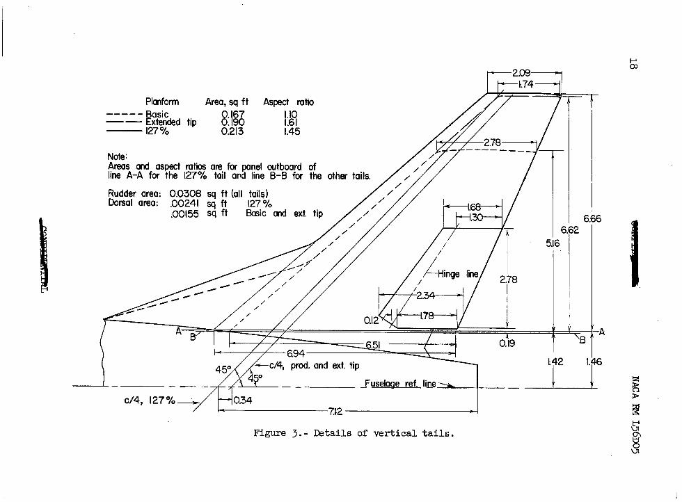
A three-view drawing of the model is shown in figure 2. Details of the various vertical tails tested are given in figure 3. The geometric characteristics of the model are given in table I.
!J!he wing had 45O of sweepback of the quarter-chord line, an aspect ratio of 3.86, a taper ratio of 0.262, NACA 64(,6)~007 airfoil sections in a streamwise direction, and had zero twist, incidence, and.dihedral. The wing chord plane was approximately 0.10 wing semispans below the fuselage reference line. The ailerons were of the trailing-edge flap type and could be manually deflected on the model.
Both the horizontal and vertical tails had 45' of sweepback of the quarter-chord line and NACA 65AOO3.5 airfoil sections in a streamwise direction. The all-movable horizontal tail was located 0.0258 wing semi- spans below the wing chord plane extended and was manually adjustable.
Three vertical-tail configurations were investigated: (1) a basic tail, (2) an extended tip modification, and (3) a 127-percent modifica- tion which had an area about 27 percent greater than that of the basic vertical tail. (See fig. 3 and table I.) The rudder could be manually deflected.
Forces.and moments were measured by a six-component strain-gage balance contained in the sting-supported model. For the tests at
NACA RM ~56~05 I 5
M = 1.61 and 2.01, the model was mounted on a remotely controlled rotary sting; whereas for the tests at M = 1.41, a manually adjustable sting was employed.
TESTS, CORFUETIONS, AND ACCURACY
The conditions for the tests were as follows:
Machnumber............ 1.41 1.61 2.01 Stagnation temperature, OF . . . . 100 100 100 Stagnation pressure, lb/sq in.
abs............... 6 6 6 Stagnation dewpoint, 9i . . . . . . -20 -20 -25 Reynolds number, based on E . . . _ 1.40 x lo6 1.34 x 10⁶ 1.16 x lo6
Tests were made through the following approximate angle ranges:
I ti I 1.41
1.61
2.01
Variable angle range, deglConstant angle, degl
P = -8 to 15 a = 5.1 a = -8 to 16 P = -4.8, o
= -20 to 20 a= = 0 to 15 a= f.1, 8.3, P = 0 to 12 a = 20.9
; = 0 to 20 a= * 0 to 15 a = i.1, 8.2
The model angle was corrected for the deflection of the balance and sting under load. Base pressure was measured in the plane of the model base. By equating the base pressure to free-stream static pressure, the drag values have been adjusted so that the base drag was zero for all configurations.
6 NACA RM ~56~05
Maximum probable errors in the individual measured quantities are as follows:
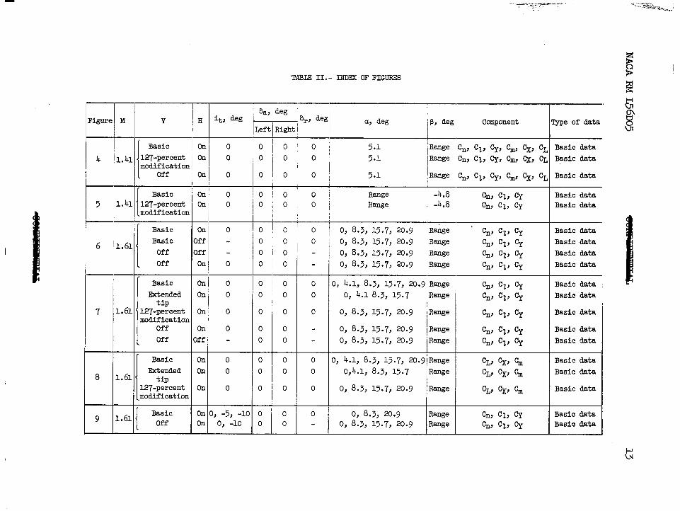
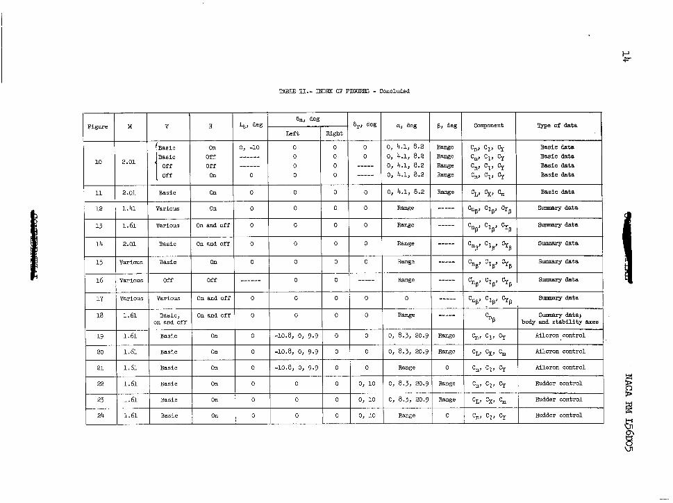
As seen in table II, the basic data are presented in figures 4 to 11; the summary data, in figures 12 to 18; the aileronYcontrol data, in figures 19 t0 2lj and the rudder-control data, in figures 22 to 24.
Static Stability Characteristics
Directional stability.- The directional stability Cn P
for the basic configuration decreases progressively both with increasing angle of attack and increasing Mach number until regions of undesirably low stability are encountered (see fig. 15). The directional characteristics for the tail- off configuration (fig. 16) are essentially invariant with Mach number and angle of attack and indicate a relatively large unstable moment. This large unstable moment results primarily from the large fuselage and the far-rearward moment center. The far-rearward moment center also results in a short tail moment arm and, hence, lessens the ability of the verti- cal tail to provide a stabilizing moment. Consequently, the condition exists where a large percentage of the tail contribution is consumed in overcoming the instability of the wing-body combination and relatively little tail effectiveness is available to provide a stability margin. Under such conditions, factors that affect the tail contribution, even to a slight degree, begin to assume greater importance. For example, r; the rapid decrease in Cn P
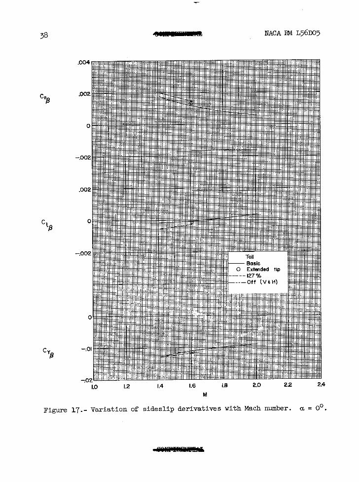
with increasing Mach number for the complete configuration is a direct result of the decrease to be expected in the vertical-tail lift-curve slope. In addition, as pointed out in'refer-
\i 3- d i ,I , L NACA RM ~561105 7
ence 2, the losses in tail contribution resulting from aeroelasticity might be significant for a full-scale airplane.
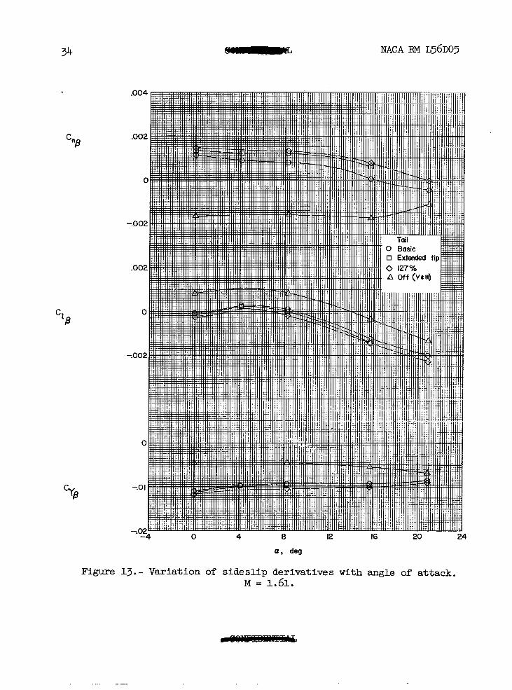
Increasing the tail contribution through increases in the tail area and aspect ratio, although having little effect on the variations of CnP with Mach number or angle of attack, does increase the'magnitude of CnD in such a way that the imminence of directional instability is delayed to higher angles of attack or to high Mach numbers. (See figs. 12, 13, and 17.)
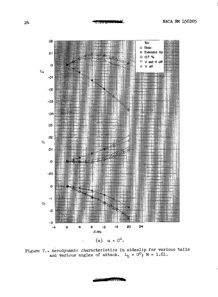
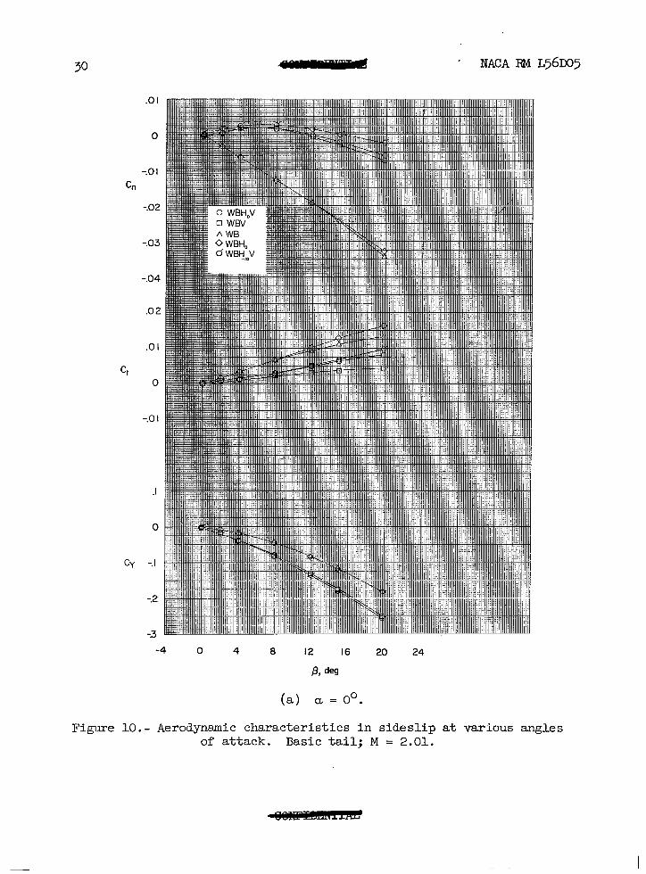
The variation of Cn with p for the complete model is rather nonlinear and does, in fact, indicate a reversal in direction which results in the occurrence of unstable yawing moments (fig. 7, for example). This trend is influenced to some extent by the increasing instability of the wing-body conibination and by a nonlinear vertical-tail contribution, and occurs even though the tail contribution continues to increase with increasing sideslip. Increasing the tail size does not remove this non- linear variation of C, with p but does delay the occurrence of the unstable yawing moments to higher angles of sideslip.
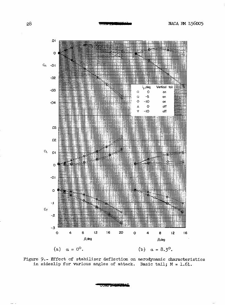
The presence of the horizontal tail provides a slight increase in the directional stability at a = 0' either with or without the vertical tail (figs. 6 and lo), but at higher angles of attack this effect reverses. Negative deflections of the horizontal tail provided an increase in the directional stability for the basic configuration at M = 1.61 (fig. p), apparently because of a transmittal of positive pressures from the upper surface of the horizontal tail to the windward side of the body and vertical tail. The effect of tail deflection is evident at M = 2.01 (fig. 10) but to a lesser degree since a smaller portion of the body and vertical tail are influenced by the flow field of the horizontal tail as the Mach number increases.
Results from other investigations involving configurations having high horizontal tails (ref. 3, for exsmple) indicate an opposite effect in that negative deflections of the horizontal tail cause a decrease in the directional stability.
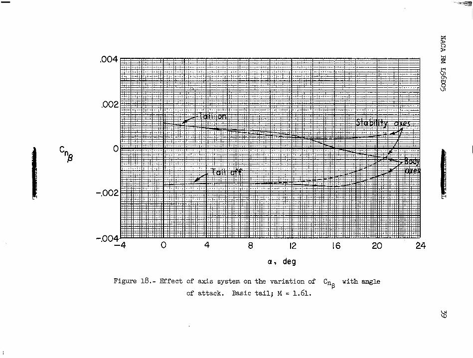
An interesting feature concerning the effects of the axis system on the interpretation of the data is illustrated in figure 18 where the variation of C
33 with a for the basic configuration at M = 1.61 is
presented for both the stability and the body axis systems. The results computed for the stability axis system indicate less deterioration of directional stability with increasing angle of attack and, in fact, do not indicate any directional instability for the tail-on case, whereas the results computed for the body axis system indicate directional insta- bility above a = 16O. This effect results from the transfer of rolling
8 NACA RM ~561105
moment into yawing moment for the stability axis system and can cause an a-ppreciable difference in C,
P at the higher angles of attack if the
rolling moments are large and the yawing moments are small. Thus, it is possible that some configuration changes that have a large effect on roll but little effecton yaw (such as wing dihedral) may, if computed for a stability axis system, show an effect on yaw.
Effective dihedral.- The variation of CZR with a for the basic
configuration is particularly nonlinear at Mach numbers of 1.41 and 1.61 (fig. 15): it varies from small negative values to small positive values at low angles of attack and increases to relatively large negative values at higher angles of attack. The results at M = 2.01 are for only a limited angle-of-attack range up to about 8 ', but within this range the variation of C2 with a is fairly linear.
P
For Mach numbers of 1.41 and 1.61, the variation of C2 with a P
at low angles of attack is generally positive either with or without the vertical tail (figs. 15 and 16); whereas for M = 2.01, the variation is negative. This trend toward negative variations of C2 with a for
P increasing Mach number is in general agreement with the linear-theory prediction for swept wings having supersonic leading edges (ref. 4).
The presence of the vertical tail, of course, provides a negative increment of C2
P that progressively increases as the tail size increases
and progressively decreases as the Mach number increases (fig. 17).
Effects of sideslip on longitudinal characteristics.- The lift, longiGZina1 force, and pitching moment vary only slightly with angle of sideslip for angles of attack up to about 8O (figs. 4, 8, and 11). At a = 15.7O and 20.p" (fig. S), however, a rapid positive increase of pitching moment with increasing sideslip indicates the possibility of cross coupling of the lateral, directional, and longitudinal motions. This cross-coupling tendency, combined with the greatly reduced direc- tional stability, might be the source of undesirable stability character- istics at the high angles of attack.
Lateral and Directional Control
Aileron characteristics.- The effects of aileron deflection on the lateral aerodynamic characteristics at M = 1.61 for the basic config- uration are presented in figure lg. The aileron remains effective in producing roll throughout the angle-of-attack and angle-of-sideslip
y NACA RM ~56~05 .- 9
ranges investigated. The results at a = O" indicate that deflection of the left aileron provides larger increments of rolling moment and smaller increments of yawing moment at positive sideslip angles than at negative sideslip angles. This probably occurs because the flow over the left wing tends to become more subsonic at positive sideslip angles and less subsonic at negative sideslip angles. These increments of rolling and yawing moments may also be associated with interference effects at the tail; however, no aileron deflection tests were made with the tails removed.
Although the linearity of rolling moment with aileron deflection was not determined for deflections above about loo, it appears that sufficient rolling power would be available to neutralize the maximum rolling moments encountered throughout the a and p ranges investi- gated with the possible exception of some combinations of a and p above a = 12O where C2
P becomes large (fig. 15).
The aileron effectiveness at j3 = 0' appears to increase slightly with increasing angle of attack (fig. 2l).
Upward deflections of the left aileron caused a negative yawing- moment increment at low angles of attack, whereas downward deflections caused negative yawing-moment increments at high angles of attack. Although these increments were small, they may, under the conditions of initially low directional stability and for greater aileron deflections, assume greater importance.
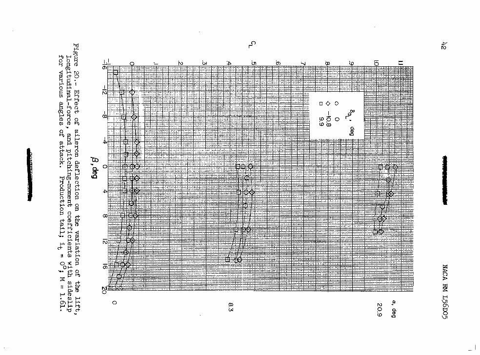
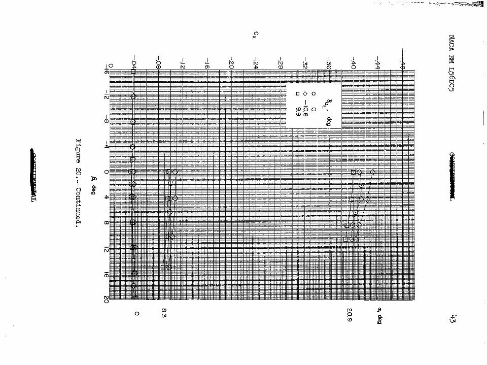
Deflection of the aileron does not appear to alter significantly the variation of CL, Cx, and Cm with p for angles of attack of 0' and 8.3O (fig. 20). At a= 20.9', negative deflection of one aileron appears to result in a more rapid increase of Cm with p than for zero deflection. However, opposite deflection of the other aileron should reduce this effect. As expected, deflection of the left aileron produces slightly greater increments of lift and pitching moment at positive sideslip angles than at negative sideslip angles. The differ- ences in drag increments due to aileron deflection at positive and neg- ative sideslip angles (a = O") were small.
Rudder characteristics.- A rudder deflection of loo for the basic configuration at M = 1.61. produces an essentially constant increment Of Cl-0 Cl, and CY throughout the angle-of-attack and sideslip ranges (figs. 22 and 24). At an angle of attack of O", a rudder deflec- tion of loo provides a trimmed sideslip angle of 2O. The trimmed side- slip angles increase with increasing angle of attack as the directional stability decreases until the trimmed angles would become infinite and then reverse in sign as the configuration becomes directionally unstable.
10 NACA RM ~56~05
It,is apparent that, because of the nonlinear variation of Cn with B, large deflections of the rudder might increase the tendency toward yawing divergence.
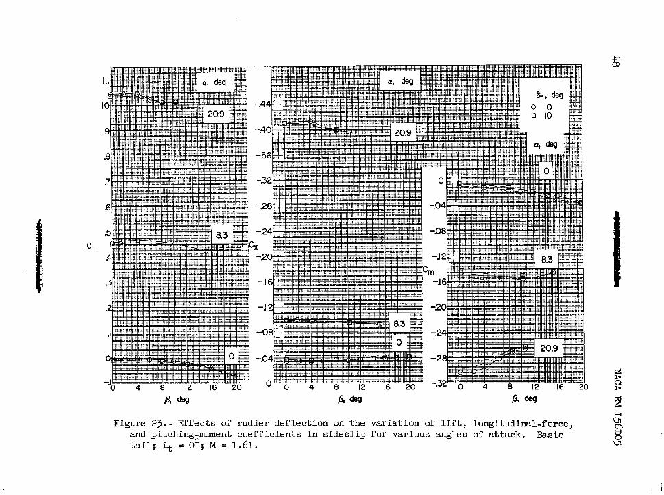
A rudder deflection of loo resulted in small decreases in lift and slight positive increases in pitching moments for all angles of attack (fig. 23).
CONCLUSIONS
An investigation has been made in the Langley 4- by k-foot super- sonic pressure tunnel at Mach numbers of 1.41, 1.61, and 2.01to deter- mine the static lateral stability and control characteristics of a model of a 45O swept-wing fighter airplane equipped with various vertical tails. The results of the investigation indicated the following conclusions:
1. Because of the loss in vertical-tail lift-curve slope and because of the magnitude of the unstable wing-body moment, the directional sta- bility derivative Cn
P for the complete configuration progressively
decreased with increasing Mach number and increasing angle of attack until regions of directional instability occurred.
2. Increasing the size of the vertical tail provided positive increases in C, so that the onset of directional instability was
P delayed to higher Mach numbers or higher angles of attack.
3. The lateral control provided by the ailerons and the directional control provided by the rudder at a Mach number of 1.61 were essentially constant throughout the angle-of-attack and sideslip ranges.
Langley Aeronautical Laboratory, National Advisory Colrrmittee for Aeronautics,
Langley Field, Va., March 28, 1956.
NACA RM ~56~05 11
1. Driver, Cornelius, and Foster, Gerald V.: Static Longitudinal Sta- bility and Control Characteristics of a Model of a 45O Swept-Wing Fighter Airplane at Mach Numbers of 1.41, 1.61, and 2.01. NACA RM ~56~04, 1956.
2. Drake, Hubert M., Finch, Thomas W., and Peele, James R.: Flight Measurements of Directional Stability to a Mach Number of 1.48 for an Airplane Tested With Three Different Vertical Tail Configura- tions. NACA RM H55G26, 1955.
3. Robinson, Ross B.: Longitudinal Characteristics of an Unswept-Wing Fighter-Type Model With External Stores at a Mach Number of 1.82 and Some Effects of Horizontal-Tail and Yaw-Damper Deflection on the Sideslip Derivatives. NACA RM ~55~26, 1956.
4. Jones, Arthur L., Sprieter, John R., and Alksne, Alberta: The Rolling Moment Due to Sideslip of Triangular, Trapezoid, and Related Plan Forms in Supersonic Flow. NACA TN 1700, 1948.
Planform Area, sq ft Aspect ratio ---- - Basic -- zxe+ded tip
0.167 0 ::E
I8 1145
Note:
lir Areas and aspect ratios are for panel outboard of
le A-A for the 127% tail and line B-B for the other tails.
rea: 0.0308 sq ft (all tail.$ Ba: .00241 sq ft 127 %
DO155 sq ft Basic and ext. tip
,=&in:{ 218 " j
c/4, prod. and ext. tip
-Fuselaae ref. line x
Figure 3.- Details of vertical tails.
i v* ‘i 1 f ;I r.. i:’
NACA FIM ~56~05
Cn
CY
02
01
0
-.o I
-02
703
-04
02
01
0
-.o I
.I
0
-.I
-.2
-.3 -12 -8 -4 0 4 8 12 I6 20
P/W
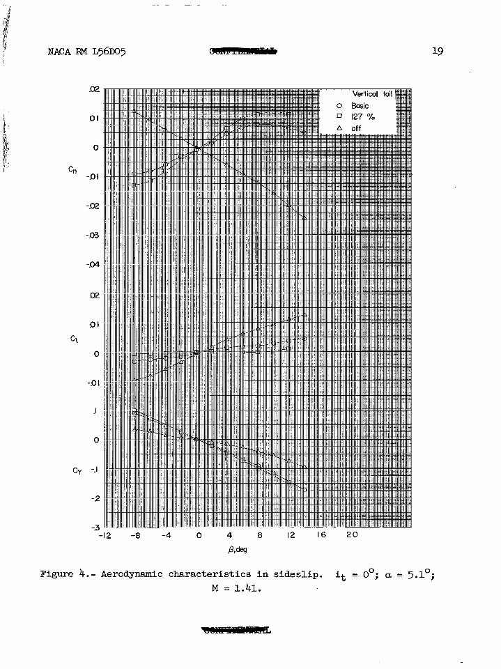
Figure 4.- Aerodynamic characteristics in sideslip. it = 0'; a = >.l"; M = 1.41.
NACA F&I ~56~05
cn
0
-.o I
-.02
02
al
c, 0
-.o I
CY
.I
0
-.I -16 -12 -8 -4 0 4 8 I2 I6 20 24
a, deg
Figure 5.- Effect of angle of attack on lateral stability characteristics. M= 1.41.
22 NACA I34 ~56~05
C”
c,
CY
.o I
0
-01
-.02
703
704
.03
02
01
0
-0 I
0
-.I
-.2
-.3 8 I2 I6 20 0 4 8 I2 I6
P, deg P,&s
(4 a = o”. (b) a = 8.3'.
Figure 6.- Effect of component parts on aerodynamic characteristics in sideslip for various angles of attack. Basic tail; it = 0'; M = 1.61.
NACA RM ~561x15
c,
c,
CY
I)I
0
-.o I
-.02
703
.o I
0
-.Ol
-.02
-.03
0
-.I
-.2
-.3 0 4
P, feg I2 I6 0 4 8 I2 I6
P, deg
(c) a = 15.7O. (d) a = 20.9’.
23
Figure 6 .- Concluded.
24
Cn
CY
02
I)I
0
-.o I
-02
703
-.04
.m
02
01
0
-.o I
0
-.I
-.2
-3
NACA F&I ~56~05
-4 0 4 8 I2 16 20 24
P&g
(4 a = o”.
Figure 7.- A&odynamic characteristics in sideslip for various tails and various angles of attack. it = O"; M = 1.61.
NACA RM ~56105
Cn -.o I
-02
DI
c\ 0
70 I
CY
0 4 8 I2 I6 0 4 8 I2 I6
P&g P&j
(b) a, = 4.1°. (4 a = 8.3O.
25
Figure 7. - Continued.
26
0
Cn -.o I
-02
-.03
0
-.o I
Cl -.02
703
-.04
0
31
CY
-.2
-3
NACA RM ~56~05
0 4 8 I2 I6 0 4 8 I2 I6
Pdes PANI
(d) a = 15.7O. (e) a = 20.9'.
Figure 7 .- Concluded.
Figure 8.- Variation of lift, longitudinal-force, and pitching-moment coefficients with angle of sideslip for various angles of attack. M = 1.61.
Y
28
01
0
G-l 701
-.02
-.03
-04
.03
02
cl .Ol
0
-.Ol
0
-.I
CY
-.2
Figure g.- Effect of stabilizer deflection on aerodynamic characteristics in sideslip for various angles of attack. Basic tail; M = 1.61.
NACA RM ~56~05
0 4 8 12 I6 20 0 4 8 I2 I6
P>cM wdes
(4 a = 0’. b) CL = 8.3O.
- n V P II
G ;
0
-a- V
9 9 ,o
0 8 ‘i .b
0 ‘0 - .b 0 .O -
0
P
$a
Iii
a,
0
P
g co
i3
30
Cn
Cl
CY
I NACA FiM ~56~05
.Ol
0
-.Oi
-.02
-.03
-.04
.02
.Ol
0
-.o I
0
-.I
-.2
-.3 -4 0 4 8 I2 16 20 24
P, deg
(a> a = o”.
Figure lO.- Aerodynamic characteristics in sideslip at various angles of attack. Basic tail; M = 2.01.
NACA FM ~561x15
Cn
Cl
CY
.Ol
0
-.o I
-.02
-.03
.Ol
0
-.o I
.I
0
-.I
-.2
-.3
0 4 8 I2 I6 0 4 8 I2 I6 P, deg B,deg
b) a = 4.10. (4 a = 8.2O.
Figure lo.- Concluded.
32 NACA RM ~56~05
8.2
8.2
8.2
0
Figure ll.- Variation of lift, longitudinal-force, and pitching-moment coefficients with sideslip for various angles of attack. model; basic tail; i+, = 0'; M = 2.01.
Complete
NACA RM ~56~05
- Basic
-- 127 %
A off
33
F i ! ‘. I,:,’ I’ i’: % I
= ,deg
Figure1 .2.- Variation of sideslip derivatives with angle of attack. M = 1.41; horizontal tail on.
34 NACA RM ~56~05
a, deg
Figure 13.- Variation of sideslip derivatives with angle of attack. M= 1.61.
NACA F&I ~56x15 35
-4 0 4 8 I2 16 20 24
a, deg
Figure 14.- Variation of sideslip derivatives with angle of attack. Basic tail; M = 2.01.
36
CY B
NACA FW ~56~05
-4 0 4 8 I2 I6 20 24
Q, deg
Figure 15.- Variation of sideslip deyivatives with angle of attack for various Mach numbers. Basic tail; horizontal tail on.
.~:y--;-- ./ >_, _
I ’ I
I& iP FDdR, Ln l P-
fDa
$g
XG
:pl
F8
E
c”
%
P
FS
2”
0”s
j;:
‘B
gp
L
Y
Ro
” $
b
F51
z
38
Cn B
NACA F&l ~56~05
Figure 17.- Variation of sideslip derivatives with Mach number. a. = O".
M
.004
.002
0
-.002
-.004 -4
Figure 18.- Effect of axis system on the variation of Cn P
with angle of attack. Basic tail; M = 1.61.
8 12 16 20 24
40 NACA RM ~56~05
Cn
C\
CY
-I 6 -12 -8 -4 0 4 8 12 16 20
Pdes
(4 a = o”. Figure lg.- Effect of aileron deflection on aerodynamic characteristics
in sideslip at various angles of attack. Basic tail; M = 1.61.
NACA RM ~56~05
Cn
0
-.I CY
-2
4 8 12 16 0 4 8 12 16
P/M Pdeg
(b) a = 8.3O. (4 a = 20.90.
Figure lg.- Concluded.
E% 2 ;Kt
d-0 Y 6 * Pa I OP
WJ
Kd! (TcOd
FXO cn 2 Y
% SE
tYz
z-%X
C-P
l Ek
‘d&i r
nl%
; I ;
G-0
kg
cl-0
E.2
kT
P I-‘* 4
-* 0
8
P K P.
c t 3%
” m 0”
“OS. v
-0 d-0
P+
II ;g
PO
b,cE
5.g: b
0 .P w
. , -. ,- - $--&+A+,~ --
44 NACA RM ~56x15
Figure 20.- Concluded.
a
a
2c
1 WI
0
.3
NACA RM ~56~05
Cn
45
Figure 2l.- Effects of angle of attack on a%leron-control characteristics. Basic tail; p = 0'; M = 1.61.
46
Fia Ire 22.- Effects of rudder deflection on aerodynamic characteristics in sideslip at various angles of attack. Basic tail; M = 1.61.
Cn
01
0
-.o I
0
NACA FiM ~56~05
C,
CY
0
-.I
-.2
-3
02
01
0
-.o I
-4 0 4 8 I2 I6 20 24
P,deg
(4 a = 0’.
NACA FM ~56~05
Cll
Cl
CY
DI
-0.
-.o I
0
-.o I
-02
-.03
0
-.I
-.2
-3 0 4 8 I2 I6 0 4 8 I2 I6
P, dq P,deg
(b) a = 8.3O. (4 a = 20.9O.
Figure 22.- Concluded.
Figure 23.- Effects of rudder deflection on the variation of lift, longitudinal-force, and pitcbingEmoment coefficients in sideslip for various angles of attack. l&sic tail; it = 0 ; M = 1.61.
-.
NACA RM ~561x35 49
Cn
CY
Figure 24. = ,deg
,- Efects of angle of attack on rudder-control characteristics. Basic tail; p = O"j M = 1.61.