High-speed machining technology is one of the four modern advanced manufacturing technologies, which has the main features of high cutting speed, high feed speed, and high machining precision. It is one of the high-tech technologies that leads to second manufacturing technology revolutionary leap [1]. High-speed motorized spindle is one of the core components to achieve high-speed machining, and equipped at most high-speed machine tools [2]. Shaft is the main rotation part of the motorized spindle and the manufacturing precision of the shaft will directly affect the spindle ultimate precision. The requirements of geometric tolerances and dimensional accuracy of finished shaft are very high. This paper designed a motorized spindle for high-speed machining center. The shaft structure was designed as an elongated hollow shaft, and the broach system was installed inside. It used separate structure, and the front end of the shaft separated from the rest of the shaft, as shown in Fig. 1. During operation, the shaft will withstand stress and centrifugal force and other cutting complex stress, and has high assembly accuracy requirements with other multiple components, therefore its processing technology and precision are the key issues.
(a)Integrated shaft(b)Assembly drawing of shaft and front end
Fig.1 Relation of shaft and front end
Firstly, this paper did the structural analysis of shaft, considering the dimension, position accuracy requirements, and assembly requirements with other parts. Secondly, it studies the manufacturing processes of shaft. Then it designed a feasible and efficient processing scheme, and through the actual shaft processing to verify the feasibility of the manufacturing processes.
II. SHAFT STRUCTURE ANALYSIS AND PROCESSING
PROBLEMS
The assembly schematic diagram of shaft with other parts is shown in Fig. 2, the shaft 1 is a hollow shaft and broach institutions with tool clamping function is installed inside. The shaft and the shaft front end 2 are connected by a bolt, to locate the tool installation. Between of them is the inner spacer 3, with several uniform arrangement threaded holes inside, to do the dynamic balance adjustment during motorized spindle assembly. Next part is the front bearing 4 that interference fit with the shaft. Central part of shaft is connected with motor rotor 5 through the rotor heating or shaft cooling process, and the rear end is the back bearing 6. As there are many high precision assembly requirements on the shaft and other parts, the processes need to consider the shaft dimensional and geometric tolerance requirements, and also the assembly requirements of shaft and other parts. So it is necessary to adjust the manufacturing processes to improve the machining accuracy and surface quality of the shaft.
Fig. 2 Assembly schematic diagram of shaft with other parts(1-shaft, 2-
shaft front end, 3-front end inner spacer, 4-front bearing, 5-motor rotor, 6-
back bearing)
During the high-speed machining process, the broach institution directly delivers the complex cutting stress to the shaft. In order to reduce the shaft deformation, extend service life time, and ensure the machine's high precision, the shaft blank is required to do swaging process and grain refinement, to make the material structure more closely and improve the material properties. During the machining process, it necessary to choose the right heat treatment process, and
International Workshop of Advanced Manufacturing and Automation (IWAMA 2016)
optimize the materials, to improve the mechanical properties of strength and wear resistance, etc.
III. MANUFACTURING PROCESSES ANALYSIS AND DESIGN
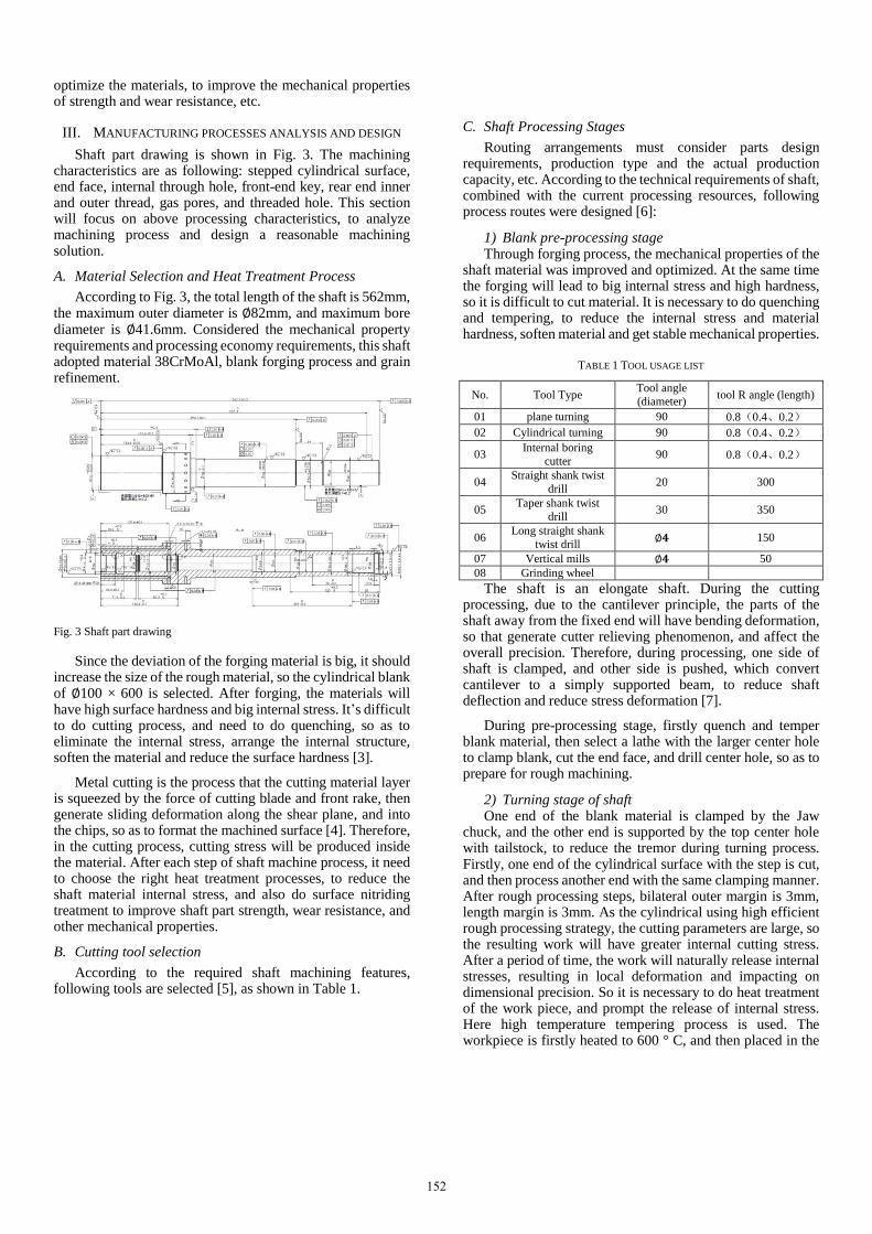
Shaft part drawing is shown in Fig. 3. The machining characteristics are as following: stepped cylindrical surface, end face, internal through hole, front-end key, rear end inner and outer thread, gas pores, and threaded hole. This section will focus on above processing characteristics, to analyze machining process and design a reasonable machining solution.
A. Material Selection and Heat Treatment Process
According to Fig. 3, the total length of the shaft is 562mm, the maximum outer diameter is ∅82mm, and maximum bore diameter is ∅41.6mm. Considered the mechanical property requirements and processing economy requirements, this shaft adopted material 38CrMoAl, blank forging process and grain refinement.
Fig. 3 Shaft part drawing
Since the deviation of the forging material is big, it should increase the size of the rough material, so the cylindrical blank of ∅100 × 600 is selected. After forging, the materials will have high surface hardness and big internal stress. It’s difficult to do cutting process, and need to do quenching, so as to eliminate the internal stress, arrange the internal structure, soften the material and reduce the surface hardness [3].
Metal cutting is the process that the cutting material layer is squeezed by the force of cutting blade and front rake, then generate sliding deformation along the shear plane, and into the chips, so as to format the machined surface [4]. Therefore, in the cutting process, cutting stress will be produced inside the material. After each step of shaft machine process, it need to choose the right heat treatment processes, to reduce the shaft material internal stress, and also do surface nitriding treatment to improve shaft part strength, wear resistance, and other mechanical properties.
B. Cutting tool selection
According to the required shaft machining features, following tools are selected [5], as shown in Table 1.
C. Shaft Processing Stages
Routing arrangements must consider parts design requirements, production type and the actual production capacity, etc. According to the technical requirements of shaft, combined with the current processing resources, following process routes were designed [6]:
1) Blank pre-processing stage Through forging process, the mechanical properties of the
shaft material was improved and optimized. At the same time the forging will lead to big internal stress and high hardness, so it is difficult to cut material. It is necessary to do quenching and tempering, to reduce the internal stress and material hardness, soften material and get stable mechanical properties.
TABLE 1 TOOL USAGE LIST
No. Tool Type Tool angle
(diameter) tool R angle (length)
01 plane turning 90 0.8(0.4、0.2)
02 Cylindrical turning 90 0.8(0.4、0.2)
03 Internal boring
cutter 90 0.8(0.4、0.2)
04 Straight shank twist
drill 20 300
05 Taper shank twist
drill 30 350
06 Long straight shank
twist drill ∅𝟒 150
07 Vertical mills ∅𝟒 50
08 Grinding wheel
The shaft is an elongate shaft. During the cutting processing, due to the cantilever principle, the parts of the shaft away from the fixed end will have bending deformation, so that generate cutter relieving phenomenon, and affect the overall precision. Therefore, during processing, one side of shaft is clamped, and other side is pushed, which convert cantilever to a simply supported beam, to reduce shaft deflection and reduce stress deformation [7].
During pre-processing stage, firstly quench and temper blank material, then select a lathe with the larger center hole to clamp blank, cut the end face, and drill center hole, so as to prepare for rough machining.
2) Turning stage of shaft One end of the blank material is clamped by the Jaw
chuck, and the other end is supported by the top center hole with tailstock, to reduce the tremor during turning process. Firstly, one end of the cylindrical surface with the step is cut, and then process another end with the same clamping manner. After rough processing steps, bilateral outer margin is 3mm, length margin is 3mm. As the cylindrical using high efficient rough processing strategy, the cutting parameters are large, so the resulting work will have greater internal cutting stress. After a period of time, the work will naturally release internal stresses, resulting in local deformation and impacting on dimensional precision. So it is necessary to do heat treatment of the work piece, and prompt the release of internal stress. Here high temperature tempering process is used. The workpiece is firstly heated to 600 ° C, and then placed in the
152
air naturally cooled down to room temperature. After the process the workpiece material can be more uniform, and mechanical properties of the workpiece is improved.
3) Hole drilling and boring stage Since the shaft is an elongated shaft, the axial dimension
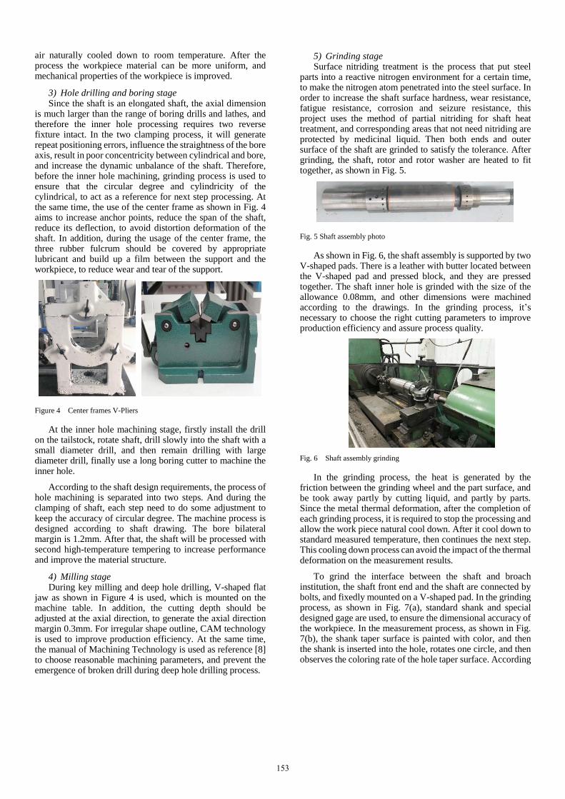
is much larger than the range of boring drills and lathes, and therefore the inner hole processing requires two reverse fixture intact. In the two clamping process, it will generate repeat positioning errors, influence the straightness of the bore axis, result in poor concentricity between cylindrical and bore, and increase the dynamic unbalance of the shaft. Therefore, before the inner hole machining, grinding process is used to ensure that the circular degree and cylindricity of the cylindrical, to act as a reference for next step processing. At the same time, the use of the center frame as shown in Fig. 4 aims to increase anchor points, reduce the span of the shaft, reduce its deflection, to avoid distortion deformation of the shaft. In addition, during the usage of the center frame, the three rubber fulcrum should be covered by appropriate lubricant and build up a film between the support and the workpiece, to reduce wear and tear of the support.
Figure 4 Center frames V-Pliers
At the inner hole machining stage, firstly install the drill on the tailstock, rotate shaft, drill slowly into the shaft with a small diameter drill, and then remain drilling with large diameter drill, finally use a long boring cutter to machine the inner hole.
According to the shaft design requirements, the process of hole machining is separated into two steps. And during the clamping of shaft, each step need to do some adjustment to keep the accuracy of circular degree. The machine process is designed according to shaft drawing. The bore bilateral margin is 1.2mm. After that, the shaft will be processed with second high-temperature tempering to increase performance and improve the material structure.
4) Milling stage During key milling and deep hole drilling, V-shaped flat
jaw as shown in Figure 4 is used, which is mounted on the machine table. In addition, the cutting depth should be adjusted at the axial direction, to generate the axial direction margin 0.3mm. For irregular shape outline, CAM technology is used to improve production efficiency. At the same time, the manual of Machining Technology is used as reference [8] to choose reasonable machining parameters, and prevent the emergence of broken drill during deep hole drilling process.
5) Grinding stage Surface nitriding treatment is the process that put steel
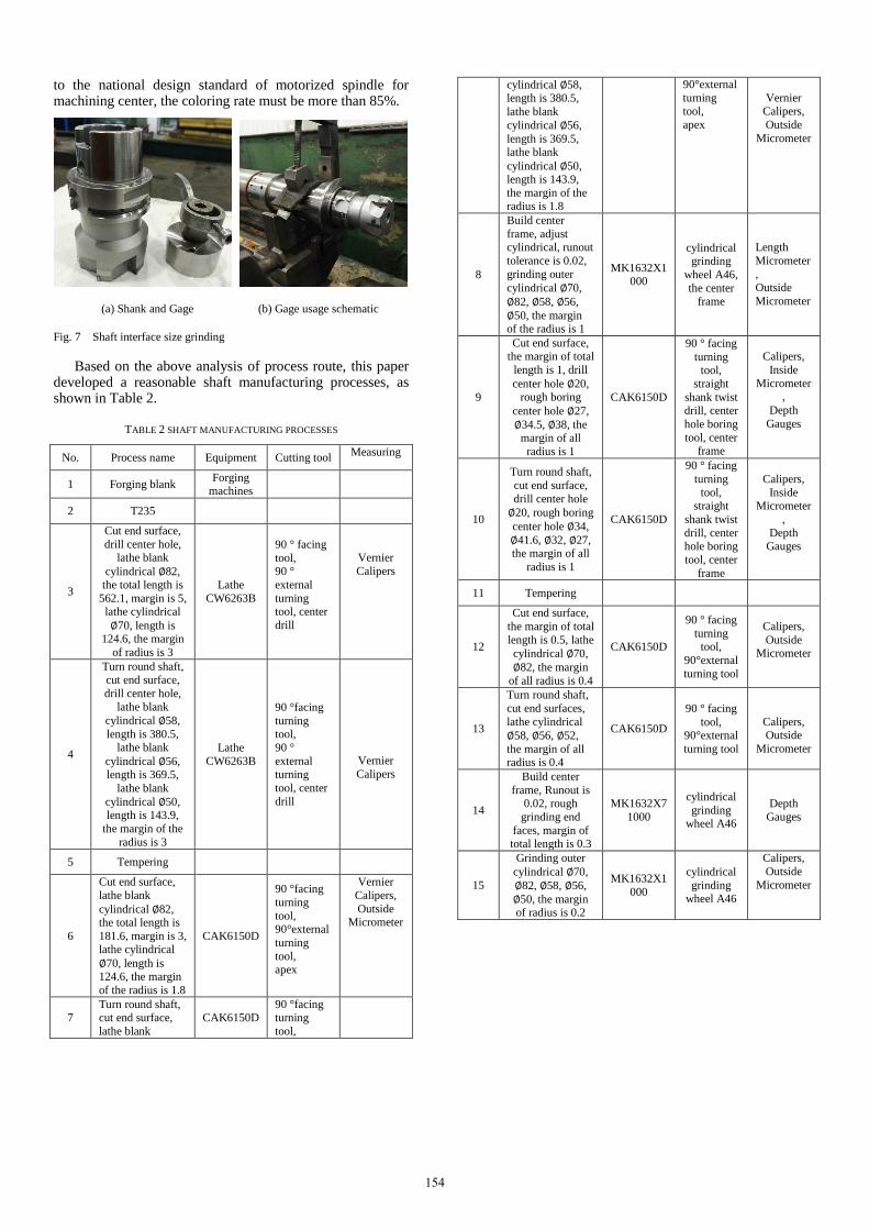
parts into a reactive nitrogen environment for a certain time, to make the nitrogen atom penetrated into the steel surface. In order to increase the shaft surface hardness, wear resistance, fatigue resistance, corrosion and seizure resistance, this project uses the method of partial nitriding for shaft heat treatment, and corresponding areas that not need nitriding are protected by medicinal liquid. Then both ends and outer surface of the shaft are grinded to satisfy the tolerance. After grinding, the shaft, rotor and rotor washer are heated to fit together, as shown in Fig. 5.
Fig. 5 Shaft assembly photo
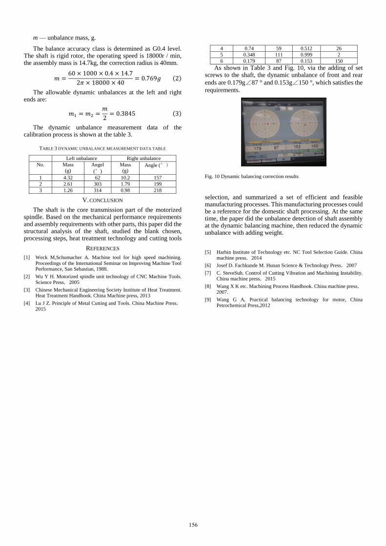
As shown in Fig. 6, the shaft assembly is supported by two V-shaped pads. There is a leather with butter located between the V-shaped pad and pressed block, and they are pressed together. The shaft inner hole is grinded with the size of the allowance 0.08mm, and other dimensions were machined according to the drawings. In the grinding process, it’s necessary to choose the right cutting parameters to improve production efficiency and assure process quality.
Fig. 6 Shaft assembly grinding
In the grinding process, the heat is generated by the friction between the grinding wheel and the part surface, and be took away partly by cutting liquid, and partly by parts. Since the metal thermal deformation, after the completion of each grinding process, it is required to stop the processing and allow the work piece natural cool down. After it cool down to standard measured temperature, then continues the next step. This cooling down process can avoid the impact of the thermal deformation on the measurement results.
To grind the interface between the shaft and broach institution, the shaft front end and the shaft are connected by bolts, and fixedly mounted on a V-shaped pad. In the grinding process, as shown in Fig. 7(a), standard shank and special designed gage are used, to ensure the dimensional accuracy of the workpiece. In the measurement process, as shown in Fig. 7(b), the shank taper surface is painted with color, and then the shank is inserted into the hole, rotates one circle, and then observes the coloring rate of the hole taper surface. According
153
to the national design standard of motorized spindle for machining center, the coloring rate must be more than 85%.
(a) Shank and Gage (b) Gage usage schematic
Fig. 7 Shaft interface size grinding
Based on the above analysis of process route, this paper developed a reasonable shaft manufacturing processes, as shown in Table 2.
TABLE 2 SHAFT MANUFACTURING PROCESSES
No. Process name Equipment Cutting tool Measuring
1 Forging blank Forging
machines
2 T235
3
Cut end surface,
drill center hole, lathe blank
cylindrical ∅82, the total length is
562.1, margin is 5, lathe cylindrical
∅70, length is 124.6, the margin
of radius is 3
Lathe
CW6263B
90 ° facing
tool, 90 °
external
turning tool, center
drill
Vernier
Calipers
4
Turn round shaft,
cut end surface,
drill center hole,
lathe blank
cylindrical ∅58,
length is 380.5, lathe blank
cylindrical ∅56, length is 369.5,
lathe blank
cylindrical ∅50, length is 143.9,
the margin of the
radius is 3
Lathe
CW6263B
90 °facing
turning tool,
90 °
external turning
tool, center
drill
Vernier
Calipers
5 Tempering
6
Cut end surface,
lathe blank
cylindrical ∅82, the total length is
181.6, margin is 3,
lathe cylindrical
∅70, length is 124.6, the margin
of the radius is 1.8
CAK6150D
90 °facing
turning
tool, 90°external
turning
tool, apex
Vernier
Calipers,
Outside Micrometer
7 Turn round shaft, cut end surface,
lathe blank
CAK6150D 90 °facing turning
tool,
cylindrical ∅58, length is 380.5,
lathe blank
cylindrical ∅56,
length is 369.5, lathe blank
cylindrical ∅50, length is 143.9,
the margin of the radius is 1.8
90°external
turning tool,
apex
Vernier Calipers,
Outside
Micrometer
8
Build center
frame, adjust cylindrical, runout
tolerance is 0.02,
grinding outer
cylindrical ∅70,
∅82, ∅58, ∅56,
∅50, the margin of the radius is 1
MK1632X1000
cylindrical grinding
wheel A46,
the center frame
Length
Micrometer
, Outside
Micrometer
9
Cut end surface, the margin of total
length is 1, drill
center hole ∅20, rough boring
center hole ∅27,
∅34.5, ∅38, the margin of all
radius is 1
CAK6150D
90 ° facing
turning tool,
straight
shank twist
drill, center
hole boring
tool, center frame
Calipers,
Inside
Micrometer,
Depth
Gauges
10
Turn round shaft,
cut end surface,
drill center hole
∅20, rough boring
center hole ∅34,
∅41.6, ∅32, ∅27, the margin of all
radius is 1
CAK6150D
90 ° facing
turning
tool, straight
shank twist
drill, center hole boring
tool, center
frame
Calipers,
Inside Micrometer
,
Depth Gauges
11 Tempering
12
Cut end surface,
the margin of total
length is 0.5, lathe
cylindrical ∅70,
∅82, the margin
of all radius is 0.4
CAK6150D
90 ° facing
turning tool,
90°external
turning tool
Calipers,
Outside Micrometer
13
Turn round shaft,
cut end surfaces,
lathe cylindrical
∅58, ∅56, ∅52,
the margin of all radius is 0.4
CAK6150D
90 ° facing
tool, 90°external
turning tool
Calipers, Outside
Micrometer
14
Build center
frame, Runout is 0.02, rough
grinding end
faces, margin of total length is 0.3
MK1632X7
1000
cylindrical
grinding wheel A46
Depth
Gauges
15
Grinding outer
cylindrical ∅70,
∅82, ∅58, ∅56,
∅50, the margin of radius is 0.2
MK1632X1
000
cylindrical
grinding wheel A46
Calipers,
Outside
Micrometer
154
16
Cut end surface as the drawings,
boring internal
hole ∅27, ∅34.5,
∅38, margin of the radius is 0.2
CAK6150D
90 ° facing
tool, inner hole boring
tool
Calipers,
Inside Micrometer
,
Depth Gauges
17
Turn round shaft, cut end surface,
boring inner hole
∅34, ∅41.6, ∅32,
∅27, lathe inner and external
thread, the margin of the radius is 0.2
CAK6150D
90 ° facing
tool, inner
hole boring tool,
60 °
threading tool
Length Micrometer
,
Inside Micrometer
, Thread
Feeler
18 Tempering
19 Drill periphery
hole Hass VF-3
center drill,
twist drill, taps
Calipers
20 Mill key, drill
deep holes JE80S
vertical
mills, center drill,
twist drill
Calipers
21
Nitriding
treatment, protect threaded
hole and external
thread inside shaft with bolt and
bulkhead
22
Grinding end surface as
drawings,
grinding outer
cylindrical ∅70,
∅82, ∅58, ∅56,
∅50 as drawings
MK1632X1000
Cylindrical
grinding
wheel A46
Length Micrometer
,
Outside Micrometer
23
Build center
frame, runout is 0.01, grind all
inner hole as
requirements, enlarged view of
X segment,
margin is 0.1
MGA1432
X1500
Internal
Grinding
Wheel
WA46P
Length
Micrometer,
Inside
Micrometer,
Depth
Gauge
24
Interface with the
shaft front end
surface, grinding to the required
size 52js8
MGA1432
X1500
Inner radius
grinding
wheel WA46P
1: 10 Taper
Plug,
Shank, Gages
25 Comprehensive
examination
26
Clean, coated with
anti-rust oil,
storage
IV. SHAFT ASSEMBLY BALANCING TEST
For shaft parts, due to material uneven or blank defect, deviation generated by processing and assembly, even there are possible asymmetric geometry at design stage, etc., so that during the rotation of the shaft, the centrifugal force generated by each tiny particle can’t balance each other, then cause vibration and noise effect. It will accelerate bearing wear and shorten the life of the machine. At severe cases it can cause
devastating accidents [9]. Therefore, balancing test for the shaft and its assembly must be carried out, to reach allowed equilibrium accuracy and limit the mechanical vibration amplitude within the permissible range.
Balancing machine of the shaft consists of two V-shaped support frame, the axial stopper mechanism, corresponding sensors and power system. The base is the marble structure. As shown in Fig. 8, the shaft is placed on the two V-shaped support frame, adjust the opening width of the V-shaped bracket, and use a dial gauge to detect the runout of the shaft. At the same time, to reduce the resonance effects, the diameter of shaft support should be different with herein V-plus opening width.
Fig. 8 Shaft balancing test
As shown Fig. 9, the balancing test of this project uses the supporting mode that two correction planes are placed on the middle of the supporting surface. Weight increasing is selected as calibration mode. The threaded hole of the shaft is screwed with a fastening screw to adjust dynamic unbalance, and the operating speed is chosen as 1200rpm according to spindle unit working speed. As shown in the Fig.9, dynamic
unbalance of the shaft assembly are as following: 4.32g∠62
° and 10.2g∠157 °.
Fig. 9 Balancing parameter setting and measurement
According to GB/T9239--2006 "Mechanical vibration steady state (rigid) rotor balancing quality requirements":
𝑚 =60 × 1000 × 𝐺𝑀
2𝜋𝑛𝑟 (1)
In the equation:
M — rotor mass, kg;
G — accuracy class selection;
R — correction radius, r/min;
N — workpiece operating speed, r/min;
155
m — unbalance mass, g.
The balance accuracy class is determined as G0.4 level. The shaft is rigid rotor, the operating speed is 18000r / min, the assembly mass is 14.7kg, the correction radius is 40mm.
𝑚 =60 × 1000 × 0.4 × 14.7
2𝜋 × 18000 × 40= 0.769𝑔 (2)
The allowable dynamic unbalances at the left and right ends are:
𝑚1 = 𝑚2 =𝑚
2= 0.3845 (3)
The dynamic unbalance measurement data of the calibration process is shown at the table 3.
TABLE 3 DYNAMIC UNBALANCE MEASUREMENT DATA TABLE
Left unbalance Right unbalance
No. Mass
(g)
Angel
(°)
Mass
(g) Angle (°)
1 4.32 62 10.2 157
2 2.61 303 1.79 199
3 1.26 314 0.98 218
4 0.74 59 0.512 26
5 0.348 111 0.999 2
6 0.179 87 0.153 150
As shown in Table 3 and Fig. 10, via the adding of set screws to the shaft, the dynamic unbalance of front and rear
ends are 0.179g∠87 ° and 0.153g∠150 °, which satisfies the
requirements.
Fig. 10 Dynamic balancing correction results
V. CONCLUSION
The shaft is the core transmission part of the motorized spindle. Based on the mechanical performance requirements and assembly requirements with other parts, this paper did the structural analysis of the shaft, studied the blank chosen, processing steps, heat treatment technology and cutting tools
selection, and summarized a set of efficient and feasible manufacturing processes. This manufacturing processes could be a reference for the domestic shaft processing. At the same time, the paper did the unbalance detection of shaft assembly at the dynamic balancing machine, then reduced the dynamic unbalance with adding weight.
REFERENCES
[1] Weck M,Schumacher A. Machine tool for high speed machining. Proceedings of the International Seminar on Improving Machine Tool Performance, San Sebastian, 1988.
[2] Wu Y H. Motorized spindle unit technology of CNC Machine Tools. Science Press,2005
[3] Chinese Mechanical Engineering Society Institute of Heat Treatment. Heat Treatment Handbook. China Machine press, 2013
[4] Lu J Z. Principle of Metal Cutting and Tools. China Machine Press,2015
[5] Harbin Institute of Technology etc. NC Tool Selection Guide. China machine press,2014
[6] Josef D. Fachkunde M. Hunan Science & Technology Press,2007
[7] C. SteveSuh. Control of Cutting Vibration and Machining Instability. China machine press,2015
[8] Wang X K etc. Machining Process Handbook. China machine press,2007.
[9] Wang G A, Practical balancing technology for motor, China Petrochemical Press,2012