U.P.B. Sci. Bull., Series D, Vol. 82, Iss. 3, 2020 ISSN 1454-2358 RESEARCH ON THE OPTIMIZED CONTROL BY LOCAL LORENTZ FORCE TO ADJUST THE SUBMARINE VIBRATION IN THE SEAWATER Zongkai LIU 1,* , Fei ZHANG 2 This work different streamwise Lorentz forces around the certain parts of the submarine have been applied to suppress the vibration. The flow structure and the force variation of submarine are analyzed in the three local regions of submarine (A=1, A=2, A=3), where electromagnetic force (or Lorentz force) is applied. The results suggest that the vortices appear on the junction of the hemispherical fore- body and mid-body can be effectively suppressed when the (A=1) Lorentz force is applied. Applying Lorentz force on the top of fin (A=2) may effectively suppress the vortex shedding and the drag force waves reaches the most flat. Reduction of the submarine moment is most obvious when the Lorentz force action on the side surface of the fin (A=3). Therefore, intelligent utilization of Lorentz force in the boundary layer flow control of the fin may efficaciously suppress the formation of abnormal vortices and shedding, reduce flow noise and improve the stealth capability and the dynamic performance of submarines. Keywords: flow structure around submarine, Lorentz force control, optimized control, resistance reduction 1. Introduction The flow separation, boundary layer transition and vortex shedding will appear while submarines voyage at high speed under seawater. The frictional movement between the viscous seawater and the submarine’s surface causes turbulences along with several hydrodynamic noises. Hydrodynamic vibrations and noises are also known as the flow noises without considering any structural resonance induced by the flow fields and metal hulls. The complex fluid phenomena arouse the destabilization of the force and moment for the underwater submarine. Hydrodynamic noises are mainly generated from the destabilization’s transmission, which seriously affects the stealth capacity of the submarine. Many researchers have focused on the seawater flow field around submarines already. Chase et al. calculated the open water curves about E1619 submarine propeller and compared the simulation results with the experiments [1]. 1 Assistant Research Fellow, Zongkai Liu; College of Automation, Nanjing University of Science and Technology, Nanjing, China; e-mail: [email protected]2 Postgraduate Student, Fei Zhang; Science and Technology on Transient Physics Laboratory, Nanjing University of Science and Technology, Nanjing , China; ; e-mail:[email protected]* Corresponding author. E-mail: [email protected]
RESEARCH ON THE OPTIMIZED CONTROL BY LOCAL LORENTZ FORCE TO ADJUST THE SUBMARINE
VIBRATION IN THE SEAWATER
Zongkai LIU1,*, Fei ZHANG2 This work different streamwise Lorentz forces around the certain parts of the
submarine have been applied to suppress the vibration. The flow structure and the force variation of submarine are analyzed in the three local regions of submarine (A=1, A=2, A=3), where electromagnetic force (or Lorentz force) is applied. The results suggest that the vortices appear on the junction of the hemispherical fore-body and mid-body can be effectively suppressed when the (A=1) Lorentz force is applied. Applying Lorentz force on the top of fin (A=2) may effectively suppress the vortex shedding and the drag force waves reaches the most flat. Reduction of the submarine moment is most obvious when the Lorentz force action on the side surface of the fin (A=3). Therefore, intelligent utilization of Lorentz force in the boundary layer flow control of the fin may efficaciously suppress the formation of abnormal vortices and shedding, reduce flow noise and improve the stealth capability and the dynamic performance of submarines.
Keywords: flow structure around submarine, Lorentz force control, optimized control, resistance reduction
1. Introduction
The flow separation, boundary layer transition and vortex shedding will appear while submarines voyage at high speed under seawater. The frictional movement between the viscous seawater and the submarine’s surface causes turbulences along with several hydrodynamic noises. Hydrodynamic vibrations and noises are also known as the flow noises without considering any structural resonance induced by the flow fields and metal hulls. The complex fluid phenomena arouse the destabilization of the force and moment for the underwater submarine. Hydrodynamic noises are mainly generated from the destabilization’s transmission, which seriously affects the stealth capacity of the submarine.
Many researchers have focused on the seawater flow field around submarines already. Chase et al. calculated the open water curves about E1619 submarine propeller and compared the simulation results with the experiments [1].
1 Assistant Research Fellow, Zongkai Liu; College of Automation, Nanjing University of Science and Technology, Nanjing, China; e-mail: [email protected] 2 Postgraduate Student, Fei Zhang; Science and Technology on Transient Physics Laboratory, Nanjing University of Science and Technology, Nanjing , China; ; e-mail:[email protected] * Corresponding author. E-mail: [email protected]
52 Zongkai Liu, Fei Zhang
Shariati et al. demonstrated the drag force increased obviously for the existence of appendage structures [2]. Chen et al discussed the distribution of noise in the turbulent flows [3].
In summary, all the researches referring to the submarine aim to improve the navigation efficiency and its concealment performance. With the development of science and technology, the electromagnetic flow control is adopted in the relevant researches [4, 5]. Lorentz force is utilized to modify the boundary layer flow structure, which could even affect the whole flow field. For weak electrolyte solution such as the seawater, Lorentz force along the arrange direction of the electrodes and magnetic poles can be excited by the electromagnetic actuator mounted on the surface (Fig. 1). The streamwise Lorentz force could accelerate boundary layer flow field. Thus the purpose of suppression of flow separation, eliminating the vortex streets and reducing the drag could be achieved by applying different types of the Lorentz force [6-10].
Fig. 1 The electromagnetic actuator immersed in seawater
For high Reynolds number, the stealthy capability of submarine is destroyed owing to the noise generated from the flow separation, vortex shedding and the transition from laminar flow to turbulence and so on. In present work, streamwise Lorentz boundary layer control is adopted to reduce drag and body vibration.
2. Geometric model and numerical scheme
2.1 The simulation model
Fig. 2 shows the geometric characteristics of the submarine model and the Lorentz force action areas. A hemisphere, a cylindrical mid-body and a smoothly tapered after-body compose the submarine hull. An elliptical cylinder appends at 0.3 l from the leading point with the height of 0.06 l. The length of the three parts are 0.06 l, 0.69 l and 0.25 l (l is the length of the body, as the characteristic length in the calculation), respectively [11].
Research on the optimized control by local Lorentz force to adjust the submarine vibration in the seawater 53
The interaction parameter N=2∙ j0B0lρu∞
2 is the ratio of Lorentz force to the inertial fluid force, where j0 , B0 , ρ are the current density and magnetic field values at the electrode and magnet surface as well as the fluid density [12]. A is defined as the covering parameter, A=0 indicates that there is no Lorentz force on the body. As shown in Fig. 2 , A=1, A=2 and A=3 represent the Lorentz force is applied on the different positions of the body with the interaction parameter N = 1.5.
Fig. 2. Geometric characteristics of the submarine and the position for streamwise Lorentz force
control
As shown in Fig. 3, the computational domain is a 4l×2l×2l cuboid and the boundary conditions are indicated in this figure. The leading point of submarine is located at (-0.02 l, 0.5 l, 0), while the origin of the Cartesian coordinate located at 0.5 l downstream from the inlet.
Fig. 3. The computational boundary conditions for the submarine
2.2. Governing equations
In this paper, the governing equations with Lorentz force in non-dimensional form can be written as:
54 Zongkai Liu, Fei Zhang
∇⋅U=0 (1) ∂U∂t
+U⋅∇U=-∇p+ 1Re∇2U+NF (2)
∇×E=- ∂B∂t
(3) ∇×B=μ0J (4) ∇⋅B=0 (5) ∇⋅E= ρe
e0 (6)
where U=( u, v, w) is the velocity vector, p is the pressure, Re is the Reynolds number based on the length of the submarine, t is the time with no dimension; μ0, ρe , e0 are the magnetic permeability, the charge density and the electrical permeability, respectively [13].
Eq. (2) implies that the dimensionless Lorentz force, F, can be represented by the magnetic flux density vector, B, and the electrode current density vector, J:
F= 1j0B0
(J×B) (7)
J is given by Ohm’s law: J=σ(E+U×B) (8)
where σ denotes the electrical conductivity, E the electric field, and U is the fluid velocity [14].
In case of weakly conducting fluid (such as sea water), σ is small. The U×B term in the Eq. (8) can be ignored, compared with the electric field E. Thus, we finally obtain that the dimensionless Lorentz force, F, is written as follows:
F= σj0B0
(E×B) (9)
2.3 Spatial and temporal discretization
The domain is spatially discretized using cubic finite volumes organized hierarchically as an octree. The fundamental feature of the tree-type discretization is that each cell can be divided into eight subcells in three-dimension [15, 16]. The local vorticity magnitude is employed as a criterion to judge the mesh division dynamically and track the evolving turbulent wake (Fig. 4). The minimum grid size is l 29⁄ and the total grid number is approximately 2 million.
Research on the optimized control by local Lorentz force to adjust the submarine vibration in the seawater 55
A simple formula based on the local fluid parameters is used. A cell will be refined as
h|∇×U|max|U| >ε (10)
where h is the cell size and ε is a user-defined threshold which may be interpreted as the maximum angular deviation (caused by the local vorticity) of a particle traveling at speed max|U| across the cell [17]. The threshold ε in this paper is selected as 10-2.
The fractional-step projection method is used to implement temporal discretization. This projection method relies on the Hodge decomposition of the velocity field. Here, an exact projection for face-centered advection velocities is used, while an approximate projection of the cell-centred velocities is applied on the final projection. The multilevel Poisson solver that combines naturally with the octree spatial discretization is used. The advection terms are discretized using the robust second-order upwind scheme (Bell et al), thus, second-order convergence in space and time is achieved. The diffusion terms are discretized using the implicit Crank-Nicolson scheme [18, 19].
56 Zongkai Liu, Fei Zhang
2.4 Numerical validation
The algorithm used in this study is validated by the simulation of three-dimensional viscous flow past a circular cylinder performed at Reynolds number (based on the diameter of the cylinder D) 100. Periodic boundary condition is applied along the spanwise direction. No-slip boundary condition is used on the cylinder surface and the inlet boundary condition is free to flow. The outlet is set as the pressure boundary condition. The minimum mesh size is 10D/28, and the total number of grids is approximately up to 1 billion.
The drag force coefficient, lift force coefficient, and Strouhal number is defined as CD=2FD/�ρU∞
2 S� , CL=2FL/�ρU∞2 S� and St=fD/U∞, where FD, FL, f are
the drag, lift force per unit span, and vortex shedding frequency, respectively. S=D·H, where S is the lateral area of the cylinder, H is the height of cylinder.
As shown in Table 1, the force coefficients of the fluid flow around cylinder are in good agreement with available numerical and experimental results. This numerical method has also been verified based on four different grids level number. My previous study paper [20] has given a detail description of the whole process of the numerical verified at Re=107.
Table 1 Force coefficients of flow around cylinder (Re=100).
St CD CL Kim et al. [21] 0.165 1.33 ±0.32 Labbe et al. [22] 0.161 1.327 ±0.328 Present 0.165 1.32 ±0.32
3. Action effect of Lorentz force
When the Lorentz force is applied, the boundary layer profile becomes more stable [23]. According to the three-dimensional structure characteristics of the flow around submarine, the Lorentz force applied onto the certain surface regions are selected so as to obtain a better control effect in vibration reduction and noise suppression. In this paper, the control effect of the Lorentz force with an interaction parameter N =1.5 is analyzed for different control positions (Fig. 2).
The flow field tends to be stable at t=8, and the streamwise Lorentz force is applied at t=15.
The force and moment coefficients are defined as: Cfx=2⋅ Fx
ρU∞2 S
; Cfy=2⋅ Fy
ρU∞2 S
; Cfz=2⋅ FzρU∞
2 S (11)
CMx=2⋅ Mx
ρU∞2 S
; CMy=2⋅ My
ρU∞2 S
; CMz=2⋅ Mz
ρU∞2 S
(12)
Research on the optimized control by local Lorentz force to adjust the submarine vibration in the seawater 57
where Cfx, Cfy, Cfz are the drag force coefficient, yaw force coefficient and lift force coefficient, respectively. CMx , CMy and CMz are the rolling moment coefficient, pitch moment coefficient and yaw moment coefficient. S is the
submarine surface area. Reduction rate 0
0
100%iφ φηφ−
= × , 0φ indicates the mean
values of force and moment coefficients when A=0. iφ denotes the fluctuation of the force and moment coefficients, that the subscript i can be 1, 2 and 3 respective the case of A=1, A=2 and A=3.
2 2
2
( )100%i j
i
Rσ σσ−
= × where σi2 indicates the variance
force or moment coefficients without Lorentz force, while σj2 is the variance under
the control of Lorentz force. 2
2 ( )1
iX XN
σ−
=−
∑ , where σ2 is the sample variance,
Xi is the variable, X� is the sample average, N is the sample number. This formula reflects the fluctuation degree of each force or moment coefficients.
Flow field structures of different interaction parameters are shown in Fig. 5. For A=0, the hull is slightly covered by vortices and there are more various dense vortices generated and shed into the downstream, which leads to the hull vibration. There is no obvious distinction for the vorticity isosurfaces of vorticity between A=0, A=1 and A=3. Nevertheless, the vortices behind the sail are in a linear structure, when A=2, indicating that the effect of Lorentz force for vortices suppression is remarkable. What’s more, for A=3 a linear vortex structure appears behind the root of sail as shown in Fig. 5(d). Meanwhile, the vortices after the sail are elevated higher and the wake dissipates faster than other circumstances.
Fig. 5 The flow field structures of different interaction parameters (t=45)
Enlarging the local vortices structures in Fig. 5, we could get more details
from Fig. 6. Apparently, no linear vortices are detected in the mid-body of the hull for A=1, that means the Lorentz force applied on this location has suppressed the vortices generated from the hemispherical fore-body. When A=2, a couple of large scale linear vortices are formed but the abnormal vortices behind the sail are successfully suppressed. As A=3, the vortices behind the sail raising higher and a
58 Zongkai Liu, Fei Zhang
linear strip vortices are detected near the root of sail, but the chaos of the vorticity from the hull is not ameliorated. It could be concluded that when the Lorentz force (N=1.5) is applied to the top surface of the sail, the irregular-shaped vortices in the flow field will be changed into the linear vortices, which shows that the vortices existing in the flow field is mainly caused by the top sail. The ring vortices surrounding the cylindrical mid-body are still exist, which is due to the unavoidable flow separation around the hemispherical fore-body.
Fig. 6 The emphasis on the flow field structures of different interaction parameters (t=45)
As shown in Fig. 7(a) (A=0), the drag coefficient Cfx ranges from 1.43×10-
3 to 2.23×10⁻³ (Cfx < 0) and the yaw force coefficient Cfy fluctuates drastically from -3.40×10⁻³ to 1.47×10⁻³. The reason of the drastic fluctuation mainly caused by the asymmetrical shedding of the vortices from the sail, which induces the fluctuation of the drag coefficient Cfx as well. Since the bulge sail hinders the inlet flow and makes the submarine suffering a vertical downward pressure, Cfz is negative. The Cfz is waved within -1.42×10⁻³ to -2.64×10⁻⁴. The shedding and interaction of the vortices generated from the appendage destabilize the hull’s pressure field, causing the vibration of the force and moment coefficients.
In Fig. 8 (a), the wave range of the rolling moment coefficient is between -6.80×10⁻⁴ and -1.95×10⁻⁴ (𝐶𝐶𝑀𝑀𝑀𝑀 < 0) and the pitch moment coefficient is from 1.37×10⁻⁴ to 7.86×10⁻⁴(𝐶𝐶𝑀𝑀𝑀𝑀 > 0), while the yaw moment coefficient ranges from -2.16×10⁻³ to -1.25×10⁻³(𝐶𝐶𝑀𝑀𝑀𝑀 < 0). It can been seen that both the force curves and moment coefficients are presenting a dramatically fluctuated, in turn, as shown in
Research on the optimized control by local Lorentz force to adjust the submarine vibration in the seawater 59
Fig. 5 (a), those fluctuations are corporate companying with the irregular vortices’ generated and shedding.
In the situation of A =1 (Fig. 7 (b)), the distribution of the drag coefficient 𝐶𝐶𝑓𝑓𝑀𝑀 is ranged from 1.29×10⁻³ to 2.14×10⁻³ during t=30~50. The yaw force coefficient 𝐶𝐶𝑓𝑓𝑀𝑀 fluctuates from -2.45×10⁻³ to 1.46×10⁻³ and the lift force coefficient 𝐶𝐶𝑓𝑓𝑀𝑀 fluctuates between -1.44×10⁻³ and -5.15×10⁻⁴. In Fig. 8 (b), the rolling moment coefficient 𝐶𝐶𝑀𝑀𝑀𝑀 is between -7.48×10⁻⁴ and -2.10×10⁻⁴. The pitch moment coefficient 𝐶𝐶𝑀𝑀𝑀𝑀 is ranged from 3.01×10⁻⁴ to 7.62×10⁻⁴ and the fluctuation of the yaw moment coefficient 𝐶𝐶𝑀𝑀𝑀𝑀 is ranged from -1.82×10⁻³ to -6.68×10⁻⁴. Compared with the uncontrolled case A=0, the changes of the lift force coefficient and yaw force coefficient are most obviously. As mentioned before, no vortices can be seen on the midbody, and the wake vortices shed from the sail is slightly raised, resulting in the change of the yaw and lift force.
As shown in Fig. 7 (c), during t=30~50, the drag force coefficient, the yaw force coefficient and the pitch force coefficient are around 1.35×10⁻³, -6.93×10⁻⁴ and -7.67×10⁻⁴, respectively. The rolling moment coefficient, pitch moment coefficient and yaw moment coefficient nearly approach to -3.76×10⁻⁴, 4.04×10⁻⁴ and -9.66×10⁻⁴, respectively (Fig. 8 (c)). The six curves trend approximately horizontal after the flow field becomes steady since t=20. In Fig. 6 (c), the isosurfaces of vorticity behind the sail are linear and not accompany with any vortexes dissipation, indicating that the effect of the Lorentz force in this case is most effective for the force optimization and vortices suppression.
In Fig. 7 (d), the curves are as disorganized as the curves at A=0. Among t=30~50, the drag force coefficient is in the range of 1.26×10⁻³ to 2.11×10⁻³. Yaw force coefficient 𝐶𝐶𝑓𝑓𝑀𝑀 and lift force coefficient 𝐶𝐶𝑓𝑓𝑀𝑀 are ranged from -1.47×10⁻³ to 2.56×10⁻³ and -9.53×10⁻⁴ to -2.59×10⁻⁴, respectively. Both parameters are raised slightly. As shown in Fig. 8 (d), the rolling moment coefficient 𝐶𝐶𝑀𝑀𝑀𝑀 fluctuates between -5.64×10⁻⁴ and -1.35×10⁻⁴, and the curve shows an upward moving trend. The pitch moment coefficient 𝐶𝐶𝑀𝑀𝑀𝑀 ranges from 7.04×10⁻⁵ to 4.37×10⁻⁴, and the curve has decrease slightly once the Lorentz force is applied. The yaw moment coefficient 𝐶𝐶𝑀𝑀𝑀𝑀 ranges from -1.22×10⁻³ to 9.15×10⁻⁵. In general, at the trailing edge of the sail, the tip vortices are blown up by the accelerated fluid pushed by the Lorentz force, maintaining their coherence to the downstream.
60 Zongkai Liu, Fei Zhang
Fig. 7 The time histories of force coefficients: (a) A=0; (b) A=1; (c) A=2; (d) A=3. Considering the stability of the flow field under the control of Lorentz
force, we perform a further analysis from t=30 to t=50.
Research on the optimized control by local Lorentz force to adjust the submarine vibration in the seawater 61
Fig. 8. The time histories of moment coefficients: (a) A=0; (b) A=1; (c) A=2; (d) A=3.
The flow separation near the submarine surface increases the viscosity
resistance force of the submarine. The fluid accelerated by the Lorentz force, will make the boundary layer structure as well as the interaction process between the fluid and submarine change. The action effect will further reflect on the time histories of drag, lift forces or flow noise. In Fig. 9, the mean drag force has decreased. After the A=2 Lorentz force is applied, the maximum drag reduction rate 𝜂𝜂 is 21.97%. Meanwhile, the force coefficient curves in this case are stabilized, and the vibration and reduce the flow noise have been suppressed. The yaw force coefficient 𝐶𝐶𝑓𝑓𝑥𝑥 has large fluctuations no matter what the Lorentz force is applied. In Fig. 6, for A=2 and A=3, the vortices behind the sail are uplifted, in turn, the pitch force coefficient 𝐶𝐶𝑓𝑓𝑦𝑦 of the submarine becomes smaller. The higher the tip vortices are lifted, the smaller 𝐶𝐶𝑓𝑓𝑦𝑦 will become. Meanwhile, the more abnormal vortices generated, the larger fluctuations of the force or moment will appear. For example, there will be not too much fluctuation once the Lorentz force is applied onto the top surface of sail A=2, which is characterized by linear vortices, while the drag force, yaw force and pitch force coefficient all have no fluctuation.
62 Zongkai Liu, Fei Zhang
Fig. 9 . The histories of η about the mean value of force coefficients (t=30~50)
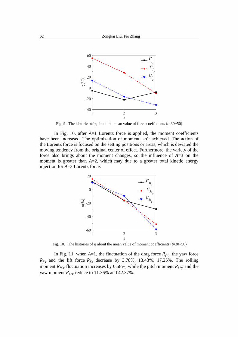
In Fig. 10, after A=1 Lorentz force is applied, the moment coefficients
have been increased. The optimization of moment isn’t achieved. The action of the Lorentz force is focused on the setting positions or areas, which is deviated the moving tendency from the original center of effect. Furthermore, the variety of the force also brings about the moment changes, so the influence of A=3 on the moment is greater than A=2, which may due to a greater total kinetic energy injection for A=3 Lorentz force.
Fig. 10. The histories of η about the mean value of moment coefficients (t=30~50)
In Fig. 11, when A=1, the fluctuation of the drag force 𝑅𝑅𝑓𝑓𝑀𝑀, the yaw force
𝑅𝑅𝑓𝑓𝑀𝑀 and the lift force 𝑅𝑅𝑓𝑓𝑀𝑀 decrease by 3.78%, 13.43%, 17.25%. The rolling moment 𝑅𝑅𝑀𝑀𝑀𝑀 fluctuation increases by 0.58%, while the pitch moment 𝑅𝑅𝑀𝑀𝑀𝑀 and the yaw moment 𝑅𝑅𝑀𝑀𝑀𝑀 reduce to 11.36% and 42.37%.
Research on the optimized control by local Lorentz force to adjust the submarine vibration in the seawater 63
After the application of the Lorentz force to the top surface of the sail A=2, the fluctuation of the drag force 𝑅𝑅𝑓𝑓𝑀𝑀, the yaw force 𝑅𝑅𝑓𝑓𝑀𝑀, and the lift force 𝑅𝑅𝑓𝑓𝑀𝑀 are severally reduced by about 99.94%, 99.75% and 94.63%, respectively. The fluctuation of the rolling moment 𝑅𝑅𝑀𝑀𝑀𝑀, the pitch moment 𝑅𝑅𝑀𝑀𝑀𝑀, the yaw moment 𝑅𝑅𝑀𝑀𝑀𝑀 have dropped by 94.54%, 98.90%, 99.86%, respectively. The force coefficients and the moment coefficients in three directions are all tend to stabilized after the Lorentz force is on.
In the context of the Lorentz force applied on the side surface of the elliptical cylinder A=3, as shown in Fig. 11, the fluctuation of the drag force 𝑅𝑅𝑓𝑓𝑀𝑀 the yaw force 𝑅𝑅𝑓𝑓𝑀𝑀 and the pitch force 𝑅𝑅𝑓𝑓𝑀𝑀 have dropped by 17.43%, 33.26%, 56.04%, respectively. The fluctuations of the rolling moment 𝑅𝑅𝑀𝑀𝑀𝑀 , the pitch moment 𝑅𝑅𝑀𝑀𝑀𝑀 and the yaw moment 𝑅𝑅𝑀𝑀𝑀𝑀 have reduced to 26.80%, 37.10% and 29.57%, as shown in Fig. 12.
For each control position, the fluctuation of the drag force can be smoothed in certain degrees, and the fluctuation of the drag force almost totally suppressed while the force is applied to the top surface of the sail A=2. A suitable application of Lorentz force may restrain the vortex generation and shedding. The deduction in coefficient of A=3 is larger than A=1. Consequently, the major induction factors for force instability mainly rely on the unsteady shedding of tip vortices.
Fig. 11. The histories of η about the fluctuation of the force coefficients
In Fig. 12, the most of moment fluctuations are reduced and the coefficient
𝜂𝜂 reduction reaches to the max value at A=2. Concerning on suppressing irregular vortices, reducing force and force fluctuation decrease, the optimization results of Lorentz force control can be arranged as follows, A=2 > A=3 > A=1.
The Lorentz force applied to the boundary layer is considered to have an effect on the vortex structure and the pressure distribution on submarine. In this paper, the major purpose of Lorentz force application is to reduce the drag force
64 Zongkai Liu, Fei Zhang
and suppress the forces’ vibration as well as the flow noise. For the case of A=1, the vortex structure generated by the flow around hemispherical fore-body is suppressed. However, the effect of Lorentz force on reducing drag, fluctuation decrease and noise reduction is not obvious. When A=2, the result is relatively ideal. The large scale tip vortices from the sail turn to be linear and the drag force coefficient and the moment coefficients featured as extremely tiny fluctuation. While A=3, the difference of the vorticity isosurfaces between the no control and Lorentz force control is not remarkable.
Fig. 12 . The histories of η about the fluctuation of the moment coefficients
4. Conclusions
In this paper, the finite volume method is used to analyze the evolution of the flow field around submarine and the force characteristics via the Lorentz force control, at Re=107 in a hypothetical sea environment. The results show that the vortices are appears a series of irregularly shed from the sail, and the fluctuations of force and moment may cause the instability of submarine during the straight course. Lorentz force on the local position of submarine surface has inhibitory the effect from vortices generation and shedding. The near-wall turbulent boundary layer can be eliminated. The distribution around the submarine of vortex is changed, and the drag force decreases. Meanwhile, the fluctuation can be suppressed. The sail of the submarine model is the main headstream products the greatest influence on the flow field around the submarine, and the streamwise Lorentz force control appears to have better effect on vortex elimination, drag reduction and noise reduction. And the Lorentz force applied on the top surface of the sail (A=2) could reach the best boundary layer adjustment effects rather than other cases.
Research on the optimized control by local Lorentz force to adjust the submarine vibration in the seawater 65
Acknowledgement
∗ Project supported by the National Natural Science Foundation of China (Grant No. 11702139), the Advanced Solid State Laser Technology Key Laboratory of the Ministry of Industry and Information Technology (Nanjing University of Science and Technology) (Grant No. 30918014115-009).
R E F E R E N C E S
[1]. N. Chase, P. M. Carrica. “Submarine propeller computations and application to self-propulsion of DARPA Suboff”, Ocean Engineering, vol. 60, 2013, pp. 68-80.
[2]. S. K. Shariati, S. H. Mousavizadegan. “The effect of appendages on the hydrodynamic characteristics of an underwater vehicle near the free surface”, Applied Ocean Research, vol. 67, 2017, pp. 31-43.
[3]. L. Chen, I. MacGillivray. Characteristics of sound radiation by turbulent flow over a hydrofoil and a bare-hull SUBOFF [C]//Acoustics 2011 Conference. 2011.
[4]. T. W. Berger, J. Kim, C. Lee, et al. “Turbulent boundary layer control utilizing the Lorentz force”, Physics of Fluids, vol. 12, no. 3, 2000, pp. 631-649.
[5]. H. Zhang, B. C. Fan, Z. H. Chen, et al. “Open-loop and optimal control of cylinder wake via electromagnetic fields”, Chinese Science Bulletin, vol. 53, no. 19, 2008, pp. 2946-2952.
[6]. Z. K. Liu, B. M. Zhou, H. X. Liu, et al. “Numerical investigation on feedback control of flow around an oscillating hydrofoil by Lorentz force”, Fluid Dynamics Research, vol. 45, no. 3, 2013, pp. 035502.
[7]. J. Ask, L. Davidson. “A numerical investigation of the flow past a generic side mirror and its impact on sound generation”, Journal of fluids Engineering, vol. 131, no. 6, 2009, pp. 061102.
[8]. Y. Huang, B. Zhou, Z. Tang, et al. “Transition scenario and transition control of the flow over a semi-infinite square leading-edge plate”, Physics of Fluids, vol. 29, no. 7, 2017, pp. 074105.
[9]. Z. K. Liu, Y. M. Bo, J. Wang and K. Cui. “Lorentz force filtering and fast steering mirror optical compensation in optical axis stability control for photoelectric mast”, Acta Physica Sinica, vol. 66, 2017.
[10]. H. Zhang, B. Fan, Z. Chen, et al. “Numerical study of the suppression mechanism of vortex-induced vibration by symmetric Lorentz forces”, Journal of Fluids and Structures, vol. 48, 2014, pp. 62-80.
[11]. H. Liu, B. Zhou, Z. Liu, et al. “Numerical simulation of flow around a body of revolution with an appendage controlled by electromagnetic force”, Proceedings of the Institution of Mechanical Engineers, Part G: Journal of Aerospace Engineering, vol. 227, no. 2, 2013, pp. 303-310.
[12]. T. Albrecht, J. Stiller, H. Metzkes, et al. “Electromagnetic flow control in poor conductors”, The European Physical Journal Special Topics, vol. 220, no. 1, 2013, pp. 275-285.
[13]. A. Altıntaş, L. Davidson. “Direct numerical simulation analysis of spanwise oscillating Lorentz force in turbulent channel flow at low Reynolds number”, Acta Mechanica, vol. 228, no. 4, 2017, pp. 1269-1286.
[15]. M. A. Olshanskii, Terekhov K M, Vassilevski Y V. An octree-based solver for the incompressible Navier–Stokes equations with enhanced stability and low dissipation”, Computers and Fluids, vol. 84, 2013, pp. 231-246.
[16]. S. Popinet. “Gerris: a tree-based adaptive solver for the incompressible Euler equations in complex geometries”, Journal of Computational Physics, vol. 190, no. 2, 2003, pp. 572-600.
[17]. S. Popinet, G. Rickard. “A tree-based solver for adaptive ocean modelling”, Ocean Modelling, vol. 16, no. 3-4, 2007, pp. 224-249.
[18]. G. Agbaglah, S. Delaux, Fuster D, et al. “Parallel simulation of multiphase flows using octree adaptivity and the volume-of-fluid method”, Comptes Rendus Mecanique, vol. 339, no. 2-3, 2011, pp. 194-207.
[19]. A. Fakhari, T. Lee. “Finite-difference lattice Boltzmann method with a block-structured adaptive-mesh-refinement technique”, Physical Review E, vol. 89, no. 3, 2014, pp. 033310.
[20]. Z. K. Liu, J. L. Lu, Y. M. BO, et al. “Investigation on the Perturbation Characteristics and Compound Axis Control for Submarine-borne Servo System”, Acta Armamentarii, vol. 40, no. 4, 2019, pp 837-847. (in Chinese)
[21]. J. Kim, D. Kim, H. Choi. “An immersed-boundary finite-volume method for simulations of flow in complex geometries”, Journal of computational physics, vol. 171, no. 1, 2001, pp. 132-150.
[22]. D. F. L. Labbé, P. A. Wilson. “A numerical investigation of the effects of the spanwise length on the 3-D wake of a circular cylinder”, Journal of Fluids and Structures, vol. 23, no. 8, 2007, pp. 1168-1188.
[23]. K. S. Breuer, J. Park, C. Henoch. “Actuation and control of a turbulent channel flow using Lorentz forces”, Physics of Fluids, vol. 16, no. 4, 2004, pp. 897-907.