Lee et al. EURASIP Journal on Wireless Communications and Networking 2012, 2012:219http://jis.eurasipjournals.com/content/2012/1/219
RESEARCH Open Access
Analysis of superframe adjustment and beacontransmission for IEEE 802.15.4 clustertree networksBih-Hwang Lee1*, Muhammad Udin Harun Al Rasyid1 and Huai-Kuei Wu2
Abstract
Wireless sensor networks based on the IEEE 802.15.4 standard are able to achieve low-power transmissions in thelow-rate and short-distance wireless personal area network (PAN). A cluster tree network consists of several clusters;each cluster has a coordinator, known as cluster coordinator, and several device nodes. In the cluster tree topologyof IEEE 802.15.4, a PAN coordinator periodically transmits beacon frames to its coordinator nodes as well as acoordinator node periodically transmit beacon frames to their device nodes. The main challenge in the cluster treenetwork is the collisions between beacons or even between beacon and data frames, which degrades the networkperformance. In order to decrease collisions, this article proposes the superframe adjustment and beacontransmission scheme (SABTS) by assigning the accurate values of beacon order and superframe order for the PANcoordinator, cluster coordinators, and device nodes, and deciding the precise time for the beacon transmission ofPAN and coordinator nodes. A Markov chain model for the cluster tree network is developed with taking intoaccount packet retransmission, acknowledgement, and defer transmission. Both analytical and simulation resultsshow that SABTS performs better than IEEE 802.15.4 standard in terms of the probability of successful transmission,network goodput, and energy consumption.
Keywords: Wireless sensor network, IEEE 802.15.4, Personal area network, Cluster tree topology, Markov chain
IntroductionWireless sensor networks based on the IEEE 802.15.4standard have been designed to specify the physical layer(PHY) and medium access control (MAC) sublayer forlow power consumption, short transmission range, andlow-rate wireless personal area network (LR-WPAN) [1].The IEEE 802.15.4 standard has three kinds of topology:star, peer-to-peer, and cluster tree topologies, which canoperate on beacon- and non-beacon-enabled modes.The beacon-enabled mode has the most unique featuresof IEEE 802.15.4, while the beacons are used tosynchronize the attached devices, to identify the per-sonal area network (PAN), and to describe the structureof the superframe.A cluster tree network consists of several clusters; each
cluster has a coordinator, known as cluster coordinator,
* Correspondence: [email protected] Taiwan University of Science and Technology, 43, Keelung Rd.,Section 4, Taipei 106, TaiwanFull list of author information is available at the end of the article
and several device nodes. A PAN coordinator serves asroot to form the first cluster and initiates the network.The PAN coordinator and coordinator nodes broadcastbeacon frames to their neighboring devices to completethe whole cluster networks. In a cluster tree topology,the PAN coordinator periodically transmits beaconframes to its coordinator nodes as well as the coordin-ator nodes periodically transmit beacon frames to theirdevice nodes. However, if the coordinator nodes sendbeacon frames at the same time, collisions will happenamong these beacon frames. Consequently, the childrennodes in the cluster cannot synchronize and communi-cate with their coordinators. The main challenge in thecluster tree network of IEEE 802.15.4 beacon-enabledmode is the collisions between beacons or even betweenbeacon and data frames, which degrades the networkperformance [2-4]. In other words, it is a crucial chal-lenge on the cluster scheduling and collision avoidance(CA) in a cluster tree network.
pen Access article distributed under the terms of the Creative Commonsg/licenses/by/2.0), which permits unrestricted use, distribution, and reproductionroperly cited.
Lee et al. EURASIP Journal on Wireless Communications and Networking 2012, 2012:219 Page 2 of 12http://jis.eurasipjournals.com/content/2012/1/219
To solve the aforementioned problem, a time divisionbeacon scheduling (TDBS) and superframe duration(SD) scheduling mechanisms are proposed [2]. The ideaof TDBS is to manage beacon frame transmission fromcoordinator nodes in a non-overlapping way while theidea of SD scheduling is to decide the duty cycle ofrouter nodes. A multi-dimensional scheduling (MDS) isproposed to avoid beacon collision in LR-WPAN, whichuses the clean channel searching scan to change the timeoffset to transmit a new beacon frame during the in-active period [3]. MDS can minimize the possibility ofbeacon collisions, but the power consumption of thePAN coordinator is more than that of IEEE 802.15.4standard due to the process of channel searching scanduring inactive period. Therefore, in order to improvethe network performance by decreasing beacon colli-sions as well as the collisions between beacon and datapackets, this article proposes the superframe adjustmentand beacon transmission scheme (SABTS) which isbased on the IEEE 802.15.4 slotted carrier sense multipleaccess with CA (CSMA/CA), to assign the accuratevalues of beacon order (BO) and superframe order (SO)for the PAN coordinator, cluster coordinators and devicenodes, and to decide the precise time for beacon trans-mission of PAN and coordinator nodes.A number of mathematical analysis models have been
proposed to analyze the performance of IEEE 802.15.4based on the Markov chain model without consideringpacket retransmissions [5-11]. Several modified Markovchain models including packet retransmissions havebeen investigated but not consider the defer transmis-sion [12-15], while the authors of [16-18] improve theMarkov chain models by considering the defer transmis-sion. An analytical model based on Markov chain formulti-hop cluster network has been studied without tak-ing into account the acknowledgement (ACK) to con-firm the successes of data packet transmission, the defertransmission, and packet retransmission [19]. Lastly, wepropose an analytical model based on Markov chain forSABTS cluster tree network with taking into accountpacket retransmission, ACK, and defer transmission bymodifying the Markov chain model from [17]. Themajor contribution of this article is to model the channel
0 1 2 3 4 5 6 7 8 9 10 11
GT
PAC
SD = aBaseSuperframeDuration * 2S
Active Period
BI = aBaseSuperframeDu
Beacon
Figure 1 An example of the superframe structure.
access for a cluster tree network to obtain networkgoodput and energy consumption based on the proposedMarkov chain.
Overview of IEEE 802.15.4In the beacon-enabled mode of IEEE 802.15.4, each nodeemploys two system parameters: BO and SO, which de-fine beacon interval (BI) and SD, respectively, i.e., BI =aBaseSuperframeDuration × 2BO and SD = aBaseSuper-frameDuration × 2SO, for 0 ≤ SO ≤ BO ≤ 14. aBaseSuper-frameDuration denotes the minimum number ofsymbols in an active period, which is fixed to 960 sym-bols. The active period of each superframe consists ofthree parts: beacon, contention access period (CAP) andcontention free period (CFP), while the active period isfurther equally divided into 16 time slots called aNum-SuperframeSlots. The length of one slot is equal toaBaseSlotDuration × 2SO symbols, where aBaseSlotDura-tion is the minimum number of symbols in a slot andequal to 60 symbols. Figure 1 shows an example of thesuperframe structure. In IEEE 802.15.4 standard, BO andSO shall be equal for all superframes on a PAN. Alldevices shall interact with the PAN only during the ac-tive portion of a superframe.In CAP, each node performs the CSMA/CA algorithm
before transmitting data frame or MAC commandframe. Each device maintains three parameters: thenumber of backoff (NB), contention window (CW), andbackoff exponent (BE). NB denotes the required NBwhile attempting to transmit data; CW denotes thenumber of backoff periods that need to be clear beforecommitting transmission; and BE denotes how manybackoff periods a device need to wait before trying to ac-cess the channel. The initial value of NB, CW, and BEare equal to 0, 2, and macMinBE, respectively, wheremacMinBE is equal to 3.In the located boundary of the next backoff period, a
device takes delay for random backoff between 0 and2BE – 1 unit backoff period (UBP), where UBP is equalto 20 symbols (or 80 bits). A device performs clear chan-nel assessment (CCA) to make sure whether the channelis idle or busy, when the number of random backoffperiods is decreased to 0. The value of CW will be
12 13 14 15
S GTS Inactive Period
PFC
O symbols
ration * 2BO symbols
Beacon
Figure 2 The flowchart of SABTS.
Lee et al. EURASIP Journal on Wireless Communications and Networking 2012, 2012:219 Page 3 of 12http://jis.eurasipjournals.com/content/2012/1/219
decreased by one if the channel is idle; and the secondCCA will be performed if the value of CW is not equalto 0. If the value of CW is equal to 0, it means that thechannel is idle after twice CCA; then a device is commit-ted the data transmission. However, if the CCA is busy,the value of CW will reset to 2; the value of NB isincreased by 1; and the value of BE is increased by 1 upto the maximum BE (macMaxBE), where the value mac-MaxBE is equal to 5. The device will repeatedly take ran-dom delay if the value of NB is less than the value ofmacMaxCSMABackoff, where the value of macMaxCS-MABackoff is equal to 4; and the transmission attemptis decided to be failure if the value of NB is greater thanthe value of macMaxCSMABackoff.
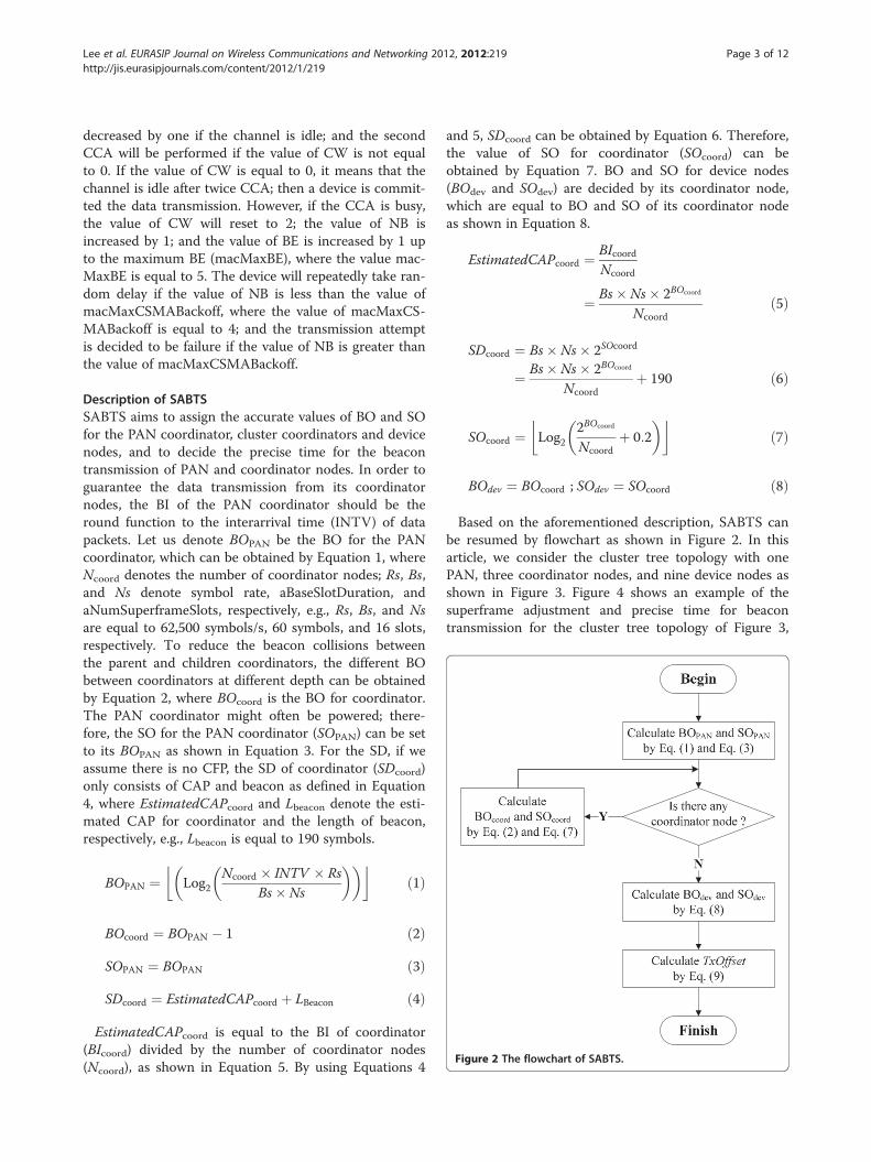
Description of SABTSSABTS aims to assign the accurate values of BO and SOfor the PAN coordinator, cluster coordinators and devicenodes, and to decide the precise time for the beacontransmission of PAN and coordinator nodes. In order toguarantee the data transmission from its coordinatornodes, the BI of the PAN coordinator should be theround function to the interarrival time (INTV) of datapackets. Let us denote BOPAN be the BO for the PANcoordinator, which can be obtained by Equation 1, whereNcoord denotes the number of coordinator nodes; Rs, Bs,and Ns denote symbol rate, aBaseSlotDuration, andaNumSuperframeSlots, respectively, e.g., Rs, Bs, and Nsare equal to 62,500 symbols/s, 60 symbols, and 16 slots,respectively. To reduce the beacon collisions betweenthe parent and children coordinators, the different BObetween coordinators at different depth can be obtainedby Equation 2, where BOcoord is the BO for coordinator.The PAN coordinator might often be powered; there-fore, the SO for the PAN coordinator (SOPAN) can be setto its BOPAN as shown in Equation 3. For the SD, if weassume there is no CFP, the SD of coordinator (SDcoord)only consists of CAP and beacon as defined in Equation4, where EstimatedCAPcoord and Lbeacon denote the esti-mated CAP for coordinator and the length of beacon,respectively, e.g., Lbeacon is equal to 190 symbols.
BOPAN ¼ Log2Ncoord � INTV � Rs
Bs� Ns
� �� �� �ð1Þ
BOcoord ¼ BOPAN � 1 ð2Þ
SOPAN ¼ BOPAN ð3Þ
SDcoord ¼ EstimatedCAPcoord þ LBeacon ð4Þ
EstimatedCAPcoord is equal to the BI of coordinator(BIcoord) divided by the number of coordinator nodes(Ncoord), as shown in Equation 5. By using Equations 4
and 5, SDcoord can be obtained by Equation 6. Therefore,the value of SO for coordinator (SOcoord) can beobtained by Equation 7. BO and SO for device nodes(BOdev and SOdev) are decided by its coordinator node,which are equal to BO and SO of its coordinator nodeas shown in Equation 8.
EstimatedCAPcoord ¼ BIcoordNcoord
¼ Bs� Ns� 2BOcoord
Ncoordð5Þ
SDcoord ¼ Bs� Ns� 2SOcoord
¼ Bs� Ns� 2BOcoord
Ncoordþ 190 ð6Þ
SOcoord ¼ Log22BOcoord
Ncoordþ 0:2
� �� �ð7Þ
BOdev ¼ BOcoord ; SOdev ¼ SOcoord ð8Þ
Based on the aforementioned description, SABTS canbe resumed by flowchart as shown in Figure 2. In thisarticle, we consider the cluster tree topology with onePAN, three coordinator nodes, and nine device nodes asshown in Figure 3. Figure 4 shows an example of thesuperframe adjustment and precise time for beacontransmission for the cluster tree topology of Figure 3,
Dev2Dev3Dev1
Dev4
Dev5
Dev6Dev7
Dev8
Dev9 Dev4
Dev5
Dev6
Coord2Coord2Coord3
Coord1
PAN
Figure 3 The selected cluster tree topology.
Lee et al. EURASIP Journal on Wireless Communications and Networking 2012, 2012:219 Page 4 of 12http://jis.eurasipjournals.com/content/2012/1/219
while INTV of each device node is equal to 0.1. Asshown in Figure 4, we get the different starting time ofbeacon transmission among coordinator nodes to avoidbeacon collisions. Furthermore, the coordinator nodesand device nodes can save energy consumption duringinactive periods. By using SABTS, we get the values ofBO and SO for PAN to be equal to 4; the value of BOfor each coordinator node and device node is equal to 3;and the value of SO for each coordinator node and de-vice node is equal to 1.
Figure 4 An example of SABTS for three coordinator nodes.
In order to reduce the collisions of the beacon trans-missions among coordinator nodes, SABTS adjusts thebeacon starting times of PAN and coordinator nodes.Let us denote TxOffsetPAN and TxOffseti to be the beaconstarting times of PAN and the ith coordinator node, re-spectively. TxOffsetPAN starts at the beginning of super-frame, then TxOffseti is adjusted by Equation 9, whereSDcoordi−1 denotes the SD of the (i – 1)th coordinatornode.
TxOffseti ¼TxOffsetPAN þ LBeacon
Rs; i ¼ 1
TxOffseti�1 þ LBeaconRs
þ SDcoordi�1 ;
2≤i≤Ncoord
8>>><>>>:
ð9Þ
Analysis of SABTSIn this section, the Markov chain model for SABTS inthe case of the acknowledged uplink data transmission isanalyzed to obtain the stationary probabilities, whosestate transition diagram is shown as Figure 5. Let bi,j,k bethe stationary probability at the stochastic state (s(t) = i,c(t) = j, and r(t) = k), where s(t), c(t), and r(t) representbackoff stage, backoff counter, and number of retrans-missions, respectively, shown as Equation 10, where bi,-1,k,bi,-2,k, and bi,-3,k are the stationary probabilities for thefirst CCA1, the second CCA2, and packet transmission,respectively, at the ith backoff stage and the kth re-transmission. Let bSi,k and bCi,k be the stationary prob-abilities of the successful transmission and collision atthe states of Si,k and Ci,k shown as Equations (11) and(12), respectively, where m and R are the maximum NB
Figure 5 The Markov chain model for CSMA/CA.
Lee et al. EURASIP Journal on Wireless Communications and Networking 2012, 2012:219 Page 5 of 12http://jis.eurasipjournals.com/content/2012/1/219
stage and retransmissions, i.e., they are equal to 4 and 3,respectively.
ð12ÞThe parameters used in the Markov chain model are
explained as follows. An IDLE state means that a devicenode has no packet to transmit. Let wi = 2BEi be thebackoff window at the ith backoff stage of a device,where BEi = 3, 4, 5, 5, and 5 for 0 ≤ i ≤m. Let us denoteq to be the probability that packet arrives during theactive period, which can be obtained by Equation 13,where Ldata, Rb, and SDT are packet length (in bits), datarate (i.e., 250 kbps), and the SD time (in seconds),
respectively; where SDT is equals to SDRs , and
1INTV is the
number of packets in SDT.
q ¼ LdataINTV � Rb � SDT
ð13Þ
The MAC sublayer should transmit packet if theremaining CSMA/CA steps, i.e., two CCA analyses,frame transmission, and any ACK, can be completed be-fore the end of CAP. Conversely, if the current CAP hasnot enough slots to transmit data packets, it shoulddefer transmission until the beginning of the CAP in thenext superframe. Let us denote d to be the probability ofdefer transmission, which can be obtained by Equation14, where Ttxcca, Ttx, Tack, and Ttxack are the CCA trans-mission time, packet transmission time, time to wait forACK, and time to transmit ACK from receiver to trans-mitter node, respectively.
d ¼ 2Ttxcca þ Ttx þ Tack þ Ttxack
SDTð14Þ
Let α and β be the probabilities that CCA1 and CCA2
are busy, respectively. CCA1 busy means that the tagged
Lee et al. EURASIP Journal on Wireless Communications and Networking 2012, 2012:219 Page 6 of 12http://jis.eurasipjournals.com/content/2012/1/219
node at one of the CCA1 states while at least one of theother nodes at packet transmission state, while CCA2
busy means that the tagged node at one of the CCA2
states while at least one of the other nodes at packettransmission state. Let us denote Pcoll to be the probabil-ity of the collision of packet transmission, i.e., the taggednode at packet transmission state while at least one ofother nodes in the packet transmission state at the sametime. Let us also denote Pfail1 and Pfail2 to be the prob-abilities of fail transmission due to the maximum num-ber of retransmissions after collisions and due to nochannel to use after reaching the maximum backoffstage at the maximum retransmission stage, respectively.To analyze the Markov chain model, several state tran-
sition probabilities are evaluated as shown from Equa-tions 15 to 23. Equation 15 states the probability thatthe backoff counter is decreased after each slot. Equation16 gives the probability of finding busy channel either inCCA1 and CCA2. Equation 17 states the probability ofpicking a backoff state in the next retransmission stageafter the collision of packet transmission when havingenough time to send packet in the remaining activeperiod and channel idle in both CCA1 and CCA2. Equa-tion 18 states the probability of entering the IDLE stateafter the collision of packet transmission while reach themaximum retransmission stage after finding theremaining active period to be enough to send packetand channel idle in both CCA1 and CCA2. Equation 19gives probability that the remaining CAP is not enoughto send packet and need to defer and pick backoff statein the next superframe. Equation 20 states the probabil-ity of successful packet transmission and picking newrandom backoff at the first backoff stage. Equation 21states the probability of entering the IDLE state if thenode has no data packet to transmit after successfulpacket transmission. Equation 22 states the probabilityof entering the IDLE state due to channel access failure.Equation 23 states the probability of going to the firstbackoff stage from the IDLE state if the node has datapacket to transmit.
Pði; j; kji; jþ 1; kÞ ¼ 1; for i∈ð0; mÞ; j∈ð0; wi � 2Þ;k∈ð0; RÞ ð15Þ
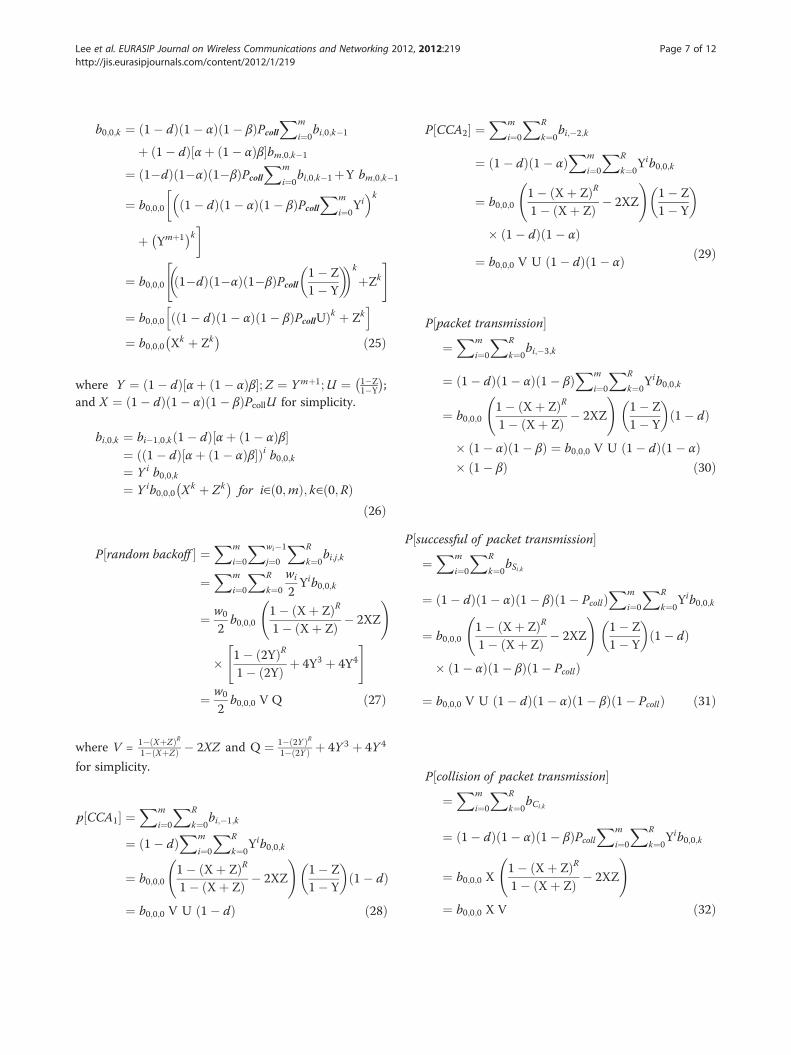
By using Equation 16, the stationary probability bi,j,kcan be obtained by Equation 24. From Equation 17, b0,0,kcan be obtained by Equation 25, where Y and X are theprobabilities of entering the next backoff stage and thecollision of packet transmission in a certain backoffstage, respectively. Similarly, bi,0,k can be obtained byEquation 26. Finally, the steady-state probabilities to per-form random backoff, CCA1, CCA2, packet transmission,successful of packet transmission, collision of packettransmission, and idle can be obtained from Equations27 to 33, respectively. Since the sum of probabilities inthe Markov chain must be equal to one, we have Equa-tion 34. By using Equations 27 to 34, we can get thevalue of b0,0,0 easily by using excel spreadsheet.
bi;j;k ¼ wi � jwi
bi�1;0;kð1� dÞ½αþ ð1� αÞβ�
¼ wi � jwi
bi;0;k ð24Þ
1
Lee et al. EURASIP Journal on Wireless Communications and Networking 2012, 2012:219 Page 7 of 12http://jis.eurasipjournals.com/content/2012/1/219
b0;0;k ¼ ð1� dÞð1� αÞð1� βÞPcoll
Xm
i¼0bi;0;k�1
þ ð1� dÞ½αþ ð1� αÞβ�bm;0;k�1
¼ ð1�dÞð1�αÞð1�βÞPcollXm
i¼0bi;0;k�1þY bm;0;k�
¼ b0;0;0 ð1� dÞð1� αÞð1� βÞPcollXm
i¼0Yi
� k
þ Ymþ1� �k
¼ b0;0;0 ð1�dÞð1�αÞð1�βÞPcoll1� Z1� Y
� �� �k
þZk
" #
¼ b0;0;0 ð1� dÞð1� αÞð1� βÞPcollUð Þk þ Zkh i
¼ b0;0;0 Xk þ Zk� � ð25Þ
where Y ¼ ð1� dÞ½αþ ð1� αÞβ�;Z ¼ Ymþ1;U ¼ 1�Z1�Y
� �;
and X ¼ ð1� dÞð1� αÞð1� βÞPcollU for simplicity.
bi;0;k ¼ bi�1;0;kð1� dÞ½αþ ð1� αÞβ�¼ ð1� dÞ½αþ ð1� αÞβ�ð Þi b0;0;k¼ Y i b0;0;k¼ Y ib0;0;0 Xk þ Zk
� �for i∈ð0;mÞ; k∈ð0;RÞ
ð26Þ
P random backoff½ � ¼Xm
i¼0
Xwi�1
j¼0
XR
k¼0bi;j;k
¼Xm
i¼0
XR
k¼0
wi
2Yib0;0;k
¼ w0
2b0;0;0
1� ðXþ ZÞR1� ðXþ ZÞ � 2XZ
!
� 1� ð2YÞR1� ð2YÞ þ 4Y3 þ 4Y4
" #
¼ w0
2b0;0;0 V Q ð27Þ
where V = 1�ðXþZÞR1�ðXþZÞ � 2XZ and Q ¼ 1�ð2Y ÞR
1�ð2Y Þ þ 4Y 3 þ 4Y 4
for simplicity.
p½CCA1� ¼Xm
i¼0
XR
k¼0bi;�1;k
¼ ð1� dÞXm
i¼0
XR
k¼0Yib0;0;k
¼ b0;0;01� ðXþ ZÞR1� ðXþ ZÞ � 2XZ
!1� Z1� Y
� �ð1� dÞ
¼ b0;0;0 V U ð1� dÞ ð28Þ
P CCA2½ � ¼Xm
i¼0
XR
k¼0bi;�2;k
¼ ð1� dÞð1� αÞXm
i¼0
XR
k¼0Yib0;0;k
¼ b0;0;01� ðXþ ZÞR1� ðXþ ZÞ � 2XZ
!1� Z1� Y
� �
� ð1� dÞð1� αÞ¼ b0;0;0 V U ð1� dÞð1� αÞ ð29Þ
P packet transmission½ �¼Xm
i¼0
XR
k¼0bi;�3;k
¼ ð1� dÞð1� αÞð1� βÞXm
i¼0
XR
k¼0Yib0;0;k
¼ b0;0;01� ðXþ ZÞR1� ðXþ ZÞ � 2XZ
!1� Z1� Y
� �ð1� dÞ
� ð1� αÞð1� βÞ ¼ b0;0;0 V U ð1� dÞð1� αÞ� ð1� βÞ ð30Þ
P successful of packet transmission½ �¼Xm
i¼0
XR
k¼0bSi;k
¼ ð1� dÞð1� αÞð1� βÞð1� PcollÞXm
i¼0
XR
k¼0Yib0;0;k
¼ b0;0;01� ðXþ ZÞR1� ðXþ ZÞ � 2XZ
!1� Z1� Y
� �ð1� dÞ
� ð1� αÞð1� βÞð1� PcollÞ
¼ b0;0;0 V U ð1� dÞð1� αÞð1� βÞð1� PcollÞ ð31Þ
P collision of packet transmission½ �¼Xm
i¼0
XR
k¼0bCi;k
¼ ð1� dÞð1� αÞð1� βÞPcollXm
i¼0
XR
k¼0Yib0;0;k
¼ b0;0;0 X1� ðXþ ZÞR1� ðXþ ZÞ � 2XZ
!
¼ b0;0;0 X V ð32Þ
Lee et al. EURASIP Journal on Wireless Communications and Networking 2012, 2012:219 Page 8 of 12http://jis.eurasipjournals.com/content/2012/1/219
P IDLE½ � ¼ ð1� qÞXm
i¼0
XR
k¼0bSi;k þ ð1� qÞ
Xm
i¼0bCi;R þ ð1� qÞd
Xm
i¼0bi;0;0 þ ð1� qÞY bm;0;R þ ð1� qÞP½IDLE�
¼ ð1� qÞq
Xm
i¼0
XR
k¼0bSi;k þ
Xm
i¼0bCi;R þ d
Xm
i¼0bi;0;0 þ Y bm;0;R
h i
¼ ð1� qÞq
b0;0;0
1� ðXþ ZÞR1� ðXþ ZÞ � 2XZ
!1� Z1� Y
� �ð1� dÞð1� αÞð1� βÞð1� PcollÞ
þðX2 þ Z2ÞXþ d1� Z1� Y
� �þ ZðX2 þ Z2Þ
26664
37775
¼ ð1� qÞq
b0;0;0 V Uð1� dÞð1� αÞð1� βÞð1� PcollÞ þ ðX2 þ Z2ÞðX þ ZÞ þ d U� �
ð33ÞXm
i¼0
Xwi�1
j¼0
XR
k¼0bi;j;k þ
Xm
i¼0
XR
k¼0bi;�1;k þ
Xm
i¼0
XR
k¼0bi;�2;k þ
Xm
i¼0
XR
k¼0bi;�3;k þ
Xm
i¼0
XR
k¼0bSi;k
þXm
i¼0
XR
k¼0bCi;k þ P½IDLE� ¼ 1 ð34Þ
Let ϕ1 and ϕ2 be the conditional probabilities that a tagged node will be at one of the CCA1 states after backoffand at one of the CCA2 states after sensing channel idle in the CCA1, which can be obtained by Equations 35 and36, respectively. Let us denote τ to be the probability that a tagged node can transmit a packet, i.e., the tagged nodeis in one of the CCA1 states and senses the CCA2 is idle, while the other nodes do not in the CCA1 state, which canbe expressed by Equation 37, where Nch is the number of children nodes of certain coordinator nodes. Therefore, theprevious mentioned probabilities of α, β, Pcoll, Pfail1, and Pfail2 can be expressed by Equations 38 to 42, respectively.
ϕ1 ¼Xm
i¼0
XR
k¼0bi;�1;kXm
i¼0
XR
k¼0bi;�1;k þ
Xm
i¼0
Xwi�1
j¼0
XR
k¼0bi;j;k
¼
1� ðX þ ZÞRþ1
1� ðX þ ZÞ � 2XZ
!1� Z1� Y
� �ð1� dÞ
1� ðX þ ZÞRþ1
1� ðX þ ZÞ � 2XZ
!1� Z1� Y
� �ð1� dÞ þ w0
21� ð2Y ÞRþ1
1� ð2Y Þ þ 4Y 3 þ 4Y 4
!" #
¼ V 0Uð1� dÞV 0 Uð1� dÞ þ w0
2Q0
h ið35Þ
where V 0 ¼ 1�ðXþZÞRþ1
1�ðXþZÞ � 2XZ and Q0 ¼ 1�ð2Y ÞRþ1
1�ð2Y Þ þ 4Y 3 þ 4Y 4 for simplicity.
ϕ2 ¼Xm
i¼0
XR
k¼0bi;�2;kXm
i¼0
XR
k¼0bi;�1;k þ
Xm
i¼0
XR
k¼0bi;�2;k þ
Xm
i¼0
Xwi�1
j¼0
XR
k¼0bi;j;k
¼
1� ðX þ ZÞRþ1
1� ðX þ ZÞ � 2XZ
!1� Z1� Y
� �ð1� dÞð1� αÞ
1� ðX þ ZÞRþ1
1� ðX þ ZÞ � 2XZ
!1� Z1� Y
� �ð1� dÞð2� αÞ þ w0
21� ð2Y ÞRþ1
1� ð2Y Þ þ 4Y 3 þ 4Y 4
! !" #
¼ V 0Uð1� dÞð1� αÞV 0 Uð1� dÞð2� αÞ þ w0
2Q0
h ið36Þ
Lee et al. EURASIP Journal on Wireless Communications and Networking 2012, 2012:219 Page 9 of 12http://jis.eurasipjournals.com/content/2012/1/219
Let us denote Pdr to be the probability of a packetbeing dropped due to collision retransmission, whichcan be expressed by Equation 43. Because the probabilityof collision increases as the value of INTV decreases, wedefine PINTV be the fraction time of the total number ofdata packets and ACK packets to the CAP time of thesuperframe as expressed by Equation 44, where inter-frame space (IFS) is the minimum period between twosuccessive frames transmitted from device [1]. Let us de-note Pdropcoord and Psuccoord to be the probabilities ofpacket dropped and successful transmission from devicenode to its coordinator, respectively, which can beobtained by Equations 45 and 46. Similarly, let us denotePdropPAN and PsucPAN be the probabilities of packetdropped and successful transmission from coordinatornode to the PAN coordinator, respectively, which can beobtained by Equations 47 and 48.
Pdr ¼XR
k¼1ðPcollÞk ð43Þ
PINTV ¼ Ldata þ IFS þ ACKINTV � SDT
� �Nch�1
ð44Þ
Pdropcoord ¼ Pfail1 þ Pfail2 þ Pdr ; if PINTV < 11; if PINTV ¼ 1
�ð45Þ
Psuccoord ¼ 1� Pdropcoord ð46Þ
PdropPAN ¼ ðPdropcoordÞ2 ð47Þ
PsucPAN ¼ ð1� PdropcoordÞð1� PdropPANÞ ð48Þ
Based on the aforementioned analyses, the number ofsuccessful packets received by PAN (NrecvPAN) and thenetwork goodput (G), can be expressed by Equations 49and 50, respectively, where Ndev, Nbeacon, and Tsim arethe number of device nodes in network, the number ofobserved BIs of PAN, and the observed simulation time(in seconds), respectively.
NrecvPAN ¼ Ndev PsucPAN Tsim
INTVð49Þ
G ¼ NrecvPAN LdataNbeacon BIPAN
ð50Þ
Basically, the total energy consumption of a clustertree network consists of the energy consumptions by de-vice nodes, coordinator node, and the PAN coordinator,denoted by Edev, Ecoord, and EPAN, respectively. Let us de-note PWidle, PWsleep, PWtx, and PWrx to be the powerconsumptions for idle, sleeping, transmitting a packet,and receiving a packet, respectively. Let us also denoteLcca, Lbeacon, and Lack to be the lengths of CCA, beacon,and ACK transmissions, respectively. Moreover, let usdenote DCdev, DCcoord, and DCPAN to be the duty cyclesof device nodes, coordinator nodes, and the PAN coord-inator, respectively.The energy consumptions of a cluster tree network are
analyzed as follows. The energy consumption of devicenodes consist of seven parts as shown in Equation 51,i.e., the seven parts of energy consumptions are in orderfor backoff, CCA transmission, data packet transmission,idle, receiving beacon from its coordinator, receivingACK, and sleeping, respectively, where dnode is the dis-tance between device nodes (or coordinator nodes) andits coordinators (or the PAN coordinator). Similarly, theenergy consumption of coordinator nodes can beobtained by Equation 52, which consists of 10 parts asin order for backoff, receiving data packet transmissionfrom its children node, transmitting ACK to its childrennodes, transmitting CCA, transmitting data packet, re-ceiving ACK from its coordinator (i.e., PAN coordin-ator), idle, transmitting beacon, receiving beacon, andsleeping, respectively. The energy consumption of thePAN coordinator can be obtained by Equation 53, whichconsists of five parts as in order for idle, transmittingbeacon, receiving data packet, transmitting ACK, andsleeping. Finally, the total energy consumption of a clus-ter tree network, Etotal, can be obtained by Equation 54.
Lee et al. EURASIP Journal on Wireless Communications and Networking 2012, 2012:219 Page 10 of 12http://jis.eurasipjournals.com/content/2012/1/219
Edev ¼ Ndev Tsim
PWidleSDdev
BIPAN
Xm
i¼0
Xwi�1
j¼0
XR
k¼0bi;j;k
� �þ 2 PWtx
INTVLccaRb
dnodeXm
i¼0
XR
k¼0ðbi;�1;k þ bi;�2;kÞ
� �
þ PWtx
INTVLdataRb
Psuccoord dnode
� �þ PWidle P½IDLE� SDdev
BIPAN
� �
þ PWrx
Rb
LbeaconBIcoord
þ PWrx
INTVLackRb
Psuccoord
� �þ PWsleepð1� DCdevÞ BIdev
BIPAN
� �
26666664
37777775
ð51Þ
Ecoord ¼ Ncoord Tsim
Nch PWidleSDcoord
BIPAN
Xm
i¼0
Xwi�1
j¼0
XR
k¼0bi;j;k
� �þ Nch Psuccoord
PWrx
INTVLdataRb
� �
þ Nch dnode PsuccoordPWtx
INTVLackRb
� �
þ 2 PWtx
INTVLccaRb
Psuccoord dnodeXm
i¼0
XR
k¼0bi;�1;k þ bi;�2;k� �� �
þ PWtx
INTVLdataRb
Psuccoord PsucPAN dnode
� �þ PWrx
INTVLackRb
PsucPAN
� �
þ PWidle P½IDLE� SDcoord
BIPAN
� �þ PWtx
LbeaconRb
dnodeBIcoord
� �
þ PWrx
Rb
LbeaconBIPAN
� �þ PWsleepð1� DCcoordÞBIcoordBIPAN
� �
266666666666666666664
377777777777777777775
ð52Þ
EPAN ¼ Tsim
PWidle P½IDLE� SDPAN
BIPAN
� �þ PWtx
LbeaconRb
dnodeBIPAN
� �
þ PWrx
INTVLdataRb
PsucPAN Ndev
� �þ PWtx
INTVLackRb
PsucPAN dnode Ndev
� �þPWsleepð1� DCPANÞ
266664
377775 ð53Þ
Etotal ¼ Edev þ Ecoord þ EPAN ð54Þ
Simulation and analysis resultsIn this section, simulation experiments are performed byusing the extended network simulator NS-2 to validatethe analysis and performance evaluation. We consider acluster topology with 1 PAN coordinator, 3 coordinatornodes, and 9 device nodes as shown in Figure 3, wherethe distance between nodes (dnode) is equal to 10 m. Thepacket arrival rate follows the Poisson distribution withthe INTV of data packets from 0.1 to 1, where packetshave the same length of 560 bits. To simulate the per-formance of power consumption, we consider the radioparameters of Chipcon’s CC2420 2.4 GHz for the IEEE802.15.4 RF transceiver [20], where the transmittingpower PWtx, the receiving power PWrx, the idle powerPWidle, and the sleeping power per time unit PWsleep are31.32 mW, 35.28 mW, 712 μW, and 144 nW, respect-ively [16]. The BO and SO settings follow the proposedSABTS algorithm, but they are fixed for IEEE 802.15.4standard, i.e., BO = SO = 6. Table 1 summarizes thesimulation parameters. We compute the probabilities ofcollision of packet transmission and entering the nextbackoff stage in a certain backoff stage. We also
compare the analytical (ana) and simulation (sim) resultsbetween the proposed algorithm (SABTS) and IEEE802.15.4 standard (Std) for network goodput, total net-work energy consumption, and the probability of suc-cessful packet transmission arriving at PAN.Figure 6 shows the probabilities of collision of packet
transmission and entering the next backoff stage in acertain backoff stage, denoted as X and Y, respectively,against the INTV of data packets by analytical model.The probabilities of X and Y of SABTS are lesser thanthose of IEEE 802.15.4 standard. Normally, the lesserprobabilities of X and Y, the higher probability of suc-cessful packet transmission, which implies the lesser en-ergy consumption needed for packet transmission, i.e.,SABTS should have higher network goodput and lesserenergy consumption than those of IEEE 802.15.4standard.Figure 7 shows the probability of successful transmis-
sion arrives at the PAN coordinator (PsucPAN) against theINTV of data packets by analytical and simulation.SABTS obtains higher probability of successful transmis-sion arriving at the PAN coordinator than that of IEEE
Table 1 The simulation parameters
Parameter Value
Channel bandwidth 250 kbps
Packet length (Ldata) 560 bits
UBP 80 bits
MAC header 2 UBP
ACK length (LACK) 88 bits
dnode 10 m
PWtx 31.32 mW
PWrx 35.28 mW
PWidle 712 μW
PWsleep 144 nW
BO = SO (Std.) 6Figure 7 The probability of successful transmission against theINTV of data packets.
Lee et al. EURASIP Journal on Wireless Communications and Networking 2012, 2012:219 Page 11 of 12http://jis.eurasipjournals.com/content/2012/1/219
802.15.4 standard because the length of active periodand the beacon transmission time are managed appro-priately. The probability of successful transmission ofIEEE 802.15.4 standard decreases more as traffic loadincreases because the heavy collision occurs either be-tween beacons or between beacon and data frame.Figure 8 shows the network goodput against the INTV
of data packets. The network goodput obtained by simu-lation is very close to that obtained by analysis model. Itis obvious the network goodput of SABTS is higher thanthat of IEEE 802.15.4 standard especially when the trafficload increases. The probability of collisions of transmit-ting beacons and data packets can be decreased, becausethe beacon transmission time and active period lengthare accurately managed by SABTS. In the light trafficload (i.e., INTV is equal to 1 and 0.9), the network good-put of SABTS is almost same as those of IEEE 802.15.4standard; however, SABTS outperforms IEEE 802.15.4standard as the traffic load increases.Figure 9 shows the network energy consumption
against the INTV of data packets. SABTS consumeslesser network energy than that of IEEE 802.15.4
Figure 6 Probabilities of collision, X, and entering next backoff,Y, against the INTV of data packets.
standard. The energy consumption is obtained by sum-ming the energy consumptions of the PAN coordinator,coordinator nodes, and children device nodes. BySABTS, the coordinator nodes and device nodes cansave energy consumption during the inactive period asshown in Figure 4. Moreover, SABTS gains the greaterprobability of successful transmission than that of IEEE802.15.4 standard especially in heavy traffic load, whichmeans that SABTS minimizes the energy consumptionwhen retransmitting data packets.
ConclusionsIn this article, SABTS has been proposed to adjust twosystem parameters of superframe (i.e., BO and SO) andset the precise time for beacon transmission to achievelow energy consumption and to alleviate the collision ofbeacon and data packet transmissions. This article pre-sented a comprehensive Markov chain analysis of IEEE802.15.4, specifically for cluster tree network, to predictthe network goodput as well as the network energy
Figure 8 The network goodput against the INTV of datapackets.
Figure 9 The network goodput against the INTV of datapackets.
Lee et al. EURASIP Journal on Wireless Communications and Networking 2012, 2012:219 Page 12 of 12http://jis.eurasipjournals.com/content/2012/1/219
consumption. The validity of the analytical model isshown by closely matching its predictions to the simula-tion results. The results obtained by analytical modeland simulation experiments show that SABTS performsbetter than IEEE 802.15.4 standard especially in the net-work goodput and the network energy consumption.However, this article pays much attention to the slottedCSMA/CA channel access mechanism within the CAPof a superframe, but for certain applications with low la-tency or specific bandwidth requirements it needs dedi-cated guaranteed time slots (GTS) channel to transmitits data packets without contention. For further research,the SABTS algorithm will be expected to consider GTSwithin the CFP of a superframe to improve the networkperformance.
AbbreviationsACK: Acknowledgement; BE: Backoff exponent; BI: Beacon interval;BO: Beacon order; CAP: Contention access period; CCA: Clear channelassessment; CFP: Contention free period; CSMA/CA: Carrier sense multipleaccess with collision avoidance; CW: Contention window; IFS: Interframespace; INTV: Interarrival time of data packets; LR-WPAN: Low-rate wirelesspersonal area network; MAC: Medium access control sublayer; NB: Number ofbackoffs; PAN: Personal area network; SD: Superframe duration (in symbols);SDT: Superframe duration time (in seconds); SO: Superframe order; UBP: Unitbackoff period (80 bits).
Competing interestsThe authors declare that they have no competing interests.
AcknowledgmentsThis study was supported in part by the National Science Council (NSC) ofTaiwan under Grant No. NSC 96-2221-E-011-055.
Author details1National Taiwan University of Science and Technology, 43, Keelung Rd.,Section 4, Taipei 106, Taiwan. 2Ling Tung University, 1, Ling Tung Rd.,Taichung 408, Taiwan.
Received: 24 March 2012 Accepted: 4 June 2012Published: 17 July 2012
References1. IEEE 802.15.4, Part 15.4, Wireless Medium Access Control (MAC) and Physical
Layer (PHY) Specifications for Low-Rate Wireless Personal Area Networks(WPANs) (IEEE standard for information technology, 2006)
2. A Koubaa, A Cunha, M Alves, E Tovar, TDBS: a time division beaconscheduling mechanism for ZigBee cluster-tree wireless sensor networks.Real-Time Syst. J. 40(3), 321–354 (2008)
3. J-W Kim, J Kim, D-S Eom, Multi-dimensional channel management schemeto avoid beacon collision in LR-WPAN. IEEE Trans. Consum. Electron. 54(2),396–404 (2008)
4. J Lu, A Van Den Bossche, E Campo, A new beacon scheduling mechanismfor mesh wireless personal area networks based on IEEE 802.15.4, in IEEE16th Conference on Emerging Technologies & Factory Automation (ETFA),(Toulouse, France, 2011), pp. 1–4
5. TR Park, TH Kim, JY Choi, S Choi, WH Kwon, Throughput and energyconsumption analysis of IEEE 802.15.4 slotted CSMA/CA. IEEE. Electron. Lett.41(18), 1017–1019 (2005)
6. T-J Lee, HR Lee, MY Chung, MAC throughput limit analysis of slotted CSMA/CA in IEEE 802.15.4 WPAN. IEEE Commun. Lett. 10(7), 561–563 (2006)
7. S Pollin, M Ergen, S Ergen, B Bougard, L Der Perre, I Moerman, A Bahai,P Varaiya, F Catthoor, Performance analysis of slotted carrier sense IEEE802.15.4 medium access layer. IEEE Trans. Wirel. Commun. 7(9), 3359–3371(2008)
8. Y Zhang, F Shu, Packet size optimization for goodput and energy efficiencyenhancement in slotted IEEE 802.15.4 networks, in IEEE WirelessCommunications and Networking Conference, (Budapest, Hungary, 2009),pp. 1–6
9. J He, Z Tang, H-H Chen, Q Zhang, An accurate and scalable analyticalmodel for IEEE 802.15.4 slotted CSMA/CA networks. IEEE Trans. Wirel.Commun. 8(1), 440–448 (2009)
10. Z Xiao, C He, L Jiang, An analytical model for IEEE 802.15.4 with sleep modebased on time-varying queue, in IEEE International Conference onCommunications (ICC), (Kyoto, Japan, 2011)
11. C Buratti, Performance analysis of IEEE 802.15.4 beacon-enabled mode. IEEETrans. Veh. Technol. 59, 2031–2045 (2010)
12. Z Tao, S Panwar, D Gu, J Zhang, Performance analysis and a proposedimprovement for the IEEE 802.15.4 contention access period, vol. 4, in IEEEWireless Communications and Networking Conference, (Las Vegas, USA, 2006),pp. 1811–1818
13. P Park, P Di Marco, P Soldati, C Fischione, KH Johansson, A generalizedMarkov chain model for effective analysis of slotted IEEE 802.15.4, in IEEE 6thInternational Conference on Mobile Adhoc and Sensor Systems, (Macau, China,2009), pp. 130–139
14. Y-K Huang, A-C Pang, H-N Hung, A comprehensive analysis of low-poweroperation for beacon-enabled IEEE 802.15.4 wireless networks. IEEE Trans.Wirel. Commun. 8(11), 5601–5611 (2009)
15. M Khanafer, M Guennoun, HT Mouftah, Adaptive sleeping periods in IEEE802.15.4 for efficient energy savings: markov-based theoretical analysis, inIEEE International Conference on Communications (ICC), (Kyoto, Japan, 2011)
16. B Gao, C He, L Jiang, Modeling and analysis of IEEE 802.15.4 CSMA/CA withsleep mode enabled, in International Conference on Communication Systems,(Guangzhou, China, 2008), pp. 6–11
17. CY Jung, HY Hwang, DK Sung, GU Hwang, Enhanced Markov chain modeland throughput analysis of the slotted CSMA/CA for IEEE 802.15.4 underunsaturated traffic conditions. IEEE Trans. Veh. Technol. 58(1), 473–478(2009)
18. B Shrestha, E Hossain, S Camorlinga, A Markov model for IEEE 802.15.4 MACwith GTS transmissions and heterogeneous traffic in non-saturation mode,in IEEE International Conference on Communication Systems (ICCS),(Singapore, 2010), pp. 56–61
19. M Martalo, S Busanelli, G Ferrari, Markov chain-based performance analysisof multihop IEEE 802.15.4 wireless networks. Performance Eval. J. 66,722–741 (2009)
doi:10.1186/1687-1499-2012-219Cite this article as: Lee et al.: Analysis of superframe adjustment andbeacon transmission for IEEE 802.15.4 cluster tree networks. EURASIPJournal on Wireless Communications and Networking 2012 2012:219.