255 Rockville Pike, 2 nd Floor Rockville, MD 20850-4166 Phone: 311 in Montgomery County or (240)777-0311 Fax: (240)777-6262 http://www.montgomerycountymd.gov/permittingservices Residential Energy Conservation Code Page 1 of 21 Revised 5/6/2016 Introduction Montgomery County has adopted and is currently enforcing the 2015 Edition of the International Energy Conservation Code (IECC). The IECC replaces Chapter 11 of the International Residential Code. All permit applications submitted after September 16, 2012 shall comply with the provisions of the IECC. Existing buildings and historic designated buildings are exempt from these codes. New work in alterations, change of occupancy, renovations or repairs must comply with the requirements of these codes without creating or extending any nonconformity in the existing building related to energy efficiency, including the capacity of the mechanical systems. Unconditioned additions separated from the existing building by building thermal envelope assemblies are exempted from complying with the building envelope requirements. A conditioned addition alone must comply with the code requirements; alternatively, the existing building and addition can comply with code requirements as one building. GENERAL DEFINITIONS: ABOVE-GRADE WALL. A wall more than 50 percent above grade and enclosing conditioned space. This includes between-floor spandrels, peripheral edges of floors, roof and basement knee walls, dormer walls, gable end walls, walls enclosing a mansard roof and skylight shafts. ACCESSIBLE. Admitting close approach as a result of not being guarded by locked doors, elevation or other effective means (see “Readily accessible”). ADDITION. An extension or increase in the conditioned space floor area or height of a building or structure. AIR BARRIER. Material(s) assembled and joined together to provide a barrier to air leakage through the building envelope. An air barrier may be a single material or a combination of materials. ALTERATION. Any construction or renovation to an existing structure other than repair or addition that requires a permit. Also, a change in a mechanical system that involves an extension, addition or change to the arrangement, type or purpose of the original installation that requires a permit. APPROVED. Approval by the code official as a result of investigation and tests conducted by him or her, or by reason of accepted principles or tests by nationally recognized organizations. A. Applicability
Transcript
255 Rockville Pike, 2nd Floor Rockville, MD 20850-4166 Phone: 311 in Montgomery County or (240)777-0311 Fax: (240)777-6262 http://www.montgomerycountymd.gov/permittingservices
Residential Energy Conservation Code
Page 1 of 21 Revised 5/6/2016
Introduction
Montgomery County has adopted and is currently enforcing the 2015 Edition of the International Energy Conservation Code (IECC). The IECC replaces Chapter 11 of the International Residential Code. All permit applications submitted after September 16, 2012 shall comply with the provisions of the IECC.
Existing buildings and historic designated buildings are exempt from these codes. New work in alterations, change of occupancy, renovations or repairs must comply with the requirements of these codes without creating or extending any nonconformity in the existing building related to energy efficiency, including the capacity of the mechanical systems. Unconditioned additions separated from the existing building by building thermal envelope assemblies are exempted from complying with the building envelope requirements. A conditioned addition alone must comply with the code requirements; alternatively, the existing building and addition can comply with code requirements as one building.
GENERAL DEFINITIONS:
ABOVE-GRADE WALL. A wall more than 50 percent above grade and enclosing conditioned space. This includes between-floor spandrels, peripheral edges of floors, roof and basement knee walls, dormer walls, gable end walls, walls enclosing a mansard roof and skylight shafts.
ACCESSIBLE. Admitting close approach as a result of not being guarded by locked doors, elevation or other effective means (see “Readily accessible”).
ADDITION. An extension or increase in the conditioned space floor area or height of a building or structure.
AIR BARRIER. Material(s) assembled and joined together to provide a barrier to air leakage through the building envelope. An air barrier may be a single material or a combination of materials.
ALTERATION. Any construction or renovation to an existing structure other than repair or addition that requires a permit. Also, a change in a mechanical system that involves an extension, addition or change to the arrangement, type or purpose of the original installation that requires a permit.
APPROVED. Approval by the code official as a result of investigation and tests conducted by him or her, or by reason of accepted principles or tests by nationally recognized organizations.
A. Applicability
Page 2 of 21 Revised 5/6/2016
AUTOMATIC. Self-acting, operating by its own mechanism when actuated by some impersonal influence, as, for example, a change in current strength, pressure, temperature or mechanical configuration (see “Manual”).
BASEMENT WALL. A wall 50 percent or more below grade and enclosing conditioned space.
BUILDING. Any structure used or intended for supporting or sheltering any use or occupancy.
BUILDING THERMAL ENVELOPE. The basement walls, exterior walls, floor, roof, and any other building element that enclose conditioned space. This boundary also includes the boundary between conditioned space and any exempt or unconditioned space.
C-FACTOR (THERMAL CONDUCTANCE). The coefficient of heat transmission (surface to surface) through a building component or assembly, equal to the time rate of heat flow per unit area and the unit temperature difference between the warm side and cold side surfaces (Btu/h ft2 × °F) [W/(m2 × K)].
CODE OFFICIAL. The officer or other designated authority charged with the administration and enforcement of this code, or a duly authorized representative.
COMMERCIAL BUILDING. For this code, all buildings that are not included in the definition of “Residential buildings.”
CONDITIONED FLOOR AREA. The horizontal projection of the floors associated with the conditioned space.
CONDITIONED SPACE. An area or room within a building being heated or cooled, containing uninsulated ducts, or with a fixed opening directly into an adjacent conditioned space.
CONTINUOUS AIR BARRIER. A combination of materials and assemblies that restrict or prevent the passage of air through the building thermal envelope.
CRAWL SPACE WALL. The opaque portion of a wall that encloses a crawl space and is partially or totally below grade.
CURTAIN WALL. Fenestration products used to create an external nonload-bearing wall that is designed to separate the exterior and interior environments.
DAYLIGHT ZONE.
1. Under skylights. The area under skylights whose horizontal dimension, in each direction, is equal to the skylight dimension in that direction plus either the floor-to- ceiling height or the dimension to a ceiling height opaque partition, or one-half the distance to adjacent skylights or vertical fenestration, whichever is least.
2. Adjacent to vertical fenestration. The area adjacent to vertical fenestration which receives daylight through the fenestration. For purposes of this definition and unless more detailed analysis is provided,
Page 3 of 21 Revised 5/6/2016
the daylight zone depth is assumed to extend into the space a distance of 15 feet (4572 mm) or to the nearest ceiling height opaque partition, whichever is less. The daylight zone width is assumed to be the width of the window plus 2 feet (610 mm) on each side, or the window width plus the distance to an opaque partition, or the window width plus one-half the distance to adjacent skylight or vertical fenestration, whichever is least.
DEMAND RECIRCULATION WATER SYSTEM. A water distribution system where pump(s) prime the service hot water piping with heated water upon demand for hot water.
DEMAND CONTROL VENTILATION (DCV). A ventilation system capability that provides for the automatic reduction of outdoor air intake below design rates when the actual occupancy of spaces served by the system is less than design occupancy.
DUCT. A tube or conduit utilized for conveying air. The air passages of self-contained systems are not to be construed as air ducts.
DUCT SYSTEM. A continuous passageway for the transmission of air that, in addition to ducts, includes duct fittings, dampers, plenums, fans and accessory air-handling equipment and appliances.
DWELLING UNIT. A single unit providing complete independent living facilities for one or more persons, including permanent provisions for living, sleeping, eating, cooking and sanitation.
ECONOMIZER, AIR. A duct and damper arrangement and automatic control system that allows a cooling system to supply outside air to reduce or eliminate the need for mechanical cooling during mild or cold weather.
ECONOMIZER, WATER. A system where the supply air of a cooling system is cooled indirectly with water that is itself cooled by heat or mass transfer to the environment without the use of mechanical cooling.
ENERGY ANALYSIS. A method for estimating the annual energy use of the proposed design and standard reference design based on estimates of energy use.
ENERGY COST. The total estimated annual cost for purchased energy for the building functions regulated by this code, including applicable demand charges.
ENERGY RECOVERY VENTILATION SYSTEM. Systems that employ air-to-air heat exchangers to recover energy from exhaust air for the purpose of preheating, precooling, humidifying or dehumidifying outdoor ventilation air prior to supplying the air to a space, either directly or as part of an HVAC system.
ENERGY SIMULATION TOOL. An approved software program or calculation-based methodology that projects the annual energy use of a building.
ENTRANCE DOOR. Fenestration products used for ingress, egress and access in nonresidential buildings, including, but not limited to, exterior entrances that utilize latching hardware and automatic closers and contain over 50-percent glass specifically designed to withstand heavy use and possibly abuse.
Page 4 of 21 Revised 5/6/2016
EXTERIOR WALL. Walls including both above-grade walls and basement walls.
FAN BRAKE HORSEPOWER (BHP). The horsepower delivered to the fan’s shaft. Brake horsepower does not include the mechanical drive losses (belts, gears, etc.).
FAN SYSTEM BHP. The sum of the fan brake horsepower of all fans that are required to operate at fan system design conditions to supply air from the heating or cooling source to the conditioned space(s) and return it to the source or exhaust it to the outdoors.
FAN SYSTEM DESIGN CONDITIONS. Operating conditions that can be expected to occur during normal system operation that result in the highest supply fan airflow rate to conditioned spaces served by the system.
FAN SYSTEM MOTOR NAMEPLATE HP. The sum of the motor nameplate horsepower of all fans that are required to operate at design conditions to supply air from the heating or cooling source to the conditioned space(s) and return it to the source or exhaust it to the outdoors.
FENESTRATION. Skylights, roof windows, vertical windows (fixed or moveable), opaque doors, glazed doors, glazed block and combination opaque/glazed doors. Fenestration includes products with glass and nonglass glazing materials.
FENESTRATION PRODUCT, SITE-BUILT. A fenestration designed to be made up of field-glazed or field-assembled units using specific factory cut or otherwise factory-formed framing and glazing units. Examples of site-built fenestration include storefront systems, curtain walls and atrium roof systems.
F-FACTOR. The perimeter heat loss factor for slab-on-grade floors (Btu/h × ft × °F) [W/(m × K)].
HEAT TRAP. An arrangement of piping and fittings, such as elbows, or a commercially available heat trap that prevents thermosyphoning of hot water during standby periods.
HEATED SLAB. Slab-on-grade construction in which the heating elements, hydronic tubing, or hot air distribution system is in contact with, or placed within or under, the slab.
HIGH-EFFICACY LAMPS. Compact fluorescent lamps, T-8 or smaller diameter linear fluorescent lamps, or lamps with a minimum efficacy of:
1. 60 lumens per watt for lamps over 40 watts,
2. 50 lumens per watt for lamps over 15 watts to 40 watts, and
3. 40 lumens per watt for lamps 15 watts or less.
HUMIDISTAT. A regulatory device, actuated by changes in humidity, used for automatic control of relative humidity.
INFILTRATION. The uncontrolled inward air leakage into a building caused by the pressure effects of wind or the effect of differences in the indoor and outdoor air density or both.
Page 5 of 21 Revised 5/6/2016
INSULATING SHEATHING. An insulating board with a core material having a minimum R-value of R-2.
LABELED. Equipment, materials or products to which have been affixed a label, seal, symbol or other identifying mark of a nationally recognized testing laboratory, inspection agency or other organization concerned with product evaluation that maintains periodic inspection of the production of the above-labeled items and whose labeling indicates either that the equipment, material or product meets identified standards or has been tested and found suitable for a specified purpose.
LISTED. Equipment, materials, products or services included in a list published by an organization acceptable to the code official and concerned with evaluation of products or services that maintains periodic inspection of production of listed equipment or materials or periodic evaluation of services and whose listing states either that the equipment, material, product or service meets identified standards or has been tested and found suitable for a specified purpose.
LOW-VOLTAGE LIGHTING. Lighting equipment powered through a transformer such as a cable conductor, a rail conductor and track lighting.
MANUAL. Capable of being operated by personal intervention (see “Automatic”).
NAMEPLATE HORSEPOWER. The nominal motor horsepower rating stamped on the motor nameplate.
PROPOSED DESIGN. A description of the proposed building used to estimate annual energy use for determining compliance based on total building performance.
READILY ACCESSIBLE. Capable of being reached quickly for operation, renewal or inspection without requiring those to whom ready access is requisite to climb over or remove obstacles or to resort to portable ladders or access equipment (see “Accessible”).
REPAIR. The reconstruction or renewal of any part of an existing building.
RESIDENTIAL BUILDING. For this code, includes detached one and two family dwellings and multiple single family dwellings (Townhouses) as well as R-2, R3 and R-4 buildings three stories or less in height above grade.
ROOF ASSEMBLY. A system designed to provide weather protection and resistance to design loads. The system consists of a roof covering and roof deck or a single component serving as both the roof covering and the roof deck. A roof assembly includes the roof covering, underlayment, roof deck, insulation, vapor retarder and interior finish.
R-VALUE (THERMAL RESISTANCE). The inverse of the time rate of heat flow through a body from one of its bounding surfaces to the other surface for a unit temperature difference between the two surfaces, under steady state conditions, per unit area (h × ft2 × °F/Btu) [(m2 × K)/W].
SCREW LAMP HOLDERS. A lamp base that requires a screw-in-type lamp, such as a compact-fluorescent, incandescent, or tungsten-halogen bulb.
Page 6 of 21 Revised 5/6/2016
SERVICE WATER HEATING. Supply of hot water for purposes other than comfort heating.
SKYLIGHT. Glass or other transparent or translucent glazing material installed at a slope of less than 60 degrees (1.5 rad) or more from horizontal. Glazing material in skylights, including unit skylights, solariums, sunrooms, roofs and sloped walls is included in this definition.
SLEEPING UNIT. A room or space in which people sleep, which can also include permanent provisions for living, eating, and either sanitation or kitchen facilities but not both. Such rooms and spaces that are also part of a dwelling unit are not sleeping units.
SOLAR HEAT GAIN COEFFICIENT (SHGC). The ratio of the solar heat gain entering the space through the fenestration assembly to the incident solar radiation. Solar heat gain includes directly transmitted solar heat and absorbed solar radiation which is then reradiated, conducted or convected into the space.
STANDARD REFERENCE DESIGN. A version of the proposed design that meets the minimum requirements of this code and is used to determine the maximum annual energy use requirement for compliance based on total building performance.
STOREFRONT. A nonresidential system of doors and windows mulled as a composite fenestration structure that has been designed to resist heavy use. Storefront systems include, but are not limited to, exterior fenestration systems that span from the floor level or above to the ceiling of the same story on commercial buildings.
SUNROOM. A one-story structure attached to a dwelling with a glazing area in excess of 40 percent of the gross area of the structure’s exterior walls and roof.
THERMAL ISOLATION. Physical and space conditioning separation from conditioned space(s). The conditioned space(s) shall be controlled as separate zones for heating and cooling or conditioned by separate equipment.
THERMOSTAT. An automatic control device used to maintain temperature at a fixed or adjustable set point.
U-FACTOR (THERMAL TRANSMITTANCE). The coefficient of heat transmission (air to air) through a building component or assembly, equal to the time rate of heat flow per unit area and unit temperature difference between the warm side and cold side air films (Btu/h × ft2 × °F) [W/(m2 × K)].
VENTILATION. The natural or mechanical process of supplying conditioned or unconditioned air to, or removing such air from, any space.
VENTILATION AIR. That portion of supply air that comes from outside (outdoors) plus any recirculated air that has been treated to maintain the desired quality of air within a designated space.
VISIBLE TRANSMITTANCE [VT]. The ratio of visible light entering the space through the fenestration product assembly to the incident visible light, Visible Transmittance, includes the effects of glazing material and frame and is expressed as a number between 0 and 1.
Page 7 of 21 Revised 5/6/2016
WHOLE HOUSE MECHANICAL VENTILATION SYSTEM. An exhaust system, supply system, or combination thereof that is designed to mechanically exchange indoor air with outdoor air when operating continuously or through a programmed intermittent schedule to satisfy the whole house ventilation rates.
ZONE. A space or group of spaces within a building with heating or cooling requirements that are sufficiently similar so that desired conditions can be maintained throughout using a single controlling device.
The code establishes many requirements such as wall and roof insulation R-values, window and door thermal U-factors as well as provisions that affect the mechanical systems based upon the climate where the building is located. Montgomery County is in Climate Zone 4A. The table below represents the thermal criteria for Montgomery County:
Climate Zone/Major Climate
Thermal Criteria
IP Units SI Units
4A
CDD50°F ≤4500 and HDD65°F≤5400
CDD10°C≤2500 and HDD18°C3000
For SI: °C = [°F-32]/1.8 The interior design temperatures used for heating and cooling load calculations shall be a maximum of 72° F (22° C) for heating and minimum of 75° F (24° C) for cooling.
The codes address the design of energy-efficient building envelope (consisting of roof/ceiling, walls, floors, foundation assemblies that surround the conditioned space) and the selection and installation of energy efficient mechanical and service water heating. The building envelope requirements are addressing insulation, fenestration and air leakage. Method 1, (Prescriptive-three options) The simplest and the most direct, requires compliance with sections R401 through R404.1.1. This includes all the prescriptive and mandatory Residential requirements. Method 2, Simulated Performance Alternative (R405). All mandatory requirements in R402.4 through R404 shall be met.
R402.4. Air Leakage. Building thermal envelope. The building thermal envelope shall be durably sealed to limit infiltration. The sealing methods between dissimilar materials shall allow for differential expansion and contraction. The following shall be caulked, gasketed, weatherstripped or otherwise sealed with an air barrier material, suitable film or solid material:
B. Montgomery County Climate Zone
C. Methods of Compliance
D. Mandatory Requirements for Both Methods
Page 8 of 21 Revised 5/6/2016
1. All joints, seams and penetrations. 2. Site-built windows, doors and skylights. 3. Openings between window and door assemblies and their respective jambs and framing. 4. Utility penetrations. 5. Dropped ceilings or chases adjacent to the thermal envelope. 6. Knee walls. 7. Walls and ceilings separating a garage from conditioned spaces. 8. Behind tubs and showers on exterior walls. 9. Common walls between dwelling units. 10. Attic access openings. 11. Rim joist junction. 12. Other sources of infiltration. Note: Air permeable insulation (Fiberglass/rockwool…etc.) shall not be used as a sealing material. R402.4.1.2. TESTING. The building or dwelling unit shall be tested and verified as having an air leakage rate not exceeding 3 air changes per hour. Testing shall be conducted with a blower door at a pressure of 0.2 inches w.g. (50 Pascals). Testing shall be conducted by a third party. A written report of the test results shall be signed by the third party conducting the test and provided to the building inspector not later than the final building inspection. Testing shall be performed at any time after the creation of all penetrations of the building thermal envelope. R402.4.2. FIREPLACES. New wood-burning fireplaces shall have tight-fitting flue dampers or doors, and outdoor combustion air.
R402.5 Maximum fenestration U-factor and SHGC (Mandatory). The area-weighted average maximum fenestration U-factor permitted using trade-offs from Section R402.1.4 or R405 shall be 0.48 in for vertical fenestration, and 0.75 for skylights. The maximum SHGC for glazed fenestration and skylights is 0.40.
R403. SYSTEMS. (Heating and Cooling & Service Water Heating) Heating and Cooling Equipment Controls. At least one pre-programmed programmable thermostat is required when using a forced air system. Separate thermostats are required for each heating/cooling zone in the dwelling. Duct Insulation. Supply and return ducts located outside the thermal building envelope shall be insulated to an R-8. Ducts in floor trusses can be insulated to an R-6. Ductwork completely within the building thermal envelope need not be insulated. Duct Sealing. All ducts, air handlers, filter boxes, and building cavities must be sealed. Joints and seams shall comply with either the International Mechanical Code or International Residential Code, as applicable.
Duct tightness shall be verified by either a Postconstruction Test or Rough-In test. Total leakage shall be less than or equal to 4 cfm (113.3 L/m) per 100 square feet of conditioned floor area when tested at a pressure differential of 0.1 inches w.g. (25 Pa) across the entire system. Duct tightness testing is not required when the ducts and air handlers are located entirely within the building thermal envelope.
Building framing cavities shall not be used as ducts or plenums.
Page 9 of 21 Revised 5/6/2016
Mechanical System Piping Insulation. R-3 for piping carrying fluids at > 105°F or < 55°F is required.
R403.4 SERVICE HOT WATER SYSTEMS. Circulating hot water systems shall include a manual or automatic switch that can turn off the system when it is not in use.
R403.5 MECHANICAL VENTILATION. The building shall be provided with [Whole House] ventilation that meets the requirements of the International Residential Code (M1507). Outdoor air intakes and exhausts shall have automatic or gravity dampers that close when the ventilation system in not operating.
SECTION M1507 MECHANICAL VENTILATION M1507.1 General. Where local exhaust or whole-house mechanical ventilation is provided, the equipment shall be designed in accordance with this section. M1507.2 Recirculation of air. Exhaust air from bathrooms and toilet rooms shall not be recirculated within a residence or to another dwelling unit and shall be exhausted directly to the outdoors. Exhaust air from bathrooms and toilet rooms shall not discharge into an attic, crawl space or other areas inside the building. M1507.3 Whole-house mechanical ventilation system. Whole-house mechanical ventilation systems shall be designed in accordance with Sections M1507.3.1 through M1507.3.3. M1507.3.1 System design. The whole-house ventilation system shall consist of one or more supply or exhaust fans, or a combination of such, and associated ducts and controls. Local exhaust or supply fans are permitted to serve as such a system. Outdoor air ducts connected to the return side of an air handler shall be considered to provide supply ventilation. M1507.3.2 System controls. The whole-house mechanical ventilation system shall be provided with controls that enable manual override. M1507.3.3 Mechanical ventilation rate. The whole-house mechanical ventilation system shall provide outdoor air at a continuous rate of not less than that determined in accordance with Table M1507.3.3(1). Exception: The whole-house mechanical ventilation system is permitted to operate intermittently where the system has controls that enable operation for not less than 25-percent of each 4-hour segment and the ventilation rate prescribed in Table M1507.3.3(1) is multiplied by the factor determined in accordance with Table M1507.3.3(2). TABLE M1507.3.3(1) CONTINUOUS WHOLE-HOUSE MECHANICAL VENTILATION SYSTEM AIRFLOW RATE REQUIREMENTS
DWELLING UNIT FLOOR AREA (square feet)
NUMBER OF BEDROOMS
0 – 1 2 – 3 4 – 5 6 – 7 > 7
Airflow in CFM
< 1,500 30 45 60 75 90
1,501 – 3,000 45 60 75 90 105
3,001 – 4,500 60 75 90 105 120
4,501 – 6,000 75 90 105 120 135
6,001 – 7,500 90 105 120 135 150
> 7,500 105 120 135 150 165
For SI: 1 square foot = 0.0929 m2, 1 cubic foot per minute = 0.0004719 m3/s.
Page 10 of 21 Revised 5/6/2016
TABLE M1507.3.3(2) INTERMITTENT WHOLE-HOUSE MECHANICAL VENTILATION RATE FACTORSa, b
RUN-TIME PERCENTAGE IN EACH 4-HOUR SEGMENT 25% 33% 50% 66% 75% 100%
Factora 4 3 2 1.5 1.3 1.0
a. For ventilation system run time values between those given, the factors are permitted to be determined by interpolation. b. Extrapolation beyond the table is prohibited. M1507.4 Local exhaust rates. Local exhaust systems shall be designed to have the capacity to exhaust the minimum air flow rate determined in accordance with Table M1507.4. TABLE M1507.4 MINIMUM REQUIRED LOCAL EXHAUST RATES FOR ONE- AND TWO-FAMILY DWELLINGS
AREA TO BE EXHAUSTED EXHAUST RATES
Kitchens 100 cfm intermittent or 25 cfm continuous
Bathrooms-Toilet Rooms Mechanical exhaust capacity of 50 cfm intermittent or 20 cfm continuous
For SI: 1 cubic foot per minute = 0.0004719 m3/s.
R403.7 EQUIPMENT SIZING. Heating and cooling equipment shall be sized based on building loads calculated in accordance with ACCA (Air Conditioning Contractors of America) Manual-J, a simplified method of calculating heating and cooling loads. The Manual-J calculations must be submitted upon application for the mechanical permit only.
Method 1 [Three Options]
Compliance with PRESCRIPTIVE COMPONENT REQUIREMENTS
Based on R-Values or U-Factors
1. The exact location of the building thermal envelope shall be marked out on the plans, details, and cross-sections. 2. Provide all insulation R-values or U-factors, materials, and locations to be installed (walls, ceilings, cantilever floors, floors over garage, crawl space, basement walls, etc.). Per Tables: R402.1.2 or R402.1.4 or R402.2.6 for Steel-Framed construction. This information shall be captured on the Residential Energy Compliance Certificate (See sample on page 18). 2. Provide all fenestration U-factors for all glazing for each window and door per Table R402.1.2 (schedule supplied by designer). 3. Provide details on how all areas listed in Section R402.4.1.1 (table) will be protected against air leakage. 4. Indicate if crawlspace(s) are conditioned or vented; exposed earth in unvented crawl spaces shall be covered with a Class I vapor retarder with overlapping joints taped/sealed.
E. Plan Submittal Requirements
Page 11 of 21 Revised 5/6/2016
5. Indicate duct insulation R-values, minimum R-6, R-8 in attics. Insulation not required if ductwork is completely within the building thermal envelope. 6. Indicate duct sealing methods per IRC M1601.4.1. 1 The information required in points 1 and 2 can be summarized on worksheets located on page 12 for R-values or on page 13 for U-factors. The remaining information can be captured on the drawings in schedules, notes, and other supplementary worksheets or calculations. When a mechanical permit is required for installation of HVAC equipment, the applicant for mechanical permit must provide the ACCA Manual J 8th edition calculation package for the HVAC Equipment Sizing.
1 Section 103.2 Information on Construction Documents. “Details shall include...Insulation materials and R-values, fenestration U-factors, area-weighted U-factor
calculations, mechanical system design criteria, mechanical and service water heating system and equipment types sizes and efficiencies, equipment and system
controls, duct sealing, duct and pipe insulation and locations, lighting fixture schedule with wattage and control narrative, and air sealing details.”
Applicant Name _____________________________________________________________ Date_________________________________________________________________________ Applicant Address _____________________________________________________________________________ Phone Number _________________________________________ Building Address ________________________________________Permit (A/P) # ___________
Criteria Required Provided Assembly Description
Windows/Doors - Maximum U-Factor Max SHGC - glazed fenestration
U F
acto
r
.35
0.40
Skylights - Maximum U-Factor Max SHGC
.55 0.40
Ceilings R
-valu
e
R-49
Walls (wood framing) R-20 or 13+5
Mass Walls **R-8/13
Basement Walls *R-10/13
Floors R-19
Slab perimeter- R-value and Depth
R-10, 2ft
Crawlspace *R-10/13
Insulation material used in layers, such as framing cavity insulation and insulating sheathing, shall be summed to compute the component R-value. *The first R-value applies to continuous insulation, the second to framing cavity insulation. “10/13 means R-10 continuous insulated sheathing on the interior or exterior of the home or R-13 cavity insulation on the interior of the basement wall.” **The second R-value applies when more than half the insulation is on the interior of the mass wall. □ Thermally Isolated Sunroom, Check box if applicable.
Minimum Ceiling R-Value for Sunroom (R-19) Minimum Wall R-Value (R-13)
New wall(s) separating a sunroom from conditioned space shall meet the building thermal envelope requirements. I hereby certify that the building design represented in the attached construction documents has been designed to meet or exceed the requirements of: 2 □ 2015 Edition International Energy Conservation Code (IECC) ___________________________ ____________________________ ____________ Builder/Designer/Contractor Company Name Date
2 Section R103.3.1 “Documents shall be endorsed and stamped “Reviewed for Code Compliance.” Section R103.3.3 provides provision for Phased Approval. “The
code official shall have the authority to issue a permit for the construction of part of an energy conservation system before the construction documents for the entire system have been submitted or approved, provided adequate information and detailed statements have been filed complying with all pertinent requirements of this code.
The holders of such permit shall proceed at their own risk without assurance that the permit for the entire energy conservation system will be granted.”
Applicant Name ____________________________________________ Date____________________ Applicant Address __________________________________________________________________________ Phone Number _______________________ Building Address ______________________________________ Permit (A/P) # ____________
Criteria Required Provided Assembly Description
Fenestration
Max SHGC – glazed fenestration .35 .40
Skylight Max SHGC
.55
.40
Ceilings .026
Frame Wall .057
Mass Wall .098
Floor .047
Basement Wall .059
Crawl Space Wall .065
GLAZING U-FACTORS must be tested and documented by the manufacturer in accordance with the National Fenestration Rating Council (NFRC 100) test procedure or taken from the Default Tables R303.1.3(1) and R303.1.3(2) in the 2015 IECC, Chapter 3. Non-fenestration U-factors must be determined from measurement, calculation, or approved sources for each component I hereby certify that the building design represented in the attached construction documents has been designed to meet or exceed the requirements of: □ 2015 Edition International Energy Conservation Code (IECC) ____________________________ ______________________________ ____________ Builder/Designer/Contractor Company Name Date
Page 14 of 21 Revised 5/6/2016
Total UA Alternative [Method 1, Option 3]
PRESCRIPTIVE COMPLIANCE
Based on U-factors
Provide all information as outlined in points 1 thru 6 on page 11. The worksheet starting on page 15 can be used to show compliance.
Alternately, provide a copy of ResCheck calculations. The submitted ResCheck printout shall show all of the following specific information: orientation of each individual wall; insulation types, R-values and whether continuous or cavity; accurate square footage; and accurate window and door sizes and the specific wall in which they are located, along with the U factor. Builders who have model house plans shall provide the worst case orientation for the ResCheck (based on the orientation of the exterior walls). Subsequent submissions will indicate if each proposed building exceeds the worst case scenario or new ResCheck calculations shall be provided with the application. If the total building thermal envelope UA (sum of U-factor times assembly area) is less than or equal to the total UA resulting from using the U-factors in Table 402.1.4 (multiplied by the same assembly are as in the proposed building), the building shall be considered in compliance with Table 402.1.2. The UA calculation shall be done using a method consistent with the ASHRAE Handbook of Fundamentals and shall include the thermal bridging effects of framing materials.
ResCheck™
Montgomery County accepts ResCheck™ program as a tool for energy code compliance. The ResCheck™ program can be downloaded at www.energycodes.gov. An online version of ResCheck™ (ResCheck Web) can be utilized without having to download or install any software on your computer. A Montgomery County approved report can be printed after entering required information. Before printing the report choose the correct code approved by Montgomery County (2015 IECC) and then print.
Total UA Alternative Worksheet [Method 1, Option 3]
Applicant Name _______________________________________________________________ Date___________________________________________________________________________ Applicant Address ________________________________________________________________ Phone Number __________________________________________ Building Address _________________________________________ Permit (A/P) # ____________
EXTERIOR WALL ASSEMBLY
Component Description R-Value
U-Factor U=1/R
Area (ft²)
AxU
Wall 1
Wall 2
Ceiling 1
Ceiling 2
Door 1
Door 2
Other
Total
Uo Overall Uo for exterior wall = (AxU) total ÷ A total
Uo
□ Meets Code □ Does not meet code
FLOOR ASSEMBLY
Component Description R-Value
U-Factor U=1/R
Area (ft²)
AxU
Floor 1
Floor 2
Other
Total
Uo Overall Uo for floor assembly = (AxU) total ÷ A total
Uo
□ Meets Code □ Does not meet code
ROOF/CEILING ASSEMBLY
Component Description R-Value
U-Factor U=1/R
Area (ft²)
AxU
Ceiling 1
Ceiling 2
Other
Total
Uo Overall Uo for Roof/Ceiling assembly = (AxU) total ÷ A total
Uo
□ Meets Code □ Does not meet code
Page 16 of 21 Revised 5/6/2016
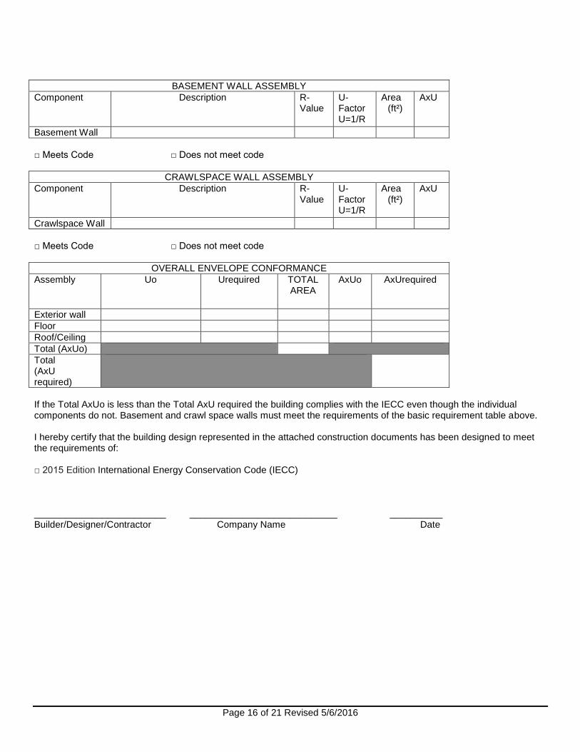
BASEMENT WALL ASSEMBLY
Component Description R-Value
U-Factor U=1/R
Area (ft²)
AxU
Basement Wall
□ Meets Code □ Does not meet code
CRAWLSPACE WALL ASSEMBLY
Component Description R-Value
U-Factor U=1/R
Area (ft²)
AxU
Crawlspace Wall
□ Meets Code □ Does not meet code
OVERALL ENVELOPE CONFORMANCE
Assembly Uo Urequired TOTAL AREA
AxUo AxUrequired
Exterior wall
Floor
Roof/Ceiling
Total (AxUo)
Total (AxU required)
If the Total AxUo is less than the Total AxU required the building complies with the IECC even though the individual components do not. Basement and crawl space walls must meet the requirements of the basic requirement table above. I hereby certify that the building design represented in the attached construction documents has been designed to meet the requirements of: □ 2015 Edition International Energy Conservation Code (IECC) _________________________ ____________________________ __________ Builder/Designer/Contractor Company Name Date
Page 17 of 21 Revised 5/6/2016
Method 2
Compliance with PERFORMANCE
REQUIREMENTS
R405 - SIMULATED PERFORMANCE ALTERNATIVE
The permit applicant shall submit documentation signed and sealed by a licensed design professional registered in Maryland, including:
1. Address of residence. 2. Permit number. 3. Analysis shall include heating, cooling and service water heating energy only. 4. All mandatory requirements of the 2015 IECC (Residential) shall be met. 3. Inspection checklist documenting the building component characteristics of the proposed design,
see Table R405.5.2(1) of IECC. 4. Accurate square footage 5. Mechanical system features. 6. Name of individual completing report. 7. Name and version of the compliance software tool. Approved compliance software: RemRate RemDesign Energy Gauge
Method 3 Compliance with Performance Requirements
SECTION R406
ENERGY RATING INDEX
COMPLIANCE ALTERNATIVE
R406.1 Scope. This section establishes criteria for compliance using an Energy Rating Index (ERI) analysis.
R406.2 Mandatory requirements. Compliance with this section requires that the mandatory provisions
identified in Sections R401.2 and R403.5.3 be met. The building thermal envelope shall be greater than or equal
to levels of efficiency and Solar Heat Gain Coefficient in Table 402.1.2 or 402.1.4 of the 2009 International
Energy Conservation Code.
Exception: Supply and return ducts not completely inside the building thermal envelope shall be insulated to a
The International Energy Conservation Code 2015 requires a Certificate, listing the energy conservation measures, be posted on a wall in the space where the furnace is located, a utility room or an approved location in the building at the time of the project’s final inspection.
A Certificate of Compliance is required anytime a building permit is issued with an Energy Compliance Form. Requirements for the certificate are listed in the code section below.
R401.3 Certificate (Mandatory). A permanent certificate shall be completed by the builder or registered design professional and posted on a wall in the space where the furnace is located, a utility room or an approved location inside the building. Where located on an electrical panel, the certificate shall not cover or obstruct the visibility of the circuit directory label, service disconnect label or other required labels. The certificate shall list the predominant R-values of insulation installed in or on ceiling/roof, walls, foundation (slab, basement wall, crawlspace wall and floor) and ducts outside conditioned spaces; U-factors for fenestration and the solar heat gain coefficient (SHGC) of fenestration, and the results from any required duct system and building envelope air leakage testing done on the building. Where there is more than one value for each component, the certificate shall list the value covering the largest area. The certificate shall list the types and efficiencies of heating, cooling and service water heating equipment. Where a gas-fired unvented room heater, electric furnace or baseboard electric heater is installed in the residence, the certificate shall list “gas-fired unvented room heater,” “electric furnace” or “baseboard electric heater,” as appropriate. An efficiency shall not be listed for gas-fired unvented room heaters, electric furnaces or electric baseboard heaters.
For the purpose of this Certificate, permanent shall mean: A type printed sticker, or a laminated printed paper; laminated certificates must be glued. The in-fill information is permitted to be handwritten under the categories of the printed certificate. Fully handwritten certificates shall not be allowed or deemed acceptable.
IECC 2015 Chapter 4, Section R401.3 Certificate
Page 21 of 21 Revised 5/6/2016
A sample printed Energy Efficiency Certificate is included above. You are free to use or copy this sample certificate, or, Energy Efficiency Certificate stickers can be purchased from the International Code Council Store.