Mini-Rester Mini-Rester ™ Residential Water Hammer Arrester • All Mini-Resters are approved for sealed wall installations with no access panel required • May be installed at any angle • AA size Listed by UPC/IAPMO to meet UPC-2009 Conforms to IPC-2009 Certified by ASSE to the ANSI/ASSE 1010-2004 Standard Indicated models comply with CA lead plumbing laws Seamless, cold rolled and spin closed Pressurized air cushion Dual o-ring piston
Transcript
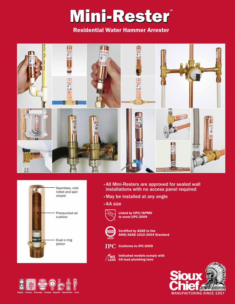
Mini-ResterMini-Rester™
Residential Water Hammer Arrester
• All Mini-Resters are approved for sealed wall installations with no access panel required
• May be installed at any angle• AA size
Listed by UPC/IAPMOto meet UPC-2009
Conforms to IPC-2009
Certified by ASSE to the ANSI/ASSE 1010-2004 Standard
Indicated models comply with CA lead plumbing laws
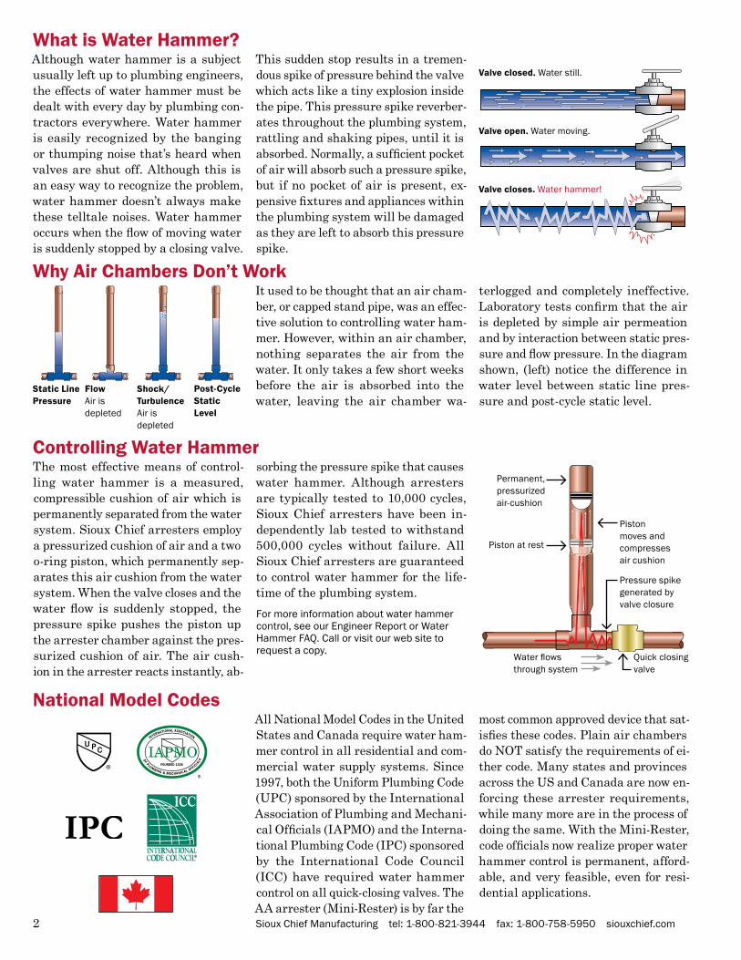
Although water hammer is a subject usually left up to plumbing engineers, the effects of water hammer must be dealt with every day by plumbing con-tractors everywhere. Water hammer is easily recognized by the banging or thumping noise that’s heard when valves are shut off. Although this is an easy way to recognize the problem, water hammer doesn’t always make these telltale noises. Water hammer occurs when the flow of moving water is suddenly stopped by a closing valve.
This sudden stop results in a tremen-dous spike of pressure behind the valve which acts like a tiny explosion inside the pipe. This pressure spike reverber-ates throughout the plumbing system, rattling and shaking pipes, until it is absorbed. Normally, a sufficient pocket of air will absorb such a pressure spike, but if no pocket of air is present, ex-pensive fixtures and appliances within the plumbing system will be damaged as they are left to absorb this pressure spike.
What is Water Hammer?
All National Model Codes in the United States and Canada require water ham-mer control in all residential and com-mercial water supply systems. Since 1997, both the Uniform Plumbing Code (UPC) sponsored by the International Association of Plumbing and Mechani-cal Officials (IAPMO) and the Interna-tional Plumbing Code (IPC) sponsored by the International Code Council (ICC) have required water hammer control on all quick-closing valves. The AA arrester (Mini-Rester) is by far the
most common approved device that sat-isfies these codes. Plain air chambers do NOT satisfy the requirements of ei-ther code. Many states and provinces across the US and Canada are now en-forcing these arrester requirements, while many more are in the process of doing the same. With the Mini-Rester, code officials now realize proper water hammer control is permanent, afford-able, and very feasible, even for resi-dential applications.
National Model Codes
Valve closed. Water still.
Valve open. Water moving.
Valve closes. Water hammer!
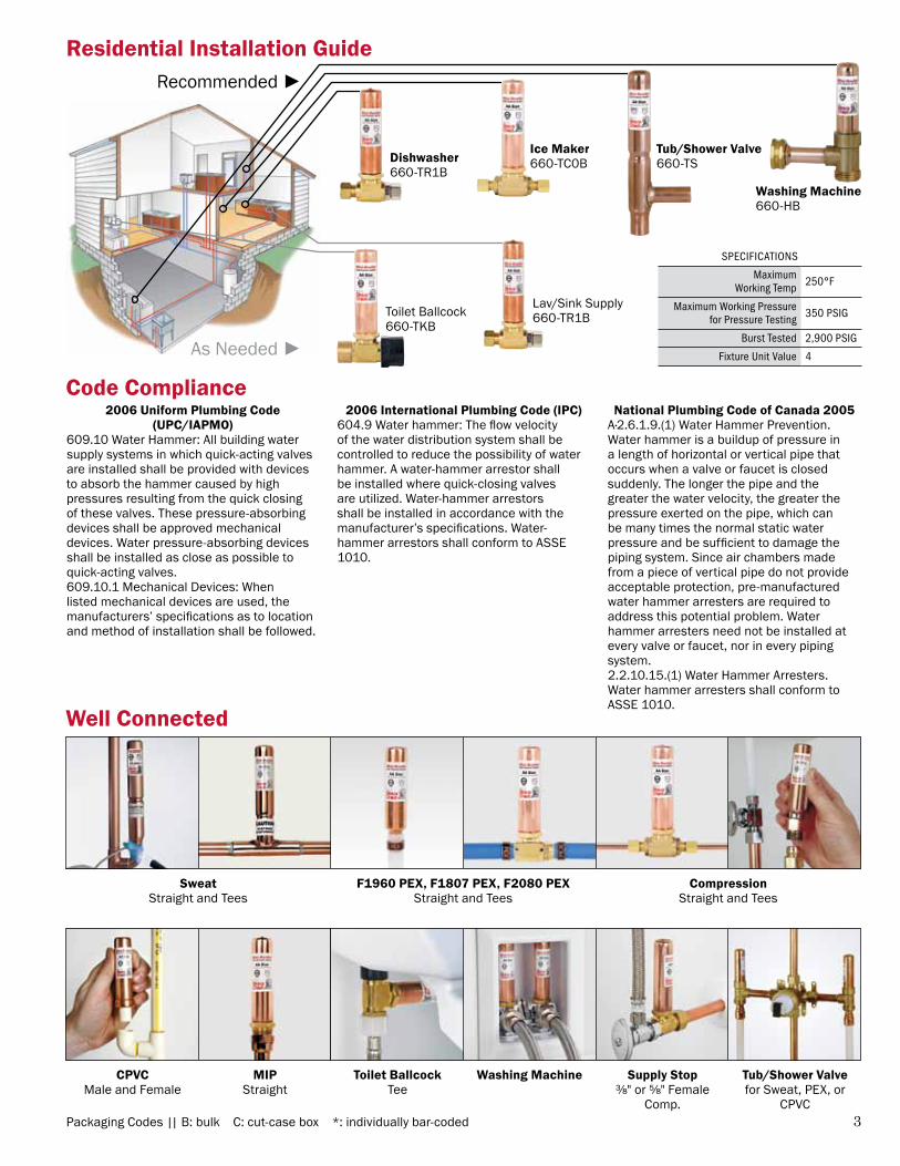
Why Air Chambers Don’t WorkIt used to be thought that an air cham-ber, or capped stand pipe, was an effec-tive solution to controlling water ham-mer. However, within an air chamber, nothing separates the air from the water. It only takes a few short weeks before the air is absorbed into the water, leaving the air chamber wa-
terlogged and completely ineffective. Laboratory tests confirm that the air is depleted by simple air permeation and by interaction between static pres-sure and flow pressure. In the diagram shown, (left) notice the difference in water level between static line pres-sure and post-cycle static level.
Static Line Pressure
Shock/TurbulenceAir is depleted
FlowAir is depleted
Post-Cycle Static Level
The most effective means of control-ling water hammer is a measured, compressible cushion of air which is permanently separated from the water system. Sioux Chief arresters employ a pressurized cushion of air and a two o-ring piston, which permanently sep-arates this air cushion from the water system. When the valve closes and the water flow is suddenly stopped, the pressure spike pushes the piston up the arrester chamber against the pres-surized cushion of air. The air cush-ion in the arrester reacts instantly, ab-
sorbing the pressure spike that causes water hammer. Although arresters are typically tested to 10,000 cycles, Sioux Chief arresters have been in-dependently lab tested to withstand 500,000 cycles without failure. All Sioux Chief arresters are guaranteed to control water hammer for the life-time of the plumbing system.
For more information about water hammer control, see our Engineer Report or Water Hammer FAQ. Call or visit our web site to request a copy.
Controlling Water HammerPermanent, pressurized air-cushion
Maximum Working pressure for pressure testing 350 pSiG
Burst tested 2,900 pSiG
fixture Unit Value 4
Ice Maker660-TC0B
Tub/Shower Valve660-TS
Toilet Ballcock660-TKB
Lav/Sink Supply660-TR1B
Dishwasher660-TR1B
Washing Machine660-HB
As Needed ►
Recommended ►
Code Compliance2006 Uniform Plumbing Code
(UPC/IAPMO)609.10 Water Hammer: All building water supply systems in which quick-acting valves are installed shall be provided with devices to absorb the hammer caused by high pressures resulting from the quick closing of these valves. These pressure-absorbing devices shall be approved mechanical devices. Water pressure-absorbing devices shall be installed as close as possible to quick-acting valves.609.10.1 Mechanical Devices: When listed mechanical devices are used, the manufacturers’ specifications as to location and method of installation shall be followed.
2006 International Plumbing Code (IPC)604.9 Water hammer: The flow velocity of the water distribution system shall be controlled to reduce the possibility of water hammer. A water-hammer arrestor shall be installed where quick-closing valves are utilized. Water-hammer arrestors shall be installed in accordance with the manufacturer’s specifications. Water-hammer arrestors shall conform to ASSE 1010.
National Plumbing Code of Canada 2005 A·2.6.1.9.(1) Water Hammer Prevention. Water hammer is a buildup of pressure in a length of horizontal or vertical pipe that occurs when a valve or faucet is closed suddenly. The longer the pipe and the greater the water velocity, the greater the pressure exerted on the pipe, which can be many times the normal static water pressure and be sufficient to damage the piping system. Since air chambers made from a piece of vertical pipe do not provide acceptable protection, pre-manufactured water hammer arresters are required to address this potential problem. Water hammer arresters need not be installed at every valve or faucet, nor in every piping system.2.2.10.15.(1) Water Hammer Arresters. Water hammer arresters shall conform to ASSE 1010.
Well Connected
SweatStraight and Tees
F1960 PEX, F1807 PEX, F2080 PEXStraight and Tees
CompressionStraight and Tees
CPVCMale and Female
MIPStraight
Toilet BallcockTee
Washing Machine Supply Stop⅜" or ⅝" Female
Comp.
Tub/Shower Valvefor Sweat, PEX, or
CPVC
24110 South Peculiar DrivePeculiar, Missouri 64078tel: 1-800-821-3944fax: 1-800-758-5950www.siouxchief.com
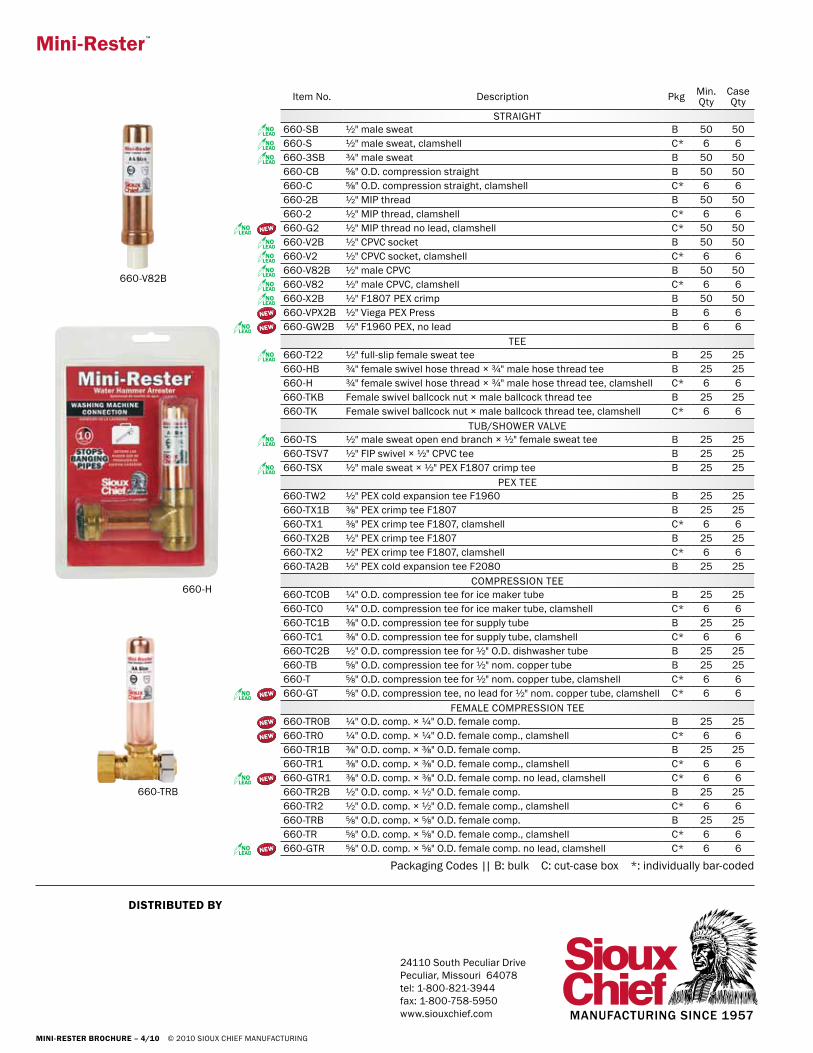
STRAIGHT660-SB ½" male sweat B 50 50660-S ½" male sweat, clamshell C* 6 6660-3SB ¾" male sweat B 50 50660-CB ⅝" O.D. compression straight B 50 50660-C ⅝" O.D. compression straight, clamshell C* 6 6660-2B ½" MIP thread B 50 50660-2 ½" MIP thread, clamshell C* 6 6660-G2 ½" MIP thread no lead, clamshell C* 50 50660-V2B ½" CPVC socket B 50 50660-V2 ½" CPVC socket, clamshell C* 6 6660-V82B ½" male CPVC B 50 50660-V82 ½" male CPVC, clamshell C* 6 6660-X2B ½" F1807 PEX crimp B 50 50660-VPX2B ½" Viega PEX Press B 6 6660-GW2B ½" F1960 PEX, no lead B 6 6
TEE660-T22 ½" full-slip female sweat tee B 25 25660-HB ¾" female swivel hose thread × ¾" male hose thread tee B 25 25660-H ¾" female swivel hose thread × ¾" male hose thread tee, clamshell C* 6 6660-TKB Female swivel ballcock nut × male ballcock thread tee B 25 25660-TK Female swivel ballcock nut × male ballcock thread tee, clamshell C* 6 6
TUB/SHOWER VALVE660-TS ½" male sweat open end branch × ½" female sweat tee B 25 25660-TSV7 ½" FIP swivel × ½" CPVC tee B 25 25660-TSX ½" male sweat × ½" PEX F1807 crimp tee B 25 25
PEX TEE660-TW2 ½" PEX cold expansion tee F1960 B 25 25660-TX1B ⅜" PEX crimp tee F1807 B 25 25660-TX1 ⅜" PEX crimp tee F1807, clamshell C* 6 6660-TX2B ½" PEX crimp tee F1807 B 25 25660-TX2 ½" PEX crimp tee F1807, clamshell C* 6 6660-TA2B ½" PEX cold expansion tee F2080 B 25 25
COMPRESSION TEE660-TC0B ¼" O.D. compression tee for ice maker tube B 25 25660-TC0 ¼" O.D. compression tee for ice maker tube, clamshell C* 6 6660-TC1B ⅜" O.D. compression tee for supply tube B 25 25660-TC1 ⅜" O.D. compression tee for supply tube, clamshell C* 6 6660-TC2B ½" O.D. compression tee for ½" O.D. dishwasher tube B 25 25660-TB ⅝" O.D. compression tee for ½" nom. copper tube B 25 25660-T ⅝" O.D. compression tee for ½" nom. copper tube, clamshell C* 6 6660-GT ⅝" O.D. compression tee, no lead for ½" nom. copper tube, clamshell C* 6 6