10 Transportation Research Record 919 Residual Soils of Piedmont and Blue Ridge GEORGE F. SOWERS AND THOMAS L. RICHARDSON The Piedmont and Blue Ridge form a band of crystalline rocks that extend from New Jersey southwest into Alabama. They are deeply and irregularly weathered into residual soils without appreciable transportation. The residual soils retain the mineral segregation; mineral alignment, and structural defects of the parent rocks. These are reflected in nonhomogeneous and anisotropic engineering properties. The soils inherit large residual stresses from the tee· tonically disturbed rock that are not related to overburden weight. They are stronger than their high void ratios imply. However, they exhibit localized surfaces of weakness that are responsible for excavation cave-ins and land- slides despite average strengths that indicate stability. Settlements due to imposed loads can be significant and nonuniform, particularly when the void ratios exceed 1.5. Settlements computed from ordinary consolidation theory usually exceed those observed, probably because of unknown residual stresses and pseudo'Preconsolidation. Initial settlements are large because the upper strata are partly saturated, hydrodynamic settlement is rapid, and secondary compression is often large because of the large mica content. The deeper horizons of residual soil (partly weathered rockl when loosened by ripping or blasting produce angular gravelly silty sands that are dense, strong, incom- pressible, and slow to drain when compacted. The more completely weath- ered residual soils produce sandy silts and silty sands. Their density and in- compressibility vary inversely with their mica content. The usual soil classi- fication systems (ASTM-Unified or AASHTOI are poor indexes to residual soil behavior. Instead, void ratio and defect characterization in undisturbed soil and mica content and compacted density in embankment materials are more reliable. The Piedmont and Blue Ridge provinces of the South- east compose the largest area in the United States underlain by residual soils derived from igneous and metamorphic rocks. These materials differ in their engineering properties from the commonly encountered traneported eande, eilta, and clays, Thua, the em- pirical correlations, design parameters, and mathe- matical models of conventional !'lni 1 mP.r.h;inf r.11 11re not always valid. Residual soils are the products of rock weather- ing that remain above the yet-to-be-weathered parent rock. Residual soils derived from igneous and meta- morphic rocks (except marble) retain much of the fabric and many of the structural features of the original rock. The degree of weathering decreases with increasing depth, usually with no well-defined boundary between soil and rock. Although the weath- ered materials have the texture of soils, they re- tain enough of the features of rock that their be- havior under load can often be modeled better by the methods of rock mechanics than by soil mechanics. In this paper the residual soils of the Piedmont and Blue Ridge of the Southeast are described and their engineering behavior as contrasted to trans- ported soils is summarized. PIEDMONT AND BLUE RIDGE The Piedmont and Blue Ridge are adjacent physio- graphic provinces that extend from Pennsylvania southwest into Alabama. They lie between the Atlan- tic Coastal Plain on the east and the Appalachian Ridge and Valley Province on the west (Figure 1) • Both are underlain by metamorphic rocks, predomi- nantly gneisses and schists, of early Paleozoic age or old!!r. Younger intrusive bodies of granite and similar silic rocks and occasional smaller bodies of mafic rocks, such as gabbro of late Paleozoic age, are scattered around. Numerous narrow disconnected dikes and occasional quartz-rich pegmatite bodies have been dated from early Mesozoic age. Although the rocks are similar, the last metamorphism of the Blue Ridge was probably more recent than that of the Piedmont. Within the Piedmont are some localized bodies of sandstones and mudstones of Triassic age. They accumulated in basins produced by downwarpinq and block faulting of the older metamorphic rocks. The Piedmont is a dissected, tilted plateau. The hilltops (the old plateau) range from elevation 300 m (1,000 ft) on the west to 100 to 150 m (300 to 500 ft) on the east. The relief is typically 30 to 60 m (100 - to 200 ft) with broad, sinuous hilltops and narrow zig-zag valleys. The Blue Ridge is higher, which reflects more recent (probably Triassic) up- lift with mountain tops at elevation 1000 to 2000 m (3,000 to 6,000 ft) and valleys between elevation 300 to 600 (1,000 to 2,000 ft). The Blue Ridge- Piedmont boundary is controversial. Some geologists define it by the Brevard Zone, a more-or-less con- tinuous band of sheared rocks more than a mile wide in Georgia and possibly a poorly defined fault in North Carolina and Virginia. Others define the boundary by the topography. The Piedmont hilltops seldom rise above elevation 300 m (1,000 ft) and re- tain the flatter tops of the old plateau. Rock Structure The regions have been subjected to numerous episodes of heat and pressure, which produced varying degrees of metamorphism. The major principal stress direc- tion was probably northwest, which reflects the forces of the crustal plate. The resulting folia- tion (the segregation of minerals) and orientation of minerals in p.arallel band11 re11emble stratifica- tion (and is sometimes so described) (Figure 2). However, the orientation of the foliation surfaces is related to the pressure and shear that produced metamorphism and not to any stratification of the unrnetamorphosed material. The foliation and banding are often contorted. In both regions the trend of the banding and foliation strikes northeast to southwest, the same as the regional trend of fold- ing. In the Piedmont the trend of the foliation dips is southeast. In the Blue Ridge the dips are far more irregular, which is a reflection of more intense folding and uplift. Usually several sets of joints result from dif- ferent episodes of structural deformation. In some areas the ioint orientations are uniform and are re- flected in zig-zag patterns of second- and third- order streams. In other areas the joints are ori- ented randomly. Joint spacings are also variable, although in some areas they alternate regularly be- tween close spacing and wide spacing. Figure 1. Location and idealized section of Piedmont and Blue Ridge.
Transcript
10 Transportation Research Record 919
Residual Soils of Piedmont and Blue Ridge
GEORGE F. SOWERS AND THOMAS L. RICHARDSON
The Piedmont and Blue Ridge form a band of crystalline rocks that extend from New Jersey southwest into Alabama. They are deeply and irregularly weathered into residual soils without appreciable transportation. The residual soils retain the mineral segregation; mineral alignment, and structural defects of the parent rocks. These are reflected in nonhomogeneous and anisotropic engineering properties. The soils inherit large residual stresses from the tee· tonically disturbed rock that are not related to overburden weight. They are stronger than their high void ratios imply. However, they exhibit localized surfaces of weakness that are responsible for excavation cave-ins and landslides despite average strengths that indicate stability. Settlements due to imposed loads can be significant and nonuniform, particularly when the void ratios exceed 1.5. Settlements computed from ordinary consolidation theory usually exceed those observed, probably because of unknown residual stresses and pseudo'Preconsolidation. Initial settlements are large because the upper strata are partly saturated, hydrodynamic settlement is rapid, and secondary compression is often large because of the large mica content. The deeper horizons of residual soil (partly weathered rockl when loosened by ripping or blasting produce angular gravelly silty sands that are dense, strong, incompressible, and slow to drain when compacted. The more completely weathered residual soils produce sandy silts and silty sands. Their density and incompressibility vary inversely with their mica content. The usual soil classification systems (ASTM-Unified or AASHTOI are poor indexes to residual soil behavior. Instead, void ratio and defect characterization in undisturbed soil and mica content and compacted density in embankment materials are more reliable.
The Piedmont and Blue Ridge provinces of the Southeast compose the largest area in the United States underlain by residual soils derived from igneous and metamorphic rocks. These materials differ in their engineering properties from the commonly encountered traneported eande, eilta, and clays, Thua, the empirical correlations, design parameters, and mathematical models of conventional !'lni 1 mP.r.h;inf r.11 11re not always valid.
Residual soils are the products of rock weathering that remain above the yet-to-be-weathered parent rock. Residual soils derived from igneous and metamorphic rocks (except marble) retain much of the fabric and many of the structural features of the original rock. The degree of weathering decreases with increasing depth, usually with no well-defined boundary between soil and rock. Although the weathered materials have the texture of soils, they retain enough of the features of rock that their behavior under load can often be modeled better by the methods of rock mechanics than by soil mechanics.
In this paper the residual soils of the Piedmont and Blue Ridge of the Southeast are described and their engineering behavior as contrasted to transported soils is summarized.
PIEDMONT AND BLUE RIDGE
The Piedmont and Blue Ridge are adjacent physiographic provinces that extend from Pennsylvania southwest into Alabama. They lie between the Atlantic Coastal Plain on the east and the Appalachian Ridge and Valley Province on the west (Figure 1) • Both are underlain by metamorphic rocks, predominantly gneisses and schists, of early Paleozoic age or old!!r. Younger intrusive bodies of granite and similar silic rocks and occasional smaller bodies of mafic rocks, such as gabbro of late Paleozoic age, are scattered around. Numerous narrow disconnected dikes and occasional quartz-rich pegmatite bodies have been dated from early Mesozoic age. Although the rocks are similar, the last metamorphism of the Blue Ridge was probably more recent than that of the Piedmont. Within the Piedmont are some localized
bodies of sandstones and mudstones of Triassic age. They accumulated in basins produced by downwarpinq and block faulting of the older metamorphic rocks.
The Piedmont is a dissected, tilted plateau. The hilltops (the old plateau) range from elevation 300 m (1,000 ft) on the west to 100 to 150 m (300 to 500 ft) on the east. The relief is typically 30 to 60 m (100 - to 200 ft) with broad, sinuous hilltops and narrow zig-zag valleys. The Blue Ridge is higher, which reflects more recent (probably Triassic) uplift with mountain tops at elevation 1000 to 2000 m (3,000 to 6,000 ft) and valleys between elevation 300 to 600 ~ (1,000 to 2,000 ft). The Blue RidgePiedmont boundary is controversial. Some geologists define it by the Brevard Zone, a more-or-less continuous band of sheared rocks more than a mile wide in Georgia and possibly a poorly defined fault in North Carolina and Virginia. Others define the boundary by the topography. The Piedmont hilltops seldom rise above elevation 300 m (1,000 ft) and retain the flatter tops of the old plateau.
Rock Structure
The regions have been subjected to numerous episodes of heat and pressure, which produced varying degrees of metamorphism. The major principal stress direction was probably northwest, which reflects the forces of the crustal plate. The resulting foliation (the segregation of minerals) and orientation of minerals in p.arallel band11 re11emble stratification (and is sometimes so described) (Figure 2). However, the orientation of the foliation surfaces is related to the pressure and shear that produced metamorphism and not to any stratification of the unrnetamorphosed material. The foliation and banding are often contorted. In both regions the trend of the banding and foliation strikes northeast to southwest, the same as the regional trend of folding. In the Piedmont the trend of the foliation dips is southeast. In the Blue Ridge the dips are far more irregular, which is a reflection of more intense folding and uplift.
Usually several sets of joints result from different episodes of structural deformation. In some areas the ioint orientations are uniform and are reflected in zig-zag patterns of second- and thirdorder streams. In other areas the joints are oriented randomly. Joint spacings are also variable, although in some areas they alternate regularly between close spacing and wide spacing.
Figure 1. Location and idealized section of Piedmont and Blue Ridge.
Transportation Research Record 919
Figure 2. Banded gneiss freshly exposed in presplit highway cut: top to bottom 3 ft.
Both regions are cut by numerous faults. Some are only tens of meters long and have displacements of less than a meter: others are many kilometers long and have undetermined displacements of hundreds of meters. Most of the faults are discrete fractures: however, a few are shear zones with crisscross fractures. Some faults near sensitive engineering structures have been dated by radioactive isotopes in minerals deposited in the fault surface. The minimum age is about 180 million years, which agrees with the geologic evidence of the most recent major tectonic thrusts.
Residual Tectonic Stresses
The crustal thrusts that produced the metamorphism, folding, and shears of the regions have not all been dissipated by the structural displacements. A few in situ rock stress tests have shown that the horizontal stresses at depths as great as 300 m (l,000 ft) exceed the vertical stresses due to rock weight. The major principal stresses trend northwest to southeast, the same direction as the regional thrusts. These residual stresses are sometimes relieved by erosion, accompanied by opening of the joints or slipping along foliation surfaces in the stress-relieved rock.
RESIDUAL SOIL FORMATION
Residual soils in the region are the products of the chemical decomposition of the various complex aluminum silicate minerals of the original rock. The products are clay minerals, hydrous micas, iron oxides, and semisoluble carbonates and bicarbonates. The temperate-to-warm climate, abundant rain [more than 750 mm (30 in.) per year] and well-established vegetation have been favorable to rapid weathering; the distribution of rain through the year, the vegetation, and the lack of glaciation have been favorable to accumulating the weathering products. Mechanical weathering of the rock is minimal because of the moderate climate and protection of the rock by vegetation on all but the highest, steepest mountains or stream channels.
Volume change is probably associated with weathering. Weathering of the aluminum silicates allows a stressed rigid quartz framework to distort. The geochemical changes of weathering produce volume changes: their effect on the volume of the residual soil compared with the original rock is not known.
11
Saprolite
When the weathering is accompanied by small volume changes the original fabric (arrangement of minerals) in the rock and most defects are retained. Such residual so~ls are termed saprolites. If large volume changes occur, such as in the solution of carbonate rocks where only the insoluble impurities remain, little or none of the parent rock's fabric is reflected in the residual soil.
On sloping terrain gravity and the volume changes due to weathering distort and even displace the residual soil. With sufficient movement the saprolite structure is destroyed, and the soil is then a form of colluvium with blocks of saprolite floating in a matrix of sandy silt and silty sands. If the movements are small and creep-like, the saprolite destruction becomes less with increasing depth,
Weathering Profile
Typical weathering profiles are shown in Figure 3, and examples of saprolite weathering are shown in Figures 4-6. The weathering is most advanced at the ground surface and decreases with increasing depth. Four zones can be identified:
l. Upper zone--completely weathered with welldeveloped pedologic horizons,
2. Intermediate zone--saprolite with soil texture but retains relict structure of the original rock,
3. Partly weathered zone--alternate seams of saprolite and less-weathered rock, and
4. Unaltered or slightly weathered rock.
Figure 3. Weathering profile of crystalline ro_cks in humid temperate region.
iiEi.i;rlvii,: SOUND ROCK ZONES
Figure 4. Saprolite from gneiss exposed in footing excavation.
12
Figure 5. Saprolite and partly weathered zone from granite exposed in highway cut.
Figure 6. Saprolite from gneiss showing fault displacement of parent rock.
The boundaries of the zones are not well-defined; the transition from one to the other is usually gradual. The boundaries are not horizontal. The weathering is deeper and more advanced adjacent to fractures that transmit water and in mineral bands that are more susceptible to decomposition. As a result the soil depth can be irregular, as shown in Figure 3. Variations in soil depth, as reflected by differences in end bearing pile length, of 3 m (10 ft) in a horizontal distance of 3 m are not unusual. Variations in residual soil of 20 m (75 ft) within a city block are not unusual. The variations are greatest in rocks that have steeply dipping foliation.
The upper zone exhibits a humid, temperate region pedologic profile with a leached, somewhat sandy A horizon and a more clayey and oxidized B horizon. The clays are kaolinitic over granites, gneisses, and most schists. The clays are mixed kaolinitesmectite (montmorillonite) over mafic intrusions and dikes.
The saprolite zone exhibits weathering of the feldspar and ferromagnesian minerals into clays and clay .... like minerals but retains much of the mica and all the quartz unweathered. In saprolites derived from granite weathering proceeds downward and inward from cracks more or less uniformly. The result is
Transportation Research Record 919
an XX pattern, as shown in Figure 3b and 5, that has boulder-like less weathered rock between the cracks. The boulders have an onion structure and the degree of weathering becomes less toward the boulder center.
In saprolites derived from gneisses and schists the weathering pattern is dominated by the mineral segregation in bands (Figures 4 and 6). The saprolite exhibits brightly colored bands, which reflect the varying amounts and degrees of oxidation of the iron oxides. Depending on scale, the banding represents either anisotropy or nonhomogeneity. On a small scale the foliation produces anisotropy in the orientation of minerals, particularly the micas, parallel to the banding. In the saproli te the unweathered quartz, mica, and the incompletely weathered feldspars retain the same position and orientation as in the original rock, including interlocking and molecular bonding. Volume changes that accompany weathering destroy some but not all of the interparticle bonds. Thus, residual stresses from tectonic loading and previous overburden that has eroded away are partly retained in the saprolite fabric. These residual stresses are modified by the volume changes that accompany mineral decomposition.
The depth of the intermediate zone varies greatly in the Piedmont and Blue Ridge. The greatest depth we have measured is 35 m ( 120 ft) i depths of 60 m (200 ft) have been inferred from caisson construction in Atlanta.
The partly weathered zone reflects the different rates of weathering of the different rock bands. Seams of hard, relatively unweathered rock alternate with seams of more-weathered saprolite. In the weathered rock zones the soils are coarser grained than in the saprolite, which reflects the lesser weathering. Inward weathering from joints in the harder seams produces deep soft senmR ~R WPll nR thP boulder-like bodies seen in Figure 5. The partly weathered zone thickness is variable, It is greatest in gneisses with strongly contrasting wide mineral bands and in rocks where the joint spacing is wide: 1 to 3 m (3 to 10 ft).
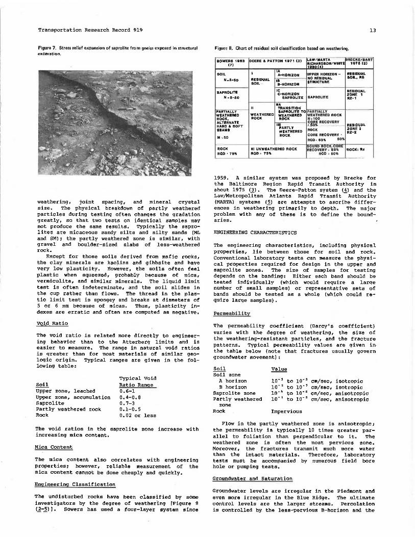
Slickensides
Many saprolites contain slickensided surfaces that cannot be traced to faults in the rock below. These surfaces are plane to curved, often dipping at angles between 40° and 70°. Their origin is in dispute. We conclude that they develop from stress-relief expansion as the weathering process proceeds (Figure 7). Some are coated with a waxy black mineral. Microtests show the black substance to be an iron-manganese-organic complex. The substance probably leached into the crack from the topsoil above <..!.> •
CLASSIFICATION
The common soil classification systems, Unified-ASTM and AASHTO, have limited application to residual soils. They can reflect the engineering behavior of the upper soil zone where the weathering is virtually complete. However, in the much thicker saprolite and partly weathered zones the relic structure of the rock and the changing physical properties that accompany incomplete weathering are not reflected in the index tests that are the basis for classification.
Texture
The texture of the saprolites and partly weathered zone ranges from boulder to clay sizes. The gradations are often irregular because of variations in
Transportation Research Record 919
Figure 7. Stress relief expansion of saprolite from gneiss exposed in structural excavation.
weathering, joint spacing, and mineral crystal size. The physical breakdown of partly weathered particles during testing often changes the gradation greatly, so that two tests on identical samples may not produce the same results. Typically the saprolites are micaceous sandy silts and silty sands (ML and SM) 1 the partly weathered zone is similar, with gravel and boulder-sized slabs of less-weathered rock.
Except for those soils derived from mafic rocks, the clay minerals are kao;I.ins and gibbsite and have very low plasticity. However, the soils often feel plastic when squeezed, probably because of mica, vermiculite, and similar minerals. The liquid limit test is often indeterminate, and the soil slides in the cup rather than flows. The thread in the plastic limit test is spongey and breaks at diameters of 5 or 6 mm because of micas. Thus, plasticity indexes are erratic and often are computed as negative.
Void Ratio
The void ratio is related more directly to engineering behavior than to the Atterberg limits and is easier to measure. The range in natural void ratios is greater than for most materials of similar geologic origin. Typical ranges are given in the following table:
Soil Upper zone, leached Upper zone, accumulation Saprolite Partly weathered rock Rock
Typical Void Ratio Range 0.6-1 0.4-0.8 0.7-3 0.1-0.5 0.02 or less
The void ratios in the saprolite zone increase with increasing mica content.
Mica Content
The mica content also correlates with engineering properties1 however, reliable measurement of the mica content cannot be done cheaply and quickly.
Engineering Classification
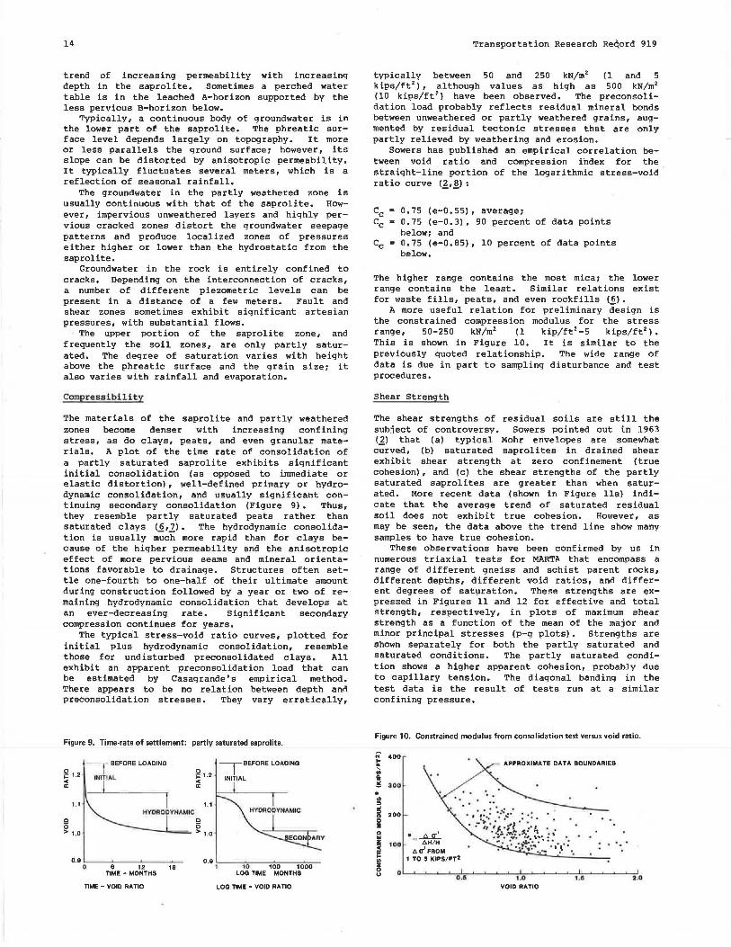
The undisturbed rocks have been classified by some investigators by the degree of weathering [Figure 8 !1-2>). Sowers has used a four-layer system since
13
Figure 8. Chart of residual soil classification based on weathering.
UPPER HORIZON - RESIDUAL BOIL A-HORIZON NO Re&IDUAL llOIL, Ill
N.5-50 RESIDUAL IB STRUCTURE BOIL • &-HORIZON
BAPROLITE IC RESIDUAL C-HORIZON ZONll! 1
N ·5-50 BA PRO LITE SAPROLITE RZ-1
HA II TRANSITION
PARTIALLY 8APROLITE TO PARTIALLY WEATHERED WEATHERED WEATHERED WEATHa!l!D ROCK ROCK, ROCK ROCK N.100 ALTERNATE
118 C9M RECOVERY
RESIDUAL HARD a llOFT PARTLY ZONll! 2 lll!AM8 WEATHERED ROCK RZ-2
ROCK CORE RECOVERY > N ,50
ROD< 50" 5011>
ROCK Ill UNWEATHERED ROCK ~v\JNU ""'"°" ' """"'"-~ RECOVeRY • 11511> ROCK: Rx
ROD> 75 .. ROD> 7511> ROD> 50" -
1959. A similar system was proposed by Brecke for the Baltimore Region Rapid Transit Authority in about 1975 (3). The Deere-Patton system (4) and the Law/Metropolitan Atlanta Rapid Transit -Authority (MARTA) systems (5) are attempts to ascribe differences in weatheri~g primarily to depth. The major problem with any of these is to define the boundaries.
ENGINEERING CHARACTERISTICS
The engineering characteristics, including physical properties, lie between those for soil and rock. Conventional laboratory tests can measure the physical properties required for design in the upper and saprolite zones. The size of samples for testing depends on the banding: Either each band should be tested individually (which would require a large number of small samples) or representative sets of bands should be tested as a whole (which could require large samples).
Permeability
The permeability coefficient (Darcy's coefficient) varies with the degree of weathering, the size of the weathering-resistant particles, and the fracture patterns. Typical permeability values are given in the table below (note that fractures usually govern groundwater movement) :
Soil Soil zone
A horizon B horizon
Saprolite zone Partly weathered
zone Rock
Value
10 - 3 to lo-• cm/sec, isotropic lo - • to 10- 7 cm/sec, isotropic 10-~ to lo-• cm/sec, anisotropic 10 - 1 to lo-• cm/sec, anisotropic
Impervious
Flow in the partly weathered zone is anisotropici the permeability is typically 10 times greater parallel to foliation than perpendicular to it. The weathered zone is often the most pervious zone. Moreover, the fractures transmit much more water than the intact materials. Therefore, laboratory tests must be accompanied by numerous field bore hole or pumping tests.
Groundwater and Saturation
Groundwater levels are irregular in the Piedmont and even more irregular in the Blue Ridge. The ultimate control levels are the larger streams. Percolation is controlled by the less-pervious B-horizon and the
14
trend of increasing permeability with increasing depth in the saprolite. Sometimes a perched water table is in the leached A-horizon supported by the less pervious B-horizon below.
Typically, a continuous body of groundwater is in the lower part of the saprolite. The phreatic surface level depends largely on topography. It more or less parallels the ground surfacei however, its slope can be distorted by anisotropic permeability. It typically fluctuates several meters, which is a reflection of seasonal rainfall.
The groundwater in the partly weathered zone is usually continuous with that of the saprolite. However, impervious unweathered layers and highly pervious cracked zones distort the groundwater seepage patterns and produce localized zones of pressures either higher or lower than the hydrostatic from the saprolite.
Groundwater in the rock is entirely confined to cracks. Depending on the interconnection of cracks, a number of different piezometric levels can be present in a distance of a few meters. Fault and shear zones sometimes exhibit significant artesian pressures, with substantial flows.
The upper portion of the saprolite zone, and frequently the soil zones, are only partly saturated. The degree of saturation varies with height above the phreatic surface and the grain sizei it also varies with rainfall and evaporation.
Compressi bility
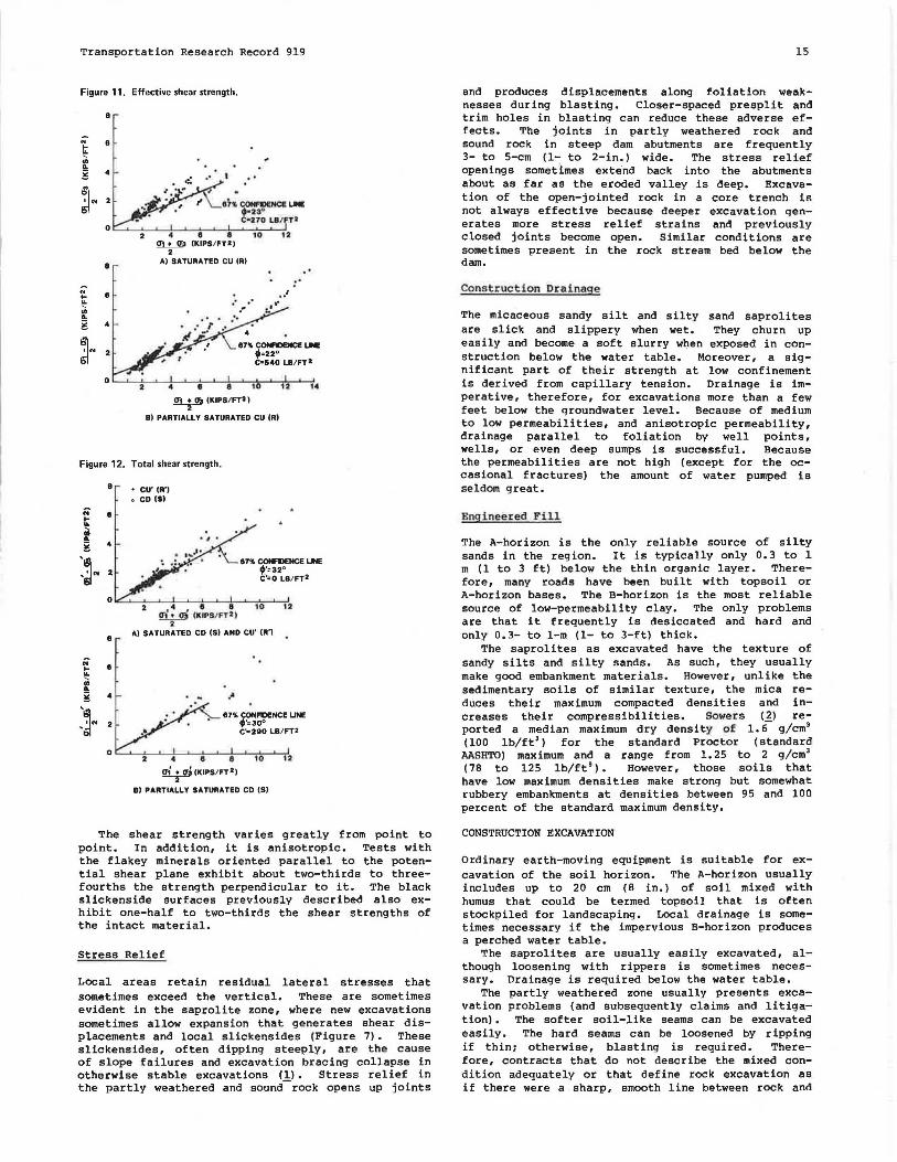
The materials of the saprolite and partly weathered zones become denser with increasing confining stress, as do clays, peats, and even granular materials. A plot of the time rate of consolidation of a partly saturated saprolite exhibits significant initial consolidation (as opposed to immediate or elastic distortion), well-defined primary or hydrodynamic consolidation, and usually significant continuing secondary consolidation (Figure 9). Thus, they resemble partly saturated peats rather than saturated clays (6,7). The hydrodynamic consolidation is usually m-;ic"h more rapid than for clays because of the higher permeability and the anisotropic effect of more pervious seams and mineral orientations favorable to drainage. Structures often settle one-fourth to one-half of their ultimate amount during construction followed by a year or two of remaining hydrodynamic consolidation that develops at an ever-decreasing rate. Significant secondary compression continues for years.
The typical stress-void ratio curves, plotted for initial plus hydrodynamic consolidation, resemble those for undisturbed preconsolidated clays. All exhibit an apparent preconsolidation load that can be estimated by Casagrande' s empirical method. There appears to be no relation between depth and preconsolidation stresses. They vary erratically,
Figure 9. Time-rate of settlement: partly saturated saprolite.
typically between 50 and 250 kN/m 2 (1 and 5 kips/ft 2
), although values as high as 500 kN/m 2
(10 kips/ft'! have been observed. The preconsolidation load probably reflects residual mineral bonds between unweathered or partly weathered grains, augmented by residual tectonic stresses that are only partly relieved by weathering and erosion.
Sowers has published an empirical correlation between void ratio and compression index for the straight-line portion of the logarithmic stress-void ratio curve (_£,~) :
Cc 0.75 (e-0.55), averagei Cc 0.75 (e-0.3), 90 percent of data points
belowi and Cc 0.75 (e-0.85), 10 percent of data points
below.
The higher range contains the most micai the lower range contains the least. Similar relations exist for waste fills, peats, and even rockfills (6).
A more useful relation for preliminary design is the constrained compression modulus for the stress range, 50-250 kN/m2 (1 kip/ft 2 -5 kips/ft2
).
This is shown in Figure 10. It is similar to the previously quoted relationship. The wide range of data is due in part to sampling disturbance and test procedures.
Shear Strength
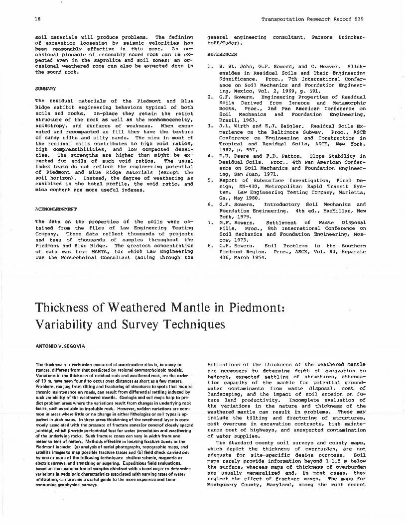
The shear strengths of residual soils are still the subject of controversy. Sowers pointed out in 1963 (_£) that (a) typical Mohr envelopes are somewhat curved, (b) saturated saprolites in drained shear exhibit shear strength at zero confinement (true cohesion), and (c) the shear strengths of the partly saturated saprolites are greater than when saturated. More recent data (shown in Figure lla) indicate that the average trend of saturated residual soil does not exhibit true cohesion. However, as may be seen, the data above the trend line show many samples to have true cohesion.
These observations have been confirmed by us in numerous triaxial tests for MARTA that encompass a range of different gneiss and schist parent rocks, different depths, different void ratios, and different degrees of saturation. These strengths are expressed in Figures 11 and 12 for effective and total strength, respectively, in plots of maximum shear strength as a function of the mean of the major and minor principal stresses (p-q plots). Strengths are shown separately for both the partly saturated and saturated conditions. The partly saturated condition shows a higher apparent cohesion, probably due to capillary tension. The diagonal banding in the test data is the result of tests run at a similar confining pressure.
Figure 10. Constrained modulus from consolidation test versus void ratio.
N 400
~ le g 300
• .. :::> ...l
5 200 0 :I Q w ~ 100 · =~ 6H/H
60-' FROM 1 TO 5 KIPS/FT•
APPROXIMATE DATA BOUNDARIES
i o~_.__._~_.__,,...=---'~'-..__.__.,,_._~~~~_.,,_~~~~___,
0.5 1,0 1.8 2.0 VOID RATIO
Transportation Research Record 919
Figure 11. Effective shear strength.
8
~ 8
"' .. g 4 .. .. ~N ah.~LM •23°
• 270 UI/ '2 0
4 8 8 10 ·12 Cf!• Cf3 (KIPSI FT2)
2
8 A) SATURATED CU IR)
" : . " 8 t .. .. ~
"' .. g 4
~N 87" CONfllENCE ~ f=22° C•540 LB/FT2
0 4 8 8 10 12 , .. ~ (KIPS/ FT2)
B) PARTIALLY SATURATED CU (R)
Figure 12. Total shear strength .
8
8
• cu· (A'l • CD (S)
87% CONR>ENCE UNE f'=32° C'=O L8/ FT2
o i.::::....__.__.__i.~__,.__._4--~_.__.__,
.• , e e 10 12
8
!!l.!...2) (KIP8/ FT2 ) 2
A) SATURATED CD (S) AND CU' (R')
·" 87% CONFllENCE UNE
;·.30° C'o290 LB/FT2
. . a, 2 Cfo IKIPS/ FT 2l
B) PARTIALLY SATURATED CD (S)
The shear strength varies greatly from point to point. In addition, it is anisotropic. Tests with the flakey minerals oriented parallel to the potential shear plane exhibit about two-thirds to threefourths the strength perpendicular to it. The black slickenside surfaces previously described also exhibit one-half to two-thirds the shear strengths of the intact material.
Stress Relief
Local areas retain residual lateral stresses that sometimes exceed the vertical. These are sometimes evident in the saprolite zone, where new excavations sometimes allow expansion that generates shear displacements and local slickensides (Figure 7). These slickensides, often dipping steeply, are the cause of slope failures and excavation bracing collapse in otherwise stable excavations (1). Stress relief in the partly weathered and sound-rock opens up joints
15
and produces displacements along foliation weaknesses during blasting. Closer-spaced presplit and trim holes in blasting can reduce these adverse effects. The joints in partly weathered rock and sound rock in steep dam abutments are frequently 3- to 5-cm ( 1- to 2-in.) wide. The stress relief openings sometimes extend back into the abutments about as far as the eroded valley is deep. Excavation of the open-jointed rock in a core trench is not always effective because deeper excavation generates more stress relief strains and previously closed joints become open. Similar conditions are sometimes present in the rock stream bed below the dam.
Const ruction Drainage
The micaceous sandy silt and s i lty sand saprolites are slick and slippery when wet. They churn up easily and become a soft slurry when exposed in construction below the water table. Moreover, a significant part of their strength at low confinement is derived from capillary tension. Drainage is imperative, therefore, for excavations more than a few feet below the groundwater level. Because of medium to low permeabilities, and anisotropic permeability, drainage parallel to foliation by well points, wells, or even deep sumps is successful. Because the permeabilities are not high (except for the occasional fractures) the amount of water pumped is seldom great.
Enginee red Fill
The A-horizon is the only reliable source of silty sands in the reg ion. It is typically only 0. 3 to 1 m (1 to 3 ft) below the thin organic layer. Therefore, many roads have been built with topsoil or A-horizon bases. The B-horizon is the most reliable source of low-permeability clay. The only problems are that it frequently is desiccated and hard and only 0.3- to 1-m (1- to 3-ft) thick.
The saprolites as excavated have the texture of sandy silts and silty sands. As such, they usually make good embankment materials. However, unlike the sedimentary soils of similar texture, the mica reduces their maximum compacted densities and increases their compressibilities. Sowe r s (2) reported a median maximum dry density o f 1. 6- g/cm3
(100 lb/ft3) for the standard Proctor (standard
AASHTO) maximum and a range from 1. 25 to 2 g/cm• (78 to 125 lb/ft'). However, those soils that have low maximum densities make strong but somewhat rubbery embankments at densities between 95 and 100 percent of the standard maximum density.
CONSTRUCTION EXCAVATION
Ordinary earth-moving equ i pment is suitable for excavation of the soil horizon. The A-horizon usually includes up to 20 cm (8 in.) of soil mixed with humus that could be termed topsoil that is often stockpiled for landscaping. Local drainage is sometimes necessary if the impervious B-horizon produces a perched water table.
The saprolites are usually easily excavated, although loosening with rippers is sometimes necessary. Drainage is required below the water table.
The partly weathered zone usually presents excavation problems (and subsequently claims and litigation). The softer soil-like seams can be excavated easily. The hard seams can be loosened by ripping if thin; otherwise, blasting is required. Therefore, contracts that do not describe the mixed condition adequately or that define rock excavation as if there were a sharp, smooth line between rock and
16
soil materials will produce problems. The defining of excavation loosening by seismic velocities has been reasonably effective in this zone. An occasional pinnacle of resonably sound rock can be expected even in the saprolite and soil zones 1 an occasional weathered zone can also be expected deep in the sound rock.
SUMMARY
The residual materials of the Piedmont and Blue Ridge exhibit engineering behaviors typical of both soils and rocks. In-place they retain the relict structure of the rock as well as the nonhomogeneity, anisotropy, and surfaces of weakness. When excavated and recompacted as fill they have the texture of sandy silts and silty sands. The mica in most of the residual soils contributes to high void ratios, high compressibilities, and low compacted densities. The strengths are higher than might be expected for soils of such void ratios. The usual index tests do not reflect the engineering potential of Piedmont and Blue Ridge materials (except the soil horizon). Instead, the degree of weathering as exhibited in the total profile, the void ratio, and mica content are more useful indexes.
ACKNOWLEDGMENT
The data on the properties of the soils were obtained from the files of Law Engineering Testing Company. These data reflect thousands of projects and tens of thousands of samples throughout the Piedmont and Blue Ridge. The greatest concentration of data was from MARTA, for which Law Engineering was the Geotechnical Consultant (acting through the
Transportation Research Record 919
general engineering consultant, Parsons Brinckerhoff/Tudor).
REFERENCES
1. B. St. John, G.F. Sowers, and c. Weaver. Slickensides in Residual Soils and Their Engineering Significance. Proc., 7th International Conference on Soil Mechanics and Foundation Engineering, Mexico, Vol. 2, 1969, p. 591.
2. G.F. Sowers. Engineering Properties of Residual Soils Derived from Igneous and Metamorphic Rocks. Proc., 2nd Pan American Conference on Soil Mechanics and Foundation Engineering, Brazil, 1963.
3. J.L. Wirth and E.J, Zeigler. Residual Soils Experience on the Baltimore Subway. Proc., ASCE Conference on Engineering and Construction in Tropical and Residual Soils, ASCE, New York, 1982, p. 557.
4. D.U. Deere and F.D. Patton. Slope Stability in Residual Soils. Proc., 4th Pan American Conference on Soil Mechanics and Foundation Engineering, San Juan, 1971.
5. Report of Subsurface Investigation, Final Design, DN-430, Metropolitan Rapid Transit System. Law Engineering Testing Company, Marietta, Ga., May 1980.
6. G.F. Sowers. Introductory Soil Mechanics and Foundation Engineering. 4th ed., MacMillan, New York, 1979.
7. G.F. Sowers. Settlement of Waste Disposal Fills. Proc., Bth International Conference on Soil Mechanics and Foundation Engineering, Moscow, 1973.
B. G.F. Sowers. Soil Problems in the Southern Piedmont Region. Proc., ASCE, Vol. BO, Separate 416, March 1954.
Thickness of Weathered Mantle in Piedmont: Variability and Survey Techniques
ANTONIO V. SEGOVIA
The thickness of overburden measured at construction sites is, in many in· stances, different from that predicted by regional geomorphologic models. Variations in the thickness of residual soils and weathered rock, on the order of 10 m, have been found to occur over distances as short as a few meters. Problems, ranging from tilting and fracturing of structures to spots that require chronic maintenance on roads, can result from differential settling induced by such variability of the weathered mantle. Geologic and soil maps help to pre· diet problem areas where the variations result from changes in underlying rock facies, such as soluble to insoluble rock. However, sudden variations are common in areas where little or no change in either lithologies or soil types is apparent in such maps. In these areas thickening of the weathered layer is commonly associated with the presence of fracture zones (or zones of closely spaced jointing), which provide preferential loci for water percolation and weathering of the underlying rocks. Such fracture zones can vary in width from one meter to tens of meters. Methods effective in locating fracture zones in the Piedmont include: (al an.alysis of aerial photographs, topographic maps, and satellite images to map possible fracture traces and (bl field check carried out by one or more of the following techniques: shallow seismic, magnetic or electric surveys, and trenching or augering. Expeditious field evaluations, based on the examination of samples obtained with a hand auger to determine variations in pedologic characteristics associated with varying rates of water infiltration, can provide a useful guide to the more expensive and time-consu ming geophysical surveys.
Estimations of the thickness of the weathered mantle are necessary to determine depth of excavation to bedrock, expected settling of structures, attenuation capacity of the mantle for potential groundwater contaminants from waste disposal, cost of landscaping, and the impact of soil erosion on future land productivity. Incomplete evaluation of the variations in the nature and thickness of the weathered mantle can result in problems. These may include the tilting and fracturing of structures, cost overruns in excavation contracts, high maintenance cost of highways, and unexpected contamination of water supplies.
The standard county soil surveys and county maps, which depict the thickness of overburden, are not adequate for site-specific design purposes. Soil maps rarely provide information beyond 1-1.5 m below the surface, whereas maps of thickness of overburden are usually generalized and, in most cases, they neglect the effect of fracture zones. The maps for Montgomery County, Maryland, among the most recent