14
Resistive Effects in Ceramic Kicker Chamber. Roughness Effects in Undulator Chamber. Andranik Tsakanian, Uni Hamburg DESY, 16 April 2007
| Date post: | 02-Jan-2016 |
| Category: |
Documents |
| Upload: | rose-harmon |
| View: | 32 times |
| Download: | 0 times |

Resistive Effects in Ceramic Kicker Chamber.Roughness Effects in Undulator Chamber.
Andranik Tsakanian,
Uni Hamburg
DESY, 16 April 2007
Topics
• Impedance Structure Investigation for Ceramic Kicker Vacuum
Chamber with metallic coats.
• Resistive and Geometrical Wakes.
• Influence of Surface Roughness in Undulator Chamber on
the Beam.
DESY, 16 April 2007

DESY, 16 April 2007
Impedance Structure Investigation of Ceramic Kicker Vacuum
Chamber with Metallic Coats.
M. Ivanyan, V. Tsakanov, Phys. Rev. ST-AB, 2004
kU
jZkZ
0
342334233443
342334233443
03
3222 2
aRaRaSaR
aRaRaSaRaaU
- combination of Bessel functions.SSRR ,,,
Single layer cylindrical tube
aKbIaIbK
aKbIaIbKaaU
0000
1010
0
2 2
Longitudinal Impedance. Monopole term.
ii j0 ii j 0
1a/ ii
4433
4433
30
32 12
dthdth
dthdthaaU
2/1
43
1
dctha
aU
0
2 2
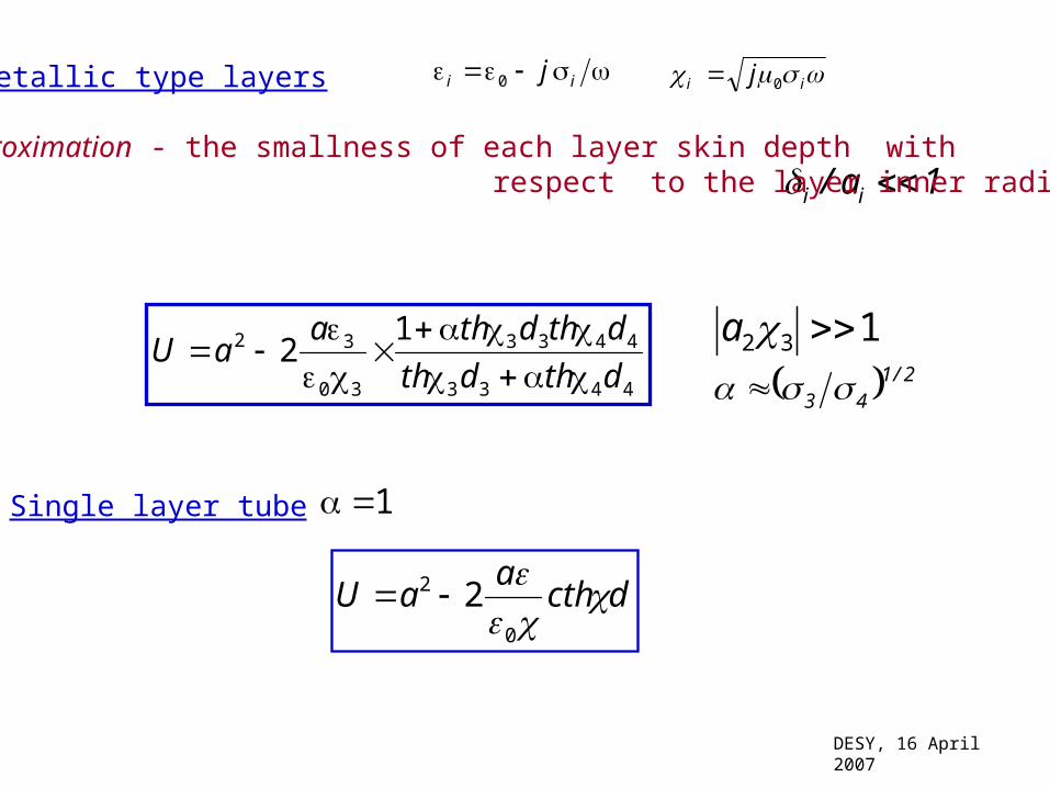
Metallic type layers
Good approximation - the smallness of each layer skin depth with respect to the layer inner radius
Single layer tube
132 a
DESY, 16 April 2007

)()(
)()(12
433
433
30
32
dnkthjdth
dnkthdthjaaU
Ceramic type layers with metallic coats
Good approximation:
Actually for all the practical applications, the formula (*) is valid and well approximates the exact solution.
204 n 12
4 njk143 a
132 a
ldnkdtha
aU
ldnkdctha
aU
2)(2
)(2
43330
32
43330
32
ckj 03 kjc 03 Metallic layer
Ceramic layer
4
3
3
4
12 nn
Nl
*
DESY, 16 April 2007
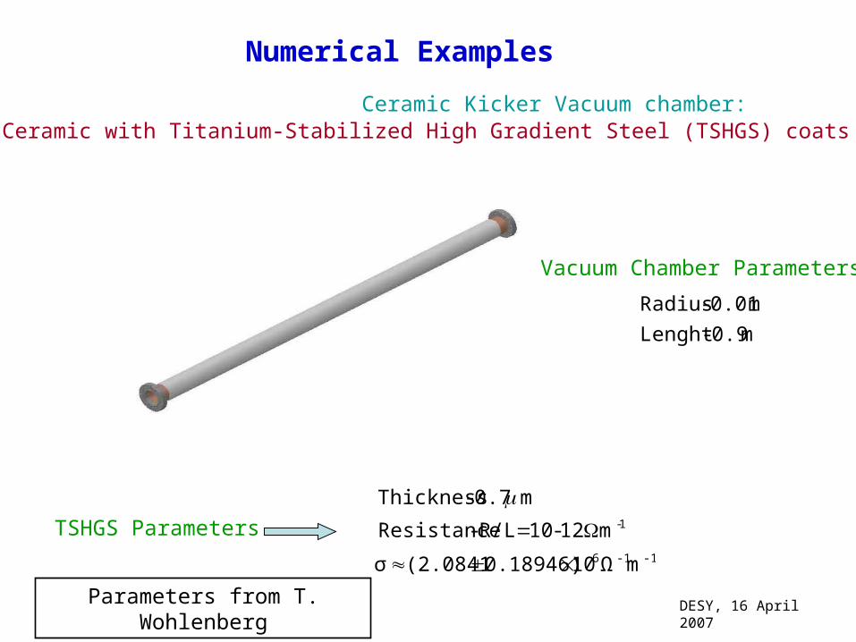
Numerical Examples
Ceramic Kicker Vacuum chamber: Ceramic with Titanium-Stabilized High Gradient Steel (TSHGS) coats
m 0.9 -Lenght
m 0.01 - Radius
1-m 12-10 R/L - Resistance
m 0.7 - Thickness
-1-16 mΩ100.18946)(2.0841σ
TSHGS Parameters
Vacuum Chamber Parameters
DESY, 16 April 2007Parameters from T. Wohlenberg
DESY, 16 April 2007
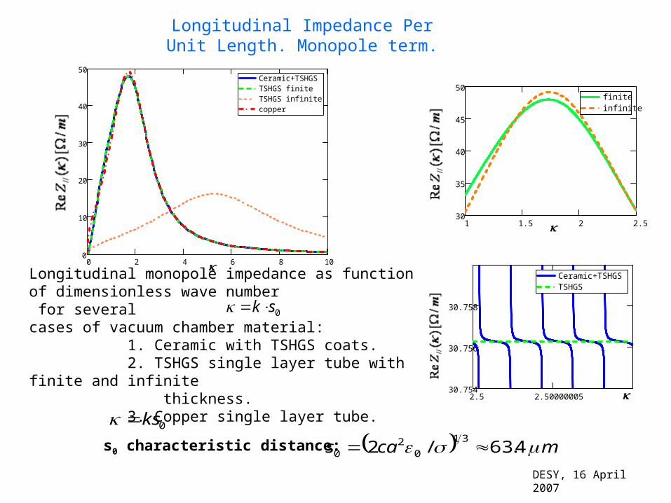
Longitudinal Impedance Per Unit Length. Monopole term.
0 2 4 6 8 100
10
20
30
40
50Ceramic+TSHGSTSHGS finiteTSHGS infinitecopper
Longitudinal monopole impedance as function of dimensionless wave number for several cases of vacuum chamber material: 1. Ceramic with TSHGS coats. 2. TSHGS single layer tube with finite and infinite thickness. 3. Copper single layer tube.
0sk
s0 characteristic distance: mcas 4.63/231
02
0
2.5 2.5000000530.754
30.756
30.758
Ceramic+TSHGSTSHGS
1 1.5 2 2.530
35
40
45
50finiteinfinite
0ks
.
5 105
0 5 105
200
100
0
100
200
Ceramic+TSHGSTSHGS FiniteTSHGS infiniteCopperGauss
1 104
2 104
3 104
4 104
5 104
6 104
50
0
50
100
150
Ceramic+TSHGSTSHGS FiniteTSHGS infiniteCopper
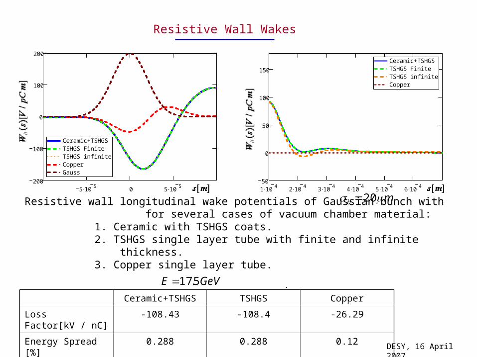
Resistive Wall Wakes
Resistive wall longitudinal wake potentials of Gaussian bunch with for several cases of vacuum chamber material: 1. Ceramic with TSHGS coats. 2. TSHGS single layer tube with finite and infinite thickness. 3. Copper single layer tube.
mb 20
Ceramic+TSHGS TSHGS Copper
Loss Factor[kV / nC]
-108.43 -108.4 -26.29
Energy Spread [%] 0.288 0.288 0.12
GeVE 5.17
DESY, 16 April 2007

.
Geometrical Wakes
Geometrical longitudinal wake potentials of Gaussian bunch mb 20
Entrance Exit Total
Loss Factor[kV / nC]
0.36 -462.39 -462.1
Energy Spread [%] 1.12*10^(-3) 1.057 1.058
GeVE 5.17
DESY, 16 April 2007
mma 102 mma 251
mL 9.0
5 105
0 5 105
600
400
200
0
200
TotalGaussEntranceExit

.
Surface Roughness in Undulator Section
DESY, 16 April 2007
mm
R.m.s. distortion m568.0
0 200 400 600 8006
4
2
0
2
4CorugatedIdeal
0 200 400 6001
0.5
0
0.5
1CorugatedIdeal
Measurement data from T. Wohlenberg

.
DESY, 16 April 2007
1
0
( ) ( )( ) 1
2 2s sZ ZR
Z iR c Z
( ) ( ) ( )Ls s sZ Z Z
( )( )s
iZ
( )LsZ i L
G.V.Stupakov, SLAC-PUB-8208, 1999M.Dohlus, M.I. Ivanyan, V.M. Tsakanov, TESLA-FEL 2000-26,2000M.Dohlus. TESLA 2001-26, 2001
mmR 4.4
mΩ1085σ -1-16
where
Surface Impedance
Inductance define as
22
20 ),(
~
2zx
zzxzx
kk
kkkRdkdk
ac
ZL
Where is spectral density defined as Fourier Transformation
of Autocorrelation function: ),(
~zx kkR
),(
ˆˆ)]ˆ,ˆ()ˆ,ˆ([),(
1),(
zxA
zdxdzzxxrzxrzxA
zxR
2m
.
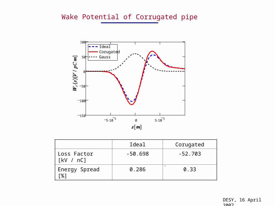
Ideal Corugated
Loss Factor [kV / nC] -50.698 -52.703
Energy Spread [%] 0.286 0.33
DESY, 16 April 2007
Wake Potential of Corrugated pipe
5 105
0 5 105
150
100
50
0
50
100IdealCorugatedGauss

DESY, 16 April 2007
AL_AU AL_CU AL_ELP AL_UNB AL_GEB
Meas. 1 0.568 0.371 0.395 0.567 2.835
Meas. 2 0.547 0.745 0.360 0.520 ------------
Meas. 3 0.514 0.418 0.346 0.457 ------------
R.m.s. value of the roughness in m
AU Gold
CU Copper
ELP Electro polish
UNB Untreated (Unbehandelt)
GEB Etched (Gebeizt)
Abbreviations
AL_AU AL_CU AL_ELP AL_UNB AL_GEB
Meas. 1 0.425 0.288 0.312 0.463 2.202
Meas. 2 0.430 0.362 0.285 0.418 ------------
Meas. 3 0.410 0.333 0.274 0.356 ------------
Arithmetical Mean Roughness ][Ra m

Acknowledgements:
Thanks to Martin Dohlus, I. Zagorodnov,T. Wohlenberg, M. Ivanyan and
V. Tsakanov for stimulating discussions.
Summary
• Impedance Structure for Ceramic Kicker Vacuum Chamber was
Investigated. For Kicker was shown that Wake Potential for two
layer tube can be estimated by single layer tube formula.
• Was analyzed the transition Wakes influence on the beam.
• Influence of surface corrugation in Undulator vacuum chamber on the beam was
calculated.


