Resolution limits of holographic mapping filters forgeometric coordinate transformations
Finn Mengel
A recently proposed position, rotation, and scale-invariant optical pattern recognition system using aholographic logpolar mapping filter is analyzed with respect to resolution and accuracy. The limits are set bythe resolution of the mapping filter, which must have a bandwidth proportional to the square of the inputbandwidth. With 1800 X 1800 pixels in the computer-generated mapping filter, we get a maximum inputfield of 24 X 24 pixels and an angular resolution of 4.80. Determination of the position of the input object ispossible with at best 50% relative accuracy, and, in practice, multiobject capability is highly questionable.Numerical simulations and experimental evidence support the resolution limits found.
1. Introduction
Map transformations in optical processing using ho-lographic filters have been employed (1) to achievecoordinate transformations for scale- and/or rotation-invariant pattern recognition1-6; (2) to redistribute im-age energy to match a certain detector geometry forfeature extraction7' 8; or (3) to provide optical intercon-nects, e.g., for 2-D fiber arrays. The holographic map-ping filters used in these applications can be consid-ered as gratings with a spatially varying gratingconstant and orientation designed to steer light fromany one input element onto the desired ouptut ele-ments. In (1), the grating varies continuously, while(2) and (3) generally require discontinuous multifacetgratings. Both types of grating filter can convenientlybe implemented as a computer-generated holograms.
We consider here the continuous case and in particu-lar the logpolar filter for rotation- and scale-invariantoptical image processing,3'4'6 although the resolutioncriteria are also valid for discrete multifacet filters.The mapping action of continuous filters is describedby a diffraction integral, which, when solved by a sad-dle point integration, gives the desired mapping.9 Ouraim is to quantify the restrictions imposed by thestationary phase assumption and derive resolution
The author is with Dantec Elektronik A/S, Tonsbakken 16, DK-2740 Skovlunde, Denmark.
limits for the mapping process given the resolution ofthe various components. Although the logpolar filterhas previously been demonstrated experimentally,3 4 6
detailed resolution considerations have not been pub-lished. We also show that the resolution conditionscan be deduced directly from simple diffraction spotsize considerations.
11. Log-Polar Mapping Correlator
In Ref. 10, Skov Jensen et al. suggested the opticalsystem in Fig. 1 for a position, scale, and rotation-invariant pattern recognition system. It consists of amapping section, plane 1-3, and a standard correlator,plane 3-5, correlating the amplitude of the mappedspectrum of the input object with a matching filterplaced in plane 4. The input spatial light modulator(SLM1) is used for incoherent-to-coherent conversion,while SLM2 is needed to convert the divergent beam inplane 3 to a parallel beam for the correlator. All lensesare assumed to have equal focal lengths without loss ofgenerality.
The idea behind the system is to transform the inputpattern from a rectangular to a logpolar representa-tion, converting rotation and scale changes to shifts,which can be determined by the correlator. In con-trast to the system considered in Ref. 4, the mappingfilter is set to act on the Fourier spectrum of the input,as originally suggested in Ref. 11, rather than on theinput itself. Since the Fourier spectrum is alwayscentered on the optic axis, simultaneous position androtation/scale invariance is achieved at the cost, how-ever, of loosing the phase information in the Fourierspectrum. Since the Fourier amplitude is point sym-metric, the mapped spectrum repeats itself in the 0direction, giving in general four peaks in the correla-tion plane with a spacing corresponding to 180°. As
Fig. 1. Basic layout of the optical system. Beam splitters forreading the spatial light modulators are not shown. Plane 1-3 is themapping section operating at 442 nm, plane 3-5 the correlator sec-
tion operating at 633 nm.
one important consequence of this, we get an ambigu-ity of 1800 in the rotational angle determination.Since the phase part of the spectrum is usually moreimportant than the amplitude, we also expect a lowerdiscrimination capability than that of a standard cor-relator. While in Ref. 11, only the Fourier intensity ismapped, Ref. 10 suggests the mapping of the full com-plex spectrum, thus maintaining the linear phase termcontaining the position information. One should thusbe able to handle multiobject inputs and determine theposition of each object, since a shift of the input causesan identical shift of the output. The location of thecorrelation peaks will be a linear combination of thescale factor/rotation angle and the x/y-coordinates ofthe input. Two independent measurements must bemade to determine all four parameters, e.g., by rotat-ing the input by 900 between measurements. Theprice of this capability, as shown below, is an increaseddistortion compared to the configuration, where thephase is removed before the mapping filter,7 althoughthe difference is not really significant. In both cases,the requirement for low distortion is very restrictive.
Ill. Analysis
Denoting the coordinates in planes 1, 2, and 3 of Fig.1 by the vectors r, r2, and r3, respectively, we maywrite the field distribution in plane 3 as9 36 10
where k and f are the wave number and focal length,respectively, (r2) is the phase function of the map-ping filter, and H(r2) is the Fourier spectrum of theinput pattern h(rl):
H(r2) = 2 f h(rl) exp(-ik/f r r 2)d2r,. (2)
2Fzrif
For the logpolar mapping filter, 4(r 2 ) is given by 3
,P(r2 ) = kd/27rf (x2 ln(r2/ro) - Y2 02 - X2)
performed the mapping:
X3 = d/2ir- ln(r2 /ro),
(3)
(4)Y3 = -d/21r * 02,
where r2, 02 are the polar coordinates in plane 2, and d isthe height of the mapped output pattern. d is onerepresentation of what we call the filter constant.From Eqs. (4) we see that the size of the mappedpattern is [d/2,r ln(r 2 max/r 2 min),d] in the x and y direc-tions, respectively, where r2min and r 2max are the mini-
mum and maximum radii of the annular shaped map-ping filter. The scaling factor ro gives a carrier in the xdirection. It is convenient to express the filter func-tion in normalized coordinates
4(r') = a * [x'. ln(r'/r) - y'o - x'] (5)
with the spatial coordinates normalized by the filterradius r2max, e.g., x' = x2/r2max. The normalized filterconstant is given by
d * k * r2max2 7r-f (6)
In the stationary phase approximation, the phasefunction 4(r2 ) is expanded to second order around thestationary phase point r2, and the integral (1) is solvedby setting H(r2) outside the integral sign. This ap-proximation is valid if H(r2 ) is slowly varying com-pared to the exponential in Eq. (1). In the input plane,this corresponds to an upper limit on the size of theinput function h(rl).
This restriction can be quantified by rewriting theintegral (1) by inserting Eq. (2) and maintaining thesecond-order expansion of b(r2 ). It is shown in Ref. 10that, apart from a phase factor, the output field T(r3) isidentical to that of an ideal logpolar transform of adistorted input h'(rl):
Thus, if the distorting phase factor inside the exponentin Eq. (7) is small, h'(r1 ) h(rl), and we have lowdistortion. Somewhat arbitrarily, but definitely opti-mistically, one can define the low-distortion limit byrequiring the phase factor to be smaller than 7r/2:
(8)
Requiring this condition to be fulfilled for all inputpoints and rotation states for the logpolar filter (3) onegets the condition that the input object should liewithin a circle of diameter D:
D = 2 f \/(a7r). (9)k r2max
Although this relation was also derived in Ref. 10, itsimpact on the resolution of the system was not recog-nized correctly.
If the input SLM has a pixel density of N pixels/m,the Fourier spectrum is confined in plane 2 within acircle of radius:
_f - 7r -Nr2max k
Inserting Eq. (10) in Eq. (9), we get
D = N- 2V(a/r)
or in pixels
n = 2/(a/7r).
(10)
(11)
(12)
The ratio between the mapped output pattern heightand the maximum input image size is given by
Our computer-generated mapping filter master is tobe plotted directly on an analog raster plotter with aspace-bandwidth product of M X M. If we design thefilter to map the area rmin = exp(-ir) < r' < 1 (onto arectangle of size d/2 X d) and choose the smallest valueof the carrier frequency, which separates the first- andsecond-order diffraction patterns [r' = exp(7r)], it canbe seen from Eq. (5) that the Nyquist sampling rate isreached for r' = exp(-7r) when
amax = M/4, (14)
giving the relation between the total number of pixelsin the processing filter and the processed image:
M2 = 72 . n4. (15)
Having arrived at this relation the hard way, it isinstructive to realize that not only is it a pretty obviousrelation, but it could have been arrived at using almostno mathematics at all through simple diffraction spotsize considerations. For this purpose, consider in Fig.2 a 1-D close-up of plane 2 of Fig. 1. The input field,consisting of n independent plane wave elements ofsize Ax, must be directed onto m distinguishable outputangles by the n grating facets in the filter. For anonlinear mapping, m will in general be greater than n.The output angle 02 for a given input element is givenby the grating equation
02 k7 + 01, (16)
where 1 is the local grating spacing and 01 the inputangle of incidence. Due to diffraction, the angularspread of each element will be
= = (17)kbx
The difference between the maximum angular devi-ation 0max, given by the minimum grating spacing 1
min,
and the minimum angle Omin must be large enough toaccommodate all output elements:
Omax - min = M60- (18)
In a holographic encoding, a carrier must be added tothe filter to separate first and second diffraction or-ders, giving the requirement
Omax = 20 min- (19)
Combining the above relations assuming a real-valuedinput, where 01 = 0, we get the minimum line spacingrequired in the filter,
a~xmin= 4m' (20)
and the number of pixels needed in the mapping filter:
M = 2 nbx = 8nm. (21)'min
This relation is valid for a real valued input field, but inour case, where the input is the Fourier transform of areal input function, 01 is in general nonzero and causesan increase of the angular spread 60. It can easily be
i nput filter a
ein
Gmax
Size: nax M. min2
Fig. 2. One dimensional close-up of the filter plane 2. The inputconsists of n pixels of size Ax, the filter of n grating facets with aminimum line spacing of 1min limited by the number of pixels M inthe filter. The densest grating element deflects at an angle Omax-
shown that the worst case angular spread will be 1.5times larger than that of Eq. (17), independently of thefocal length of the first Fourier lens. For the logpolarfilter we have m = rn, and, as discussed above, bycutting away the uninteresting half of the output pat-tern, we can use a carrier frequency half that given byEq. (19), giving our final result:
M = 67rn2 . (22)
The worst-case relation (22) thus differs from thesquare root of the optimistic relation Eq. 12 by a factorof 6. The practical resolution limit probably liessomewhere between.
The impact of this requirement on the resolution ofthe actual system is rather unfavorable. With a de-cent hologram plotter resolution of 1800 X 1800 pixels,we get from Eq. (15) a maximum input field of only 24X 24 pixels with a finest angular information of 4.80.According to Eq. (13), input objects must be separatedby 38 times the maximum object diameter to com-pletely avoid overlap in plane 3. These figures empha-size the heavy requirements on the system bandwidthneeded by an optical mapping processor, as realized inRef. 13.
The positional accuracy is connected to the accuracywith which the correlation peak can be located. Dueto the nonlinear nature of the mapping (4), the space-bandwidth product in plane 3 will be expanded by afactor of r in each direction. Thus, with the abovechoice of rin, a total of 7rn/2 X rn pixels in plane 3must be allocated to hold the logpolar representationof the n X n pixel input field. If we assume that theSLM2 has sufficient resolution to fulfill this and thatthe correlator is able to determine the peak of thecorrelation pattern with one-pixel accuracy, we get thepositional accuracy br1 from Eqs. (12) and (13):
br1 = r3 - d/n7r = D/2. (23)
Thus a shift of the correlation pattern in the outputplane of one resolution element corresponds to a shiftof the input pattern of one-half of the maximum objectdiameter, independent of the filter constant; i.e., therelative positioning accuracy will be no better than50%. Clearly, this accuracy is not very useful, andwhile the angular resolution can be improved by a finermapping filter, the relative positional accuracy cannot.
Since multiobject and positioning capability cannotbe achieved anyway, we might as well try to reducedistortions by removing the phase information beforethe mapping filter. 7 This can be done by movingSLM2 to plane 2 before the filter. Since the mappedpattern is then always centered on the optic axis, theundesired phase function in plane 3 can be equalizedby another computer-generated filter whose planefunction is the conjugate of (3). As shown above, thisonly lessens the requirements on the mapping filterbandwidth by a marginal factor of 1.5.
We have only considered the fundamental limita-tions to the system, assuming all components to beideal. If it was possible to create a mapping filter withvery high bandwidth, using a high-resolution comput-er plotter or analog multifacet recording, some majorpractical problems must be solved. Most important,the bandwidth of the optics ensuing the mapping filtermust be equal to or greater than that of the filter.Using a high-resolution high-efficiency recording ma-terial like a thick DCG hologram, the filter must becoded on a high-frequency spatial carrier because ofthe angular bandwidth limitation of thick holograms,giving a large diffraction angle of the outgoing beam.Since a large filter constant gives a large output imagesize according to (4), the optics must reduce the size ofthis off-axis image to fit it into the output SLM. De-signing an optical system to do this may not be simple.
IV. Numerical Simulation
The spatial carrier is not needed in a computer simu-lation, and the filter constant can be doubled relativeto Eq. (14). With M = 200, set by the memory size inthe PC-AT type computer used, we get amax = 100 andn = 11 pixels. When a = amax, the mapping filter issampled at the Nyquist rate, and, since we must multi-ply by the input spectrum, the Nyquist rate will ingeneral be exceeded, resulting in aliasing in the calcu-lated patterns. Rather than reduce the resolution, weprefer to accept this. Similarly, due to the cyclic na-ture of a FFT, we should ideally double the number ofpixels to represent accurately the correlation function.By not doing so, we get correlation patterns where theupper and lower parts are folded into the central part.Instead of the four peaks in the autocorrelation func-tion mentioned above, we get two identical peaks. Inspite of these limitations, we will be able to get aquantitative feeling for the sort of mapping distortionsand correlations to expect.
As test patterns, we have used binary rectangles,whose spectra are 2-D sinc functions. Note that in allcalculated patterns, we show the field amplitude rath-er than the intensity. In Fig. 3, we compare the ideallogpolar mapped spectrum of a 11 X 7-pixel rectangleto the simulated pattern. Even though the input sizeobeys condition (12), some distortions are visible, re-flecting the arbitrariness of the limit (8). In Fig. 4(A),the linear size of the rectangle is doubled to 23 X 15pixels, resulting in distortions splitting the +90 and-90° part of the spectrum into two branches corre-sponding to each of the two plane waves, which locally
A BFig. 3. Calculated field amplitude in plane 3 of an 11 X 7-pixelrectangle in a 200 X 200 field. The horizontal axis corresponds to-r < log(r) < 1, the vertical axis to -7r < 0 < 7r: (A) ideal logpolar
mapping; (B) simulated optical mapping.
A B CFig. 4. Calculated mapping of a 23 X 15-pixel rectangle: (A) am-plitude in plane 3; (B) amplitude; and (C) phase of the mapping ofFourier amplitude alone. (SLM2 is moved to plane 2, and a conju-gate phase-equalizing filter is placed in plane 3.) In (C), black
corresponds to -r and white to 7r.
approximately constitute the spectrum. The distancebetween the branches is, of course, equal to the size ofthe input rectangle, since the distortions are essential-ly a high-pass filtered version of the input image over-laying the desired mapped spectrum. An intuitivecondition for low-distortion mapping can be formulat-ed by requiring the directly imaged pattern to be muchsmaller than the mapped pattern. This is exactly thesort of condition given by Eq. (13).
In Figs. 4(B) and (C), we have simulated the alterna-tive configuration with SLM2 placed before the map-ping filter and the phase equalizing filter in plane 3. Itis clear that the distortion are reduced considerably,although the phase equalization 'is not complete.
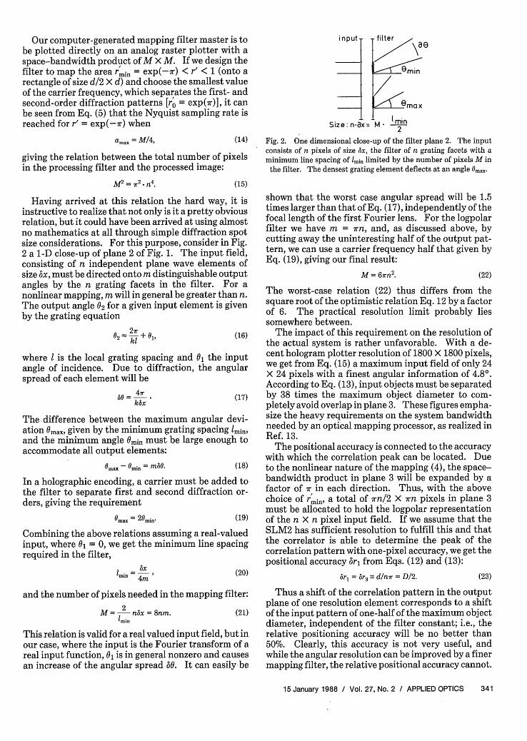
In the final example in Fig. 5, we show the mappedspectrum of a two-object scene, consisting of a rectan-gle and triangle, separated by approximately twicetheir size. The interference between the two overlap-ping patterns makes the individual components hardto separate visually. A simulated correlation experi-ment using a matched filter of the triangle did not giveindentifiable peaks.
Admittedly, the sharp-edged test patterns are par-ticularly nasty, because the Fourier spectrum locallyconsists mainly of two plane waves approaching theworst-case case angular spread 0 discussed above.
A B CFig. 5. Calculated mapping of a two-object scene with a reactangleand a triangle: (A) rectangle alone; (B) triangle alone; and (C) both
objects present.
Most real-world spectra have smoother phase varia-tions. Due to the low bandwidth available in the simu-lation, more realistic test patterns are not possible.For the same reason, rotated versions of an objectdiffer from each other due to discretization effects.Thus only calculated correlations between unrotatedobjects can be trusted.
A number of correlation patterns using various typesof matching filter have been calculated. A generalfeature of all the correlations with classical matchedfilters is the presence of very broad correlation peaks,which will be very hard, if not impossible, to locatewith one-pixel accuracy. This is a consequence of therequirement for low-distortion mapping. Only verysmooth patterns (in plane 2) can be mapped correctly;thus the patterns in plane 3 will also be rather smoothand, since the phase is removed, so will the correlationpatterns. The correlation peaks can be sharpened byusing high-pass matching filters, e.g., a phase-only fil-ter.1 4 Similarly, distortions may be countered by cre-ating synthetic discriminant filters with a number ofdistorted mapped patterns as the training set.15 Anumber of simulations have shown a marked improve-ment in the correlation peak shape, but these improve-ments come at the cost, however, of an increased sus-ceptibility to noise.
V. Experiments
The optical system in Fig. 1 has been implementedusing a mapping filter developed at the Riso NationalLaboratory.10 The hologram was made by plotting thecosine of the phase function (5) on photosensitive pa-per on an analog drum recorder with 1800 X 1800addressable points. The A4 size master was the pho-toreduced to a 35-mm film and subsequently copiedonto dicromated gelatine at 488 nm in the convention-al way.1 2 16 The filter constant was a = 200. A spuri-ous linear grating was superimposed on the final filterdue to insufficient spatial filtering of the zero-orderdiffraction in the copying process. Consequently, aninverted image of the input mask was present in plane3. The input SLM1 was replaced by a transparency,illuminated by a collimated beam at 442 nm. SLM2was a transmission-type liquid crystal light valve man-
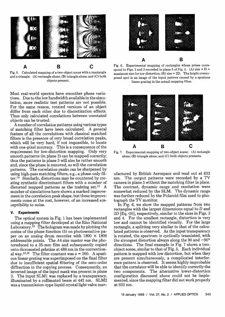
Fig. 6. Experimental mapping of rectangles whose prizes corre-spond to Figs. 2 and 3 recorded in plane 5 of Fig. 1: (A) size = D =maximum size for low distortion; (B) size = 2D. The bright overex-posed spot is an image of the input pattern caused by a spurious
linear grating in the actual mapping filter.
A B CFig. 7. Experimental mapping of two-object scene: (A) rectangle
alone; (B) triangle alone; and (C) both objects presents.
ufactured by British Aerospace and read out at 633nm. The output patterns were recorded by a TVcamera in plane 5 without the matching filter in place.The contrast, dynamic range and resolution weresomewhat reduced by the SLM. The dynamic rangewas further reduced by the Polaroid film used to pho-tograph the TV monitor.
In Fig. 6, we show the mapped patterns from tworectangles with the largest dimensions equal to D and2D [Eq. (9)], respectively, similar to the sizes in Figs. 3and 4. For the smallest rectangle, distortion is verylow and cannot be identified visually. For the largerectangle, a splitting very similar to that of the calcu-lated patterns is observed. As the input transparencyis rotated, the spectrum is cyclically translated, withthe strongest distortion always along the 90 and -90°directions. The final example in Fig. 7 shows a two-object scene, similar to that of Fig. 5. Each individualpattern is mapped with low distortion, but when theyare present simultaneously, a complicated interfer-ence pattern is observed. It seems highly improbablethat the correlator will be able to identify correctly thetwo components. The alternative lower-distortionconfiguration discussed above could not be imple-mented, since the mapping filter did not work properlyat 633 nm.
We have analyzed a configuration for a position-,rotation-, and scale-invariant optical pattern recogni-tion system using a holographic mapping filter. Thesystem resolution depends only on the resolution of theholographic mapping filter, whose bandwidth must beabout equal to the product of the input and outputbandwidths. Contrary to our initial expectations,multiobject and positioning capability is very ques-tionable. There are no design trade-offs and the reso-lution of the input light modulator only affects thefield of view of the system. Combined with anothersystem to isolate and zoom in on a single object, howev-er, a variant of the present system could be useful tomeasure the rotation state of a single object with anambiguity of 1800. Although the mapping filter puts aheavy load on the system bandwidth, it should enableus to achieve slightly higher resolution than that avail-able with commercially available wedge-ring detec-tors.
H. P. Christensen from Dantec is acknowledged forsetting up the experiment and helpful discussions, L.Lindvold, E. Rasmussen, and A. Jensen from Riso forsupplying the mapping filter, and D. Hart and D. Tun-nicliffe from British Aerospace Sowerby ResearchCentre for supplying the SLM. This work was sup-ported by the European Commission through the ES-PRIT programme.
References
1. D. Casasent and C. Szczutkowski, "Optical Mellin Transforma-tion using Computer-Generated Hologram," Opt. Commun. 19,217 (1976).
2. T. Yatagai, K. Choji, and H. Saito, "Pattern Classification usingOptical Mellin Transform and Circular Photodiode Array," Opt.Commun. 38, 162 (1981).
3. J. Cederquist and A. Tai, "Computer-Generated Holograms forGeometric Transformations," Appl. Opt. 23, 3099 (1984).
4. Y. Saito, S. Komatsu, and H. Ohzu, "Scale and Rotation Invari-ant Real Time Optical Correlator using Computer GeneratedHologram," Opt. Commun. 47, 8 (1983).
5. H. Bartlet and S. K. Case, "Coordinate Transformations viaMultifacet holographic Optical Elements," Opt. Eng. 22, 497(1983).
6. W. J. Hossack and M. A. Fiddy, "Log/Polar Transformation byComplex CGH for Real Time Optical Pattern Recognition," IEEColloq Opt. Tech. 6, 12.1, (1985).
7. D. Casasent, S. -H. Xia, J. -Z. Song, and A. Lee, "DiffractionPattern Sampling using a Computer-Generated Hologram,"Appl. Opt. 25, 983 (1986).
8. D. Casasent and A. Lee, "Optical Relational-Graph Rule-BasedProcessor for Structural-Attribute Knowledge Bases," Appl.Opt. 25, 3065 (1986).
9. 0. Bryngdahl, "Geometrical Transformations in Optics," J. Opt.Soc. Am. 64, 1092 (1974).
10. A. Skov Jensen, L. Lindvold, and E. Rasmussen, "Transforma-tion of Image Positions, Rotations, and Sizes into Shift Parame-ters," Appl. Opt. 26, 1775 (1987).
11. D. Casasent and D. Psaltis, "New Optical Transforms for Pat-tern Recognition, " Proc IEEE 65, 77 (1977).
12. S. Lowenthal and P. Chavel, "Reduction of the Number ofSamples in Computer Holograms for Image Processing," Appl.Opt. 13, 718 (1974).
13. D. Casasent and D. Psaltis, "Deformation Invariant, Space Vari-ant Optical Pattern Recognition," Prog. Opt. 16, 289 (1978).
14. J. L. Horner and P. D. Gianino, "Phase-Only Matched Filter-ing," Appl. Opt. 23, 812 (1984).
15. D. Casasent, "Unified Synthetic Discriminant Function Com-putational Formulation," Appl. Opt. 23, 1620 (1984).
16. H. Bartelt and S. K. Case, "High-Efficiency Hybrid Computer-Generated Holograms," Appl. Opt. 21, 2886 (1982).
Kenneth F. Walsh of GCA/Tropel, a participant in the Rochester,NY 1987 AMOSA. Photo: F. S. Harris, Jr.