Resource Allocation for Device-to-Device Communication Underlaying Cellular Network A thesis submitted in partial fulfillment of the requirements for the degree of Master of Technology in Communication Engineering by Indranil Mondal (143070001) Under the guidance of Prof. Abhay Karandikar and Prof. Prasanna Chaporkar Department of Electrical Engineering INDIAN INSTITUTE OF TECHNOLOGY BOMBAY June, 2016
Transcript
Resource Allocation for Device-to-Device
Communication Underlaying Cellular Network
A thesis submitted in partial fulfillment of
the requirements for the degree of
Master of Technology
in Communication Engineering
by
Indranil Mondal (143070001)
Under the guidance ofProf. Abhay Karandikar
and
Prof. Prasanna Chaporkar
Department of Electrical Engineering
INDIAN INSTITUTE OF TECHNOLOGY BOMBAY
June, 2016
Dedicated to my parents
i
ii
Abstract
Device-to-Device (D2D) communication is expected to play a major role for en-
hancing system capacity in the fifth generation wireless networks. The gains are
expected due to the possibility of reusing resources allocated to the cellular users
(CUs) for the D2D underlay network. This allows for the resource reuse in the
same cell and thus may lead to a significant interference. The key challenge is
to devise resource allocation schemes for the D2D communication that does not
adversely affect CU’s communication. Resource allocation can be done to achieve
various performance objectives like maximizing network throughput, minimizing
delay, achieving fairness among user data rates, etc. In this work, our aim is to
propose a polynomial time proportional fair (PF) resource allocation scheme that
respects the rate requirements of the CUs. The proposed scheme can potentially
work with any resource allocation scheme for CUs and can adapt to the time and
location varying channel conditions. Our scheme allows for allotting more than one
resource block to a D2D pair. The performance of the proposed scheme is validated
With the ushering in of new applications, the requirement of high data rates have
increased tremendously over the past few years. However, due to the spectrum
shortage, supporting such growing data rate requirements has been a technical chal-
lenge. The fifth generation of wireless networks promises to address this problem.
In this context, D2D communication is expected to play a major role to improve
network throughput and spectral efficiency by offloading traffic at the base sta-
tion (BS) and enhance the performance and quality of service (QoS) of local area
services, context-based applications, etc. [1]. However, to increase the spectral effi-
ciency of the network for D2D communication, reusing the resources of the CUs in
an efficient manner is critical as this may cause severe interference to the CUs. One
of the main constraints in resource reuse is that the D2D communication should
not disrupt CUs communication. Once this requirement is met then one needs to
address how resource allocation for D2D communication should be done. Resource
allocation can be done to achieve various performance objectives. In this work, we
focus on PF resource allocation as it strikes a good trade-off between throughput
and fairness among users [2].
In this chapter, we present basic concepts of D2D communication in the licensed
spectrum, existing scheduling techniques for cellular networks, some open research
problems for D2D resource allocation and our contributions towards solving some
of those problems.
1.1 Basics of D2D Communication
D2D communication is envisioned to be a key technology component for the next
generation wireless network (5G) to offload network traffic and enable new proximity-
based services [1]. D2D communication commonly refers to the communication
between two or more devices directly, i.e. single hop communication without any
need of infrastructure or BS, while for the existing cellular network user-to-user
communication is two hop communication via the BS as an intermediate node.
D2D communication may be categorized [3] in three types:
• Peer-to-peer communication: This is like conventional point-to-point (P2P)
communication.
• Cooperative communication: In this type of communication, devices act as
relays to extend cell coverage.
• Multiple-hop communication: This is like an extension of cooperative commu-
nication where multiple devices form an ad-hoc mesh network to enable data
routing between devices.
1.1.1 Configurations of D2D Communication
There are different configurations [3] of the D2D networks discussed below:
• Network-controlled D2D: The base station and the core network controls the
signalling setup and thereafter resource allocation for both CUs and D2D
pairs. The centralized control can result in efficient interference management
and resource allocation.
• Self-organized D2D: This configuration is distributed in nature. D2D users
sense the spectrum holes, collect channel state information (CSI) and possi-
ble interferences much like cognitive-radio (CR) and communicate in a self-
organizing way to other D2D pairs. Thus, it reduces signalling overhead but
may create instability due to lack of centralized control.
• Network-assisted D2D: In this scenario, the BS only allocates resources to
the D2D users and thereafter users communicate between themselves in a
self-organizing way. This method has low signalling overhead and also par-
tial centralized control to avoid communication chaos, but security can be a
potential issue.
2
1.1.2 Device Synchronization and Discovery
Synchronization between CUs and D2D pairs is important for resource allocation
and interference management. Proper hand-off of D2D pairs is also possible through
the synchronization process. For D2D discovery, one device should keep on trans-
mitting a reference signal (a beacon) and can thus detect devices in its proximity.
Accordingly, it can choose the pairing device with the best channel condition. This
discovery procedure can be network-assisted or non network-assisted. In network-
assisted discovery process, the BS mediates the discovery procedure, thus making it
more energy efficient and less time consuming. In non network-assisted discovery,
devices keep on searching for its pairing devices blindly, thus can be more power
hungry.
1.1.3 Mode Selection
Mode selection is one of the important issues in D2D communication. In conven-
tional cellular mode, data is transmitted via the BS, while in D2D mode data is
transmitted directly between users. The BS decides modes according to different
scenarios. Modes are generally classified [3] into three categories:
• Cellular: All devices in the network communicate in cellular mode.
• Forced D2D: All devices are forced to communicate in D2D mode in this
scenario.
• Path-loss D2D: D2D mode is chosen according to relative channel gains be-
tween the communicating devices, one via the BS and another direct channel
gain. If the direct channel gain is better, D2D mode can be selected.
1.1.4 Resource Management
Resource allocation for D2D communication can be mainly classified into two cat-
egories [3]:
• Overlay D2D Communication: In this scenario, allocated channels to the CUs
and D2D pairs are orthogonal, thus eliminating any possibility of interference.
However, in terms of spectral efficiency no gain is achieved.
• Underlay D2D communication: In this scenario, D2D pairs share same chan-
nels as the CUs, thus causing potential interference to CUs. However, with
3
efficient interference avoidance techniques, gain in spectral efficiency can be
achieved.
1.1.5 Application Areas
D2D communication can be a key component to offload network traffic and increase
spectral efficiency. It can also explore local area and proximity-based services like
file sharing, online gaming, video streaming, etc. [3]. In the latest 3GPP releases,
D2D communication has also been envisioned to be a key technology component
for public safety in the absence of network infrastructure due to some disaster. It
can also find applications in Machine-to-Machine communication and Internet of
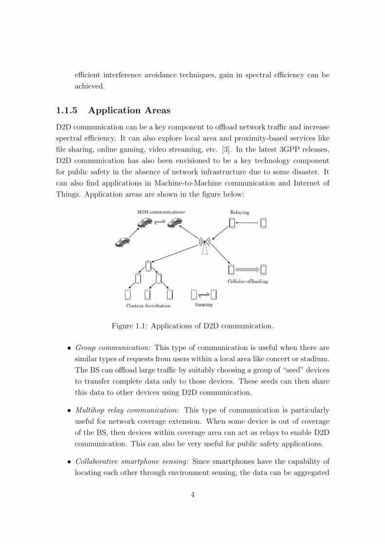
Things. Application areas are shown in the figure below:
Figure 1.1: Applications of D2D communication.
• Group communication: This type of communication is useful when there are
similar types of requests from users within a local area like concert or stadium.
The BS can offload large traffic by suitably choosing a group of “seed” devices
to transfer complete data only to those devices. These seeds can then share
this data to other devices using D2D communication.
• Multihop relay communication: This type of communication is particularly
useful for network coverage extension. When some device is out of coverage
of the BS, then devices within coverage area can act as relays to enable D2D
communication. This can also be very useful for public safety applications.
• Collaborative smartphone sensing: Since smartphones have the capability of
locating each other through environment sensing, the data can be aggregated
4
collaboratively to a “sink” node much like wireless sensor networks. There-
after, the collected data can be sent to the BS.
1.2 Scheduling Techniques in Cellular Network
In wireless communication systems, the need to simultaneously and reliably provide
multiple users with high-rate communication links leads to challenging optimization
problem. Questions of resource block assignment, interference, and power consump-
tion at the BS and mobile devices have to be answered in the face of time varying
and frequency selective channels. Furthermore, delay and data rate requirements
may greatly vary among devices and applications. This questions and requirements
can be formulated as resource allocation problems.
The medium access control (MAC) scheduler is an important entity of the BS
and is responsible for allocating radio resources to the users. It takes into account
CSI, rate requirements and fairness among users before any scheduling decision is
made. Since long term evolution (LTE) is an all IP network, maintaining QoS for
all user requirements is a crucial task. Hence, the LTE MAC scheduler needs to
take into account QoS requirements of the CUs. Radio resources are scarce entities,
thus must be allocated efficiently to the users. We need to evaluate the efficiency
and functionality of existing scheduling algorithms before evaluating scheduling of
D2D users. A survey on existing scheduling techniques in LTE has been presented
in [4].
Three basic scheduling algorithms namely, round robin (RR), maximum rate
(MR) and proportional fair (PF) scheduling can be used in LTE networks. They
can be compared in terms of network throughput and fairness among users.
The simplest one is the RR scheduling algorithm. It gives same priority to all
the users in a scheduling interval. It doesn’t take into account CSI at all, hence,
suffers from low network throughout as some users with deep fade may also be
scheduled. Though it provides the best fairness among users, it fails to satisfy
QoS requirements in general. It performs well if all the users have similar average
signal-to-interference-plus-noise ratio (SINR) all the time which is not the case in
a practical scenario.
For the MR scheduler, it takes into account CSI of all the users before scheduling
decisions are made. In each scheduling interval, it allocates resources to those users
which have good channel conditions, thus achieving higher throughput and spectral
efficiency. However, it doesn’t take into account fairness among users at all. A cell
5
edge user with poor channel condition may starve for long.
A PF scheduler strikes a good balance between throughput and fairness among
users. It allocates resources to the users according to their long term average channel
conditions relative to others. Hence, it takes into account both CSI in the present
slot and the long term service rate till the previous slot.
The intuition behind the mathematical formulation of the scheduling algorithms
are explained below: Assuming that the scheduler has knowledge of the instan-
taneous CSI of CU c in sub-frame n on resource block k, it can determine the
achievable data rate Rc,k[n] that the CU c can achieve on resource block k. It also
maintains the moving average throughput Tc,k[n] of each CU c on every resource
block k, over a past window of length tw. The parameter tw maintains the latency
of the system. A small value of tw approaches towards RR algorithm, while a large
value approaches towards MR algorithm. Therefore, the value of tw should to be
chosen according to the scheduling policy. The scheduler allocates resource block k
to user c∗ in sub-frame n if it maximizes the relative channel quality function given
by,
c∗ = arg maxc=1,2,...,C
[Rc,k[n]]γ
[Tc,k[n]]δ(1.1)
• if γ=1, δ=1, the Equation 1.1 describes the PF algorithm.
• If γ=1, δ=0, it describes the MR algorithm.
• If γ=0, δ=1, it describes the RR algorithm.
The scheduler updates the long term average rate Tc,k[n] of the UE c in time slot
n on the resource block k using an exponential moving average filter [4] of length
tw given below,
Tc,k[n+ 1] =
{(1− 1
tw)Tc,k[n] + 1
twRc,k[n], , c∗ = c
(1− 1tw
)Tc,k[n] , c∗ 6= c
Equation 1.1 is repeated on each resource block k independently to allocate all
the resource blocks to the users in each sub-frame n.
1.3 Some Research Issues
In this section we discuss some open research issues in resource allocation of D2D
communication. We also discuss our contributions to the research problems which
6
have been discussed in the subsequent chapters.
We have already discussed two resource management techniques in Section 1.1.4
for D2D communication. In overlay mode, orthogonal sharing of resources between
cellular and D2D user causes no interference to each other, but no gain in spectral
efficiency is achieved. In underlay mode, D2D users share same resources with
the CUs while staying under the control of the BS. Thereby the utilization of the
spectrum can be increased by limiting harmful interference to the CUs.
There has been considerable amount of research on spectrum-sharing between
cellular networks and infrastructure-less networks [5], [6], [7]. Due to heavier down-
load traffic, uplink spectrum is under-utilized in frequency division duplex (FDD)
based cellular system with equal bandwidths allocated for the uplink and downlink
transmissions. In [5], the transmission-capacity trade-off between the coexisting cel-
lular and mobile ad hoc networks is analyzed for different spectrum sharing methods.
The authors suggest that mobile ad-hoc network can co-exist with cellular network
while achieving higher transmission capabilities. They have derived bounds on out-
age probability for different spectrum sharing modes and shown spectrum overlay is
more efficient than spectrum underlay in terms of transmission capacity. However,
only pathloss channel model has been considered. [6] considers overlaying the cellu-
lar uplink and ad hoc networks using two methods. The first is blind transmission
where the transmission of ad hoc nodes and mobile users are independent, and the
second is frequency mutual exclusion where ad hoc nodes transmit over frequency
sub-channels unoccupied by mobile users. They have shown that capacity region
for frequency mutual exclusion is larger than that for blind transmission. However,
noise component has been neglected for simplicity to calculate SINRs. The au-
thors in [7] suggest that a clustered D2D model improves overall user capacity and
spectral efficiency of the network while maintaining minimum SINR of CUs. They
have proposed two realistic user models for the D2D users and derived analytical
expressions for the probability of existence of a single-hop D2D link that does not
cause the cellular link to break. For both models, they have shown that a D2D link
can exist with high probability. However, the time varying and frequency selective
nature of the channel has been neglected in the simulation scenario.
Several authors have studied D2D communication over cellular architecture in
the context of P2P file sharing [8], [9]. In [8], the authors suggest that an extended
peer (non cellular user) from P2P network can communicate with cellular users
as a client/server based communication between them. In this way cellular users
can participate indirectly in the P2P network, using the extended peers as proxies
7
and also avoid the costly competition for resources. [9] proposes a P2P file sharing
application for cellular users using session initialization protocol (SIP) as control
protocol and then elaborates the modifications that should be made to SIP in order
to meet the requirements of that application.
D2D session setup, management and thereafter resource allocation for the D2D
underlay networks have also been considered in literature [10], [11]. In [10], the au-
thors propose D2D session setup and management in existing LTE-Advanced archi-
tecture and formulate the resource allocation problem as a mixed integer non-linear
programming (MINLP). They have suggested a novel greedy heuristic technique to
schedule D2D users that achieves a higher network throughput while maintaining
QoS of both cellular and D2D users. However, frequency selective nature of chan-
nel has not been considered. The authors in [11] suggest that D2D communication
can enable local area services with limited interference to the CUs and validated
it through simulation results. They have also proposed D2D session setup and
management in existing cellular architecture and analyzed feasibility of D2D com-
munication in local area cellular network. However, only shadow fading has been
considered and the effects of the time varying nature of channel on scheduling has
not been investigated.
Joint power control and resource allocation for both D2D overlay and underlay
networks have been considered in [12], [13], [14]. In [12], the authors employ a
simple power control scheme for D2D users to limit the SINR degradation of the
CUs to a certain level. They have shown that the statistics of SINR of D2D users
are similar or better than that of CUs, thus achieving higher network through-
put in a scenario where only limited interference coordination between cellular and
D2D users is available. However, only pathloss channel model has been considered
for simulation purpose. The authors in [13] consider joint power control and re-
source allocation to optimize sum rate subject to spectral efficiency restrictions, and
maximum transmit power constraints. They have shown that with non-orthogonal
sharing, the optimal power allocation resides within a finite set, while in orthogo-
nal sharing, optimal power allocation can be found in closed form. However, only
distant-dependent pathloss model has been considered. The authors in [14] propose
a joint resource block scheduling and power control for D2D communication. The
formulated resource allocation problem maximizes spectral efficiency while main-
taining limited interference to the CUs and satisfying QoS of the D2D users. An
increase in sum throughput and spectral efficiency is validated through simulation
results. However, the effects of the time varying and frequency selective nature of
8
channel on scheduling has not been investigated.
In Chapter 2, we propose a greedy heuristic algorithm for the D2D underlay
network. Proposed scheme can work with any resource allocation scheme for CUs.
Unlike existing literature, our scheme can potentially work with any time vary-
ing and frequency selective channel conditions. We consider a scenario in which
scheduling of resource blocks for CUs is already done at the BS. We propose to
reuse these resource blocks for D2D users without hampering CU’s communication.
We ensure that CUs get a minimum required rate to maintain their QoS in each
sub-frame. We show that the problem of resource allocation can be framed as a
mixed integer non-linear programming. Since, finding an optimal solution of this
optimization problem within a sub-frame duration of 1 ms is very hard, we propose
a suboptimal solution which exploits the relative channel gains between eNodeB
and users (cellular/D2D), and that between cellular and D2D users, to greedily
allocate resources to D2D users.
1.3.1 PF Resource Allocation in D2D Communication
As discussed in Section 1.1, resource allocation can be done to achieve various
performance objectives. Here, we focus on PF resource allocation for the D2D
underlay network as it strikes a good balance between throughput and fairness
among users.
Though PF algorithm has been studied for orthogonal frequency division mul-
tiple access (OFDMA) networks, e.g. [2] and [15], its application to D2D networks
has not been extensively considered yet.
For D2D networks, authors of [16] employ proportional fair algorithm for CUs
and a greedy heuristic algorithm for mode selection and resource block allocation
to D2D users. However, only shadow fading has been considered and the effects of
the time varying nature of channel on scheduling has not been investigated. In [17],
the joint power control and PF scheduling of CUs and D2D pairs are considered.
A resource block is allocated to a CU and a D2D pair jointly such that the prod-
uct of PF metrics obtained for both the CU and D2D pair is maximized over all
combinations of CUs and D2D pairs. However, they have replaced the actual PF
objective function with a simplified one that leads to a scheduling policy which may
not be optimal. Similarly, [18] considers the joint PF scheduling of both CUs and
D2D pairs. As the optimal PF algorithm for joint scheduling is computationally
complex, the authors adopt a heuristic algorithm to reduce the computational com-
plexity. But, it does not consider any rate constraints or QoS guarantees for either
9
the CUs or the D2D pairs. Further, the interference caused by D2D transmitters
during scheduling of CUs is also not accounted for.
In [19], the weighted network sum-rate is maximized considering uplink trans-
missions while guaranteeing a certain minimum rate to CUs with proportional fair-
ness among D2D users. The optimization problem formulated, nevertheless, is a
mixed integer non-linear program (MINP) and is NP-hard. Hence, the authors
propose an iterative algorithm where sub-carriers and power allocation are per-
formed sequentially till convergence is attained, which is sub-optimal. [20] proposes
D2D-assisted opportunistic strategies to form clusters among mobile users. The
D2Ds simply aid in the formation of clusters and in opportunistically selecting
cluster heads within each cluster. The authors in [21] employ max-sum, max-min
and proportional fairness algorithms to partition the spectrum between D2D users
and cellular users in overlay mode using techniques from stochastic geometry. [22]
undertakes a simulation based study to understand the consequences of D2D com-
munication on the decision making of a cellular PF scheduling policy. The authors
have shown that if the interference from D2D communication is huge and the chan-
nel estimation is erroneous, a PF scheduling policy may select the same users again
and again and get stuck in an infinite loop.
In Chapter 3, we propose a novel PF algorithm for the D2D underlay network.
Proposed scheme can potentially work with any resource allocation scheme for CUs
and can adapt to time and location varying channel conditions. We consider a
scenario in which scheduling of resource blocks for CUs is already done at the BS.
We propose to reuse these resource blocks for D2D users without hampering CU’s
communication. We ensure that CUs get a minimum required rate to maintain their
QoS in each sub-frame. If the actual received SINR for CU at the BS is more than
the SINR threshold required to guarantee a minimum rate to CUs, then this SINR
gap can be exploited to allocate power to D2D users. We show that the problem
of resource allocation for D2D users can be mapped to finding maximum weight
bipartite matching (MWBP) in a complete bipartite graph where the two vertex
sets of the graph are the set of resource blocks and the set of D2D pairs. We use
MWBP to allocate both single as well as multiple resource blocks to D2D users.
1.4 Motivation for the Thesis
D2D communication underlaying cellular network is envisioned to play a major role
in enhancing system capacity and increasing spectral efficiency for the next gen-
10
eration of wireless networks [1], [2], [3]. Gain in performance is expected due to
the possibility of reusing radio resources allocated to the CUs with D2D under-
lay network. This may cause interference to CUs, thus possibly hampering CU’s
communications. Hence, the main challenge in D2D communication is to limit in-
terference to CUs such that their QoS is maintained. Once this criteria is satisfied,
one needs to address how the resource allocation for D2D communication can be
done. Resource allocation can be done to achieve various performance objectives
like maximizing network throughput, minimizing delay, achieving fairness among
user data rates, etc. RR resource allocation scheme achieves good fairness among
user data rates but provides low network throughput. On the other hand, MR
resource allocation scheme provides high network throughput but fails to maintain
good fairness among user data rates. However, the PF resource allocation scheme
strikes a good balance between throughput and fairness among users. Therefore, in
this thesis we focus on the PF resource allocation scheme for D2D communication
which can potentially work with any resource allocation technique, employed by the
BS for the CUs.
1.5 Organization
The organization of this thesis is as follows. This chapter presents the basics of D2D
communication, existing scheduling techniques in cellular network, identification of
some open research problems for D2D resource allocation and summarizes our con-
tributions towards solving some of these problems. Chapter 2 presents scheduling of
D2D users using a greedy heuristic algorithm. Chapter 3 presents a novel PF algo-
rithm for D2D communication using bipartite graph matching technique. Finally,
Chapter 4 concludes the thesis and provides directions for future research work.
11
12
Chapter 2
Greedy Scheduling Algorithm for
D2D Communication
2.1 Introduction
From the open literatures discussed in Chapter 1, it is quite evident that resource
allocation techniques for D2D underlay network is a challenging research problem.
In this chapter, we present a greedy resource allocation scheme for D2D users.
We consider a scenario in which scheduling of resource blocks for CUs is already
done at the BS. We propose to reuse these resource blocks for D2D users without
hampering CU’s communication. We ensure that CUs get a minimum required rate
to maintain their QoS in each sub-frame. We show that the problem of resource
allocation can be framed as a mixed integer non-linear programming. Since, finding
an optimal solution of this optimization problem within a sub-frame duration of
1 ms is very hard, we propose a suboptimal solution which exploits the relative
channel gains between eNodeB and users (cellular/D2D), and that between cellular
and D2D users, to greedily allocate resources to D2D users.
The rest of this chapter is organized as follows. In Section 2.2, we describe
the network model and problem definition. In Section 2.3, we analyze problem
formulation for both uplink and downlink scenarios. Both problems are formulated
as optimization problems. In Section 2.4, we propose a greedy heuristic algorithm to
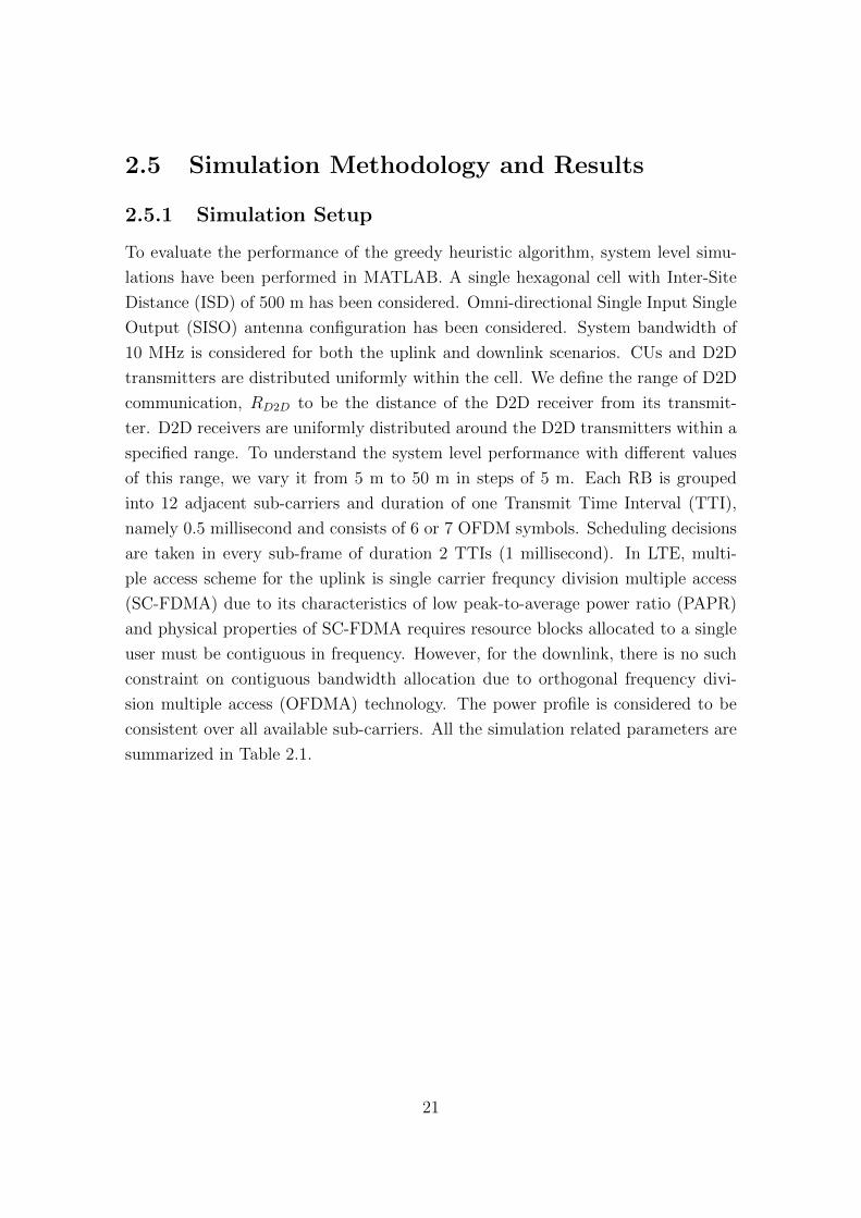
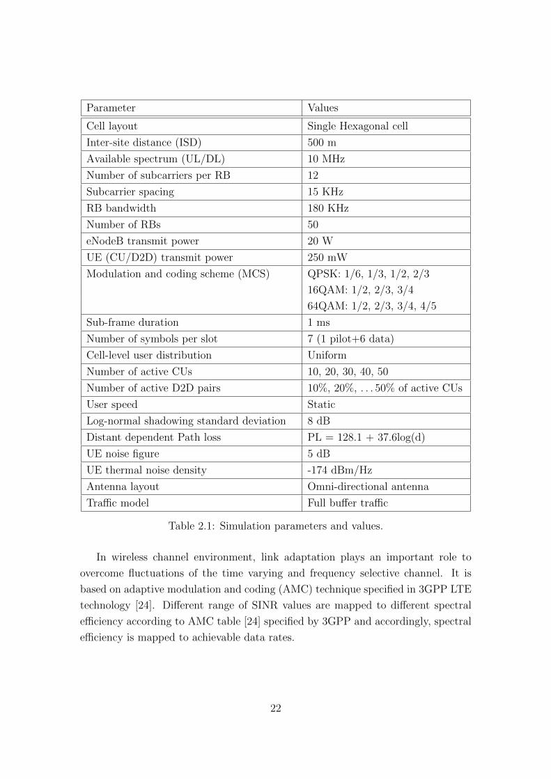
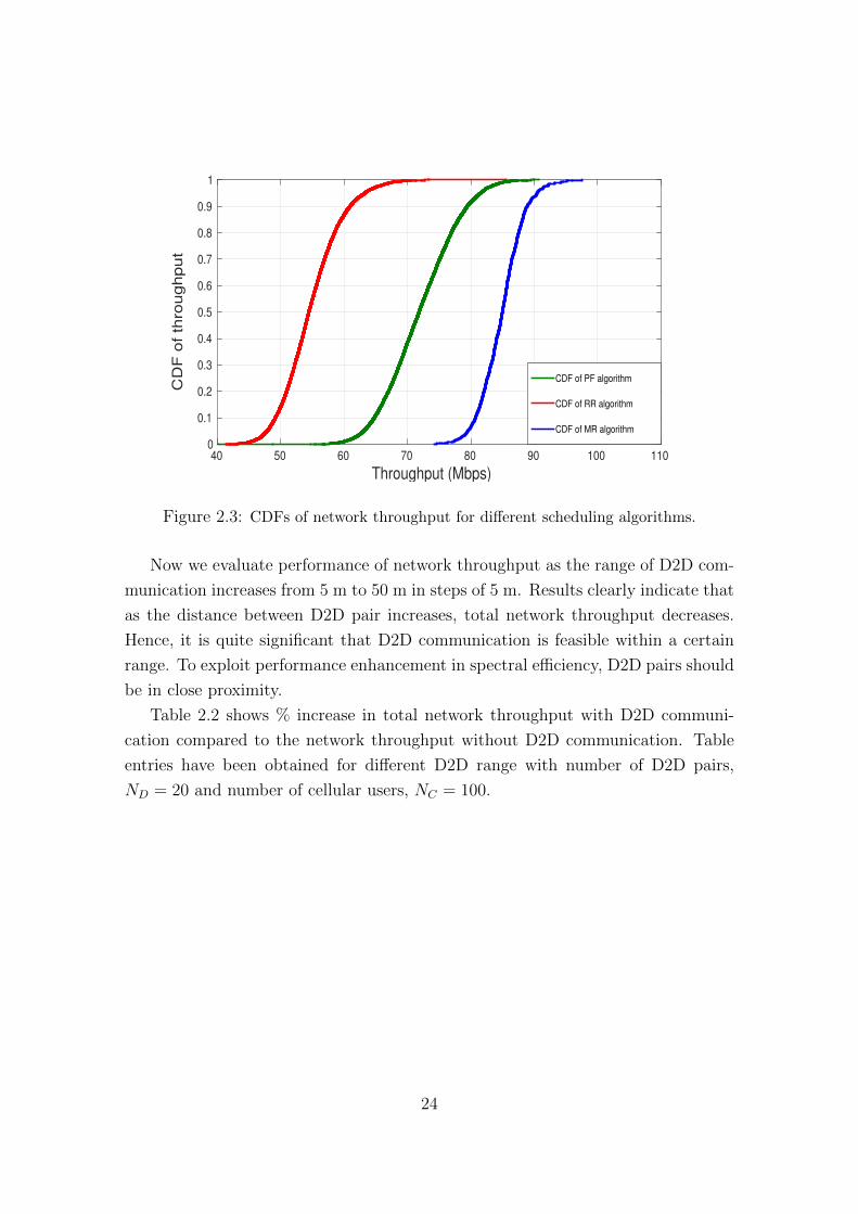
schedule D2D users. Simulation results have been presented in Section 2.5. Finally,
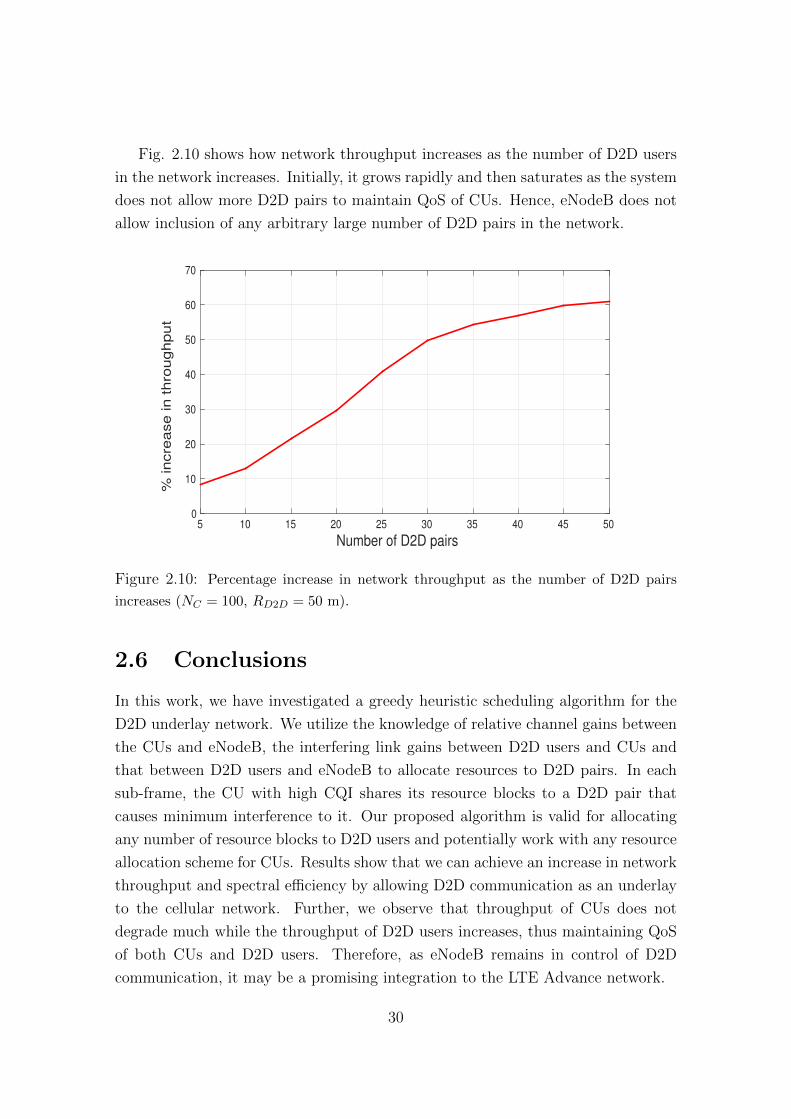
Section 2.6 concludes the chapter and provides directions of future work.
13
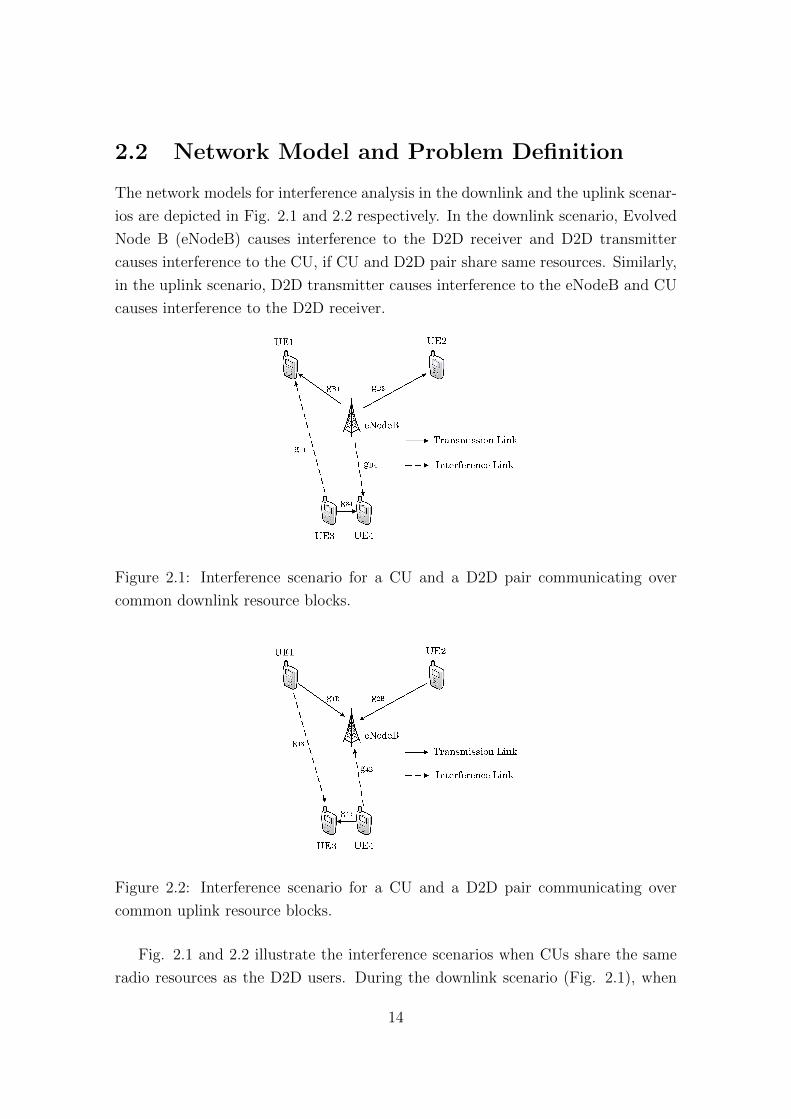
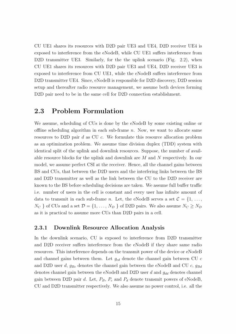
2.2 Network Model and Problem Definition
The network models for interference analysis in the downlink and the uplink scenar-
ios are depicted in Fig. 2.1 and 2.2 respectively. In the downlink scenario, Evolved
Node B (eNodeB) causes interference to the D2D receiver and D2D transmitter
causes interference to the CU, if CU and D2D pair share same resources. Similarly,
in the uplink scenario, D2D transmitter causes interference to the eNodeB and CU
causes interference to the D2D receiver.
Figure 2.1: Interference scenario for a CU and a D2D pair communicating over
common downlink resource blocks.
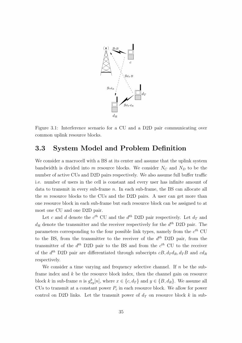
Figure 2.2: Interference scenario for a CU and a D2D pair communicating over
common uplink resource blocks.
Fig. 2.1 and 2.2 illustrate the interference scenarios when CUs share the same
radio resources as the D2D users. During the downlink scenario (Fig. 2.1), when
14
CU UE1 shares its resources with D2D pair UE3 and UE4, D2D receiver UE4 is
exposed to interference from the eNodeB, while CU UE1 suffers interference from
D2D transmitter UE3. Similarly, for the the uplink scenario (Fig. 2.2), when
CU UE1 shares its resources with D2D pair UE3 and UE4, D2D receiver UE3 is
exposed to interference from CU UE1, while the eNodeB suffers interference from
D2D transmitter UE4. Since, eNodeB is responsible for D2D discovery, D2D session
setup and thereafter radio resource management, we assume both devices forming
D2D pair need to be in the same cell for D2D connection establishment.
2.3 Problem Formulation
We assume, scheduling of CUs is done by the eNodeB by some existing online or
offline scheduling algorithm in each sub-frame n. Now, we want to allocate same
resources to D2D pair d as CU c. We formulate this resource allocation problem
as an optimization problem. We assume time division duplex (TDD) system with
identical split of the uplink and downlink resources. Suppose, the number of avail-
able resource blocks for the uplink and downlink are M and N respectively. In our
model, we assume perfect CSI at the receiver. Hence, all the channel gains between
BS and CUs, that between the D2D users and the interfering links between the BS
and D2D transmitter as well as the link between the CU to the D2D receiver are
known to the BS before scheduling decisions are taken. We assume full buffer traffic
i.e. number of users in the cell is constant and every user has infinite amount of
data to transmit in each sub-frame n. Let, the eNodeB serves a set C = {1, . . . ,
NC } of CUs and a set D = {1, . . . , ND } of D2D pairs. We also assume NC ≥ ND
as it is practical to assume more CUs than D2D pairs in a cell.
2.3.1 Downlink Resource Allocation Analysis
In the downlink scenario, CU is exposed to interference from D2D transmitter
and D2D receiver suffers interference from the eNodeB if they share same radio
resources. This interference depends on the transmit power of the device or eNodeB
and channel gains between them. Let gcd denote the channel gain between CU c
and D2D user d, gBc denotes the channel gain between the eNodeB and CU c, gBd
denotes channel gain between the eNodeB and D2D user d and gdd denotes channel
gain between D2D pair d. Let, PB, Pc and Pd denote transmit powers of eNodeB,
CU and D2D transmitter respectively. We also assume no power control, i.e. all the
15
transmit powers are fixed. Now, if the dth D2D pair shares same downlink resource
blocks as the CU c, the received SINR of the CU c is given by,
γDLc =PBgBc
N0 +∑
d xdcPdgcd
. (2.1)
Similarly, the received SINR at the dth D2D receiver is given by,
γDLd =
∑c x
dcPdgdd
N0 +∑
c xdcPBgBd
. (2.2)
Here, N0 denotes the thermal noise power spectral density at the receiver
and the optimization variable xdc is an indicator function defined as,
xdc =
{1, if D2D pair d shares resource blocks with CU c,
0, otherwise.
Let, rDLc and rDLd represent the rates corresponding to the SINRs γDLc and γDLdrespectively as determined by the Shannon’s Capacity Theorem. The goal here
is maximize total system sum throughput constrained on satisfying minimum rate
requirements of both CUs and D2D pairs. For simplicity, we assume maximum one
CU can share its resource blocks to one D2D pair and vice versa. Then, in the sub-
frame n, the resource allocation problem can be formulated [10] as an optimization
problem given as,
Maximize∑c
mcrDLc +
∑d
∑c
xdcmcrDLd , (2.3)
PBgBc ≥ γDLc,tgt
(N0 +
∑d
xdcPdgcd
), ∀c ∈ C, (2.4)
∑c
xdcPdgdd ≥ γDLd,tgt
(N0 +
∑c
xdcPBGBd
), ∀d ∈ D, (2.5)
∑c
xdc ≤ 1, ∀d ∈ D, (2.6)
16
and∑d
xdc ≤ 1, ∀c ∈ C. (2.7)
Here, mc denotes the number of downlink resource blocks allocated to the CU
c in sub-frame n. Also, γDLc,tgt and γDLd,tgt denote minimum target SINRs of CU c and
D2D pair d respectively. Equations 2.4 and 2.5 ensure maintaining minimum rate
requirements for both CU c and D2D pair d, while Equations 2.6 and 2.7 ensure
that one D2D pair can be allocated at most one CU’s resources and one CU can
share its resources to at most one D2D pair respectively.
2.3.2 Uplink Resource Allocation Analysis
In the uplink scenario, eNodeB is exposed to interference from D2D transmitter and
D2D receiver suffers interference from CU if they share same radio resources. Now,
if the dth D2D pair shares same uplink resource blocks as CU the c, the received
SINR at the eNodeB is given by,
γULB =PcgBc
N0 +∑
d ydcPdgBd
. (2.8)
Similarly, the received SINR at the dth D2D receiver is given by,
γULd =
∑c y
dcPdgdd
N0 +∑
c ydcPcGcd
. (2.9)
Here, the optimization variable ydc is an indicator function defined as,
ydc =
{1, if D2D pair d shares resource blocks with CU c,
0, otherwise.
Let, rULB and rULd represent the rates corresponding to the SINRs γULB and γULdrespectively as determined by the Shannon’s Capacity Theorem. The goal here
is maximize total system sum throughput constrained on satisfying minimum rate
requirements of both CUs and D2D pairs. For simplicity, we assume maximum one
CU can share its resource blocks to one D2D pair and vice versa. Then, in the sub-
frame n, the resource allocation problem can be formulated [10] as an optimization
problem given as,
17
Maximize∑c
ncrULB +
∑d
∑c
ydcncrULd , (2.10)
PcgBc ≥ γULB,tgt
(N0 +
∑d
ydcPdgBd
), ∀c ∈ C, (2.11)
∑c
ydcPdgdd ≥ γULd,tgt
(N0 +
∑c
ydcPcgcd
), ∀d ∈ D, (2.12)
∑c
ydc ≤ 1, ∀d ∈ D, (2.13)
and∑d
ydc ≤ 1, ∀c ∈ C. (2.14)
Here, nc denotes the number of uplink resource blocks allocated to CU c in
sub-frame n. Also, γULB,tgt and γULd,tgt denote the minimum target SINR of CU c and
D2D pair d respectively. Equations 2.11 and 2.12 ensure maintaining minimum rate
requirements for both CU c and D2D pair d, while Equations 2.13 and 2.14 ensure
that one D2D pair can be allocated at most one CU’s resources and one CU can
share its resources to at most one D2D pair respectively.
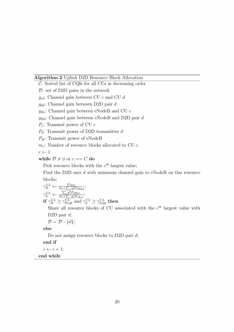
2.4 Greedy Scheduling Algorithm for D2D Users
The optimization problems formulated above for the downlink and uplink scenarios
are mixed integer non-linear programming (MINLP). Since, it is very difficult to a
get an optimal solution within a scheduling interval of 1 ms, we can use a subop-
timal greedy heuristic algorithm to allocate resources to D2D users. The proposed
algorithms are as follows:
For the downlink scenario, as we can observe from Equation 2.1, the lower the
channel gain between CU and D2D pair sharing same radio resources or larger
the channel gain between CU and eNodeB, higher the system sum throughput.
Therefore, intuitively, a CU with high channel quality indicator (CQI) can share its
resource blocks with a D2D pair, which causes minimum interference to that CU.
18
Similarly for the uplink scenario, we can observe from Equation 2.8, the lower
the channel gain between D2D pair and eNodeB or larger the channel gain between
CU and eNodeB sharing same radio resources, higher the system sum throughput.
Therefore, intuitively, a CU with high CQI can share its resource blocks with a D2D
pair which causes minimum interference to eNodeB on those resource blocks.
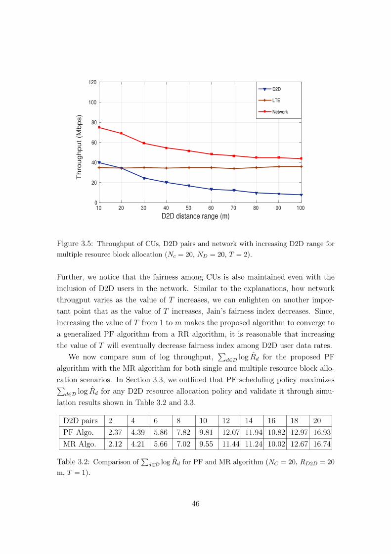
Further, we notice that the fairness among CUs is also maintained even with the
inclusion of D2D users in the network. Similar to the explanations, how network
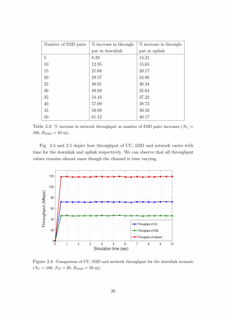
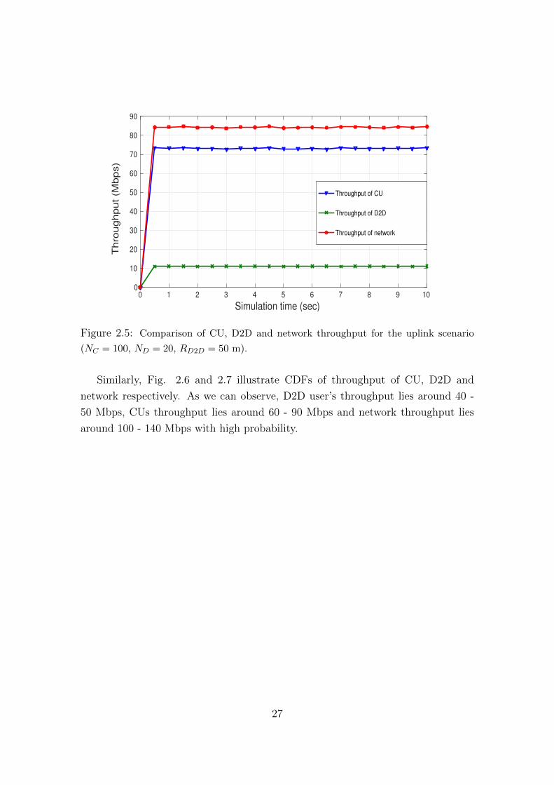
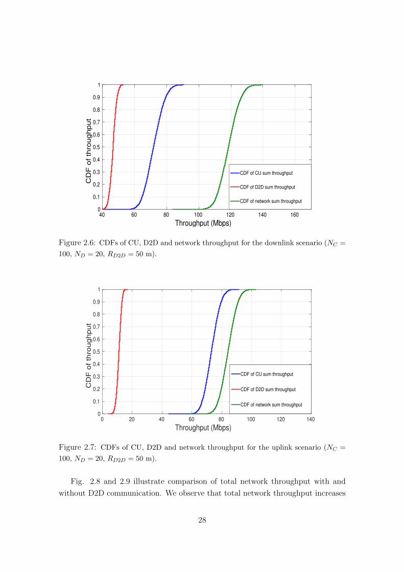
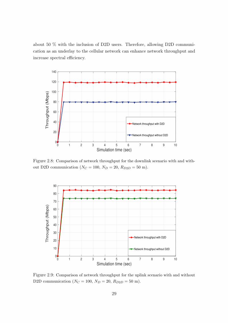
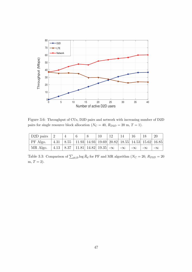
througput varies as the value of T increases, we can enlighten on another impor-
tant point that as the value of T increases, Jain’s fairness index decreases. Since,
increasing the value of T from 1 to m makes the proposed algorithm to converge to
a generalized PF algorithm from a RR algorithm, it is reasonable that increasing
the value of T will eventually decrease fairness index among D2D user data rates.
We now compare sum of log throughput,∑
d∈D log R̂d for the proposed PF
algorithm with the MR algorithm for both single and multiple resource block allo-
cation scenarios. In Section 3.3, we outlined that PF scheduling policy maximizes∑d∈D log R̂d for any D2D resource allocation policy and validate it through simu-