149
1143279 R04 ZL 10/31/2019 EN-DOM REF 1143279 Respironics Inc. 1001 Murry Ridge Lane Murrysville, PA 15668 USA Instructions for use Trilogy Evo Trilogy EV300

1143279 R04 ZL 10/31/2019
EN-DOM
REF 1143279
Respironics Inc.1001 Murry Ridge LaneMurrysville, PA 15668 USA
Instructions for use
Trilogy EvoTrilogy EV300

Trilogy EV300
Instructions for Use

For Technical Support and Customer Service, contact Philips Respironics Customer Service:
1-724-387-40001-800-345-6443 (toll-free)
USARespironics Inc.1001 Murry Ridge Lane Murrysville, PA 15668
Email: [email protected], [email protected] Web: www.philips.com\healthcare
Copyright © Koninkijke Philips N.V., 2019. All rights reserved.
This work is protected under Title 17 of the United States copyright code and is the sole property of Philips Respironics. No part of this document may be copied or otherwise reproduced, or stored in any electronic information retrieval system, except as specifically permitted under United States copyright law, without the prior written consent of Philips Respironics.
Trilogy EV300 is the registered trademark of Respironics Inc.
The Bluetooth® word mark and logos are registered trademarks owned by Bluetooth SIG, Inc. and any use of such marks by Philips Respironics is under license.
Dawn Ultra is a registered trademark of Procter & Gamble.
Other trademarks and trade names are those of their respective owners.
Illustrations and screen images in this document are representative depictions.
Contents
1. Introduction1.1 Overview ...............................................................................................................................................4
1.2 Device Usage .......................................................................................................................................4
1.3 Package Contents ..............................................................................................................................5
1.4 Warnings .............................................................................................................................................. 6
1.5 MRI Safety Information ...................................................................................................................11
1.6 Symbols Glossary..............................................................................................................................11
1.7 How to Contact Philips Respironics ............................................................................................ 13
2. About Trilogy EV3002.1 Overview ............................................................................................................................................. 14
2.2 Parts of Trilogy EV300 ................................................................................................................... 14
2.3 Parts of the User Interface............................................................................................................. 17
2.4 Monitoring Window .........................................................................................................................19
3. Therapy Modes and Controls3.1 Overview ............................................................................................................................................. 21
3.2 Therapy Modes Principles ............................................................................................................. 21
3.3 Control Modes ................................................................................................................................. 25
3.4 Spontaneous Modes ......................................................................................................................29
3.5 Mixed Modes .................................................................................................................................... 32
3.6 AVAPS-AE Mode ..............................................................................................................................37
3.7 Therapy Features ............................................................................................................................39
3.8 Therapy Control Settings .............................................................................................................. 42
3.9 Lung Parameters .............................................................................................................................44
4. Device Setup4.1 Overview ............................................................................................................................................48
4.2 Placement .........................................................................................................................................48
4.3 Connecting AC Power ....................................................................................................................48
4.4 Installing Filters ...............................................................................................................................49
4.5 Connecting a Circuit .......................................................................................................................49
4.6 Connecting External Patient Monitors ..................................................................................... 54
4.7 Adding Oxygen ................................................................................................................................ 54
4.8 Starting Trilogy EV300 ...................................................................................................................57

ii
Trilogy EV300 Instructions for Use
5. Device Operation5.1 Overview ............................................................................................................................................ 58
5.2 Clinical Assessment ........................................................................................................................ 58
5.3 Entering New Patient Information ............................................................................................. 58
5.4 About Prescriptions/Settings ......................................................................................................59
5.5 Starting and Stopping Therapy ....................................................................................................61
5.6 Actions During Ventilation .............................................................................................................61
6. Alarms and System Messages6.1 Overview ............................................................................................................................................64
6.2 About Alarms ....................................................................................................................................64
6.3 The Alarm List ..................................................................................................................................65
6.4 Setting and Changing Alarms ......................................................................................................66
6.5 Setting the Alarm Volume ............................................................................................................. 67
6.6 Responding to an Alarm ............................................................................................................... 67
6.7 Alarms and System Messages ....................................................................................................68
6.8 Patient-related Alarm Availability by Therapy Mode ............................................................91
6.9 Testing Alarms ..................................................................................................................................92
7. Device Options7.1 Overview ............................................................................................................................................ 97
7.2 Device Options................................................................................................................................. 97
7.3 Calibration .........................................................................................................................................98
7.4 Data Transfer ................................................................................................................................... 101
7.5 Information ..................................................................................................................................... 102
7.6 Alarm and Event Log .................................................................................................................... 103
8. Cleaning and Disinfection8.1 Overview .......................................................................................................................................... 105
8.2 Exterior Cleaning and Disinfection .......................................................................................... 105
8.3 Cleaning the Detachable Battery ............................................................................................. 109
8.4 Rinsing the Air-Inlet Foam Filter ............................................................................................... 110
9. Service and Maintenance9.1 Service Overview ............................................................................................................................. 111
9.2 Disposal ............................................................................................................................................. 111
9.3 Daily Maintenance .......................................................................................................................... 111
9.4 Replacing the Air-Inlet Foam Filter ........................................................................................... 111
9.5 Replacing the Particulate Filter ..................................................................................................112
9.6 Preparing the Device for Use by a Different Patient .............................................................113

iii
10. Accessories10.1 Overview ........................................................................................................................................... 114
10.2 Portability and Accessories ......................................................................................................... 114
10.3 Power Accessories ......................................................................................................................... 114
10.4 Patient Circuits and Circuit Accessories .................................................................................. 114
10.5 Monitors and Sensors ................................................................................................................... 116
10.6 Filters ..................................................................................................................................................117
10.7 Oxygen ...............................................................................................................................................117
10.8 Communications Cables ...............................................................................................................117
10.9 Remote Alarm and Nurse Call .................................................................................................... 118
10.10 USB Flash Drive .............................................................................................................................. 118
11. Power Management11.1 Overview ........................................................................................................................................... 119
11.2 AC Power .......................................................................................................................................... 119
11.3 External Battery.............................................................................................................................. 119
11.4 Detachable Battery ...................................................................................................................... 120
11.5 Internal Battery ................................................................................................................................121
11.6 Battery Status..................................................................................................................................122
11.7 Power Loss .......................................................................................................................................122
11.8 Power Icons......................................................................................................................................123
12. Connectivity12.1 Overview ...........................................................................................................................................124
12.2 External Systems ............................................................................................................................124
12.3 Wireless .............................................................................................................................................124
12.4 Connectivity Actions .....................................................................................................................125
13. Technical Data13.1 Overview .......................................................................................................................................... 126
13.2 Specifications ................................................................................................................................. 126
13.3 Pneumatic Diagram .......................................................................................................................132
14. Regulatory Information14.1 Standards Compliance .................................................................................................................133
14.2 EMC Information ............................................................................................................................134
14.3 Wireless ............................................................................................................................................ 139
14.4 Software Licensing ....................................................................................................................... 140
15. Glossary15.1 Glossary of Terms ........................................................................................................................... 141
Warranty .................................................................................................................................................... 146

1.1 OverviewThe Trilogy EV300 ventilator provides invasive and noninvasive, positive pressure ventilation to pediatric through adult patients with a minimum weight of 2.5 kg. It is an electronically controlled, pneumatic ventilation system with an integrated air compressing system. It is compatible with a range of accessories to provide a variety of therapy modes.
The Trilogy EV300 ventilator is a medical device intended for use by qualified, trained personnel under the direction of a physician according to its technical specifications. For training and support materials, see the Trilogy EV300 website:www.philips.com/EV300
1.2 Device Usage
1.2.1 Intended Use
The Trilogy EV300 ventilator provides continuous or intermittent positive pressure ventilation for the care of individuals who require mechanical ventilation. Trilogy EV300 is intended for pediatric through adult patients weighing at least 2.5 kg. The ventilator can measure, display, record, and alarm SpO2, FiO2, CO2, and Pulse Rate data when integrated with the appropriate accessories. The ventilator is suitable for use in institutional, home, and non-emergency transport settings for example wheelchair or personal vehicle. It may be used for both invasive and non-invasive ventilation.
1.2.2 Environments of Use
The Trilogy EV300 ventilator is intended to be used:
• In institutional environments.
• While attached to a roll stand or sitting on a flat surface such as a table or nightstand.
• While transporting patients within and between facilities, such as an automobile or commercial aircraft.
1. Introduction

5
1. Introduction
1.2.3 Contraindications
If the patient has any of the following conditions, consult the patient’s health care professional before using noninvasive ventilation:
• An inability to maintain a patent airway or adequately clear secretions• At risk to aspirate gastric contents• Acute sinusitis or otitis media• Epistaxis, causing pulmonary aspiration of blood• Hypotension
The AVAPS-AE therapy mode is contraindicated for invasive use and patients less than 10 kg.
The AVAPS feature is contraindicated for patients less than 10 kg.
1.2.4 Users
Clinical Users of the Trilogy EV300 ventilator include: clinicians (respiratory and non-respiratory) and physicians.
Service and Maintenance Users of the Trilogy EV300 ventilator include: hospital and service provider technicians.
1.3 Package ContentsPackage contents may vary based on model.
Instructions for UseUSB Flash Drive
AC Power Cord
ParticulateFilter
Flexible TrachAdapter
Dual LimbActive Exhalation Valve
Passive, Single Limb Circuit

6
Trilogy EV300 Instructions for Use
1.4 WarningsCaution: U.S. federal law restricts this device to sale by or on the order of a physician.
1.4.1 Environmental
• You should not operate the device in the presence of flammable gases.
• Do not cover the ventilator or place in a position that affects proper operation.
• Do not block the cooling and intake air vents.
• Do not operate the device in an environment that is outside the specified ranges. Using the ventilator outside of this temperature range or above this altitude can affect the device performance.
• Do not expose the device or detachable battery to temperatures above 60˚ C (140˚ F) during use or above 70˚C (158˚F) during storage. This will reduce battery life and may increase the risk of fire or damage the battery.
• Do not use the device within magnetic resonance (MR) environments. Using the device within MR environments may affect the device or MR device performance, damage the device, or harm individuals.
• Move the Trilogy EV300 device away from any potential sources of electromagnetic interference (EMI) including MRI equipment, medical imaging systems, security systems, appliances, wireless communications equipment (such as cellular phones), computers, and televisions.
• The device is not intended for anesthesia applications and is not intended to be permanently mounted in EMS vehicles.
• When disposing of this device or any accessories, ensure you comply with your local regulations. Dispose of any potentially biohazardous waste according to your local regulations.
• This device is intended for use in the electromagnetic environment specified in “EMC Information.” Ensure the environment is compatible. Portable and mobile RF communications equipment, including cables, should be no closer to any part of the device than the recommended separation distance indicated in “EMC Information.”
• This device is not made with natural rubber latex.
• Do not use the ventilator in a hyperbaric chamber.
• Do not use the ventilator in the presence of nitric or nitrous oxide.
• Do not use the ventilator with helium or in the presence of mixtures in combination with helium.
• Route all cables in a manner to prevent injury, such as tripping or strangulation, to the patient and caregiver.
• If the device has been stored at very high or very low temperatures, allow 2 hours for the device to reach ambient temperature before using. This allows adequate time for the battery to reach its operating temperature range for charging and discharging.
• This device is not defibrillation-proof.

7
1. Introduction
1.4.2 Clinical
• Before placing a patient on the ventilator, perform a clinical assessment. Considerations should include:
— Choosing alarm settings — Whether alternative ventilation equipment is required — Whether alternative monitors are required, such as Vte monitoring for Active PAP circuit, pulse
oximeter, respiratory monitor with alarm, SpO2, FiO2, EtCO2, and pulse rate
• Trilogy EV300 is a restricted medical device. It is designed for use by respiratory therapists or other trained and qualified caregivers under the supervision of a physician. Only the supervising physician’s orders authorize changes to the prescription and other device settings. Before using Trilogy EV300, you must read and understand this manual.
• The caregiver or health care professional is responsible for verifying any changes to the device, prescription, or other settings before applying changes. The caregiver or health care professional is responsible for ensuring settings are correct and compatible with the patient. Using the wrong prescription for a patient may result in improper therapy, lack of appropriate safety monitoring, or risk of death or injury to the patient.
1.4.3 Alternate Ventilation
• To avoid patient death or serious injury, ventilator-dependent patients require immediate access to alternate ventilation equipment, such as a back-up ventilator or manual resuscitator.
• Qualified personnel should monitor ventilator-dependent patients continuously. Personnel should be prepared to provide alternate therapy in the event of ventilator failure or inoperative equipment.
1.4.4 Alarms
• Do not rely on any single alarm to detect a disconnected circuit.
• Respond immediately to any high priority alarm. It may indicate a potentially life-threatening condition.
• Visually monitor the patient and ventilator at all times during an alarm silence period. Allowing alarms to continue without intervention may result in harm to the patient.
• If the high-priority, Low Battery alarm occurs, immediately connect the ventilator to an alternate power source. If no alternate power source is available, immediately place the patient on an alternate source of ventilation.
• When using a remote alarm or nurse call system, fully test the system by verifying that you can hear the ventilator’s audible alarms on the remote alarm or nurse call system.
• Test the operation of the circuit disconnect function daily and whenever the patient circuit is changed. An increase in circuit resistance can prevent proper operation of some alarms.

8
Trilogy EV300 Instructions for Use
• When adding any components to the breathing system, the flow resistance and dead space of the added components such as humidifiers, speaking valves, Heat Moisture Exchangers (HMEs) and filters should be carefully considered in relation to the potential for adverse effects on the patient’s ventilator management and device alarms.
• Do not set the Low Peak Inspiratory Pressure alarm too low, or the system may not detect large circuit leaks or a patient disconnect.
1.4.5 Accessories
• Use Trilogy EV300 only with accessories intended for use with this device. For a list of accessories, such as patient interfaces, circuits, exhalation ports, and cables, see the Trilogy EV300 accessories guide. Ensure accessories and parts are compatible before you connect a patient to the device. Consult the accessory’s instructions before use. Electronic accessories that are not intended for use with this device may cause adverse performance including: increased electromagnetic emissions or decreased electromagnetic immunity of this equipment.
• The air-inlet foam filter is required to protect the ventilator from dirt and dust. See the “Service and Maintenance” chapter for maintenance instructions.
• Be certain that any bacterial filter used with this device complies with ISO 23328-1 and ISO 23328-2. To prevent patient or ventilator contamination, you must use a Philips Respironics-approved main flow bacterial filter on the patient gas outlet port. Filters not approved by Philips Respironics may degrade system performance. For a list of accessories, see the Trilogy EV300 accessories guide.
• Nebulization or humidification can increase the resistance of bacterial filters. Monitor the breathing system frequently for increased resistance and blockage.
• Gas added by the use of a pneumatic nebulizer can adversely affect ventilator accuracy.
• When using a passive circuit an exhalation port is required.
• Do not use antistatic or conductive hoses or conductive patient tubing with the device.
• The ventilator system (used with patient circuit accessories, such as patient interface devices, humidifiers, water traps, and circuit tubing) may contain small parts that could result in a choking hazard.
• Be certain that any humidifier in use, including any heated breathing tube, complies with ISO 8185 or ISO 80601-2-74.
• Be certain that any heat and moisture exchanger in use complies with ISO 9360-1 or ISO 9360-2.
• Only connect devices recommended by Philips Respironics to the USB ports. Connecting other devices could result in patient injury or damage to the ventilator.
• The Micro USB port is for service personnel only.

9
1. Introduction
1.4.6 Oxygen
1.4.6.1 High Pressure Oxygen
• This device is equipped with an oxygen blender that can deliver oxygen to the patient within a range of 21-100% concentration.
• When using the oxygen blender, use the internal FiO2 accessory to verify the oxygen concentration in the delivered gas.
• Substantial leaks may reduce the inspired oxygen concentration to less than the expected value. Use appropriate patient monitoring, as medically indicated, such as an alarming pulse oximeter.
• Do not connect the device to an unregulated oxygen source.
• Do not use oxygen while smoking or in the presence of an open flame.
1.4.6.2 Low Flow Oxygen
• Do not use oxygen while smoking or in the presence of an open flame.
• Turn off the low flow oxygen when the device is not in use.

10
Trilogy EV300 Instructions for Use
1.4.7 Cleaning and Maintenance
• To avoid electric shock, do not remove the enclosure cover. Only service personnel should remove the enclosure.
• Do not immerse the device or allow liquids into any of the controls or the interior of the enclosure as the device may be damaged. If this occurs, contact your equipment provider for assistance. Use only the agents and methods described in this manual to clean and disinfect the device. After cleaning and disinfecting, ensure the device is completely dry before reattaching accessories and connectors and before reconnecting it to a power source. Do not use solvents, polishes, or any oily substances on the device, as they are flammable.
• If the device has been exposed to rain or dampness, dry the device including the area around the power cord connection with the power cord disconnected from the device before applying AC power.
• Repairs and adjustments must be performed by service personnel only. Unauthorized repairs and adjustments could cause death or injury, invalidate the warranty, or result in costly device damage.
• If you notice any unexplained changes in the performance of the device, if it is making unusual sounds, if the device or detachable battery is dropped, if water is spilled into the enclosure, or if the enclosure is cracked or broken, discontinue use and contact Philips Respironics.
• To avoid electrical shock, always unplug the power cord from the wall outlet before cleaning the ventilator.
• Periodically inspect electrical cords, cables, and the detachable battery pack for damage or signs of wear. Discontinue use and replace if damaged.
• Any changes or modifications made to the device that are not expressly approved by Philips Respironics may void the user’s authority to operate the equipment.
1.4.8 Power
• An external battery should only be connected to the ventilator using the Philips Respironics approved External Battery Cable. This cable is fused, pre-wired, and properly terminated to ensure safe connection.
• Use only the Philips Respironics Detachable Battery.

11
1. Introduction
1.5 MRI Safety Information The Trilogy EV300 Ventilation System is MR Unsafe. Keep it outside the MRI scan room (Zone IV). It represents a projectile hazard.
1.6 Symbols GlossarySee http://www.symbols.philips.com for a description of the symbols used on this device and its packaging.
Symbol Definition Symbol DefinitionSymbols on the Device Label and Package Label
Refer to instruction manual Date of manufacture
For airline use. Complies with RTCA DO-160G section 21, category M
Class II equipment
Bluetooth® symbol Type BF applied part
IP22
IP22: protection against finger-sized objects and protected against dripping water when tilted up to 15 degrees.
Serial number
Catalog number Humidity limit
Batch code Temperature limit
Manufacturer MR unsafe
Symbols on the Device
On/Off (Standby) button Low flow oxygen inlet
Alarm Silence button Flow sensor cable connection
USB port Proximal pressure out
Nurse call connection AEV control line

12
Trilogy EV300 Instructions for Use
Symbol Definition Symbol Definition
DC power (direct current) Patient in
AC power (alternating current) Patient out
41-87 psi(280-600 kPa)
1-150 l/min
Oxygen inlet
Symbols on the Screen - General
Prescription settings Deliver 100% oxygen
Home window Delete prescription
Options Touch screen lock
Help Edit
Device actions menu
Symbols on the Screen - Alarms
Alarms tab
Medium or low priority alarm
2:00Alarm silence
System message
High priority alarm Reset Alarm reset
Symbols on the Screen - Connectivity
Bluetooth data transfer USB data transfer
Symbols on the Screen – Monitoring ViewsSee “Monitoring Window” section Symbols on the Screen - Power See “Power Icons” section

13
1. Introduction
1.7 How to Contact Philips RespironicsIf you need help setting up, using, or maintaining Trilogy EV300, or if this device does not perform as expected, contact Philips Respironics.
Call Philips Respironics Customer Service at:
• 1-724-387-4000
• 1-800-345-6443 (toll-free)
Respironics, Inc.1001 Murry Ridge LaneMurrysville, PA 15668

2.1 OverviewThis chapter describes the physical parts of the device and the parts of the user interface.
2.2 Parts of Trilogy EV300
2.2.1 Front Panel
4
1
3
62
5
1. On/Off (Standby) button
2. AC power indicator
3. Alarm Silence button/alarm indicator
4. Alarm bar
5. Touch screen
6. Ambient light sensor
2. About Trilogy EV300

15
2. About Trilogy EV300
2.2.2 Back Panel with Oxygen Blending Module
3
65
2
1
74
1. Carrying handle
2. FiO2 sensor access panel
3. Power cord retention clip
4. Air vents
5. Air inlet
6. Oxygen blender
7. High pressure oxygen inlet
2.2.3 Patient Panel
1
3
6
2
4
5
1. USB port
2. Inspiratory port (to patient)
3. Proximal pressure port
4. Active exhalation valve line connection for ActivePAP and Active Flow circuits
5. Dual limb active exhalation valve con-nection (from patient)
6. Flow sensor cable connector

16
Trilogy EV300 Instructions for Use
2.2.4 Utility Panel
6
7
8
3
4
2
1
52
1. AC power connector
2. Air vents
3. Low flow oxygen inlet
4. Detachable battery access door
5. Micro USB port for device service only
6. USB port
7. Remote alarm or nurse call connector (RJ9)
8. DC power connector

17
2. About Trilogy EV300
2.3 Parts of the User Interface
2.3.1 Standard Screen Elements
11:27am
StandbyNot Ventilating
AdultAVAPS-AE Passive
Prescription 11
2
3
4
Adult
These standard elements appear on most screens.
1. Menu bar
2. Workspace
3. Status Bar
4. Monitored parameters pane
2.3.2 Menu Bar
StandbyNot Ventilating
AdultAVAPS-AE Passive
Prescription 1
1 2 3 4 5
Use the menu bar to navigate, manage alarms, set device options, and see the active prescription.
The menu bar has the following parts.
1. Tap the Home button to go to the home window.
2. Tap the Prescription Settings button to work with prescriptions.
3. Tap the Options button to work with device options.
4. View the patient type.
5. When in the home window, tap the Prescription List to see a list of prescriptions.

18
Trilogy EV300 Instructions for Use
2.3.3 Workspace
The workspace contents vary depending on the action you are performing, For example, the workspace can show the standby window, prescription window, or monitoring window.
2.3.4 Monitored Parameters Pane
505 mL
Vte
14 BPM
RR
7.1 L/min
MinVent
27.8 cmH2O
PIP
99 %
SpO2
The monitored parameters pane shows values while delivering therapy. Depending on the accessory, values such as SpO2 and pulse rate appear during ventilation and standby.
Parameters that may appear are:
— EtCO2: end tidal carbon dioxide — FiO2: fraction of inspired oxygen — MinVent: minute ventilation — PIP: peak inspiratory pressure — PR: pulse rate — RR: respiratory rate — SpO2: saturation of peripheral oxygen — Vte: exhaled tidal volume — Vti: inhaled tidal volume
2.3.5 Status Bar
10:52am2:002:00
1 2 3 4 5 6 7 8 109
Use the status bar to monitor device status and the availability of manual therapeutic actions.
1 Deliver 100% Oxygen 6 Bluetooth data transfer
2 100% Oxygen timer 7 Alarm silence
3 Automatic algorithm restart 8 Power sources and their status
4 Full access indicator 9 Device Actions menu
5 Bluetooth 10 System time

19
2. About Trilogy EV300
2.4 Monitoring WindowDuring ventilation, you can view different types of data. In the home window, the Views list shows the data types. Use the list to select the data you want to see.
2.4.1 Selecting a Monitoring View
To select a monitoring view, follow these steps.
1. In the Menu Bar, tap the Home button.
2. In the home window, tap the Views button.
Views
3. In the Views list, tap the view you want to use.

20
Trilogy EV300 Instructions for Use
2.4.2 Types of Monitoring Windows
Views list icon Monitoring window contents
Small manometer
• Small manometer pressure indicator• Breath indicator: When the current breath is triggered by the patient, the
circle next to the manometer changes from light green to dark green.• Set parameters
Large manometer with parameters
• Large manometer pressure indicator• Breath indicator: When the current breath is triggered by the patient, the
circle next to the manometer changes from light green to dark green.• Six measured and calculated parameters
Measured and calculated
parameters
• Set parameters• Measured and calculated parameters • Additional parameters based on the prescription (including accessories)
Customizable waveform graphs
To customize the graphs, use the buttons in the window as follows:
Button Description
Select the waveforms to graph. On the Select Waveforms dialog box, select data for the top and bottom graphs.
Pause graphing.
Automatically size the vertical scale to fit the data.
6 sTap to change the time scale, and then select a new time scale from the list.

This chapter describes the therapy modes and controls.
3.1 OverviewWaveform illustrations in this chapter are to illustrate therapy mode behavior and appear different from waveforms as they appear in the monitoring window. For information on monitoring views, see section “2.4 Monitoring Window.”
3.2 Therapy Modes Principles
3.2.1 Breath Types
Trilogy EV300 can deliver the following breath types:
• Mandatory: Ventilator-initiated, time-cycled• Assist-Control: Patient-initiated, time-cycled• Spontaneous: Patient-initiated, patient-cycled• Automatic Backup: See “AVAPS-AE Mode” for more details
3.2.2 Triggering and Cycling
3.2.2.1 Patient triggers
Auto-Trak is a combination of multiple flow triggering algorithms. The parameters of the algorithms are automatically set to synchronize the therapy with a variety of patients.
Sensitive Auto-Trak is a more sensitive version of Auto-Trak.
Flow trigger initiates a breath when the patient’s inspiratory effort creates a flow equal to or greater than the trigger sensitivity setting. A lower number is more sensitive. As inspiratory flow begins to decrease, the device cycles to expiration when the patient flow is less than the percentage of peak flow, based on the flow-cycle sensitivity setting.
3.2.3 Ventilator trigger
The ventilator trigger is time-based, defined by the Breath Rate setting.
3. Therapy Modes and Controls

22
Trilogy EV300 Instructions for Use
3.2.3.1 Flow patterns
Ramp wave pattern: airflow starts high and decreases throughout inspiration of the breath.
FLOW
TIME
Square wave pattern: airflow is generally constant throughout inspiration of the breath.
FLOW
TIME
3.2.4 Low Tidal Volume Therapy
3.2.4.1 Volume Control Modes
The following volume modes are available for patients who require a tidal volume down to 35 ml:
• A/C-VC• SIMV-VC
When setting volumes that are greater than or equal to 50 ml, use any circuit type (passive, active PAP, active flow, or dual limb).
When setting volumes that are less than 50 ml, use either the active flow or dual limb circuit type with the infant/pediatric external flow sensor. See the instructions included with the sensor.

23
3. Therapy Modes and Controls
3.2.4.2 Pressure Control Modes
The following pressure modes are available for patients who require a tidal volume less than 35 ml:
• A/C-PC• PSV• CPAP• S/T • SIMV-PC
In pressure control modes with tidal volumes less than 35 ml, use either the active flow or dual limb circuit type with the infant/pediatric external flow sensor. See the instructions included with the sensor.
3.2.5 Suctioning During Therapy
During closed-circuit suctioning, the ventilator does not restrict therapy modes or prescription settings.

24
Trilogy EV300 Instructions for Use
3.2.6 Therapy Mode Comparison Table
For all modes, the breath type varies based on time of patient inspiration. The breath type is always ventilator-initiated and mandatory when the Trigger Type is set to Off.
Mode Breath Type Trigger Source Inspiration Cycle Exhalation
Control Modes
A/C-PCAssist-Control Patient PEEP +
Pressure ControlInspiratory Time PEEP
Mandatory Ventilator
A/C-VCAssist-Control Patient
Tidal Volume Inspiratory Time PEEPMandatory Ventilator
Spontaneous Modes
CPAP Spontaneous Patient CPAP Patient CPAP
PSV Spontaneous Patient PEEP + Pressure Support
Patient PEEP
Mixed Modes
S/T Spontaneous Patient
IPAPPatient
EPAPMandatory Ventilator Inspiratory Time
SIMV-PC
Spontaneous Patient PEEP + Pressure Support
Patient
PEEPAssist-Control Patient PEEP +
Pressure ControlInspiratory Time
Mandatory Ventilator
SIMV-VC
Spontaneous Patient PEEP + Pressure Support
Patient
PEEPAssist-Control Patient
Tidal Volume Inspiratory TimeMandatory Ventilator

25
3. Therapy Modes and Controls
Mode Breath Type Trigger Source Inspiration Cycle Exhalation
AVAPS-AE Modes
AVAPS-AEPC Breathenabled
Assist-Control Patient AVAPS(Pressure Control based on set tidal volume)
Inspiratory TimeEPAP(variable based on airway resistance)
Mandatory Ventilator
AVAPS-AEPC Breathdisabled
Spontaneous Patient AVAPS(Pressure Support based on set tidal volume)
Patient
Mandatory Ventilator Inspiratory Time
AVAPS-AEPC Breathenabled
Auto-Backup
Ventilator(After the patient completes exhalation)
Pressure Control (variable based on the target volume and pressure)
Patient (see AVAPS-AE mode section for more details)
EPAP(variable based on airway resistance)
AVAPS-AEPC Breathdisabled
Pressure Support (variable based on the target volume and pressure)
3.3 Control Modes
3.3.1 A/C-PC: Assisted/Control-Pressure Control
3.3.1.1 Description
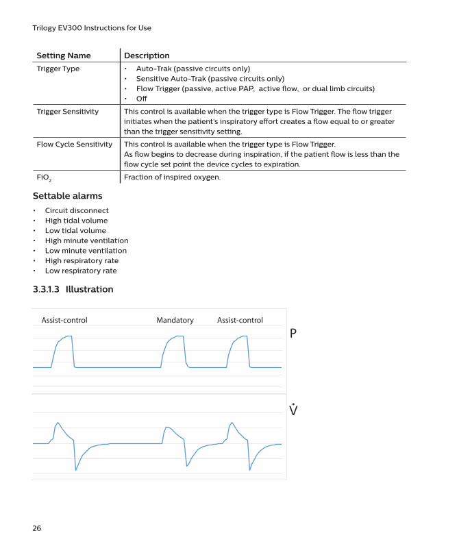
The A/C-PC mode provides pressure-controlled mandatory or assist-control breaths. When the Trigger Type is set to Off, the ventilator triggers and cycles all breaths. When the Trigger Type is not set to Off, then the ventilator or the patient can trigger a breath, and the ventilator cycles all breaths.
3.3.1.2 Settings
Setting Name Description
Pressure Control Inspiratory pressure above PEEP
PEEP Positive end expiratory pressure
Rise Time Time required for the ventilator to change from the expiratory pressure setting to the inspiratory pressure setting when the breath is triggered.
Breath Rate Minimum rate of mandatory breaths per minute
Inspiratory Time Length of the inspiratory phase
26
Trilogy EV300 Instructions for Use
Setting Name Description
Trigger Type • Auto-Trak (passive circuits only)• Sensitive Auto-Trak (passive circuits only)• Flow Trigger (passive, active PAP, active flow, or dual limb circuits)• Off
Trigger Sensitivity This control is available when the trigger type is Flow Trigger. The flow trigger initiates when the patient’s inspiratory effort creates a flow equal to or greater than the trigger sensitivity setting.
Flow Cycle Sensitivity This control is available when the trigger type is Flow Trigger.As flow begins to decrease during inspiration, if the patient flow is less than the flow cycle set point the device cycles to expiration.
FiO2 Fraction of inspired oxygen.
Settable alarms
• Circuit disconnect• High tidal volume• Low tidal volume• High minute ventilation• Low minute ventilation• High respiratory rate• Low respiratory rate
3.3.1.3 Illustration
Pressure
Flow
MandatoryAssist-control Assist-control
P
V�

27
3. Therapy Modes and Controls
3.3.2 A/C-VC: Assisted/Control-Volume Control
3.3.2.1 Description
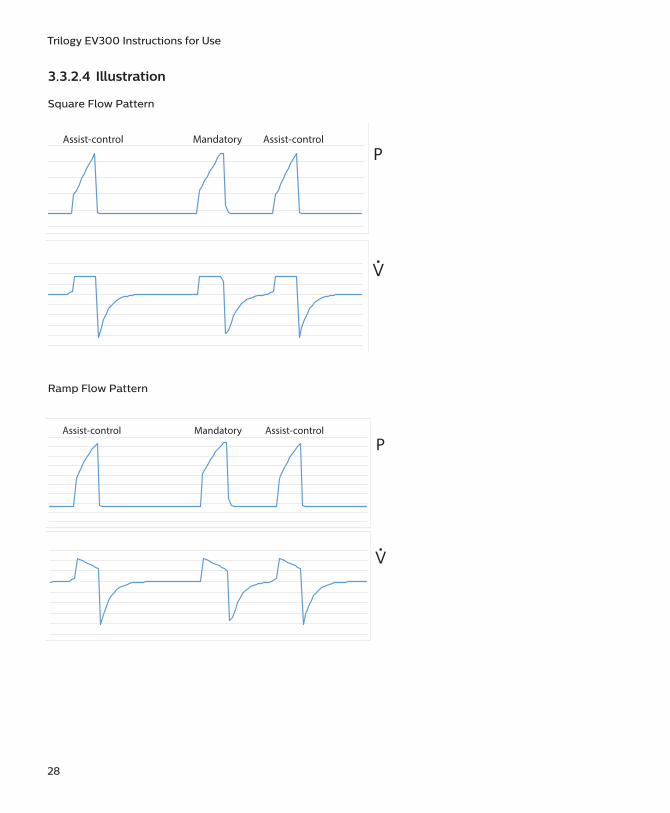
The A/C-VC mode provides volume-controlled mandatory or assist-control breaths. When the Trigger Type is set to Off, the ventilator triggers and cycles all breaths. When the Trigger Type is not set to Off, then the ventilator or the patient can trigger a breath, and the ventilator cycles all breaths. To deliver the set volume in the set time, the ventilator alters the flow rate. The flow pattern setting defines the shape of the flow delivery pattern.
3.3.2.2 Settings
Setting Name Description
Tidal Volume Set inspiratory volume
PEEP Positive end expiratory pressure
Inspiratory Time Length of the inspiratory phase
Breath Rate Minimum rate of mandatory breaths per minute
Flow Pattern Sets the shape of the waveform as a ramp or square
Trigger Type • Auto-Trak (passive circuits only)• Sensitive Auto-Trak (passive circuits only)• Flow Trigger (passive, active PAP, active flow, or dual limb circuits)• Off
Trigger Sensitivity This control is available when the trigger type is Flow Trigger. The flow trigger initiates when the patient’s inspiratory effort creates a flow equal to or greater than the trigger sensitivity setting.
Flow Cycle Sensitivity
This control is available when the trigger type is Flow Trigger.As flow begins to decrease during inspiration, if the patient flow is less than the flow cycle set point, the device cycles to expiration.
FiO2 Fraction of inspired oxygen.
3.3.2.3 Settable alarms
• Circuit disconnect• High tidal volume• Low tidal volume• High minute ventilation• Low minute ventilation• High respiratory rate• Low respiratory rate• High inspiratory pressure• Low inspiratory pressure
28
Trilogy EV300 Instructions for Use
3.3.2.4 Illustration
Square Flow Pattern
-100-80-60-40-20
0204060
Assist-control Mandatory Assist-control
P
V�
Ramp Flow Pattern
-100
-80
-60
-40
-20
0
20
40
60
MandatoryAssist-control Assist-control
P
V�

29
3. Therapy Modes and Controls
3.4 Spontaneous Modes
3.4.1 CPAP: Continuous Positive Airway Pressure
3.4.1.1 Description
In CPAP mode, the pressure delivered to the patient during both inhalation and exhalation is the CPAP pressure setting. All breaths in this mode are spontaneous breaths.
3.4.1.2 Settings
Setting Name Description
CPAP Continuous positive airway pressure range
Trigger Type • Auto-Trak (passive circuits only)• Sensitive Auto-Trak (passive circuits only)• Flow Trigger (passive, active PAP, active flow, or dual limb circuits)
Trigger Sensitivity This control is available when the trigger type is Flow Trigger. The flow trigger initiates when the patient’s inspiratory effort creates a flow equal to or greater than the trigger sensitivity setting.
Flow Cycle Sensitivity
This control is available when the trigger type is Flow Trigger. As flow begins to decrease during inspiration, if the patient flow is less than the flow cycle set point, the device cycles to expiration.
FiO2 Fraction of inspired oxygen.
3.4.1.3 Settable alarms
• Circuit disconnect• High tidal volume• Low tidal volume• High minute ventilation• Low minute ventilation• High respiratory rate• Low respiratory rate• Apnea alarm (requires backup ventilation)

30
Trilogy EV300 Instructions for Use
3.4.1.4 Illustration
5
5.5
6
6.5
7
7.5
8
8.5
9
9.5
10Spontaneous Spontaneous
P
V�
3.4.2 PSV: Pressure Support Ventilation
3.4.2.1 Description
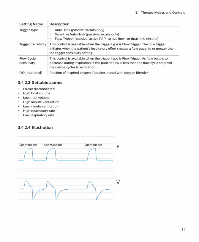
PSV mode is patient-triggered, pressure-limited, and flow-cycled. With this strategy, breaths are assisted by a set inspiratory pressure that is delivered until inspiratory flow drops below a set threshold.
In the PSV mode, the ventilator delivers spontaneous, pressure-supported, breaths and patient initiated breaths. The ventilator functions as a demand flow system, with the patient triggering breaths and determining their timing and volume. The ventilator can support the breaths with the set pressure support.
The Pressure Support setting defines the applied pressure above PEEP. The patient determines the breath timing. It is recommended that you set backup ventilation in PSV mode.
3.4.2.2 Settings
Setting Name Description
Pressure Support Pressure that the device delivers during the inspiratory phase of a spontaneous breath
PEEP Positive end expiratory pressure
Rise Time Time required for the ventilator to change from the expiratory pressure setting to the inspiratory pressure setting when the breath is triggered. May impact patient comfort and volume delivered.
31
3. Therapy Modes and Controls
Setting Name Description
Trigger Type • Auto-Trak (passive circuits only)• Sensitive Auto-Trak (passive circuits only)• Flow Trigger (passive, active PAP, active flow, or dual limb circuits)
Trigger Sensitivity This control is available when the trigger type is Flow Trigger. The flow trigger initiates when the patient’s inspiratory effort creates a flow equal to or greater than the trigger sensitivity setting.
Flow Cycle Sensitivity
This control is available when the trigger type is Flow Trigger. As flow begins to decrease during inspiration, if the patient flow is less than the flow cycle set point, the device cycles to expiration.
FiO2 (optional) Fraction of inspired oxygen. Requires model with oxygen blender.
3.4.2.3 Settable alarms
• Circuit disconnected• High tidal volume• Low tidal volume• High minute ventilation• Low minute ventilation• High respiratory rate• Low respiratory rate
3.4.2.4 Illustration
-40-30-20-10
0102030
Spontaneous Spontaneous Spontaneous P
V�

32
Trilogy EV300 Instructions for Use
3.5 Mixed Modes
3.5.1 S/T: Spontaneous/Timed
3.5.1.1 Description
A bi-level therapy mode where each breath is patient-triggered and patient-cycled, or ventilator-triggered and ventilator-cycled. In this mode, an IPAP is delivered during inhalation and a lower EPAP is delivered during exhalation. The duration of a spontaneous breath is determined by the patient effort. The duration of a mandatory breath is determined by the inspiratory time setting. Remember that the IPAP setting is the maximum pressure the ventilator will deliver; it is not in addition to the EPAP setting.
3.5.1.2 Settings
Setting Name Description
IPAP Inspiratory positive airway pressure. Must be greater than or equal to EPAP
EPAP Expiratory positive airway pressure
Rise Time Time required for the ventilator to change from the expiratory pressure setting to the inspiratory pressure setting when the breath is triggered. May impact patient comfort and volume delivered.
Breath Rate Minimum rate of breaths per minute. If the patient doesn’t trigger a breath within this time, the ventilator triggers the breath.
Inspiratory Time For a mandatory breath, length of the inspiratory phase
Trigger Type • Auto-Trak (passive circuits only)• Sensitive Auto-Trak (passive circuits only)• Flow Trigger (passive, active PAP, active flow, or dual limb circuits)
Trigger Sensitivity This control is available when the trigger type is Flow Trigger. The flow trigger initiates when the patient’s inspiratory effort creates a flow equal to or greater than the trigger sensitivity setting.
Flow Cycle Sensitivity
This control is available when the trigger type is Flow TriggerAs flow begins to decrease during inspiration, if the patient flow is less than the flow cycle set point, the device cycles to expiration.
FiO2 Fraction of inspired oxygen.
3.5.1.3 Settable alarms
• Circuit disconnect• High tidal volume• Low tidal volume• High minute ventilation• Low minute ventilation• High respiratory rate• Low respiratory rate

33
3. Therapy Modes and Controls
3.5.1.4 Illustration
P
V�
SpontaneousMandatoryMandatory
3.5.2 SIMV-PC: Synchronous Intermittent Mandatory Ventilation- Pressure Control
3.5.2.1 Description
SIMV-PC mode is a pressure control mode that provides a mixture of mandatory, assist-control and spontaneous breaths. SIMV-PC mode guarantees one mandatory breath in each cycle. Spontaneous breaths can be delivered with pressure support. The breath rate determines the length of the cycle. The first phase of the cycle is reserved for synchronizing a mandatory breath with patient effort. If the patient triggers a breath during this phase of the cycle, the ventilator delivers a synchronized mandatory breath also referred to as an assist-control breath. If a patient does not trigger a breath during the mandatory phase of the cycle, then the ventilator delivers a mandatory breath. Breaths triggered by the patient after the mandatory breath in the cycle are spontaneous breaths. This process is repeated at the start of every cycle.

34
Trilogy EV300 Instructions for Use
3.5.2.2 Settings
Setting Name Description
Pressure Control Defines the applied pressure above PEEP for mandatory and assist-control breaths
Pressure Support Defines the applied pressure above PEEP for spontaneous breaths
PEEP Positive end expiratory pressure Positive pressure maintained in the patient circuit during exhalation: must be less than or equal to the pressure setting.
Inspiratory Time For a mandatory breath, length of the inspiratory phase
Rise Time Time required for the ventilator to change from the expiratory pressure setting to the inspiratory pressure setting when the breath is triggered. May impact patient comfort and volume delivered.
Breath Rate Minimum rate of mandatory breaths per minute
Trigger Type • Auto-Trak (passive circuits only)• Sensitive Auto-Trak (passive circuits only)• Flow Trigger (passive, active PAP, active flow, or dual limb circuits)
Trigger Sensitivity This control is available when the trigger type is Flow Trigger. The flow trigger initiates when the patient’s inspiratory effort creates a flow equal to or greater than the trigger sensitivity setting.
Flow Cycle Sensitivity
This control is available when the trigger type is Flow Trigger. As flow begins to decrease during inspiration, if the patient flow is less than the flow cycle set point, the device cycles to expiration.
FiO2 Fraction of inspired oxygen.
3.5.2.3 Settable alarms
• Circuit disconnect• High tidal volume• Low tidal volume• High minute ventilation• Low minute ventilation• High respiratory rate• Low respiratory rate• Apnea alarm (requires backup ventilation)

35
3. Therapy Modes and Controls
3.5.2.4 Illustration
-80
-60
-40
-20
0
20
40
60
assist spont assist
Spontaneous
Assist-control Assist-control Mandatory Mandatory
P
V�
3.5.3 SIMV-VC: Synchronous Intermittent Mandatory Ventilation- Volume Control
3.5.3.1 Description
Similar to SIMV-PC, but with volume control.
3.5.3.2 Settings
Setting Name Description
Tidal Volume Gas volume that the device delivers during mandatory and assist-controlled breaths
Pressure Support Pressure that the device delivers during the inspiratory phase of a spontaneous breath
PEEP Positive end expiratory pressurePositive pressure maintained in the patient circuit during exhalation: must be less than or equal to the pressure setting.
Inspiratory Time For a mandatory breath, length of the inspiratory phase
Rise Time Time required for the ventilator to change from the expiratory pressure setting to the inspiratory pressure setting when the breath is triggered. May impact patient comfort and volume delivered.
Breath Rate Minimum rate of mandatory breaths per minute
Flow Pattern Sets the flow-pressure waveform

36
Trilogy EV300 Instructions for Use
Setting Name Description
Trigger Type • Auto-Trak (passive circuits only)• Sensitive Auto-Trak (passive circuits only)• Flow Trigger (passive, active PAP, active flow, or dual limb circuits)
Trigger Sensitivity This control is available when the trigger type is Flow Trigger. The flow trigger initiates when the patient’s inspiratory effort creates a flow equal to or greater than the trigger sensitivity setting.
Flow Cycle Sensitivity
This control is available when the trigger type is Flow TriggerAs flow begins to decrease during inspiration, if the patient flow is less than the flow cycle set point, the device cycles to expiration.
FiO2 Fraction of inspired oxygen.
3.5.3.3 Settable alarms
• Circuit disconnect• High tidal volume• Low tidal volume• High minute ventilation• Low minute ventilation• High respiratory rate• Low respiratory rate• High inspiratory pressure• Low inspiratory pressure• Apnea alarm (requires backup ventilation)
3.5.3.4 Illustration
-80
-60
-40
-20
P
V�
Spontaneous
Assist-control Mandatory Mandatory

37
3. Therapy Modes and Controls
3.6 AVAPS-AE Mode
3.6.1 AVAPS-AE
3.6.1.1 Description
AVAPS-AE is a bi-level therapy mode that automatically adjusts Expiratory Positive Airway Pressure (EPAP), pressure support, and the backup breath rate. AVAPS-AE monitors the resistance in the patient’s upper airway and adjusts EPAP automatically to maintain a patent airway. AVAPS-AE mode also monitors delivered tidal volumes and automatically adjusts pressure support to maintain the target tidal volume. AVAPS-AE also has the ability to automatically set and maintain a backup breath rate (max 20) based on the patient’s own spontaneous breathing rate.
The clinician sets a target volume and sets pressure limits. The system uses algorithms to calculate the optimal pressure support required to meet the target. The user can reset the algorithms that are used to calculate all automatic adjustments.
Warning: Limit the pressure setting according to the needs of the prescribed patient population.
Only the passive circuit type may be used with AVAPS-AE.
The AVAPS-AE therapy mode is contraindicated for invasive use and patients less than 10 kg.
3.6.1.2 Settings
Setting Name Description
Tidal Volume Target gas volume that the device delivers during a spontaneous breath
EPAP Min/Max Expiratory positive airway pressure range
PS Min/Max Pressure support minimum and maximum. Target pressure that the device delivers during the inspiratory phase of a spontaneous breath.
PC Min/Max Pressure control minimum and maximum. Target pressure that the device delivers during the inspiratory phase of a mandatory or assist-controlled breath.
Max Pressure Maximum pressure – inspiratory pressure will never exceed this value.
Breath Rate Minimum rate of mandatory breaths per minute (0-60 BPM)Note: When you select the Automatic Breath Rate, then you cannot set the Inspiratory Time. The device sets the inspiratory time.
Rise Time Time required for the ventilator to change from the expiratory pressure setting to the inspiratory pressure setting when the breath is triggered. May impact patient comfort and volume delivered.
Inspiratory Time For a mandatory or assist-controlled breath, length of the inspiratory phaseThis control is enabled when PC Breath is enabled, or when the breath rate setting is greater than 0This control is disabled when breath rate is set to Automatic or 0 BPM.

38
Trilogy EV300 Instructions for Use
Setting Name Description
AVAPS Speed This setting limits the changes in pressure support between the minimum and maximum values over a 1 minute period. The breath by breath changes in pressure support are then consequently further limited to a fraction of this setting according to how many breaths occur in 1 minute.
Trigger Type • Auto-Trak (passive circuits only)• Sensitive Auto-Trak (passive circuits only)• Flow Trigger
Trigger Sensitivity This control is available when the trigger type is Flow Trigger. The flow trigger initiates when the patient’s inspiratory effort creates a flow equal to or greater than the trigger sensitivity setting.
Flow Cycle Sensitivity
This control is available when the mode is AVAPS-AE, the trigger type is Flow Trigger, and PC Breath is off.As flow begins to decrease during inspiration, if the patient flow is less than the flow cycle set point, the device cycles to expiration.
PC Breath When PC Breath is on, then inspiratory time applies to all breaths.
When PC Breath is off, and breath rate is not set to automatic, then the inspiratory time applies only to ventilator-triggered breaths.
FiO2 Fraction of inspired oxygen.
3.6.1.3 Settable alarms
• Circuit Disconnect• High Tidal Volume• Low Tidal Volume• High Minute Ventilation• Low Minute Ventilation• High Respiratory Rate• Low Respiratory Rate

39
3. Therapy Modes and Controls
3.6.1.4 Illustration
Spontaneous MandatoryP
V�
Spontaneous
3.7 Therapy FeaturesThe following features are available in addition to the therapy modes.
3.7.1 Backup Ventilation
3.7.1.1 Description
Set the device to deliver ventilator-initiated breaths when patient-initiated breaths are not detected, based on the Apnea alarm interval. When you turn Backup Ventilation on, set an Apnea interval in the alarm settings tab. Within the apnea interval; if no breaths are triggered by the patient, the ventilator delivers breaths at the set pressure or volume based on the Backup Rate. When an Apnea alarm occurs, the ventilator automatically starts backup ventilation. When two consecutive patient-initiated breaths are detected, the ventilator automatically reverts to patient-initiated breaths.
Backup ventilation settings take precedence over standard therapy mode settings.
This feature is available based on therapy mode.

40
Trilogy EV300 Instructions for Use
3.7.1.2 Settings
• Backup Ventilation (On/Off): when you turn this setting On, set an Apnea interval in the alarm settings tab.
• Backup Rate (4-80): when in backup ventilation, the backup breath rate takes precedence over any breath rate set in the therapy mode. The rate cannot be less than the Breath Rate set in the current therapy mode.
• Backup Inspiration Time (.3 – 5 seconds): CPAP and PSV modes only. When in backup ventilation, the Back Up Tinsp controls the duration of inspiration.
• Backup PS (CPAP mode only)• Backup Rise Time (CPAP mode only)
To access the Backup Ventilation feature, in the Prescription window, tap Advanced. When you turn the feature on, the additional settings appear in the prescription window.
If Trigger Type is Off, then this feature is unavailable.
3.7.1.3 Applicable Therapy Modes
• CPAP• PSV• SIMV-PC• SIMV-VC
3.7.2 Insp Time Min/Max
3.7.2.1 Description
Sets the minimum and maximum inspiratory time for spontaneous breath types (not available for spontaneous breaths in CPAP mode). This feature adds a range of time for spontaneous breaths to cycle via the patient if within the min/max window or via time if reaching the set Insp Time Max time.
To access this feature, in the Prescription window, tap Advanced. When you turn the feature on, the additional settings appear in the prescription window.
3.7.2.2 Applicable Therapy Modes
• PSV• S/T• SIMV-PC• SIMV-VC• AVAPS-AE

41
3. Therapy Modes and Controls
3.7.3 AVAPS
3.7.3.1 Description
Automatically adjusts pressure to meet a target tidal volume. Inspiratory pressure fluctuates between the minimum and maximum settings to reach the set Tidal volume. EPAP or PEEP remains the same in each breath.
Pressure settings are dependent on the mode you are in:
• Tidal volume• IPAP minimum (S/T only)• IPAP maximum (S/T only)• PS minimum (PSV only)• PS maximum (PSV only)• PC minimum (A/C-PC only)• PC maximum (A/C-PC only)• AVAPS speed
To turn on AVAPS, in the Prescription window, tap Mode. In the AVAPS section, tap On.
3.7.3.2 Applicable Therapy Modes
Passive circuits only:
• A/C-PC• PSV• S/T
3.7.4 Sigh
3.7.4.1 Description
Delivers a periodic, larger volume breath.
Settings:
• Sigh (On/Off)• Sigh Volume (1.5-2.5 times the set volume)• Sigh Frequency (50-250 breaths)
To access the Sigh feature, in the Prescription window, tap Advanced. When you turn the feature on, the additional settings appear in the prescription window.
3.7.4.2 Applicable Therapy Mode
• A/C-VC

42
Trilogy EV300 Instructions for Use
3.8 Therapy Control SettingsTherapy control settings can be interdependent. For guidance, see the previous therapy mode descriptions.
Setting Name Setting Range/Increment
AVAPS Speed 1-5 cm H2O per minute, 1 cm H2O per minute increment
Backup Pressure Support Adult patient type: 2-57 cm H2O, 1 cm H2O increments
Pediatric patient type: 2-30 cm H2O, 1 cm H2O increments
Infant patient type: 2-20 cm H2O, 1 cm H2O increments
Backup Ventilation On/Off
Breath Rate • Adult patient type: 0-80 BPM, 1 BPM increments • Pediatric patient type: 0-60 BPM, 1 BPM increments • Infant patient type: 0-40 BPM, 1 BPM increments• For AVAPS-AE mode, the Breath Rate can be Auto (automatic)
CPAP • Adult and pediatric patient types: 3-25 cm H2O, 1 cm H2O increments
• Infant patient type: 3-15 cm H2O, 1 cm H2O increments
EPAP Min/Max • 3-25 cm H2O, 1 cm H2O increments
FiO2 21-100%, 1% increments(21% = ambient condition, no control)
Flow Cycle Sensitivity 10-90%, 1% increments
Flow Pattern Square: airflow is constantRamp: inspiratory flow starts high and decreases
Trigger Sensitivity 0.5 (high sensitivity) to 9 L/min (low sensitivity)
Inspiratory Time Adult patient type: 0.5-5.0 seconds, 0.1 second increments
Pediatric patient type: 0.3-2.0 seconds, 0.1 second increments
Infant patient type: 0.3-1.0 seconds, 0.1 second increments
Insp Time Min/Max Enable On/Off
Insp Time Min/Max 0.3-3 seconds, 0.1 second increments
IPAP Adult patient type: 3-60 cm H2O, 1 cm H2O increments
Pediatric patient type: 3-45 cm H2O, 1 cm H2O increments
Infant patient type: 3-35 cm H2O, 1 cm H2O increments
IPAP Min/Max Adult patient type: 3-60 cm H2O, 1 cm H2O increments
Pediatric patient type: 3-45 cm H2O, 1 cm H2O increments
Infant patient type: N/A
Max Pressure 6-50 cm H2O, 1 cm H2O increments
PC Breath On/Off

43
3. Therapy Modes and Controls
Setting Name Setting Range/Increment
PEEP Adult patient type: • Active circuit: 0-35 cm H2O• Passive circuit: 3-25 cm H2OIncrements: 1 cm H2O
Pediatric patient type:• Active circuit: 0-25 cm H2O• Passive circuit: 3-25 cm H2OIncrements: 1 cm H2O
Infant patient type:• Active circuit: 0-15 cm H2O• Passive circuit: 3-15 cm H2OIncrements: 1 cm H2O
Pressure Control Adult patient type: • All circuits but passive: 0-60 cm H2O• Passive circuit: 0-57 cm H2OIncrements: 1 cm H2O
Pediatric patient type: All circuits: 0-30 cm H2OIncrements: 1 cm H2O
Infant patient type: All circuits: 0-20 cm H2OIncrements: 1 cm H2O
Pressure Support Adult patient type: All circuits but passive: 0-60 cm H2OPassive circuit: 0-57 cm H2OIncrements: 1 cm H2O
Pediatric patient type: All circuits: 0-30 cm H2OIncrements: 1 cm H2O
Infant patient type: All circuits: 0-20 cm H2OIncrements: 1 cm H2O
PC Min/Max • Adult patient type: 0-40 cm H2OIncrements: 1 cm H2O
• Pediatric patient type: 0-30 cm H2OIncrements: 1 cm H2O
PS Min/Max • Adult patient type: 0-40 cm H2OIncrements: 1 cm H2O
• Pediatric patient type: 0-30 cm H2OIncrements: 1 cm H2O

44
Trilogy EV300 Instructions for Use
Setting Name Setting Range/Increment
Rise Time 0 (faster) to 6 (slower), increment of 1
Tidal Volume Adult patient type:70-2000 mlIncrement: 5 ml
Pediatric patient type:Dual limb or active flow: 35-400 mlPassive or Active PAP: 50-400 mlIncrement: 5 ml
Trigger Type • Auto-Trak (passive circuits only)• Sensitive Auto-Trak (passive circuits only)• Flow Trigger (all circuits)• Off
3.9 Lung ParametersThe advanced measurement system of Trilogy EV300 estimates lung compliance, airway resistance, AutoPEEP and plateau pressure during normal mechanical ventilation without requiring a static maneuver. It is unnecessary to perform an inspiratory hold to assess the plateau pressure and other lung parameters.

45
3. Therapy Modes and Controls
3.9.1 Dyn R
Airway resistance is the opposition to the motion of gas within the airways. In the Measured and Calculated Parameters window, this value is Dyn R (dynamic resistance). Dyn R is an estimate of the airway resistance in cmH20/L/s and is computed on a breath-to-breath basis without requiring a static maneuver.
It is updated at the end of exhalation of every mandatory or assisted (timed cycled) breath, and is displayed as the average over the last three mandatory or assisted breaths. It is corrected to body temperature and pressure saturated (BTPS) conditions.
This value appears in the displayed parameters pane when the therapy mode is A/C-PC, A/C-VC, SIMV-PC, or SIMV-VC and the circuit type is passive, active flow, or dual limb.
To calculate Dyn R, at the end of inhalation, Trilogy EV300 estimates the airway resistance by computing the ratio between the driving pressure from within the lung to the air flow. The flow term is corrected to take into account the contributions of the following:
• Intrinsic PEEP, by subtracting the expiratory flow at the end of exhalation
• The elastic recoil of the lungs, by adding the tidal volume divided by the respiratory time constant, τ. (Respiratory time constant is the airway resistance times the summed compliance of the lung and chest wall)
Trilogy EV300 calculates Dyn R using the following formula:
Where:
• PIP is the peak inspiratory pressure (pressure at the end of inhalation)• PEEPe is the extrinsic pressure (pressure applied by the ventilator) at the end of the breath• Vt is the tidal volume• Qp (t=EOE) is the patient flow at the end of the exhalation (EOE)• Qp (t=EOI) is the patient flow at the end of inhalation(EOI)
To understand the calculations adopted to compute Dyn R, note that the above equation can be rewritten as the classic equation for airway resistance:
That is to say, pressure across the resistance equal to resistance times flow, where:
• PEEPi = —DynR*Qp(EOE) this value is the intrinsic PEEP or AutoPEEP (See “3.6.4 AutoPEEP”)• PEEPe + PEEPi is the total pressure (extrinsic plus intrinsic) at the end of the breath

46
Trilogy EV300 Instructions for Use
3.9.2 Dyn C
Lung Compliance is the ratio between the tidal volume and the changes in pressure. In the Measured and Calculated Parameters window, this value is Dyn C (dynamic compliance). Dyn C is an estimate of the compliance of the pulmonary system (lung and chest wall) in milliliters per cmH2O, computed on a breath-to-breath basis without requiring a static maneuver.
It is updated at the end of exhalation of every mandatory or assisted breath (time cycled), and is displayed as the average over the last three mandatory or assisted breaths. It is corrected to body temperature and pressure saturated (BTPS) conditions.
This value appears in the displayed parameters pane when the therapy mode is A/C-PC, A/C-VC, SIMV-PC, or SIMV-VC and the circuit type is passive, active flow, or dual limb.
To calculate Dyn C, the compliance of the respiratory system can be derived from the measurement of plateau pressure, Dyn Pplat using the relationship between the tidal volume, Vt, and the difference between the Dyn Pplat and PEEP.
Trilogy EV300 calculates Dyn C using the following formula:
Where:
• PEEP is the total pressure (intrinsic plus extrinsic) at the start of the breath (PEEP= PEEP_i+ PEEP_e)• Vt is the tidal volume
Note that the compliance is related to the airway resistance by the respiratory time constant, τ, by the relationship described above.

47
3. Therapy Modes and Controls
3.9.3 Dyn Pplat
Plateau pressure is the maximum pressure applied to small airways and alveoli during positive-pressure mechanical ventilation. In the Measured and Calculated Parameters window, this value is Dyn Pplat. Dyn Pplat is an estimate of the maximum alveolar pressure during inspiration in cmH20, computed on a breath-to-breath basis without requiring a static maneuver. It is compensated for Auto-PEEP. This value is updated at the end of exhalation of every mandatory or assisted (timed cycled) breath.
This value appears in the displayed parameters pane when the therapy mode is A/C-PC, A/C-VC, SIMV-PC, or SIMV-VC and the circuit type is passive, active flow, or dual limb.
Having already estimated the compliance (Dyn R and Dyn C above), Trilogy EV300 calculates Dyn Pplat as follows:
Where:
• Vt is the tidal volume• Dyn C is dynamic compliance• PEEP is the total pressure (intrinsic plus extrinsic) at the start of the breath (PEEP= PEEP_i+ PEEP_e)• PEEPi = —DynR*Qp (EOE) this value is the intrinsic PEEP or AutoPEEP
3.9.4 AutoPEEP
Intrinsic PEEP, PEEPi, is the resistive pressure at the end of exhalation (EOE), that occurs when a new breath is initiated before the previous breath is completed. In the Measured and Calculated Parameters window, this value is AutoPEEP. AutoPEEP is an estimate of the any pressure (above PEEP) that exists in the patient airway at the end of exhalation This value is updated at the end of exhalation of every mandatory or assisted (timed-cycled) breath.
This value appears in the displayed parameters pane when the therapy mode is A/C-PC, A/C-VC, SIMV-PC, or SIMV-VC and the circuit type is passive, active flow, or dual limb.
Trilogy EV300 calculates AutoPEEP using the following formula:
Where:
• Dyn R is the dynamic resistance (explained in “3.6.1 Dyn R”)• Qp (t=EOE) is the patient flow at the end of the exhalation (EOE)

4.1 OverviewTo set up Trilogy EV300, follow the steps shown below. See the accompanying section for instructions.
1. “Placement”
2. “Connecting AC Power”
3. “Installing Filters”
4. “Connecting a Circuit”
5. “Connecting External Patient Monitors” (optional step)
6. “Adding Oxygen”
7. “Starting Trilogy EV300”
4.2 PlacementPlace Trilogy EV300 on a stable, flat, hard surface. Air must flow freely into the air inlet port and out of the exhalation valve. Do not block the air vents with items such as bedding or curtains. Do not place Trilogy EV300 near any heating or cooling equipment or air supplies such as forced air vents, radiators, or air conditioners. Be sure the USB and detachable battery panel doors remain closed when not in use.
If the device has been stored outside the normal operating temperature stated in “Technical Data,” be sure the device reaches operating temperature before starting.
See the “EMC Information” section for guidance on possible electromagnetic interference.
4.3 Connecting AC PowerUse the AC cord provided to connect AC power. Verify Trilogy EV300 is using AC power, indicated by the green LED light next to the On/Off (Standby) button.
To use another power source, such as a battery, see the “Power Management” section.
4. Device Setup

49
4. Device Setup
4.4 Installing Filters
4.4.1 Air-Inlet Foam Filter
Be sure the air-inlet foam filter is installed correctly.
To install the air-inlet foam filter, pinch the filter as you press it into the filter cover as shown. Position it securely behind the top and bottom restraints.
4.4.2 Particulate Filter
To install a particulate filter, see ”Replacing the Particulate Filter.”
4.5 Connecting a CircuitBe certain that any bacterial filter used with this device complies with ISO 23328-1 and ISO 23328-2. To prevent patient or ventilator contamination, you must use a Philips Respironics-approved main flow bacterial filter on the patient gas outlet port. Filters not approved by Philips Respironics may degrade system performance. For a list of accessories, see the Trilogy EV300 accessories guide.
For passive circuits, a leak device is mandatory during invasive ventilation or when using a circuit with a non-vented mask.
After you connect the circuit, you may calibrate the circuit. See “Calibration.”
For low tidal volumes, see “Low Tidal Volume Therapy.”

50
Trilogy EV300 Instructions for Use
4.5.1 Passive Single Limb Circuits
1 2 3
1 Bacterial filter
2 Tubing
3 Leak device
Connect the bacterial filter (1) on the circuit to the inspiratory port.

51
4. Device Setup
4.5.2 Active PAP Circuits
1
2
3
45
1 Bacterial filter
2 Proximal pressure port
3 Active exhalation valve line connection
4 Tubing
5 Active exhalation valve
1. Connect the bacterial filter (1) on the circuit to the inspiratory port.
2. Connect the proximal pressure line to the proximal pressure port (2).
3. Connect the active exhalation valve pressure line to the active exhalation valve line connection (3).

52
Trilogy EV300 Instructions for Use
4.5.3 Active Flow Circuits
1
2
3
5
4
68
7
1 Bacterial filter
2 Proximal pressure port
3 Active exhalation valve line connection
4 Flow sensor cable connector
5 Tubing
6 Active exhalation valve
7 Flow sensor cable
8 Flow sensor connected to circuit
1. Connect the bacterial filter (1) on the circuit to the inspiratory port.
2. Connect the proximal pressure line to the proximal pressure port (2).
3. Connect the active exhalation valve pressure line to the active exhalation valve line connection (3).
4. Connect the flow sensor (8) to the flow sensor cable (7).
5. Connect the flow sensor to the active exhalation valve on the circuit (6).
6. Connect the flow sensor cable to the ventilator (4).

53
4. Device Setup
4.5.4 Dual Limb Circuits
1
2
3
5
47
6 8
1 Bacterial filters
2 Proximal pressure port
3 Dual-limb active exhalation valve (AEV)
4 Flow sensor cable connector
5 Tubing
6 Y-shaped connector
7 Flow sensor cable
8 Flow sensor connected to circuit
1. Attach the bacterial filter (1) end of the colored inspiration tube to the inspiratory port.
2. Attach the proximal pressure line (2) to the proximal pressure port.
3. Install the AEV. Press until you hear two clicks (3).
4. Attach the bacterial filter end of the clear expiration tube to the AEV (3).
5. Connect the flow sensor (8) to the flow sensor cable (7).
6. Connect the flow sensor to the Y-shaped connector on the circuit (6).
7. Connect the flow sensor cable to the ventilator (4).
8. Attach the proximal pressure line to the Y-shaped connector on the circuit (6).

54
Trilogy EV300 Instructions for Use
4.6 Connecting External Patient MonitorsConnect compatible external patient monitors, such as a pulse oximeter or CO2 monitor, if using. The device includes two USB ports that are capable of communicating with patient monitoring accessories. For help, see the accessory’s instructions and “Accessories.”
4.7 Adding OxygenWarning: Do not operate the ventilator in the presence of flammable gases. This could cause a fire or explosion.
4.7.1 High Pressure Oxygen
When using the oxygen blender, use an FiO2 sensor to verify the oxygen concentration in the delivered gas.
To connect high-pressure oxygen:
1. Connect an oxygen hose to the high-pressure oxygen connector on the back panel.
2. Connect the other end of the hose to the source.
3. Calibrate the FiO2 sensor. See the “Calibration” section.
4.7.2 Low Flow Oxygen
Delivered oxygen concentration varies with changes in flow in the circuit. The following may have an impact on oxygen concentration:
• Pressure settings• Patient Tidal Volume• Peak Inspiratory Flow• I:E Ratio• Respiratory rate• Circuit leak rate• Oxygen flow rate
Warnings:
• This device DOES NOT alarm for loss of the low flow oxygen supply. Use a pulse oximeter or FiO2 sensor, as medically indicated.
• The oxygen concentration may not be consistent. The inspired oxygen concentration will vary, depending on the pressures, patient flow, and circuit leak. Substantial leaks may reduce the inspired oxygen concentration to less than the expected value. Use appropriate patient monitoring, such as pulse oximeter or FiO2 sensor with alarm, as medically indicated.
• Do not connect the device to an unregulated or high-pressure oxygen source.

55
4. Device Setup
• The device may result in incorrect flow and tidal volume measurements and improper operation of related alarms if you add low flow oxygen directly into the patient circuit or mask instead of directly adding it into the oxygen inlet on the back of the ventilator.
• Turn off oxygen when the device is not in use. When the device is not in operation and the oxygen flow remains on, oxygen delivered into the tubing may accumulate within the device’s enclosure.
To add oxygen to the circuit, the oxygen supply must comply with the local regulations for medical oxygen. The oxygen flow into the oxygen valve cannot exceed 30 L/min and the pressure cannot exceed 10 psi.
To connect low flow oxygen:
Adapter
Oxygen tubing
1. Connect the oxygen tubing to the O2 adapter supplied with the device.
2. Connect the O2 adapter to the low flow oxygen inlet on the Utility Panel by pressing down on the valve.

56
Trilogy EV300 Instructions for Use
4.7.3 Replacing Oxygen Fitting
The Trilogy EV300 Oxygen Blending Module (OBM) is supplied from the factory with a DISS interface to allow connection to an oxygen source. Not all countries or facilities use this interface.
To replace the installed fitting:
1. Remove screws from OBM retaining plate.
2. Remove retaining plate.
3. Firmly pull oxygen fitting straight out of pocket.
4. Insert desired fitting into pocket with flat sides aligned. Fitting flange should be flush with face of pocket after installation.
5. Replace retaining plate with countersinks facing outward.
Replace screws to secure retaining plate.
Screws
RetainingPlate
OxygenFitting
FittingFlange
Countersinks

57
4. Device Setup
4.8 Starting Trilogy EV300To start Trilogy EV300:
1. Visually inspect Trilogy EV300 and all accessories, cords, and tubes attached to the device.
2. Verify that circuit connections are secure.
3. Press the On/Off (Standby) button.
4. Listen for a minimum of three beeps as the device performs system startup checks. The beeps test alarm signals to ensure proper function. Ensure no system messages appear.
5. Watch as the light bar and Alarm Silence button blink once red and once yellow.
6. Confirm the power sources you have connected are working and that power is sufficient. See “Power Management.”

5.1 OverviewAfter setting up the device, it is ready for operation.
5.2 Clinical AssessmentWarnings:
• Before placing a patient on the ventilator, perform a clinical assessment. Considerations should include:
— Choosing and testing alarm settings — Assessing whether alternative ventilation equipment is required — Selecting additional accessories, including the patient monitoring accessories you will use
• For ventilator patients, always have alternate ventilation equipment, such as a back-up ventilator or manual resuscitator available.
• Ventilator patients should be continuously monitored by qualified personnel. These personnel should be prepared to provide alternate therapy in the event of ventilator failure or inoperative equipment.
5.3 Entering New Patient InformationTo select new patient information:
1. In the Home window, tap the New Patient button. This button clears all existing patient data.
2. In the New Patient window, select a Patient Type: — Infant — Pediatric — Adult
3. Select the Patient Sex.
4. For infant patients, in the Patient Weight section, use the slider or the plus and minus buttons to select the patient’s weight (2.5 to 8 kg). For pediatric or adult patients, in the Patient Height section, select the patient’s height.
— Pediatric: 57 to 165 cm — Adult: 122 to 214 cm
Note: this information is used to establish default therapy and alarm settings, including tidal volume and alarms based on tidal volume. This information also limits setting ranges.
5. In the title bar, tap Accept to save your choices.
6. Acknowledge the reminder to ensure a viral/bacterial filter is installed.
5. Device Operation

59
5. Device Operation
7. Edit the prescription settings according to the procedure in the next section, “About Prescriptions.” Ther-apy and alarm settings differ based on Patient Type. See ”Therapy Modes and Controls” and “Alarms and System Messages.”
5.4 About Prescriptions/Settings
5.4.1 System Timeout
When working in the Prescription Settings window, be sure you save your changes. After a period of inactivity, the system reverts to the previous setting and your changes are not saved. If you are making changes during therapy delivery, the period of inactivity is 30 seconds. If you are making changes when the system is in standby, the period of inactivity is 5 minutes.
5.4.2 Parts of the Prescription Settings Window
5.00.3
1.2
I:E Ratio 1:2.3Exp. Time 2.8 sec
Inspiratory Time (sec) ?
Prescription 1 Start Ventilation
StandbyNot Ventilating
Adult
12:45pm
Advanced
Circuit
Dual Limb
Mode
A/C-PC 30 %
FiO2
16 cmH2O
Pressure Control
5 cmH2O
PEEP
15 BPM
Breath Rate
4 L/min
Trigger Sens.
2Rise Time
1.2 sec
Insp. Time
Flow Trigger
Trigger Type
Prescription selectionfor editing
Parametersdisplay/selectiongrid panel
Parameterediting workspace
Standby indication, oractive therapy preset(display only)
Action buttons area(not all buttons
shown here)Alarmparameters tab
Enablesdisplay/selection
grid panel
Therapyparameters tab
5.4.3 Editing Prescription and Alarm Settings
To edit prescription settings:
1. In the menu bar, tap the prescription settings icon.
2. In the prescription grid, tap Circuit. In the workspace below the grid, select the circuit Type and Size.
3. If you are using a humidifier, in the Active Humidification section, tap On. Otherwise, tap Off.

60
Trilogy EV300 Instructions for Use
Note: The Active Humidification setting is used by the ventilator software to adjust the default circuit compliance and resistance to account for the water chamber. The software always uses this setting in the BTPS correction factor.
4. To save your changes, tap Accept.
5. In the prescription grid, tap Mode. In the workspace below the grid, select the mode. For modes where you want to use AVAPS, in the AVAPS section, tap On.
6. Tap a prescription parameter. In the lower pane, move the slider or use the plus and minus buttons to change the parameter value.
7. Tap the Alarm tab to view and edit the associated alarm settings. For more information about alarms, including details about each alarm, see “Alarms and System Messages.”
8. Change the alarm parameters in the lower pane and then click Accept at the top of the window.
9. Continue editing prescription and alarm parameters. To work with advanced options, tap Advanced.
10. Test the alarms. See “Testing Alarms.”
11. When you are finished, tap Accept to save your changes.
5.4.4 Adding a Prescription
If you want to add another prescription:
1. In the home window, tap the Prescription Settings icon.
2. Tap the Prescription List to expand it and then tap Add New.
3. On the Select Prescription Name dialog box, tap the prescription name that you want to use.
4. Edit the prescription settings as you would for a new prescription.
5.4.5 Deleting a Prescription
To delete a prescription, the device must not be delivering therapy.
1. Press the On/Off (Standby) button on the front panel. On the confirmation window, tap Standby.
2. Tap the prescription that you want to delete.
3. In the Home window, tap the trash can icon.

61
5. Device Operation
5.5 Starting and Stopping Therapy• To start therapy from standby:
In the Prescription Settings window, select the prescription you want to use. and then tap Start Ventilation.
• To stop therapy and put the device into the standby state: Press the On/Off (Standby) button on the front panel. On the confirmation window, tap Standby.
• To turn the device off: Press the On/Off (Standby) button on the front panel. On the confirmation window, tap Power Off.
5.6 Actions During Ventilation
5.6.1 Using Different Prescriptions
Views
StandbyNot Ventilating
AdultPSV Dual Limb
Prescription 1
PSV Dual LimbPrescription 1
A/C-PC Dual LimbPrescription 2
To select a prescription that uses a circuit type that is the same as the current prescription:
1. On the menu bar, tap the Home icon to go to the home window.
2. On the menu bar, tap the active prescription to expand the prescription list.
3. Tap the prescription you want to use and then confirm your choice.
To select a prescription that uses a circuit type that is different from the current prescription:
1. Press the On/Off (Standby) button on the front panel. On the confirmation window, tap Standby.
2. Attach the circuit type that corresponds to the prescription.
3. In the home window workspace, tap the prescription you want to use.
4. Tap Start Ventilation.

62
Trilogy EV300 Instructions for Use
5.6.2 Locking and Unlocking the Screen
10:52am
To lock the screen, expand the Device Actions menu then tap the Lock Screen button.
To unlock the screen, tap the screen. On the screen unlock dialog box, tap and hold Yes for three seconds.
When an alarm or system message becomes active, the screen saver is stopped and the automatic screen lock is disabled. For more information, see “Alarms and System Messages.”
5.6.3 Oxygen Flush
5.6.3.1 Description
When active, the device delivers 100% oxygen for two minutes. This feature functions independent of any oxygen blending setting. During an oxygen flush, the High FiO2 alarm is disabled.
5.6.3.2 Working with Oxygen Flush
To start an oxygen flush:
Tap 100% O2 in the status bar and then tap Start. A timer appears that counts down the two minutes.
To stop an oxygen flush:
Tap 100% O2 in the status bar and then tap Stop.
Start
100% Oxygen2 minutes
63
5. Device Operation
5.6.4 AVAPS Algorithm Restart
5.6.4.1 Description
This feature requires AVAPS to be in use. This feature gives you the ability to reset the algorithms that automatically adjust the pressure.
During active therapy, in the Status Bar, tap the algorithm restart button.
The following will occur uppon tapping the algorithm restart button:
• Pressure will restart at the midpoint.• EPAP will return to EPAPmin. (AVAPS-AE only)• If Breath Rate is set to Auto, the algorithm will restart. (AVAPS-AE only)
Applicable therapy modes:
• AVAPS-AE• Modes with AVAPS enabled:
— A/C-PC — PSV — S/T

6.1 OverviewTrilogy EV300 generates audible and visual alarms to alert you when conditions require attention. Alarm data is recorded in the Alarm and Event Log. For help, see "Alarm and Event Log."
Alarm settings are retained when power is lost.
Warnings:
• To prevent death or serious injury, monitor the patient and the ventilator regularly to determine the need to provide emergency ventilation when an alarm sounds or the ventilator malfunctions. Always test the alarms after changing the circuit or prescription.
• An increase in circuit resistance can prevent proper operation of some alarms.
• When adding any components to the breathing system, the flow resistance and dead space of the added components such as humidifiers, speaking valves, Heat Moisture Exchangers (HMEs) and filters should be carefully considered in relation to the potential for adverse effects on the patient’s ventilator management and device alarms.
• Do not rely on any single alarm to detect a disconnected circuit. Certain components may affect the performance of the alarms chosen to signal that a circuit is disconnected. Use the apnea, low tidal volume, low minute ventilation, and low respiratory rate alarms in conjunction with the circuit disconnect alarm. Test these alarms daily and after you change ventilator settings.
6.2 About AlarmsWhen an alarm is active, the following indicators occur:
• An Alarm list appears in the menu bar.
• An Alarm light bar flashes red or yellow, or glows steady red or yellow, depending on the alarm level. To turn the light bar on or off, see "Device Options."
• The Alarm Silence button on the device flashes red or yellow, or glows steady red or yellow, depending on the alarm level.
• An audible alarm sounds.
The device uses three alarm levels:
• High Priority – Requires an immediate response
• Medium Priority – Requires a prompt response
• Low Priority – Requires awareness
System messages inform you about changing conditions. These messages are described in "Alarms and System Messages."
6. Alarms and System Messages

65
6. Alarms and System Messages
When an alarm or system message becomes active, the screen saver stops and the screen unlocks automatically.
When patient monitors such as a CO2, FiO2, or SpO2 sensor are used, related alarm settings only appear when the ventilator detects sensor connection. Alarm settings are stored in the system. So if a sensor becomes disconnected, the alarm settings are restored upon reconnection.
Most alarm settings are fixed values: you cannot change them. For example, all system and power alarm settings are fixed. But you can set certain patient-related alarms. The patient-related alarm settings may be limited based on patient type. These are explained in the sections that follow.
Alarm and Message Indicators
Icon Description Light and sound indicators
High priority alarm Light bar flashes red
Audible alarm repeats rapidly
Medium priority alarm Light bar flashes yellow
Audible alarm repeats moderately
Low priority alarm Light bar glows steady yellow
Audible alarm repeats slowly
System message Single beep
Resolved alarm or system message
None
6.3 The Alarm ListThe Alarm List appears in the menu bar. The list is sorted by priority and then by time. The most urgent, most recent alarm appears at the top of the list. An alarm counter shows the number of active alarms.

66
Trilogy EV300 Instructions for Use
Tap the alarm list to expand it and view the alarms. Tap the up and down arrows to navigate through the list.
StandbyNot Ventilating
Adult
475 mL
Vte
15 BPM
RR
7.1 L/min
MinVent
21.1 cmH2O
PIP
99 %
SpO2
30
cmH2O
0 10 20
Views
A/C-PC Dual LimbPrescription 1
11:27am
Pressure Control
16 cmH2O
PEEP
5 cmH2O
Insp. Time
1.2 sec
Breath Rate
15 BPM
FiO2
30 %
11:26amCircuit Disconnected
Circuit Leakage11:24am
AC Power Disconnected10:52am
3Circuit DisconnectedReset
When an alarm-triggering condition is no longer present, the alarm status changes to Resolved. The alarm or message remains visible but disabled in the list until you reset the alarm list. The Alarm Reset icon resets all active and resolved alarms.
To reset the alarm list, tap the Alarm Reset icon. Reset
6.4 Setting and Changing AlarmsWarning: Be sure all alarms are appropriate for the patient before use.
You can change alarm settings when creating a new prescription or when editing an existing prescription. Each prescription will have a unique set of alarms and alarm settings.
To change an alarm setting:
1. On the menu bar, tap the Prescription Settings icon.
2. In the Prescriptions window, tap the Alarm tab.
3. Select the alarm you want to change.

67
6. Alarms and System Messages
4. Adjust the parameters in the lower pane.
5. To undo changes, tap the Undo button in the lower pane.
6. When you are ready to save your changes, tap Accept.
6.5 Setting the Alarm VolumeWarning: Be sure the alarm volume is set loud enough for the caregiver to hear it. Consider the use of a remote alarm or nurse call system. If you do use a remote alarm or nurse call system, fully test it before starting ventilation.
To set the alarm volume:
1. In the menu bar, tap the Options icon.
2. In the Options window, tap Device Options.
3. In the Device Options window, tap Alarm Volume.
4. On the Alarm Volume dialog box, select the volume you want and then tap the Accept checkmark.
6.6 Responding to an AlarmWarning: Visually monitor the patient and ventilator at all times during an alarm silence period. Allowing alarms to continue without intervention may result in harm to the patient.
When an alarm occurs:
1. Be sure the patient has adequate ventilation and oxygen. If required, provide an alternate method of ventilation.
2. Tap the Alarm List to view all alarms and messages. If you see the help icon, you can tap it for more information.
3. If you want to silence the alarm temporarily, press the Alarm Silence button on the device to pause all audible alarms for 2 minutes.
4. Take action to resolve the alarm. For help on specific alarms, see "Alarms and System Messages."

68
Trilogy EV300 Instructions for Use
6.7 Alarms and System MessagesThis section contains the details of each alarm and system message. Troubleshooting suggestions address the most common causes of each alarm and are not necessarily an exhaustive list.
6.7.1 High-Priority System Alarms
6.7.1.1 Ventilator Inoperative
Priority High
Why it occurs The system self-test indicates a failure or malfunction of a component. The failure causes therapy to stop or not meet essential performance criteria.
What to do Assess the patient and provide an alternate method of ventilation, then contact customer service.
Device performance
Therapy is stopped. Both audible and visual alarms are continuous. Depending on the systems impacted, you may or may not see a message on the screen.
6.7.1.2 Ventilator Service Required
Priority High
Why it occurs This alarm occurs when the device cannot perform to specification, a backup safety feature is compromised, or the delivery of therapy is compromised. The device continues to function (possibly in a reduced capacity mode).
What to do Assess the patient, then contact customer service.
Device performance
The device continues to function (possibly in a reduced capacity mode). If the problem is not corrected, the device will generate a reminder message until the issue is corrected. If therapy is stopped, a reminder message will immediately appear when therapy is turned on again.
6.7.1.3 Obstruction
Priority High
Why it occurs The ventilator detects an obstruction in the patient’s inhalation path, exhalation path, or external flow sensor. The ventilator detects that the leak device is missing.
What to do Assess the patient, then:
• Check the circuit. Is it kinked or pinched?• Check the bacterial filter. Is it blocked?• If using an Active Flow or Dual Limb circuit, check the HME. Is it blocked?• Is the leak device blocked or missing?• Is the external flow sensor blocked?
Device performance
The device automatically opens the active exhalation valve and continues to function.
69
6. Alarms and System Messages
Algorithm summary
Any circuit, inhalation limb: an obstruction is detected when either of the following conditions exist:
• The flow exiting the device is less than 0.5 L/min for 5 seconds continuously.• For Active Flow and Dual Limb circuits, the flow exiting the device during
inspiration is less than 1 L/min for 5 seconds, 2 breaths, or 65 seconds for very low breath rates.
Any circuit: The expiratory port is missing and causes an obstruction alarm if the average flow is less than 1 L/min for 2 breaths or 60 seconds.
Active flow or dual limb circuit: an obstruction is detected when the external flow sensor measures less than 0.5 L/min for 65 continuous seconds.
Note: The Obstruction alarm will not be triggered if there is an obstruction after the exhalation port (passive circuit) or after the active exhalation valve (Active PAP circuit). To detect such a condition, use the applicable alarm settings: Low Tidal Volume, Low Minute Ventilation, Low Respiratory Rate, or High Peak Inspiratory Pressure (volume modes) alarms.
6.7.1.4 High Expiratory Pressure
Priority High
Why it occurs During the expiratory phase, the delivered pressure exceeds the target patient pressure by 5 cm H2O or more.
What to do Assess the patient, then:
• Check the circuit. Is it kinked or pinched?• Is the leak device blocked or occluded?
Note: This alarm condition may be due the patient having a fast breath rate.
Device performance
The alarm is automatically resolved when the delivered pressure comes within 5 cm H2O of the target patient pressure during the expiratory phase.
The device continues to function.

70
Trilogy EV300 Instructions for Use
6.7.1.5 High Inspiratory Pressure (pressure modes)
This High Inspiratory Pressure alarm applies to pressure modes only. For the High Inspiratory Pressure alarm that applies to volume modes, see "High Inspiratory Pressure (volume modes)."
Priority High
Why it occurs. Applies to PSV, S/T, SIMV-PC, A/C-PC, or AVAPS-AE therapy modes. During the inspiratory phase, the delivered pressure exceeds the target patient pressure by 5 cm H2O or more.
What to do. Assess the patient.
• Is the patient coughing?• Does the patient have excessive secretions? • Is the patient having bronchospasms?• Is the tracheotomy tube stable?
Check the ventilator.
• Is the circuit kinked or pinched?• Is the leak device blocked?• Is the exhalation device blocked?• Are secretions in the HME?
Device performance
Inspiration is terminated with this alarm. The device automatically cycles to the expiratory phase and continues to function. The system resolves the alarm when the pressure returns to a normal value.
6.7.1.6 External Flow Sensor Failed
Priority High
Why it occurs A flow sensor offset or sensor failure is detected when the device is in standby or delivering therapy.
What to do Assess the patient, then:
• Are the sensor and cable connected?• Are the sensor and cable damaged? • Clean if needed. • Replace if necessary.
Device performance
• The device continues to provide therapy at the set breath rate. • Volume control performance is reduced.• The ability to trigger on a patient-initiated breath is reduced. • Displays and alarms that use flow measurement, such as tidal volume, might
not function properly. • Displays and alarms that use pressure measurement continue to function.

71
6. Alarms and System Messages
6.7.1.7 External Flow Sensor Cable Disconnected
Priority High
Why it occurs The external flow sensor cable becomes disconnected from the ventilator during active therapy.
Active flow or dual limb circuit is selected and an external flow sensor cable is not connected.
What to do Assess the patient, then:
• Are the sensor and cable connected?• Are they damaged? • Replace if necessary.
Device performance
• The device continues to provide therapy at the set breath rate. • Volume control performance is reduced.• The ability to trigger on a patient-initiated breath is reduced. • Displays and alarms that use flow measurement, such as tidal volume, might
not function properly. • Displays and alarms that use pressure measurement continue to function.
6.7.1.8 External Flow Sensor Not Connected
Priority High
Why it occurs The external flow sensor becomes disconnected from the external flow sensor cable during active therapy.
What to do Assess the patient, then:
• Are the sensor and cable connected?• Are they damaged? • Replace if necessary.
Device performance
• The device continues to provide therapy at the set breath rate. • Volume control performance is reduced.• The ability to trigger on a patient-initiated breath is reduced. • Displays and alarms that use flow measurement, such as tidal volume, might
not function properly. • Displays and alarms that use pressure measurement continue to function.

72
Trilogy EV300 Instructions for Use
6.7.1.9 External Flow Sensor Reversed
Priority High
Why it occurs The external flow sensor is connected backwards during active therapy.
What to do Asess the patient, then check the sensor position. The arrow direction should align with the air delivered to the patient.
Device performance
• The device continues to provide therapy at the set breath rate. • Volume control performance is reduced.• The ability to trigger on a patient-initiated breath is reduced. • Displays and alarms that use flow measurement, such as tidal volume, might
not function properly. • Displays and alarms that use pressure measurement continue to function.
6.7.1.10 Active Exhalation Valve Failed
Priority High
Why it occurs The active exhalation valve is stuck closed.
What to do Assess the patient, then:
• Single-limb active circuit: check all connections to the valve and check that the valve is clear.
• Dual limb circuit: check that the valve is clear.• Replace the circuit or valve if necessary.
Device performance
Therapy delivery will be compromised. All displays and alarms will continue to function.
6.7.1.11 Check AEV Pilot Line
Priority High
Why it occurs The active-exhalation pressure control line is not connected, becomes disconnected, or contains water droplets that affect the active exhalation valve line pressure reading.
What to do Assess the patient, then inspect the line. Empty or replace it if necessary.
Device performance
Therapy delivery will be compromised. All displays and alarms will continue to function.
6.7.1.12 Proximal Pressure Line Disconnected
Priority High
Why it occurs The proximal pressure line is not connected.

73
6. Alarms and System Messages
What to do Assess the patient, then:
• Is the line connected at both ends?• Is the line clean and not tangled?• Be sure the main circuit is connected and does not have large leaks. • Be sure the exhalation valve is intact.
Device performance
The system resolves the alarm when the proximal pressure line connection is correct.Pressure displays and alarms do not function. Therapy delivery is not compromised.
6.7.1.13 Oxygen Regulation
Priority High
Why it occurs The controller cannot regulate flow to guarantee FiO2 accuracy within 10% ± 3% of the FiO2 setting.
What to do Assess the patient, then:
• Verify the oxygen blender is connected properly.• Be sure that the oxygen source is appropriate.• Contact Philips Respironics Customer Service
Device performance
The device continues to function.
6.7.2 High-Priority Patient Alarms with Variable Settings
6.7.2.1 Apnea
Priority High
Why it occurs Time between patient-initiated breaths is more than the alarm setting.
What to do Assess the patient, then:
• Is the circuit connected to the patient?• Is there a leak or disconnect?• Is the circuit kinked or pinched?
Device performance
The alarm is automatically resolved when two patient breaths are detected that occur within set interval.
The device continues to function.
Alarm Settings 5 to 60 seconds in increments of 5 seconds
Available when Backup Ventilation is enabled

74
Trilogy EV300 Instructions for Use
6.7.2.2 Circuit Disconnected
Warning: You should not rely on any single alarm to detect a circuit disconnect condition. Use the following alarms along with the Circuit Disconnected alarm:
• Low Tidal Volume• Low Minute Ventilation• Low Respiratory Rate• Apnea
Priority High
Why it occurs The patient is not connected to the ventilator breathing circuit or there is a large leak.
What to do Assess the patient, then:
• Is the circuit connected to the patient?• Is the circuit connected to the ventilator?• Does a large unplanned leak exist?
Device performance
The system resolves the alarm when the circuit is reconnected or the excessive leak is fixed.
The device continues to function.
Alarm Settings Off, 5 to 60 seconds in increments of 5 seconds.
Algorithm summary
The alarm occurs when either of the following conditions are met:
• The flow out of the device is excessive for a time greater than the alarm setting.
• The ventilator examines all expiratory flow for a minimum of three breaths or amount of time greater than the alarm setting and determines that the circuit is disconnected or obstructed.
6.7.2.3 Low MinVent (Low Minute Ventilation)
Priority High
Why it occurs The patient’s minute ventilation is less than or equal to the alarm setting. Or, no breath has occurred for 15 seconds.
What to do Assess the patient, then:
• Is the circuit kinked or pinched?• Does the circuit have a leak or disconnect?• Remove excessive water from the tubing.• Is the bacterial filter blocked or not connected?• Is the leak device blocked or not connected?
Device performance
The system resolves the alarm when the minute ventilation is greater than the alarm setting. The device continues to function.

75
6. Alarms and System Messages
Alarm Settings 0.2 to 30 L/min in increments of 0.1 L/min.
6.7.2.4 Low Respiratory Rate
Priority High
Why it occurs The patient’s respiratory rate is less than or equal to the low respiratory rate alarm setting. Or, no breath has occurred for 15 seconds.
What to do Assess the patient, then:
• Is the circuit kinked or pinched?• Does the circuit have a leak?• Is the circuit connected?• Check the patient.
Device performance
The system resolves the alarm when the respiratory rate is more than the alarm setting.
The device continues to function.
Alarm Settings Off, 1 to 90 BPM (breaths per minute) in increments of 1 BPM.
6.7.2.5 High Inspiratory Pressure (volume modes)
This High Inspiratory Pressure alarm applies to volume modes only. For the High Inspiratory Pressure alarm that applies to pressure modes, see "High Inspiratory Pressure (pressure modes)."
Priority This alarm occurs in several stages and escalates from an audible beep, to a medium priority alarm, then to a high priority alarm if the condition persists
Why it occurs. Applies to volume modes. The measured patient pressure exceeds the High Inspiratory Pressure setting.
What to do. Assess the patient.
• Is the patient coughing?• Does the patient have excessive secretions? • Is the patient having bronchospasms?• Is the tracheotomy tube stable?
Check the ventilator.
• Is the circuit kinked or pinched?• Is the leak device blocked?• Is the exhalation device blocked?• Are secretions in the HME?
Device performance.
Inspiration is terminated with this alarm. The device automatically cycles to the expiratory phase and continues to function. The system resolves the alarm when the pressure returns to a normal value.

76
Trilogy EV300 Instructions for Use
Alarm Settings 10 to 90 cm H2O in increments of 1.
Algorithm summary
The first two consecutive occurrences of the High Inspiratory alarm condition will generate an audible beep. On the third consecutive breath that meets the High Inspiratory alarm detection condition, the audible beeps escalate to a medium-priority alarm.
The alarm will escalate to a High priority alarm if one of the following criteria are met:
• The pressure at the end of inspiration exceeds the alarm limit and the time elapsed is ≥ 30 seconds.
• The pressure at the end of inspiration on the tenth consecutive breath exceeds the alarm limit.
6.7.3 Medium-Priority System Alarms
6.7.3.1 Circuit Leakage
Priority Medium
Why it occurs In the Active PAP circuit, a leak in the active exhalation valve is detected
What to do Assess the patient, then:
• Is the valve or either line kinked or pinched?• Does the circuit or either line have a leak?• Is the circuit and AEV connected at both ends?• Is the valve damaged?• Can it open and close?
Device performance
The system resolves the alarm when the circuit is reconnected or the valve is fixed. The device continues to function.
Algorithm summary
The flow from the device at the end of the expiratory phase is greater than a threshold based on a typical flow that would result if a 0.25” diameter orifice leak were present in the circuit.
6.7.3.2 Rebreathing Detected
Priority Medium
Why it occurs The ventilator detects the potential for the inhalation of exhaled gases.
What to do Assess the patient, then:
• Is the leak device partially clogged?• Is the exhalation valve attached?• Increase expiratory leak flow.

77
6. Alarms and System Messages
Device performance
The alarm is automatically resolved when the condition of rebreathing is removed. The device continues to function.
Algorithm summary
This alarm is based on an estimation of the inhaled fraction of carbon dioxide (FiCO2). For each breath, the ventilator assigns a percentage of FiCO2. When the sum of the percentages for the most recent breaths exceeds 30%, the alarm is announced. (i.e. 1% for 30 consecutive breaths) The concentration estimate is based on nominal volumetric capnography curves, measured flow in the inhalation limb, and patient tidal volume. This figure shows the assumed shape of the capnograph for a given volume of exhaled gases.
Capnograph
PCO
2 m
m H
g
Vol liters
6.7.3.3 Volume Under Delivery
Priority Medium
Why it occurs Applies to A/C-VC and SIMV-VC therapy modes. A system limit is reached and the set volume cannot be reached for 3 consecutive breaths.
What to do Assess the patient, then:
• Is the circuit blocked?• Is the airway blocked?• Is the high pressure alarm limit correct? • Review these settings to make sure they are correct.
— Inspiratory Time — Tidal Volume — Flow Pattern
• Make sure the patient and ventilator are aligned by looking at the waveforms and changing the trigger settings.
Device performance
The device continues to function. The device attempts to deliver the set therapy. All monitored parameters and alarms continue to function.

78
Trilogy EV300 Instructions for Use
Algorithm summary
These modes are designed to regulate the tidal volume on each breath, thus the alarm is generated when the inhaled tidal volume is less than or equal to 85% of the tidal volume setting for 3 consecutive breaths.
6.7.3.4 Loss of CO2 Signal
Priority Medium
Why it occurs The High EtCO2 alarm or Low EtCO2 alarm is enabled and the sensor has reported valid data for 3 consecutive seconds. Then one of the following happens:
• The EtCO2 sensor reports invalid data. • The sensor signal is lost. • No breaths are detected for more than 10 seconds during therapy.
What to do Assess the patient, then:
• Is the sensor attached to the ventilator?• Is the sensor attached to the circuit?
Device performance
The systems resolves the alarm when the sensor is properly attached and reporting data.
The device continues to function.
6.7.3.5 Loss of SpO2 Signal
Priority Medium
Why it occurs One of the following alarms is enabled:
• Low SpO2
• High SpO2
• Low Pulse Rate• High Pulse Rate
And the oximeter has reported valid data for 3 seconds.
But then, while in the therapy or standby state, one of the following occurs.
• The oximeter reports invalid data.• The oximeter is not connected for more than 10 seconds.
What to do Assess the patient, then:
• Be sure that the SpO2 sensor is properly attached to the patient. Reposition if necessary.
• Be sure all cables are connected.
Device performance
The device continues to function. The system resolves the alarm when the oximeter reports data for more than 10 seconds.

79
6. Alarms and System Messages
6.7.3.6 CO2 Sensor Adapter Zero Required
Priority Medium
Why it occurs The CO2 sensor requests a zero (reset) during therapy.
What to do Assess the patient, then reset the CO2 level. See "CO2 Sensor Adapter Zero."
Device performance
CO2 displays and alarms do not function. The device continues to function.
6.7.3.7 Check/Change CO2 Airway Adapter
Priority Medium
Why it occurs The CO2 sensor reports that a check is required during therapy.
What to do Assess the patient, then check the CO2 sensor.
Device performance
CO2 displays and alarms do not function. The device continues to function.
6.7.3.8 CO2 Sensor Failure
Priority Medium
Why it occurs The CO2 sensor reports a fault during therapy.
What to do Assess the patient, then:
• Disconnect and then reconnect the sensor. • Replace the sensor.
Device performance
CO2 displays and alarms do not function. The device continues to function.
6.7.3.9 FiO2 Sensor Disconnected
Priority Medium
Why it occurs The High FiO2 alarm or Low FiO2 alarm is enabled and the sensor has become disconnected.
What to do Assess the patient, then:
• Be sure that the FiO2 sensor is connected.• Replace the sensor, if needed.
Device performance
• FiO2 monitoring is lost until the sensor issue is resolved.• The device continues to function.

80
Trilogy EV300 Instructions for Use
6.7.3.10 Replace FiO2 Sensor
Priority Medium
Why it occurs The High FiO2 alarm or Low FiO2 alarm is enabled and the sensor has failed or reached its end of life..
What to do Assess the patient, then:
• Replace the sensor.• To continue therapy without alarming, either remove the sensor or disable FiO2
in Device settings.
Device performance
• FiO2 monitoring is ineffective or is no longer functioning.• The device continues to function.
6.7.3.11 Low Expiratory Pressure
Priority Medium
Why it occurs During the expiratory phase, the delivered pressure is 5 cm H2O or more below the target patient pressure.
What to do Assess the patient, then:
• Does the circuit have a leak?• Is the circuit connected?• Is the circuit kinked or pinched?
Device performance
The system resolves the alarm when the delivered pressure comes within 5 cm H2O of the target patient pressure during the expiratory phase. The device continues to function.
6.7.3.12 Low Inspiratory Pressure (pressure modes)
This Low Inspiratory Pressure alarm applies to pressure modes only. For the Low Inspiratory Pressure alarm that applies to volume modes, see "Low Inspiratory Pressure Alarm (volume modes)."
Priority Medium
Why it occurs Applies to PSV, S/T, SIMV-PC, A/C-PC, or AVAPS-AE therapy modes. During the inspiratory phase, the delivered pressure is 5 cm H2O or more below the target patient pressure.
What to do Assess the patient, then:
• Does the circuit have a leak?• Is the circuit connected?• Is the circuit kinked or pinched?
Device performance
The system resolves the alarm when the delivered pressure comes within 5 cm H2O of the target patient pressure during the inspiratory phase. The device continues to function.

81
6. Alarms and System Messages
6.7.3.13 Low Oxygen Inlet Pressure
Priority Medium
Why it occurs The pressure at the O2 inlet is too low to support the FiO2 setting.
What to do Assess the patient, then check the O2 source.
Device performance
FiO2 delivery may be inaccurate. The device continues to function.
6.7.3.14 High Oxygen Inlet Pressure
Priority Medium
Why it occurs The measured oxygen inlet pressure is greater than or equal to 87 psig.
What to do Assess the patient, then check the O2 source.
Device performance
The device continues to function.
6.7.4 Medium-Priority Patient Alarms with Variable Settings
6.7.4.1 High Tidal Volume
Priority Medium
Why it occurs Passive, active flow, or dual limb circuit types:The estimated exhaled tidal volume is more than or equal to the alarm setting for a number of breaths depending on the therapy mode: • Three consecutive breaths: A/C-PC, CPAP, PSV, S/T, SIMV-VC, SIMV-PC, and
AVAPS-AE.• Six consecutive breaths: A/C-VCWhen AVAPS or AVAPS-AE mode is enabled, this alarm occurs when the Tidal Volume is more than or equal to the alarm threshold for one minute and Set Inspiratory Pressure is less than or equal to (Set Inspiratory Pressure min + 1 cm H2O).Active PAP circuit type:The delivered tidal volume is more than or equal to the alarm setting for three consecutive breaths.
What to do Assess the patient, then:
• Is the circuit kinked or pinched?• Is the active exhalation valve attached?
Note: For active flow and dual limb circuits, low flow O2 or a nebulizer may increase tidal volumes above the alarm setting.
Device performance
The system resolves the alarm when a breath occurs in which the exhaled tidal volume is below the alarm setting. The device continues to function.
Alarm Settings 10 to 2000 ml in increments of 5 ml.

82
Trilogy EV300 Instructions for Use
6.7.4.2 Low Tidal Volume
Priority Medium
Why it occurs Passive, active flow, or dual limb circuit types:The estimated exhaled tidal volume is less than or equal to the low tidal volume alarm setting for a number of breaths depending on the therapy mode: • Three consecutive breaths: A/C-PC, CPAP, PSV, S/T, SIMV-VC, SIMV-PC, and
AVAPS-AE.• Six consecutive breaths: A/C-VCThe delivered tidal volume is less than or equal to the low tidal volume setting.When AVAPS is enabled, this alarm occurs when the Tidal Volume is less than or equal to the alarm setting for one minute and IPAP is greater than or equal to (IPAP max - 1 cm H2O).Active PAP circuit type:The delivered tidal volume is less than or equal to the low tidal volume setting.
What to do Assess the patient, then:
• Is the circuit kinked or pinched?• Is the leak device blocked or clogged?• Is the leak device connected?• Is the diaphragm in the active exhalation device placed correctly?• Does the mask fit?• Do you need to change the mask?
Device performance
Passive, active flow, or dual limb circuit types:The system resolves the alarm when a breath occurs in which the exhaled tidal volume is more than the alarm setting. The device continues to function.
Active PAP circuit type:The system resolves the alarm when a breath occurs in which the exhaled tidal volume is more than the alarm setting. The device continues to function.
Alarm Settings 10 to 2000 ml in increments of 5 ml.
6.7.4.3 High MinVent (High Minute Ventilation)
Priority Medium
Why it occurs The patient’s minute ventilation is more than or equal to the high minute ventilation alarm setting.
What to do Assess the patient.
Device performance
The system resolves the alarm when the minute ventilation is less than the alarm setting. The device continues to function.
Alarm Settings 0.2 to 30 L/min in minimum increments of 0.1 L/min.

83
6. Alarms and System Messages
6.7.4.4 High Respiratory Rate
Priority Medium
Why it occurs The respiratory rate is more than the alarm setting.
When the trigger type is ‘Off’ then the spontaneous respiratory rate does not trigger the alarm.
What to do • Assess the patient.• Is the trigger too sensitive?
Device performance
The system resolves the alarm when the respiratory rate is less than the alarm setting. The device continues to function.
Alarm Settings Off, 1 to 90 BPM (breaths per minute) in increments of 1 BPM.
6.7.4.5 Low Inspiratory Pressure Alarm (volume modes)
This Low Inspiratory Pressure alarm applies to volume modes only. For the Low Inspiratory Pressure alarm that applies to volume modes, see "Low Inspiratory Pressure (pressure modes)."
Priority Medium
Why it occurs Applies to volume modes. The measured peak inspiratory pressure is less than or equal to the alarm setting.
What to do Assess the patient, then:
• Could patient changes have caused this alarm? Such as excessive patient inspiratory effort?
• Is the circuit kinked or pinched?• Is there a leak in the circuit? • Is the circuit connected?
Device performance
The system resolves the alarm when the peak inspiratory pressure is more than the alarm setting. The device continues to function.
Alarm Settings PEEP+1 to 89 cm H2O in increments of 1 cm H2O.

84
Trilogy EV300 Instructions for Use
6.7.4.6 Low SpO2
Priority Medium
Why it occurs The measured SpO2 is less than or equal to the alarm setting for 10 seconds during therapy or in the standby state.
What to do Assess the patient, then:
• Check all oxygen connections.• Is the oxygen source appropriate?• Are the therapy settings appropriate?
Device performance
The system resolves the alarm when the SpO2 is more than the alarm setting. The device continues to function.
Alarm Settings 50 to 99% in increments of 1%.
6.7.4.7 High SpO2
Priority Medium
Why it occurs The measured SpO2 is greater than or equal to the alarm setting for 10 seconds during therapy or in the standby state.
What to do Assess the patient, then:
• Is the oxygen source appropriate?• Are the therapy settings appropriate?
Device performance
The system resolves the alarm when the SpO2 is less than the alarm setting. The device continues to function.
Alarm Settings 90 to 100% in increments of 1%.
6.7.4.8 Low EtCO2
Priority Medium
Why it occurs The measured EtCO2 is less than or equal to the alarm setting for 10 seconds during therapy.
What to do Assess the patient, then:
• If there is a tracheal tube, is it inserted?• Is the leak excessive? A high leak reduces the EtCO2. • Check the tidal volume, minute ventilation and respiratory rate settings. Are
they correct?

85
6. Alarms and System Messages
Device performance
The system resolves the alarm when the EtCO2 is more than the alarm setting. The device continues to function.
Alarm Settings Off, 1 to 100 mmHg in increments of 1 mmHg.
6.7.4.9 High EtCO2
Priority Medium
Why it occurs The measured EtCO2 is more than or equal to the alarm setting for 10 seconds during therapy.
What to do Assess the patient, then:
• Passive circuit: check for an insufficient leak • Active and dual limb circuits: be sure the valve is operable
Device performance
The system resolves the alarm when the EtCO2 is less than the alarm setting. The device continues to function.
Alarm Settings Off, 1 to 100 mmHg in increments of 1 mmHg.
6.7.4.10 Low FiO2
Priority Medium
Why it occurs The measured FiO2 is less than or equal to the alarm setting for 10 seconds during therapy.
What to do Assess the patient, then:
• Check all oxygen connections.• Is the oxygen source appropriate?• Recalibrate the FiO2 sensor.
Device performance
The system resolves the alarm when the FiO2 is more than the alarm setting. The device continues to function.
Alarm Settings 21 to 95% in increments of 1%.
6.7.4.11 High FiO2
This alarm is disabled when 100% O2 is active.
Priority Medium
Why it occurs The measured FiO2 is more than or equal to the alarm setting for 10 seconds during therapy.

86
Trilogy EV300 Instructions for Use
What to do Assess the patient, then:
• Is the oxygen source appropriate?• Recalibrate the FiO2 sensor.
Device performance
The system resolves the alarm when the FiO2 is less than the alarm setting for 10 consecutive seconds. The device continues to function.
Alarm Settings 27 to 100% in increments of 1%
6.7.5 Low-Priority System Alarms
6.7.5.1 Stuck Key
Priority Low
Why it occurs An On/Off (Standby) button or Alarm Silence button is stuck for at least 120 seconds.
What to do Assess the patient, then contact customer service.
Device performance
The device continues to function.
6.7.5.2 Inlet Filter Blocked
Priority Low
Why it occurs The inlet filter becomes blocked and delivered therapy is reduced.
What to do Assess the patient, then:
• Is the air inlet blocked?• Remove any filter. If the filter is the air-inlet foam filter, rinse it. See "Rinsing
the Air-Inlet Foam Filter." Otherwise, replace the filter.
Device performance
The device continues to function.
Algorithm summary
Because the inlet filter is blocked, the pressure generated by the ventilator is less than 75% of the estimated outlet pressure based on the nominal performance characteristics of the device.
6.7.5.3 Check Proximal Pressure Line
Priority Low
Why it occurs The proximal pressure line connection may be faulty. The line may contain water droplets that affect the pressure reading.

87
6. Alarms and System Messages
What to do Assess the patient, then:
• Is the proximal pressure line connected at both ends?• Is the line clean and untangled?• If necessary, clear the line and reconnect.
Device performance
• Displays and alarms that use the pressure measurement do not function• Displays and alarms that use the flow measurement, such as tidal volume,
continue to function• The device continues to function.
Algorithm summary
During periods of the breath when there is low flow in the inhalation limb, the pressure measured at the outlet of the device is compared to the pressure measured by the proximal line. When the difference is greater than 5 cm H20 at low flow for three consecutive breaths, the alarm occurs.
6.7.6 Low-Priority Patient Alarms with Variable Settings
6.7.6.1 Low Pulse Rate
Priority Low
Why it occurs The pulse oximeter must have reported valid data for the previous three seconds. In the standby and therapy states, the pulse rate is less than or equal to the low pulse rate alarm setting.
What to do • Assess the patient.• Check sensor placement and reposition.
Device performance
The system resolves the alarm when the pulse rate is more than the alarm setting. The device continues to function.
Alarm Settings Off, 18 to 300 beats per minute in increments of 1 beat per minute.
6.7.6.2 High Pulse Rate
Priority Low
Why it occurs The pulse oximeter must have reported valid data for the previous three seconds. In the standby and therapy states, the pulse rate is more than or equal to the high pulse rate alarm setting.
What to do Assess the patient.
Device performance
The system resolves the alarm when the pulse rate is less than the alarm setting. The device continues to function.
Alarm Settings Off, 18 to 300 beats per minute in increments of 1 beat per minute.

88
Trilogy EV300 Instructions for Use
6.7.7 Power Alarms
6.7.7.1 Low Battery
Warning: If the high-priority “Low Battery” alarm occurs, immediately connect the ventilator to an alternate power source. If no alternate power source is available, immediately place the patient on an alternate source of ventilation.
Priority Medium priority when the last available battery can provide close to 20 minutes of therapy.
High priority when the last available battery can provide close to 10 minutes of therapy.
Why it occurs The last battery available is low or nearly depleted.
What to do • Immediately connect the ventilator to an alternate power source.• If no alternate power source is available, immediately place the patient on an
alternate source of ventilation.
Device performance
The device continues to function.
6.7.7.2 AC Power Disconnected
Priority Low
Why it occurs AC power is disconnected during therapy or standby states.
Device performance
The device continues to function.
6.7.7.3 Internal Battery in Use
Priority Low
Why it occurs • The power source has switched to the internal battery.• You start therapy on internal battery power.
What to do • Confirm the remaining battery capacity. This is the last available power source.• Prepare an alternative power source such as AC power or an external battery.
Device performance
The device continues to function.
6.7.7.4 Replace Detachable Battery
Priority Low
Why it occurs The detachable battery has failed. Or, the battery is nearing the end of its useful life.

89
6. Alarms and System Messages
What to do Replace the detachable battery. If the alarm continues, plug the device into an AC power source.
Device performance
The device continues to function. If the condition still exists 60 minutes after you reset the alarm, the alarm repeats.
6.7.7.5 Internal Battery Depleted
Priority Low
Why it occurs The internal battery is depleted.
What to do Connect AC power or an external battery to charge the internal battery.
Device performance
The device continues to function.
6.7.7.6 Loss of All Power
Priority High
Why it occurs All power to the device is lost while delivering therapy.
What to do • Immediately connect the ventilator to an alternate power source.• If no alternate power source is available, immediately place the patient on an
alternate source of ventilation.
Device performance
This alarm behaves differently from other high-priority alarms. When all power is lost, the ventilator beeps and LED lights flash. To stop the alarm, press the Audio Pause button or connect a usable power source.

90
Trilogy EV300 Instructions for Use
6.7.8 System Messages
Message Cause
External DC Source Disconnected
Power supplied from an external DC source becomes disconnected or depleted.
External DC Source Depleted The external DC power source is depleted.
Check External DC Source An external battery is connected but cannot supply sufficient power. Check for a faulty cable, bad connection, or bad battery.
Detachable Battery Depleted The detachable battery is depleted.
Internal Battery Not Charging – Temperature
The system is unable to charge the internal battery due to temperature. Change the environmental temperature or relocate the device.
Internal Battery Not Discharging – Temperature
The internal battery is unable to power the device due to temperature. Change the environmental temperature or relocate the device.
Detachable Battery Not Charging – Temperature
The system is unable to charge the detachable battery due to temperature. Change the environmental temperature or relocate the device.
Detachable Battery Not Discharging – Temperature
The system is unable to discharge the detachable battery due to temperature. Change the environmental temperature or relocate the device.
Start On Battery • Trilogy EV300 is turned on and AC power is not detected. Reconnect AC power.
• Power is restored after losing all power and AC power is not detected. Reconnect AC power.
Circuit Mismatch The circuit type selected for use does not match the circuit connected for three consecutive breaths. Check the circuit type. Connect a circuit that matches the prescription. Or, change the circuit type.
Unsupported Accessory Connected
An unsupported accessory is connected to Trilogy EV300.
FiO2 sensor not calibrated FiO2 monitoring is enabled but the FiO2 sensor was not calibrated
Replace FiO2 sensor The FiO2 sensor is at the end of life or is no longer functioning.
SpO2 Monitor Connected Indicates a pulse oximeter is now connected.

91
6. Alarms and System Messages
6.8 Patient-related Alarm Availability by Therapy ModeMost alarms function regardless of the therapy mode being delivered. However, certain alarms function only when certain therapy modes are being delivered.
The chart below lists those alarms and the therapy modes in which the alarms are available.
Alarm A/C
-PC
A/C
-VC
CP
AP
PS
V
S/T
SIM
V-P
C
SIM
V-V
C
AV
AP
S-A
E
Apnea (requires Backup Ventilation) • • • • • • •
Circuit Disconnected • • • • • • • •
High Tidal Volume • • • • • • • •
Low Tidal Volume • • • • • • • •
High MinVent • • • • • • • •
Low MinVent • • • • • • • •
High Respiratory Rate • • • • • • • •
Low Respiratory Rate • • • • • • • •
High Inspiratory Pressure • •
Low Inspiratory Pressure • •
High SpO2 • • • • • • • •
Low SpO2 • • • • • • • •
High Pulse Rate • • • • • • • •
Low Pulse Rate • • • • • • • •
High EtCO2 • • • • • • • •
Low EtCO2 • • • • • • • •
High FiO2 • • • • • • • •
Low FiO2 • • • • • • • •

92
Trilogy EV300 Instructions for Use
6.9 Testing AlarmsTest alarms any time you make a significant change to the system. If the alarm that you are testing does not activate, adjust the alarm settings and retry.
6.9.1 Testing Circuit Disconnection Alarms
For ventilator-dependent patients, do not rely on any single alarm to detect when a circuit is disconnected. One or more of the following alarms may indicate a disconnected circuit.
• Circuit Disconnected • Low Tidal Volume• Low Minute Ventilation• Low Respiratory Rate• Low Peak Inspiratory Pressure alarms (user settable for volume modes)• Leakage alarm (Active PAP circuit only)
To test that these alarms detect a circuit disconnection, follow these steps.
1. Be sure the patient is connected to the ventilator and that therapy is stable. Be sure that none of the alarms above are active.
2. Disconnect the circuit at the patient interface. Be sure all circuit accessories remain attached.
3. Confirm that one or more of the alarms listed above activate.
4. Reconnect the circuit and confirm that any active alarm automatically resets.
6.9.2 Testing Circuit Obstruction Alarms
For ventilator-dependent patients, do not rely on any single alarm to detect when a circuit is obstructed. One or more of the following alarms may indicate an obstructed circuit.
• Obstruction• High Inspiratory Pressure• Circuit Disconnected • Low Tidal Volume• Low Minute Ventilation• Low Respiratory Rate• Low Peak Inspiratory Pressure alarms (settable for volume modes)• Leakage alarm (Active PAP circuit only)• Rebreathing Detected

93
6. Alarms and System Messages
To test that these alarms detect a circuit obstruction, follow these steps.
1. Be sure that the patient is connected to the ventilator and that therapy is stable.
2. For a Passive circuit: Disconnect the circuit at the patient end, remove the leak device and block the end of the circuit. For an Active circuit: Disconnect the circuit at the patient end and block the end of the circuit.
3. Confirm that one or more of the alarms listed above activate.
4. Reconnect the circuit and confirm that any active alarm automatically resets.
6.9.3 Testing the Leakage Alarm
For an Active PAP circuit, the Leakage alarm detects a leak in the active exhalation valve (AEV).
To test the Leakage alarm, follow these steps.
1. Be sure that the patient is connected to the ventilator and that therapy is stable.
2. Disconnect the AEV control line from the ventilator.
3. Confirm that the Circuit Leakage, and/or Check AEV Line alarm activates.
4. Reconnect the AEV control line and confirm that the alarm automatically resets.
6.9.4 Testing the Low FiO2 Alarm with the Low Flow Oxygen
This test applies only when low flow oxygen is in use. The Low FiO2 alarm requires an FiO2 sensor to be connected and the FiO2 sensor setting to be turned on.
To test the loss of low flow oxygen, follow these steps.
1. Be sure that the patient is connected to the ventilator and that therapy is stable.
2. Disconnect the oxygen from the ventilator
3. Confirm that the Low FiO2 alarm activates.
4. Reconnect the oxygen and confirm that the alarm automatically clears, which may take 30 seconds or more.

94
Trilogy EV300 Instructions for Use
6.9.5 Testing Power Alarms
When a power source is disconnected, Trilogy EV300 automatically switches to the next available power source. For the priority of power sources, see "Overview." When confirming that the system is using battery power, the In-use Arrow should point to the battery that is providing power. The device should continue to function during these tests.
Internal Battery
DetachableBattery
ExternalBattery
In-useArrow
Battery Power Meter in the Status Bar
To test the power alarms, follow these steps.
1. Connect the device to AC power.
2. Be sure the device is using AC power. The green LED next to the power button should be lit.
3. Disconnect AC power (pull the power cord out of the outlet).
4. Confirm that the AC Disconnected alarm activates.
5. If connected to an external battery, go to the next step. Otherwise go to step 9.
6. Confirm that the power source is the external battery.
7. Disconnect the external battery.
8. Confirm that the External DC Source Disconnected system message appears.
9. Confirm that the power source is the detachable battery.
10. Remove the detachable battery.
11. Confirm that the power source is now the internal battery and that the Internal Battery in Use alarm activates.

95
6. Alarms and System Messages
To test the low battery alarm:
This test may require several hours to complete. During the test, if you want to silence the alarm temporarily, press the Alarm Silence button on the device to pause all audible alarms for 2 minutes. Because this test is performed during therapy, monitor the patient closely to ensure therapy is not interrupted.
1. Be sure that AC power is available to recharge the batteries at the end of the test.
2. Disconnect external power sources and remove the detachable battery.
3. Continue to allow the device to use internal battery power while delivering therapy.
4. Confirm that the medium-priority Low Battery alarm activates and that the device continues to function.
5. Continue to allow the device to use internal battery power. Ensure you monitor the patient.
6. Confirm that the high-priority Low Battery alarm activates and that the device continues to function.
7. Insert the detachable battery and reconnect AC power to recharge the batteries.
6.9.6 Testing Therapy Setting Alarms
When testing alarms, remember that you can use the Alarm Silence button.
To test the alarms related to therapy settings, you set the alarm limit outside of the measured value and confirm that the alarm activates. Perform the test for both the high and low limits.
To test alarms related to the limits of therapy settings, follow these steps.
1. Set the therapy mode to A/C-VC.
2. Connect a circuit to the device and to a test lung.
3. Observe the measured values.
4. Set the alarm limit below the measured value.
5. Confirm that the alarm activates.
6. Restore the alarm limit.
7. Repeat steps 4 through 6, setting the alarm above the measured value.
Perform the test for each of the following alarms:
• High Tidal Volume• Low Tidal Volume• High Minute Ventilation• Low Minute Ventilation• High Respiratory Rate• Low Respiratory Rate• High Inspiratory Pressure• Low Inspiratory Pressure

96
Trilogy EV300 Instructions for Use
6.9.7 Testing Patient-Monitoring Alarms
Before testing these alarms, be sure that the patient is connected to the ventilator and that ventilation is stabilized. Be sure that the monitor is connected and functional.
To test alarms related to patient monitoring where the alarm limits are settable:
1. Observe the measured values.
2. Set the alarm limit below the measured value.
3. Confirm that the alarm activates.
4. Restore the alarm limit.
5. Repeat steps 1 through 4, setting the alarm above the measured value.
Repeat the test for each of the following alarms that you want to test:
• High EtCO2
• Low EtCO2
• High FiO2
• Low FiO2
• High Pulse Rate• Low Pulse Rate• High SpO2
• Low SpO2

7.1 OverviewUse the Options window to change device options, run calibrations and tests, and view and work with data.
The Options window includes the following features:
• “Device Options”• “Calibration”• “Data Transfer”• “Information”• “Alarm and Event Log”
7.2 Device OptionsUse the Device Options feature to customize Trilogy EV300. When working with settings, be sure you save your changes. After 30 seconds of inactivity, the system reverts to the previous setting and your changes are not saved.
To change a setting:
1. In the menu bar, tap the Options icon.
2. In the Options window, tap Device Options.
3. In the Device Options window, tap the setting you want to change.
4. In the option dialog box, make your selection.
5. When your selection is complete, on the title bar, tap the Accept checkmark.
Option Description
Language Set the device language.
Alarm Volume Set system alarm loudness.
Screen Brightness Set screen brightness.
Light Bar Turn the light bar on or off.
Automatic Touchscreen Lock Automatically locks the screen after five minutes of inactivity. The screen automatically unlocks during an alarm.
Screen Saver Select the type of screen saver that you want to use.
Date and Format Set the system date and format.
Time and Format Set the system time and select 12- or 24-hour format.
FiO2 Sensor Turn the FiO2 sensor on or off.
7. Device Options

98
Trilogy EV300 Instructions for Use
NFC Turn near field communication on or off.
Bluetooth • To enable a Bluetooth connection: tap Bluetooth. On the dialog box, tap On. A Bluetooth symbol appears in the Status Bar to show when devices are connected.
• To disable a Bluetooth connection: tap Bluetooth. On the dialog box, tap Off.
• To clear all devices from memory: tap Bluetooth. On the dialog box, tap Forget All Devices. (Disabled when Bluetooth is not enabled.)
Note: Bluetooth may not be present in all models.
Data Encryption • The data on Trilogy EV300 is already encrypted.• By enabling Encryption, some additional information will be
required to read the data by a certified provider• If the Encryption was enabled and the user selects OFF, all of the
patient data will be deleted. We recommend that only the certified provider makes this action.
Device Units Select the pressure and CO2 measurement units
7.3 Calibration
7.3.1 Circuit Calibration Concepts
The Trilogy EV300 is optimized for circuits that are within the specifications shown in “Circuit Requirements.” If you want to use a different circuit, you can perform an optional Circuit Calibration, intended to characterize compliance and resistance. The circuit calibration process includes the following procedures, based on the circuit type:
• Active circuits: calibrates according to the results of the leak test, compliance, and resistance• Passive circuits: calibrates according to the compliance and resistance
When you calibrate the circuit, follow the instructions on the screen as the system completes the tests.
If the calibration is successful, then you will see a confirmation message.
If the circuit fails any part of the test, the reason appears on the screen. Adjust the circuit and repeat the calibration. If you repeat the calibration but the circuit still fails, either replace the circuit and try again or use the default settings.
Information about the circuit calibration is recorded in the Event Log. For help with the Event Log, see “Alarm and Event Log.”

99
7. Device Options
7.3.1.1 Calibrating a Circuit
To calibrate a circuit, follow these steps.
1. In the menu bar, tap the Options icon.
2. In the Options window, tap Calibration & Setup.
3. In the Calibration & Setup window, tap Circuit Calibration.
4. In the Calibrate Circuit window, in the Current Prescriptions list, tap the prescription you want to cali-brate and then tap Calibrate.
5. Follow the instructions on the screen. — If any part of the test fails, correct the issue suggested on the screen and then tap Retest to
continue the test. — To cancel the test, tap Quit.
7.3.1.2 Using Default Settings
If you want to stop using calibrated settings and return to the default settings, follow these steps:
1. In the menu bar, tap the Options icon.
2. In the Options window, tap Calibration & Setup.
3. In the Calibration & Setup window, tap Circuit Calibration.
4. In the Calibrate Circuit window, in the Current Prescriptions list, locate the prescription you want to calibrate and then tap Set to Default Calibration.
5. On the confirmation window, tap Yes.
7.3.2 Leak Test
A full circuit calibration includes a leak test to check the active exhalation valve. Use the Leak Test procedure when you only want to check this valve.
Prerequisites:
• Be sure the prescription is for an active circuit type: — Active Flow — Active PAP — Dual Limb
• Remove the patient interface from the circuit.• Block the end of the circuit where the patient interface would be.• Be sure the external active exhalation valve is assembled and connected.
To perform a leak test, follow these steps.
1. In the menu bar, tap the Options icon.
2. In the Options window, tap Calibration & Setup.

100
Trilogy EV300 Instructions for Use
3. In the Calibration & Setup window, tap Leak Test.
4. Review the prerequisites and then tap Start.
5. The system performs the test. The results appear in the test progress pane. If the test: — Fails: Review the failure reasons. If you want to try again, tap Retest; otherwise, tap Quit. — Passes: Tap OK.
7.3.3 FiO2 Sensor Calibration
Prerequisites:
• Be sure the patient circuit is connected.
• Remove the patient interface from the circuit.
• Remove any passive exhalation device.
• Connect high-pressure O2.
• Be sure that low-flow O2 is not connected.
To calibrate the FiO2 sensor, follow these steps.
1. In the menu bar, tap the Options icon.
2. In the Options window, tap Calibration & Setup.
3. In the Calibration & Setup window, tap O2 Sensor Calibration.
4. Review the prerequisites and then tap Start.
5. The system performs the Circuit Flush test. The results appear in the progress pane. If the test: — Fails: Review the failure reasons. If you want to try again, tap Retest; otherwise, tap Quit. — Passes: Go to the next step.
6. Block the end of the circuit and then tap Continue.
7. The system performs the 21% Calibration test. The results appear in the progress pane. If the test: — Fails: Review the failure reasons. If you want to try again, tap Retest; otherwise, tap Quit. — Passes: Go to the next step.
8. Confirm that high-pressure O2 is connected and the circuit outlet is blocked and then tap Continue. Oth-erwise, the test is complete.
9. The system performs the test. The results appear in the test progress pane. If the test: — Fails: Review the failure reasons. If you want to try again, tap Retest; otherwise, tap Quit. To
deactivate the FiO2 sensor, turn off the FiO2 sensor. See “Device Options.” — Passes: Tap OK.

101
7. Device Options
7.3.4 CO2 Sensor Adapter Zero
Perform this task when installing a CO2 sensor (capnograph) and when indicated by the Check/Change CO2 Airway Adapter alarm.
To establish a baseline CO2 level, follow these steps.
1. Place the CO2 sensor onto a clean and dry airway adapter that is exposed to room air, but is away from all CO2 sources including the ventilator, your breath, and the patient’s breath.
2. In the menu bar, tap the Options icon.
3. In the Options window, tap Calibration & Setup.
4. In the Calibration & Setup window, tap CO2 Sensor Adapter Zero.
5. Review the prerequisites and then tap Start.
6. The system performs the test. The results appear in the test progress pane. If the test: — Fails: Review the failure reasons. If you want to try again, tap Retest; otherwise, tap Quit. — Passes: tap OK.
7.4 Data TransferUse data transfer functions to import and export data. When working with personal health information, be sure the data is kept secure. When working with an external storage device that contains patient information, such as a USB flash drive, be sure you delete that data by reformatting the storage device.
The following data transfer icons appear in the Status Bar during transfer.
USB Data Transfer icon: Bluetooth Data Transfer icon:
To access the data transfer functions, follow these steps.
1. In the menu bar, tap the Options icon.
2. In the Options window, tap Data Transfer.
3. In the Data Transfer window, tap the procedure you would like to perform and then follow the prompts on the screen:
Function Description
Export Alarm & Event Log
Export the alarm and event logs. If two storage devices are connected, the logs are saved to the device that was connected first.

102
Trilogy EV300 Instructions for Use
Function Description
Export Data - USB Export data to a storage device connected to the USB port. Data is identified by the device serial number.
Data type Data stored
Changes to the ventilator, alarms, prescriptions, accessories and oxygen
6 months30-second averages of each therapy parameter related to the therapy provided to the patient
Waveform data including pressure, flow, volume, and total leak
31 daysPatient monitors:• CO2 monitor data• Oximeter data• FiO2 monitor data
Export Data - Bluetooth
Export data to a storage device connected through Bluetooth. Data is identified by the device serial number.
Data type Data stored
Changes to the ventilator, alarms, prescriptions, accessories and oxygen
6 months
30-second averages of each therapy parameter related to the therapy provided to the patient
Patient monitors:• CO2 monitor data• Oximeter data• FiO2 monitor data
31 days
Install Software Update
Be sure the version number that you are installing is higher than the current software version. After installing the update, the system automatically restarts.
7.5 InformationThe information window shows general information about the device, including the following:
• Model Number• Serial Number• Software Version Number• Hardware Version Number• Internal Battery Serial Number• Detachable Battery Serial Number• Operational Hours – Total Blower Hours• Operational Hours – Total Patient Hours• Software licenses

103
7. Device Options
To change pages, tap the page icons at the bottom of the window. To view software licenses, tap the item you want to view.
7.6 Alarm and Event LogThe Alarm and Event Log is a record of all events related to the device and to therapy. The log shows the event, when it occurred, and a brief description. Information is saved even when you shut off the device or when power is lost. The log stores the most recent 6-months of information with the exception of the event log, which stores the most recent 10,000 records. Older records are overwritten.
When the device access level is limited, selected events do not appear.
To access the Alarm and Event Log:
1. In the menu bar, tap the Options icon.
2. In the Options window, tap Alarm & Event Log.
7.6.1 Parts of the Alarm and Event Log
Clear
Alarm & Event Log
Descending Page 1/2
All EventsEvents:
All HistoryDate Range:
AC Power Disconnected
New Patient
Alarm Reset
Circuit Disconnected
Circuit Leakage
Add Prescription
Prescription Sett. Change
Device Options Change
Presc. 1: Insp. Time 1.0 → 1.2
Alarm Volume: 5 → 3
Adult, Male, 180, 71.4
Presc. 2
01/09/2018
01/09/2018
01/09/2018
01/09/2018
01/09/2018
01/08/2018
01/08/2018
01/08/2018
9:53am
9:51am
9:51am
9:27am
4:32pm
4:43pm
4:51pm
9:29am
StandbyNot Ventilating
Adult
11:27am
Back buttonto Options
main menu
Supporting textfor some events
Button to clear all events
Event Type�lter control
Page up/downAscending/descending sort order control
Date Range�lter control
Icons foralarm events
SP

104
Trilogy EV300 Instructions for Use
Item Description
Date Range button Tap to filter events by date. On the Select Date Range dialog box, select the date range and then tap Accept.
Events button Tap to filter events so only alarms and system messages appear in the list. Tap again to view all event types.
Alarm and event list Event Type Icon
Ala
rms
an
d m
ess
ag
es High priority alarm
Medium priority alarm
Low priority alarm
System message
Eve
nts
Events such as:• Power or battery• Calibration event• Change to therapy setting, alarm
setting, or device option• Data transfer• Access level change
Ascending/Descending button Sort the list by date and time.
Page up and down button Tap to scroll through the log.
Clear Clear all events from the screen. Not available in all device configurations.

8.1 OverviewWarnings:
• Because Trilogy EV300 is intended for multi-patient use, be sure you follow the cleaning and disinfection instructions in this chapter.
• Be certain that any bacterial filter used with this device complies with ISO 23328-1 and ISO 23328-2. To prevent patient or ventilator contamination, you must use a Philips Respironics-approved main flow bacterial filter on the patient gas outlet port. Filters not approved by Philips Respironics may degrade system performance. For a list of accessories, see the Trilogy EV300 accessories guide.
8.2 Exterior Cleaning and DisinfectionWarning: To avoid electric shock, do not remove the enclosure cover. Only service personnel should remove the enclosure. After cleaning and disinfecting, be sure the device is completely dry before reattaching accessories and connectors and before reconnecting it to a power source. To avoid electrical shock, always unplug the power cord from the wall outlet before cleaning the ventilator. If the device has been exposed to rain or dampness, dry the device (including the area around the power cord connection) with the power cord disconnected from the device before applying AC power.
Caution: Do not immerse the device or allow liquids into any of the controls or inside the enclosure as the device may be damaged. If this occurs, contact your equipment provider for assistance. Use only the cleaning agents and methods described in this section to clean and disinfect the device.
8. Cleaning and Disinfection

106
Trilogy EV300 Universal Instructions for Use
8.2.1 Cleaning the Exterior
Frequency: Clean Trilogy EV300’s exterior surface weekly or more often if necessary and between patients.
Requirements:
• Lint-free cloth• Soft-bristle brush• Liquid dishwashing detergent solution:
1 teaspoon of liquid dishwashing detergent (such as Dawn Ultra Dishwashing Liquid®) per gallon of warm water
To clean the exterior, follow these steps.
1. Turn the device off and disconnect it from the power source.
2. Detach all accessories and connectors.
3. Use a lint-free cloth dampened (not dripping) with a liquid dishwashing detergent solution to clean the exterior of the enclosure.
4. Use a soft-bristle brush in the areas around the screen, buttons, and any other areas where soil may be difficult to remove. Ensure you remove all visible soil.
5. Use a lint-free cloth dampened (not dripping) with clear water to remove all detergent residue.
6. Use a lint-free cloth to dry the enclosure.
7. Inspect the device for cleanliness.
8. Repeat the cleaning steps until the surfaces are visibly clean.
9. Inspect the device for damage after cleaning. If any parts are damaged, contact customer service.

107
8. Cleaning and Disinfection
8.2.2 Disinfecting the Exterior
Frequency: Disinfect the exterior surface weekly or more often if necessary and between patients.
Prerequisite: Before disinfecting the exterior, be sure you have cleaned the device as instructed in the previous section, “Cleaning the Exterior.”
8.2.2.1 Isopropyl Alcohol
Requirement: 70% isopropyl alcohol, lint-free cloth
To disinfect with alcohol, follow these steps.
1. Use a lint-free cloth dampened with alcohol to wipe the alcohol onto the exterior, thoroughly wetting the surfaces.
2. Keep wet 10 minutes.
3. Allow to air dry.
8.2.2.2 Chlorine Bleach
Requirement: Household chlorine bleach containing 8.25% sodium hypochlorite, lint-free cloth
To disinfect with bleach, follow these steps.
1. Combine 10 parts water to 1-part bleach.
2. Use a lint-free cloth dampened with the bleach solution to wipe the bleach solution onto the exterior, thoroughly wetting the surfaces.
3. Keep wet 10 minutes.
4. Allow to air dry.
8.2.2.3 Clorox Healthcare® Bleach Germicidal Wipes
Requirement: Pre-moistened Clorox Healthcare® Bleach Germicidal Wipes
To disinfect with Clorox Healthcare® Bleach Germicidal Wipes, follow these steps.
1. Using the pre-moistened wipes, wipe the exterior surfaces, thoroughly wetting them.
2. Keep wet 10 minutes.
3. Allow to air dry.

108
Trilogy EV300 Universal Instructions for Use
8.2.2.4 70% Ethyl Alcohol
Requirement: Solution of 70% Ethyl Alcohol, lint-free cloth
To disinfect with 70% Ethyl Alcohol, follow these steps.
1. Use a lint-free cloth dampened with the 70% Ethyl Alcohol solution to wipe the Ethyl Alcohol solution onto the exterior, thoroughly wetting the surfaces.
2. Keep wet 10 minutes.
3. Allow to air dry.
8.2.2.5 Mikrozid AF
Requirement: Mikrozid AF liquid, lint-free cloth
To disinfect with Mikrozid liquid, follow these steps.
1. Use a lint-free cloth dampened with the Mikrozid liquid solution to wipe the Mikrozid solution onto the exterior, thoroughly wetting the surfaces.
2. Keep wet 10 minutes.
3. Allow to air dry.
8.2.2.6 Bacillol AF
Requirement: Bacillol AF liquid, lint-free cloth
To disinfect with Bacillol liquid, follow these steps.
1. Use a lint-free cloth dampened with the Bacillol liquid to wipe the Bacillol liquid onto the exterior, thoroughly wetting the surfaces
2. Keep wet 10 minutes.
3. Allow to air dry.
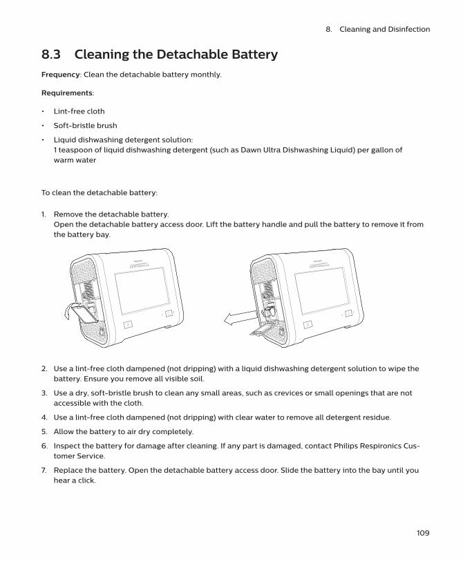
109
8. Cleaning and Disinfection
8.3 Cleaning the Detachable BatteryFrequency: Clean the detachable battery monthly.
Requirements:
• Lint-free cloth
• Soft-bristle brush
• Liquid dishwashing detergent solution: 1 teaspoon of liquid dishwashing detergent (such as Dawn Ultra Dishwashing Liquid) per gallon of warm water
To clean the detachable battery:
1. Remove the detachable battery. Open the detachable battery access door. Lift the battery handle and pull the battery to remove it from the battery bay.
2. Use a lint-free cloth dampened (not dripping) with a liquid dishwashing detergent solution to wipe the battery. Ensure you remove all visible soil.
3. Use a dry, soft-bristle brush to clean any small areas, such as crevices or small openings that are not accessible with the cloth.
4. Use a lint-free cloth dampened (not dripping) with clear water to remove all detergent residue.
5. Allow the battery to air dry completely.
6. Inspect the battery for damage after cleaning. If any part is damaged, contact Philips Respironics Cus-tomer Service.
7. Replace the battery. Open the detachable battery access door. Slide the battery into the bay until you hear a click.

110
Trilogy EV300 Universal Instructions for Use
8.4 Rinsing the Air-Inlet Foam FilterThe air-inlet foam filter is the gray foam located on the back panel. It protects Trilogy EV300 from dirt and dust. This filter is for single patient use. Only use Philips Respironics-supplied filters. Ventilation can continue while you are replacing the filter.
Frequency: In the clinical environment, rinse daily and replace monthly.
Requirements: Replacement filter, water
To rinse the disposable inlet filter:
1. Ensure you have a replacement filter nearby.
2. Pinch the filter and pull it out of the filter cover.
3. Insert the clean replacement filter into the filter cover. Ensure it is positioned securely.
4. Visually inspect the filter you just removed from the device.
5. If it is damaged, discard it according to your local regulations. Other-wise, proceed to the next step.
6. Rinse the dirty filter in clear water. Inspect the filter for cleanliness and repeat previous step until the filter is clean.
7. Allow the filter to air dry completely before reinstalling it.

9.1 Service OverviewRepairs and maintenance must be performed by service personnel only. Unauthorized repairs and adjustments could cause death or injury, invalidate the warranty, or result in costly device damage.
The device should be sent for preventative maintenance every four years. Trilogy EV300’s expected service life is 10 years.
9.2 DisposalDispose according to local regulations. If you need help, contact customer service.
9.3 Daily MaintenanceConduct the following maintenance every day.
• Visually inspect accessories for damage or signs of wear. Discontinue use and replace if damaged.
• When using the FiO2 sensor, to maintain accuracy, calibrate the FiO2 sensor daily. See “FiO2 Sensor Calibration.”
9.4 Replacing the Air-Inlet Foam FilterThe air-inlet foam filter is the gray foam located on the back panel. It protects Trilogy EV300 from dirt and dust. Replace if it becomes damaged.
In the clinical environment, replace monthly and between patients. Only use Philips Respironics-supplied filters. Dispose according to local regulations. Ventilation can continue while you are replacing the filter.
9. Service and Maintenance

112
Trilogy EV300 Instructions for Use
To replace the disposable inlet filter:
1. Be sure you have a replacement filter nearby.
2. Pinch the filter and pull it out of the filter cover.
3. Insert the clean replacement filter into the filter cover. Be sure it is positioned securely.
9.5 Replacing the Particulate FilterThe particulate filter is an optional filter that protects Trilogy EV300 from dirt and dust. Replace the particulate filter monthly and between patients. Ventilation can continue while you replace the filter.
Twist the filter cover counterclockwise a quarter of a turn, and then pull straight out to remove.
Twist the filter counterclockwise a quarter of a turn, and then pull straight out to remove.

113
9. Service and Maintenance
Place a new filter onto the bayonet mount then twist the filter clockwise a quarter of a turn while pressing in to secure.
Replace the filter cover and turn clockwise to secure.
9.6 Preparing the Device for Use by a Different PatientIf you are setting up a prescription for a different patient, before creating a new prescription, tap the New Patient button to reset to the default prescription settings, reset the patient operational hours to zero, and clear all existing patient data, including the following: event and alarm logs, circuit calibration, and historical data. Additionally, tapping New Patient deletes all Bluetooth settings.
Before using Trilogy EV300 with a different patient, perform the following actions. Cleaning and disinfection instructions are in “Cleaning and Disinfection.”
� Replace the circuit, including the bacterial filter.
� Clean and disinfect the exterior surface.
� Clean the detachable battery.
� Replace the air inlet foam filter and particulate filter.
� Clear the old patient data from the system: In the Home window, tap the New Patient button.
� If you used an external storage device that contains patient information, such as a USB flash drive, be sure you delete that data by reformatting the storage device.

10.1 OverviewTo prevent adverse performance, use Trilogy EV300 only with accessories intended for use with this device, including circuits, patient monitors and power accessories. For a list of accessories, see the Trilogy EV300 accessories guide at: www.philips.com/EV300
You must be sure accessories and parts are compatible before you connect a patient to the device.
10.2 Portability and AccessoriesWhen using a roll stand, confirm that the ventilator is adequately secured. See the accessory’s instructions for use.
10.3 Power AccessoriesFor instructions, see “Power Management.”
10.4 Patient Circuits and Circuit AccessoriesFor instructions on attaching circuits to the ventilator, see “Device Setup.” For information about the circuit you are using, see the accessory’s instructions for use. For a list of compatible circuits and circuit accessories, see the Trilogy EV300 accessories guide at: www.philips.com/EV300
10.4.1 Circuit Principles
When adding any components to the breathing system, the flow resistance and dead space of the added components such as humidifiers, speaking valves, Heat Moisture Exchangers (HMEs) and filters should be carefully considered in relation to the potential for adverse effects on the patient’s ventilator management and device alarms. If a bacterial filter is exposed to nebulization or humidification, to prevent increased resistance or blockage, the bacterial filter requires replacement more frequently.
10. Accessories

115
10. Accessories
10.4.2 Circuit Requirements
For safe operation, the ventilator requires a patient circuit and filter(s) that meet the following requirements.
Inspiratory/expiratory resistance: up to 5 cmH2O at:
— 30 L/min for adult (20 to 22 mm) circuit size
— 15 L/min for pediatric (14 to 16 mm) or pediatric/adult (19 mm) circuit size
— 2.5 L/min for infant (9 to 13 mm) circuit size
Compliance: up to 4 ml/cmH2O
10.4.3 Leak Compensation
Passive circuits:
The ventilator provides leak compensation for inhaled and exhaled tidal volume measurements. This includes compensation for intentional leak in the patient circuit and leaks that occur at the patient interface, such as cuff leak or mask leak.
Active flow and dual limb circuits:
The ventilator compensates for leak that occurs between the ventilator and the external flow sensor. Leaks that are downstream of the external flow sensor are not compensated for in measurement of inhaled or exhaled tidal volume. Leaks that are downstream of the external flow sensor are compensated for triggering.
Active PAP circuits:
Leak compensation is not available.
10.4.4 Tracheostomy Adapters and Connectors
For disposable tracheostomy adapters and connectors, inspect for damage or wear. Replace weekly or as needed to prevent accumulation of secretion.
10.4.5 Humidification Accessories
For humidification accessories, see the accessory’s instructions for use.
10.4.6 Exhalation Accessories
For exhalation accessories, see the accessory’s instructions for use.

116
Trilogy EV300 Instructions for Use
10.4.7 Flow Sensors
For flow sensors, see the accessory’s instructions for use.
10.4.8 Circuit Filters
For circuit filters, see the filter’s instructions for use.
10.5 Monitors and Sensors
10.5.1 FiO2 Sensor
To use the FiO2 sensor, follow the instructions provided with the sensor. For instructions on using and calibrating this sensor, see “FiO2 Sensor Calibration.”
10.5.1.1 Intended Use
The Philips Respironics FiO2 Sensor is an oxygen sensor device that is used for measuring the fraction of inspired oxygen (oxygen concentration in a percentage).
For instructions on using and calibrating this sensor, see “FiO2 Sensor Calibration.”
10.5.2 External Pulse Oximeter and Sensors
Attach the external pulse oximeter to either USB port on the ventilator. Attach a sensor to the pulse oximeter. Follow the instructions provided with the sensor.
When you connect the external pulse oximeter, the monitored parameters pane will show the SpO2 and pulse rate values during standby and while delivering therapy.
10.5.3 Capnography
Capnography requires the Mainstream CO2 sensor, a compatible airway adapter, and a USB to CO2 monitor adapter cable. For information, see the instructions that accompany each of these accessories.
To connect the CO2 sensor:
1. Connect the CO2 sensor to the adapter cable.
2. Plug the adapter cable into one of Trilogy EV300’s USB ports.
3. Connect the airway adapter to the sensor. See the sensor instructions.
4. Install the sensor at the proximal end of the circuit. See the sensor instructions.
5. Allow two minutes for the sensor to begin providing data in the Monitored Parameters Pane.

117
10. Accessories
6. Perform an “adapter zero” to establish a baseline CO2 level. See “CO2 Sensor Adapter Zero.” Perform an “adapter zero” if you switch from one type of airway adapter to another or when indicated by the system alarm.
10.6 Filters
10.6.1 Air-Inlet Foam Filter
The air-inlet foam filter protects Trilogy EV300 from dirt and dust. This filter is for single patient use. For instructions on rinsing the filter, see “Cleaning and Disinfection.” For instructions on replacing the filter, see”Service and Maintenance.”
10.6.2 Particulate Filter
The particulate filter is an optional filter that protects Trilogy EV300 from dirt and dust. This filter is for single patient use. For instructions on replacing the filter, see “Service and Maintenance.”
10.7 OxygenTo connect high pressure oxygen, see “High Pressure Oxygen.”
To connect low flow oxygen, see “Low Flow Oxygen.”
10.8 Communications CablesTo connect a communications cable, use either of the USB ports. For more information, see the cable’s instructions for use.

118
Trilogy EV300 Instructions for Use
10.9 Remote Alarm and Nurse CallYou can use a Philips Respironics remote alarm or institutional nurse call system with your device. Use the remote alarm or nurse call connector (RJ9) on the Utility panel to connect a remote alarm or nurse call system. The remote alarm or nurse call system should be visible and audible to the caregiver at all times. See the remote alarm or cable’s instructions for further information. For a list of accessories, see the Trilogy EV300 accessories guide.
If you are using a remote alarm or nurse call system, fully test the system before starting ventilation.
• Verify that you can hear the ventilator’s audible alarms on the remote alarm or nurse call system.
• If using a remote alarm, be sure the remote alarm signals when you disconnect the remote alarm cable from the ventilator or the remote alarm. To use the alarm and for further testing instructions, see the remote alarm’s instructions.
• If using a normally closed nurse call system, be sure the nurse call system signals when you disconnect the nurse call cable from the ventilator or the nurse call system. Philips Respironics strongly recommends that you use a normally closed nurse call system.
Warnings:
• Do not rely solely on the audible indicator provided by a remote alarm or nurse call system as the primary indicator of the operating state of the device or of patient events. Use of a remote alarm or nurse call system should be considered a backup to the ventilator’s primary alarm system. The remote alarm or nurse call system is for use only in a medically supervised environment.
• If you are using a nurse call system, Philips Respironics strongly recommends that you use a normally closed nurse call system. Only a normally closed system will alarm if the nurse call cable becomes disconnected. A normally open system will not alarm.
• Be sure that the nurse call systems used do not exceed 42.4VAC peak or 60VDC under normal operating conditions.
10.10 USB Flash DriveThe USB flash drive (removable storage) included with your device can be used to import and export data. See “Data Transfer.”

11.1 OverviewTrilogy EV300 can operate on AC (wall outlet) or DC (battery) power from several sources. Sources are listed in descending priority below.
1. AC Power, see “AC Power” below.
2. External battery (DC) such as a vehicle battery – requires an external battery cable, see “External Bat-tery” below.
3. Detachable battery (DC), see “Detachable Battery.”
4. Internal battery (DC), see “Internal Battery.”
11.2 AC PowerAC power has the highest priority. When AC power is present, the device uses that power to run the device and to charge the detachable and internal batteries.
To use AC power, follow these steps.
1. Plug the socket end of the AC power cord into the power inlet on the device.
2. Attach the retention clip to the cord and screw the clip into the back panel of the device.
3. Plug the pronged end of the power cord into an electrical outlet that is not controlled by a wall switch.
4. Verify the device is using AC power. You should see the green LED light next to the power button appear. If you do not see this light, contact customer service.
5. Periodically inspect the power cord for damage or signs of wear. Discontinue use and replace if dam-aged.
To remove AC power, disconnect the AC power cord from the electrical outlet.
11.3 External BatteryYou can use an external DC power source, such as a vehicle battery, to power the device. The external battery can charge the internal and detachable batteries. You must use a compatible battery cable to connect the battery to the device. Do not use any other cable or improper operation of the device may occur. For a list of accessories, see the Trilogy EV300 accessories guide at: www.philips.com/EV300
For complete instructions, see the battery cable’s accompanying documents. The external battery will power the device when it is disconnected from AC power.
11. Power Management

120
Trilogy EV300 Instructions for Use
Verify that the external battery is set up correctly. You should see the external battery icon appear in the Battery Power Meter on the Status Bar.
11.4 Detachable BatteryThe detachable battery can power the device when disconnected from AC or external battery power. Use only the Philips Respironics Trilogy EV300-series Detachable Battery Pack.
Battery operating time depends on device usage. The operating time shown on the device is only an estimate of the actual remaining power.
The battery includes an LED charge meter. To view the percentage of charge, remove the battery and press the button on the battery. Green lights appear to indicate how much charge remains in the battery.
To remove the detachable battery: open the detachable battery access door. Lift the battery handle and pull the battery to remove it from the battery bay.
To replace the detachable battery: open the detachable battery access door. Slide the battery into the battery bay until you hear a click.
Verify the detachable battery is installed correctly. You should see the detachable battery icon appear in the Battery Power Meter on the Status Bar.
11.4.1 Warnings
• Do not disassemble or open, drop, crush, bend or deform, puncture, or shred the detachable battery pack.
• If the detachable battery is dropped or mishandled, discontinue use of the battery and contact Philips Respironics Customer Service.
• Do not modify or remanufacture, attempt to insert foreign objects into the battery, immerse or expose the battery to water or other liquids, or expose the battery to fire, excessive heat, or put the battery in a microwave oven.
• Only use the battery for the systems for which it is specified.
• Only use the battery with a charging system specified by the manufacturer/supplier.
• Do not allow metallic or conductive objects to contact battery terminals, which may result in a short-circuit.

121
11. Power Management
• Replace the battery only with another battery specified by the manufacturer. Use of an unqualified battery may present a risk of fire, explosion, leakage, or other hazard.
• Improper battery use may result in a fire, explosion, or other hazard.
11.4.2 Cautions
• Do not expose the battery to temperatures outside of the specifications. This may increase the risk of fire or damage the battery.
• Do not leave the battery in a fully discharged state for an extended time.
• The service life of the detachable battery will decrease depending on the battery age, the number of charge-discharge cycles, and operation or storage at higher temperatures.
• As with most rechargeable lithium-ion batteries, exposing the battery to elevated temperatures for extended times reduces the amount of power that battery can store. For example, a battery may be stored for up to a year at 25° C without experiencing a significant impact to the amount of power that it can store. After being stored for a year at 60° C, that same battery may lose as much as 30% of the power it can store.
11.4.3 Detachable Battery Specifications
Voltage: 14.4 to 14.8 VDC Rated capacity: 80 Wh minimum Chemistry type: Lithium-Ion
Charge operating temperature: 0° C to 45° C
Storage temperature: -20° C to 60° C
Relative humidity (operating and storage): 5 to 93% (non-condensing)
11.5 Internal BatteryInternal battery power is the lowest priority power source.
The internal battery appears in the Battery Power Meter on the Status Bar. For help, see “Battery Status.”

122
Trilogy EV300 Instructions for Use
11.6 Battery StatusThe battery power meter appears in the status bar at the bottom of the window. The meter shows the battery status. The In-use Arrow points to the battery in use (if any).
Battery operating time depends on the characteristics of the battery and usage of the device. The capacity of the battery shown on the Battery Power Meter is only an estimate.
During active therapy, tap the power meter to view more details.
• Estimated battery time remaining (for the internal and detachable batteries)
• Estimated remaining battery power shown as a percent of total capacity (for the external battery)
You can also view battery status in the Monitoring Window: see “Monitoring Window.”
For a list of power icons, see “Power Icons.”
11.7 Power LossSeveral alarms are related to power and power loss. For help on these alarms and test procedures, see “Alarms and System Messages.”
If all power sources are lost during active therapy, as soon as a power source is connected, the device will begin to deliver therapy again. All alarm settings are retained and restored.
Internal Battery
DetachableBattery
ExternalBattery
In-useArrow
Battery Power Meter in the Status Bar

123
11. Power Management
11.8 Power IconsThe following is a list of power icons that appear in the status bar.
Note: The charge icon appears on top of the power icon when the internal or detachable battery is charging.
Estimated capacity
Internal Battery
Detachable Battery
External Battery
81-100% capacity
61-80% capacity
41-60% capacity
21-40% capacity
1-20% capacity
Low power remaining
Nearly depleted
0% capacity or failed

12.1 OverviewYou can connect this device to external systems through USB or wireless connections.
12.2 External SystemsUse either USB port to connect to external systems such as hospital systems.
12.3 WirelessThis device has Bluetooth SmartReady wireless technology, which includes Bluetooth Classic and Bluetooth Low Energy. Bluetooth allows Trilogy EV300 to communicate with a compatible Bluetooth device approved by Philips Respironics. Bluetooth functionality may not be present in all models.
Warning: Other equipment may interfere with this device, even if the other equipment complies with CISPR 8 emission requirements.
Warning: The Health Industry Manufacturers Association recommends that a minimum separation of six inches be maintained between a wireless phone and a pacemaker to avoid potential interference with the pacemaker. The Trilogy EV300 on-board Bluetooth communication should be considered a wireless phone in this regard.
QoS: Wireless Quality of Service (QoS) refers to the necessary level of service and performance needed for the wireless functions of the device. It involves parameters such as reliability of data transmission, effective transfer rate, error rate, and mechanisms to define priority levels for time-critical signals.
Bluetooth QoS: Bluetooth uses frequency hopping, channel coding, and error correction to address interference and is designed to operate with other devices that occupy the same spectrum. In addition to the measures defined in the Bluetooth standard, the Trilogy EV300 radio incorporates other methods to minimize the likelihood of QoS problems. These include:
• Data sent between the ventilator and any external devices uses additional checksum verification to ensure that data is correctly received without errors.
• The ventilator is a portable device and will not always be near the external gateway device when the ventilator is ready to transfer data. The system is designed to take this into account. The system can tolerate latency and will keep retrying if something occurs that prevents successful data transfer. This retry mechanism happens automatically and requires no intervention by the user. The external Bluetooth gateway device attempts to reconnect once per minute until it successfully connects and the data transfer is complete.
12. Connectivity

If the device’s display is erratic, relocate the device to an area away from electronic equipment (such as cellular phones, cordless phones, computers, TVs, electronic games, or hair dryers).
If Bluetooth communication issues are encountered, check to see if other nearby devices are operating in the immediate vicinity at the same 2.4 GHz frequency as the ventilator Bluetooth radio. These devices include:
• Other Bluetooth devices• Wi-Fi devices• Microwave ovens
Portable and mobile RF communications equipment should be used no closer to any part of the device, including cables, than the recommended 30 cm separation distance.
12.4 Connectivity ActionsTo access the Bluetooth window:
1. In the menu bar, tap the Options icon.
2. In the Options window, tap Device Options.
3. In the Device Options window, tap Bluetooth.
To enable Bluetooth connections, In the Bluetooth window, in the Bluetooth section, tap On.
To view connection status, the Bluetooth window contains a connection status indicator, including the MAC address of the current or most recently connected device.
125

13.1 OverviewThis chapter contains technical data and specifications.
13.2 Specifications
13.2.1 Ventilation types and modes• A/C-PC: Assisted control (pressure control)• A/C-VC: Assisted control (volume control)• CPAP: Continuous positive airway pressure• PSV: Pressure support ventilation• S/T: Spontaneous/timed ventilation• SIMV-PC: Synchronized intermittent mandatory ventilation (pressure control) • SIMV-VC: Synchronized intermittent mandatory ventilation (volume control) • AVAPS-AE
13.2.2 Controls
AVAPS with passive circuit PSV, S/T, and A/C-PC modes only
Tidal volume 35 – 2000 ml
Breath rate 0 – 80 BPM
PEEP 0 – 35 cm H2O for active exhaust circuits3 – 25 cm H2O for passive circuits
EPAP/CPAP 3 – 25 cm H2O
IPAP 3 – 60 cm H2O
Pressure support/pressure control 0 – 60 cm H2O, patient pressure limited to 60 cm H2O
Inspiratory time 0.3 – 5.0s, constrained to prohibit an inverse I:E ratio
Rise time 0, 1, 2, 3, 4, 5, 6
Triggering and cycling Off, Auto-Trak, Sensitive Auto-Trak, and Flow Trigger
Flow trigger sensitivity 0.5 – 9 L/min
Flow cycle sensitivity 10% – 90% of peak flow
Flow pattern Square, Ramp
FiO2 21% – 100%
Inspiratory time min/max 0.3 - 3.0 sec
Backup ventilation On - Off
13. Technical Data

127
13. Technical Data
13.2.3 Measured and Displayed Patient Parameters
Tidal volume (Vti or Vte) 0 to 2000 ml in increments of 1 ml
Minute ventilation (MinVent) 0 to 30 L/min in increments of 0.1 L/min
Leak 0 to 200 L/min in increments of 0.1 L/min
Respiratory rate (RR) 0 to 90 BPM in increments of 1 BPM
Peak inspiratory flow (PIF) 0 to 200 L/min in increments of 0.1 L/min
Peak inspiratory pressure (PIP) 0 to 90 cm H2O in increments of 0.1 cm H2O
Mean airway pressure 0 to 90 cm H2O in increments of 0.1 cm H2O
Percentage spontaneous triggered breaths (%Spont Trig)
0 to 100% in increments of 1%
I:E ratio 9.9:1 to 1:9.9
Dynamic compliance (Dyn C) 1 to 100 ml/cm H2O in increments of 1 ml/cm H2O
Dynamic resistance (Dyn R) 5 to 200 cm H2O/l/sec in increments of 1 cm H2O/l/sec
Dynamic plateau pressure (Dyn Pplat)
0 to 90 cm H2O in increments of 1 cm H2O
Auto-PEEP 0 to 20 cm H2O in increments of 1 cm H2O
FiO2 with FiO2 sensor 21% to 100% in increments of 1%
SpO2 with pulse oximeter accessory
0 to 100% in increments of 1%
Pulse rate with pulse oximeter accessory
18 to 321 beats per minute in increments of 1 beat per minuteSee “Pulse Oximeter.”
EtCO2 with CO2 accessory 0 to 150 mmHg in increments of 1 mmHgSee “EtCO2 (with Mainstream CO2 sensor).”
ml/kg Calculated based on the entered patient weight or the calculated IBW and the measured Vti.
13.2.4 Environmental
Operating • Temperature: 0° C to 40° C, 32° F to 104° F• Relative humidity: 5% to 90% RH, non-condensing• Atmospheric pressure: 62 to 106 kPa• Altitude: approximately -384 m to 3954 m (-1,261 to 12,971 ft)• Battery charging temperature: 5° C to 40° C, 32° F to 104° F
Transient operating temperature, excluding high pressure oxygen blending
-20° C to 50° C, -4° F to 122° F
Storage • Temperature: -25° C to 70° C, -13° F to 158° F• Relative humidity: 5% to 93% RH, non-condensing

128
Trilogy EV300 Instructions for Use
13.2.5 Physical
Weight 6.3 Kg (13.8 lbs)
Size • 19.3cm D x 28.6 cm W x 24.5 cm H• 7.6” D x 11.25” W x 9.65” H
Screen dimensions 8”, 20.32 cm
Ingress protection IP22: protection against finger-sized objects and protected against dripping water when tilted up to 15 degrees.
IEC 60601-1 classification Type of protection against electric shock: Class II equipmentDegree of protection against electric shock – type BF applied part
Composition This device does not contain natural latex rubber or dry natural rubber.
Expected service life 10 years
Internal memory capacity 2 Gb
Mode of operation Continuous
Maximum limited pressure 90 cm H2O
Minimum limited pressure Active circuits: 0 cm H2OPassive circuits: 3 cm H2O
Applied parts • Pulse oximeter• Breathing circuit• Components added to the breathing circuit including: flow
sensor, flow sensor cable, and CO2 accessory and cable
13.2.6 Electrical
AC input voltage 100V – 240V, 50/60 Hz, 1.7-0.6 A
DC input voltage 12/24V 6.5A
Internal and detachable Li-ion batteries
15 hours’ nominal total run time per method in IEC 80601-2-72 (7.5 hours each battery)
Charge time for detachable and internal battery:
• From 0% to 80%: 2.5 hours• From 0% to 100%: 3.5 hours
Degree of protection against electric shock
Type BF applied part

129
13. Technical Data
13.2.7 Audio
Alarm sound pressure level 53.9 dBA to 85.5 dBA over the setting range of low, medium, and high
Sound pressure level<=43.7 dBA Ventilator, circuit and exhalation device measured according to ISO 80601-
2-12
Sound power level<=51.6 dBAVentilator, circuit and exhalation device measured according to ISO 80601-
2-12
13.2.8 Oxygen
Low flow 0 to 30 L/min; maximum 10 psi (dry oxygen)
High pressure 280 to 600 kPa (41 to 87 psi) (dry oxygen)
Ventilator response to a 21 -90% increase in oxygen concentration
< 30 seconds
13.2.9 Control Accuracy
Pressure ± (2 cm H2O + 4% of the setting)
Tidal volume ± (4 ml + 15% of setting)
FiO2 ± 5 % FiO2
13.2.10 Monitored Parameter Accuracy
Airway pressure ± (2 cm H2O + 4% of actual)
Tidal volume ± (4 ml + 15% of actual) for volumes ≥ 35 ml± 10 ml for volumes < 35 ml
FiO2 ± (2.5% FiO2 + 2.5% of actual reading) within a 24-hour sensor calibration period, or a change in altitude
Measurement is not automatically compensated for changes in altitude.
Response time: < 11 seconds
EtCO2 See “EtCO2 (with Mainstream CO2 sensor).”
SpO2 and pulse rate See “Pulse Oximeter.”
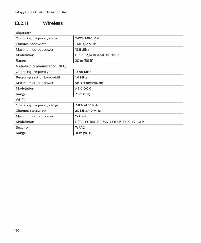
130
Trilogy EV300 Instructions for Use
13.2.11 Wireless
Bluetooth
Operating frequency range 2402-2480 MHz
Channel bandwidth 1 MHz/2 MHz
Maximum output power 15.6 dBm
Modulation GFSK, Pi/4 DQPSK, 8DQPSK
Range 20 m (66 ft)
Near-field communication (NFC)
Operating frequency 13.56 MHz
Receiving section bandwidth 1.4 MHz
Maximum output power 58.3 dBuV/m@3m
Modulation ASK, OOK
Range 2 cm (1 in)
Wi-Fi
Operating frequency range 2412-2472 MHz
Channel bandwidth 20 MHz/40 MHz
Maximum output power 19.6 dBm
Modulation DSSS, OFDM, DBPSK, DQPSK, CCK, 16-QAM
Security WPA2
Range 30m (98 ft)
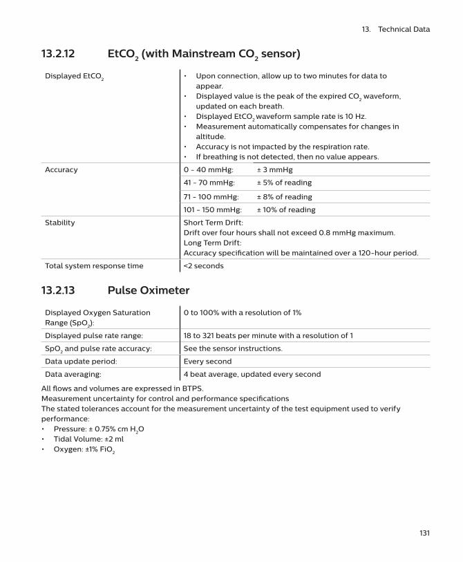
131
13. Technical Data
13.2.12 EtCO2 (with Mainstream CO2 sensor)
Displayed EtCO2 • Upon connection, allow up to two minutes for data to appear.
• Displayed value is the peak of the expired CO2 waveform, updated on each breath.
• Displayed EtCO2 waveform sample rate is 10 Hz.• Measurement automatically compensates for changes in
altitude.• Accuracy is not impacted by the respiration rate.• If breathing is not detected, then no value appears.
Accuracy 0 - 40 mmHg: ± 3 mmHg
41 - 70 mmHg: ± 5% of reading
71 - 100 mmHg: ± 8% of reading
101 - 150 mmHg: ± 10% of reading
Stability Short Term Drift: Drift over four hours shall not exceed 0.8 mmHg maximum.Long Term Drift: Accuracy specification will be maintained over a 120-hour period.
Total system response time <2 seconds
13.2.13 Pulse Oximeter
Displayed Oxygen Saturation Range (SpO2):
0 to 100% with a resolution of 1%
Displayed pulse rate range: 18 to 321 beats per minute with a resolution of 1
SpO2 and pulse rate accuracy: See the sensor instructions.
Data update period: Every second
Data averaging: 4 beat average, updated every second
All flows and volumes are expressed in BTPS.Measurement uncertainty for control and performance specifications The stated tolerances account for the measurement uncertainty of the test equipment used to verify performance: • Pressure: ± 0.75% cm H2O• Tidal Volume: ±2 ml• Oxygen: ±1% FiO2

132
Trilogy EV300 Instructions for Use
13.3 Pneumatic Diagram

14.1 Standards ComplianceThis device conforms to the following standards:
14.1.1 GeneralIEC 60601-1-1 Medical electrical equipment. Part 1-1: General requirements for safety. Collateral standard: Safety requirements for medical electrical systems
14.1.2 Collateral
IEC 60601-1-2 Medical electrical equipment. Part 1-2: General requirements for basic safety and essential performance. Collateral Standard: Electromagnetic disturbances. Requirements and tests
14.1.3 Particular
Device essential performance is specified in each of the following standards:
• ISO 80601-2-12: Medical electrical equipment. Part 2-12: Particular requirements for basic safety and essential performance of critical care ventilators
• ISO 80601-2-55 Medical electrical equipment. Part 2-55: Particular requirements for the basic safety and essential performance of respiratory gas monitors
• ISO 80601-2-61 Medical electrical equipment. Part 2-61: Particular requirements for basic safety and essential performance of pulse oximeter equipment
14.1.4 Wireless communication
• Bluetooth Core Specification version 4.1
• ISO/IEC 18092:2013: Information technology. Telecommunications and information exchange between systems. Near Field Communication. Interface and Protocol (NFCIP-1)
• ISO IEC 21481 ed 2.0: Information technology. Telecommunications and information exchange between systems. Near Field Communication Interface and Protocol -2 (NFCIP-2)
• ISO/IEC 14443 ed 2.0: Identification cards. Contactless integrated circuit cards. Proximity cards.
• WLAN Standard: IEEE 802.11 (2012) b/g/n: Information technology. Telecommunications and information exchange between systems. Local and metropolitan area networks. Specific requirements. Part 11: Wireless LAN Medium Access Control (MAC) and Physical Layer (PHY) Specifications
14. Regulatory Information

134
Trilogy EV300 Instructions for Use
14.2 EMC InformationThis ventilator generates audible and visual alarms to alert you if it is not able to provide ventilation or if external monitoring is lost during an EMC disturbance.
Warnings:
• Avoid using this equipment adjacent to or stacked with other equipment because it could result in improper operation. Although the other equipment may comply with EMC standard requirements, interference can occur. If such use is necessary, observe this equipment and the other equipment to verify that both are operating normally.
• This device shall not be used near active high frequency (HF) surgical equipment, medical devices such as X-ray devices and diathermy, or in an RF shielded room of medical equipment or system for magnetic resonance imaging, where the intensity of electromagnetic (EM) disturbances is high.
• This device shall not be used near RFID or electromagnetic security systems.
• The use of accessories, transducers and/or cables other than those specified, with the exception of those sold by the manufacturer as replacement parts for internal components, may result in increased emissions or decreased immunity of the equipment or system.

135
14. Regulatory Information
14.2.1 Guidance and Manufacturer’s Declaration - Electromagnetic Emissions
This device is intended for use in the electromagnetic environment specified below. The user of this device should make sure it is used in such an environment.
Emissions Test Compliance Electromagnetic Environment - Guidance
RF emissions CISPR 11 Industrial, scientific and medical equipment. Radio-frequency disturbance characteristics. Limits and methods of measurement
Group 1 The device uses RF energy only for its internal function. Therefore, its RF emissions are very low and are not likely to cause any interference in nearby electronic equipment.
RF emissions CISPR 11
Class B The device is suitable for use in all establishments, including domestic establishments and those directly connected to the public low-voltage power supply network.
Harmonic emissions IEC 61000-3-2 Electromagnetic compatibility (EMC). Part 3-2: Limits. Limits for harmonic current emissions (equipment input current smaller than or equal to 16 A per phase)
Class A
Voltage fluctuations/Flicker emissions IEC 61000-3-3 Electromagnetic compatibility (EMC) - Part 3-3: Limits - Limitation of voltage changes, voltage fluctuations and flicker in public low-voltage supply systems, for equipment with rated current ≤ 16 A per phase and not subject to conditional connection
Complies
Emission of Radio Frequency Energy RTCA/DO-160G Section 21
Category M This device is suitable for use on board commercial airplanes inside passenger cabin.

136
Trilogy EV300 Instructions for Use
14.2.2 Guidance and Manufacturer’s Declaration - Electromagnetic Immunity
This device is intended for use in the electromagnetic environment specified below. The user of this device should make sure it is used in such an environment.
Immunity Test IEC 60601 Test Level Compliance Level Electromagnetic Environment - Guidance
IEC 61000-4-2 Electromagnetic compatibility (EMC). Part 4-2: Testing and measurement techniques. Electrostatic discharge immunity test
±8 kV contact
±2 kV, ±4 kV, ±8 kV, and ±15 kV air
±8 kV contact
±2 kV, ±4 kV, ±8 kV, and ±15 kV air
Floors should be wood, concrete, or ceramic tile. If floors are covered with synthetic material, the relative humidity should be at least 35%.
IEC 61000-4-4 Electromagnetic compatibility (EMC). Part 4-4: Testing and measurement techniques. Electrical fast transient/burst immunity test
±2 kV for power supply lines
±1 kV for input-output lines
±2 kV for supply mains
±1 kV for input/output lines
Mains power quality should be that of a typical home or hospital environment.
IEC 61000-4-5 Electromagnetic compatibility (EMC) - Part 4-5 Testing and measurement techniques. Surge immunity test
±1 kV line to ground
±2 kV line to ground
±1 kV line to line
N/A - this Class II device does not connect to earth ground
Mains power quality should be that of a typical home or hospital environment.
IEC 61000-4-11 Electromagnetic compatibility (EMC). Part 4-11: Testing and measurement techniques. Voltage dips, short interruptions and voltage variations immunity tests
0% UT 0.5 cycle at 45 degree increments
0% UT 1 cycle
70% UT 25 cycles (30 cycles if US)
0% UT 5 sec
0% UT 0.5 cycle at 45 degree increments
0% UT 1 cycle
70% UT 25 cycles (30 cycles if US)
0% UT 5 sec
Mains power quality should be that of a typical home or hospital environment. If the user of the device requires continued operation during power mains interruptions, it is recommended that the device be powered from an uninterruptible power supply or a battery.

137
14. Regulatory Information
Immunity Test IEC 60601 Test Level Compliance Level Electromagnetic Environment - Guidance
IEC 61000-4-8 Electromagnetic compatibility (EMC). Part 4-8: Testing and measurement techniques. Power frequency (50/60 Hz) magnetic field immunity test
30 A/m 30 A/m Power frequency magnetic fields should be at levels characteristic of a typical location in a typical hospital or home environment.
NOTE: UT is the AC mains voltage prior to application of the test level.

138
Trilogy EV300 Instructions for Use
14.2.3 Guidance and Manufacturer’s Declaration - Electromagnetic Immunity
This device is intended for use in the electromagnetic environment specified below. The user of this device should make sure it is used in such an environment.
Immunity Test IEC 60601 Test Level Compliance Level Electromagnetic Environment - Guidance
Conducted RF IEC 61000-4-6 Electromagnetic compatibility (EMC). Part 4-6: Testing and measurement techniques. Immunity to conducted disturbances, induced by radio-frequency fields.
3 Vrms 150 kHz to 80 MHz 3 Vrms150 kHz to 80 MHz
Portable and mobile RF communications equipment should be used no closer to any part of the device, including cables, than the recommended 30 cm separation distance.
Interference may occur in the vicinity of equipment marked with the following symbol:
6 Vrms Amateur Radio & ISM Bands between 150 kHz and 80 MHz
Vrms Amateur Radio & ISM Bands between 150 kHz and 80 MHz
Radiated RF
IEC 61000-4-3
Electromagnetic compatibility (EMC) - Part 4-3: Testing and measurement techniques - Radiated, radio-frequency, electromagnetic field immunity test
10 V/m
80 MHz to 2.7 GHz
Telecommunication frequencies as specified in clause 8.10 of IEC 60601-1-2:2014
10 V/m
450, 810, 870, 930, 1720, 1845, 1970, and 2450 MHz at 28 V/m
28 V/m
385 MHz at 27 V/m 27 V/m
710, 745, 780. 5240, 5500, and 5785 MHz at 9 V/m
9 V/m

139
14. Regulatory Information
14.3 WirelessNotices: The Bluetooth® word mark and logos are registered trademarks owned by Bluetooth SIG, Inc. and any use of such marks by Philips Respironics is under license. Other trademarks and trade names are those of their respective owners.
The Trilogy EV300-series device transmits data between the therapy device and a mobile device, but it does not store any of your personally-identifiable health information. This connection between the therapy device and a mobile device is encrypted.
This device contains a certified Bluetooth/Wi-Fi radio:
• FCC ID (USA): 2AN9Z-1127941BT
• IC ID (Canada): 3234B-1127941BT
Near field communication (NFC) is certified under the following IDs:
• FCC ID (USA): 2AN9Z-1127941
• IC ID (Canada): 3234B-1127941
Use of non-original manufacturer-approved accessories may violate your local RF exposure guidelines and should be avoided.
This device complies with part 15 of the FCC Rules. Operation is subject to the following two conditions: (1) This device may not cause harmful interference, and (2) this device must accept any interference received, including interference that may cause undesired operation. This equipment has been tested and found to comply with the limits for a Class B digital device, pursuant to Part 15 of the FCC Rules. These limits are designed to provide reasonable protection against harmful interference in a residential installation. This equipment generates, uses, and can radiate radio frequency energy and, if not installed and used in accordance with the instructions, may cause harmful interference to radio communications. However, there is no guarantee that interference will not occur in a particular installation. If this equipment does cause harmful interference to radio, TV reception, or other devices which can be determined by turning the equipment on and off, the user is encouraged to try to correct the interference by one or more of the following measures:
• Reorient or relocate the receiving antenna (on the radio, TV, or other device).
• Increase the separation between the equipment and receiver.
• Connect the equipment into an outlet on a circuit different from that to which the receiver is connected.
• Consult the dealer of the device for help.

140
Trilogy EV300 Instructions for Use
14.3.1 ISED License Exemption
This device contains license-exempt transmitter(s)/receiver(s) that comply with Innovation, Science and Economic Development Canada’s license-exempt RSS(s). Operation is subject to the following two conditions:
1. This device may not cause interference.
2. This device must accept any interference, including interference that may cause undesired operation of the device.
14.4 Software LicensingThis product contains software licensed under an open source license. For acknowledgements and license texts, a list can be viewed on the User Interface under Options > Information > Software Licenses. Philips Respironics hereby offers to deliver, upon request, a copy of the complete corresponding source code for the copyrighted open source software packages used in this product for which such delivery is requested by the respective licenses. This offer is valid for as long as the respective licenses require this offer to be valid. To obtain source code, please send your request in English with product type to [email protected]. If you prefer not to use email or if you do not receive confirmation receipt within 2 weeks after mailing to this email address, please write in English to “Open Source Team, Philips Intellectual Property & Standards, High Tech Campus 5, 5656 AE Eindhoven, The Netherlands”. If you do not receive timely confirmation of your letter, please send an email to the email address above..

15.1 Glossary of TermsThe following terms and acronyms appear throughout this manual.
Term Definition
A/C-PC Therapy mode: Assist control – assist-control and mandatory breaths with pressure control and optional AVAPS
A/C-VC Therapy mode: Assist control – assist control and mandatory breaths with volume control
Active Circuit Circuit that includes an active exhalation device
Apnea Interval Interval in which the ventilator detects patient-triggered breaths.
Assist-Control Breath Patient-initiated, time-cycled breath
AVAPS-AE Mode Therapy mode: Provides variable pressure to achieve a target volume and to reduce airway resistance. Breaths are spontaneous, assist-control, mandatory or auto backup
Auto PEEP Estimate of the any pressure (above PEEP) that exists in the patient airway at the end of exhalation
It is updated at the end of exhalation of every mandatory or assisted (timed-cycled) breath.
This value appears in the displayed parameters pane when the therapy mode is A/C-PC, A/C-VC, SIMV-PC, or SIMV-VC and the circuit type is passive, active flow, or dual limb.
Average Total Leak (Leak) The average flow from the ventilator that did not reach the patient during the previous breath.
This value appears in the displayed parameters pane when the circuit type is passive.
Blower Hours The total number of hours that the blower has been on over the life of the device. This value helps determine when the ventilator needs to be serviced. You cannot reset this value. It can only be reset by a service center.
BPM Breaths per minute or beats per minute
BTPS Body temperature and pressure saturated; A standardization for lung volumes and flows to barometric pressure at sea level, body temperature, and saturated with water vapor reflecting the condition of air in the lung.
CPAP Therapy mode: Continuous positive airway pressure
15. Glossary

142
Trilogy EV300 Instructions for Use
Term Definition
Dyn C Estimate of the compliance of the pulmonary system (lung and chest wall) in milliliters per cmH2O, computed on a breath-to-breath basis without requiring a static maneuver.
It is updated at the end of exhalation of every mandatory or assisted breath (time cycled), and is displayed as the average over the last three mandatory or assisted breaths. It is corrected to body temperature and pressure saturated (BTPS) conditions.
This value appears in the displayed parameters pane when the therapy mode is A/C-PC, A/C-VC, SIMV-PC, or SIMV-VC and the circuit type is passive, active flow, or dual limb.
Dyn R Estimate of the airway resistance in cmH20/(L/s), computed on a breath-to-breath basis without requiring a static maneuver.
It is updated at the end of exhalation of every mandatory or assisted (timed cycled) breath, and is displayed as the average over the last three mandatory or assisted breaths. It is corrected to body temperature and pressure saturated (BTPS) conditions.
This value appears in the displayed parameters pane when the therapy mode is A/C-PC, A/C-VC, SIMV-PC, or SIMV-VC and the circuit type is passive, active flow, or dual limb.
Dyn Pplat Estimate of the maximum alveolar pressure during inspiration in cmH20, computed on a breath-to-breath basis without requiring a static maneuver. It is compensated for Auto-PEEP.
It is updated at the end of exhalation of every mandatory or assisted (timed cycled) breath.
This value appears in the displayed parameters pane when the therapy mode is A/C-PC, A/C-VC, SIMV-PC, or SIMV-VC and the circuit type is passive, active flow, or dual limb.
EPAP Expiratory positive airway pressure
ESD Electrostatic discharge

143
15. Glossary
Term Definition
EtCO2 End tidal carbon dioxide. The amount of carbon dioxide at the end of exhalation.
No value appears in the displayed parameters pane when the CO2 sensor does not detect a breath.
Upon initially connecting a sensor, allow up to 2 minutes for data to appear.
Respiration rate accuracy (as measured by the CO2 sensor) was verified by using a solenoid test setup to deliver a square wave of known CO2 concentration to the device. 5% and 10% CO2 concentrations were used and respiration rate was varied over the range of the device. Pass/fail criteria was a comparison of the respiratory rate output from the sensor to the frequency of the square wave. EtCO2 measurements at those rates were compared to the CO2 readings under static flow conditions.
Exhaled tidal volume Vte
The exhaled tidal volume in milliliters, derived from summing the expiratory patient flow. The Vte is updated once per breath. It is corrected to body temperature and pressure saturated (BTPS) conditions.
This value appears in the displayed parameters pane when the circuit type is passive, active flow, or dual limb.
FiO2 Fraction of inspired oxygen (the percentage of oxygen in the air inhaled) It is updated approximately every 300msec. The FiO2 measurement does not automatically compensate for changes in altitude.
I:E Ratio The ratio of inspiratory time to expiratory time on the previous breath expressed as 1:X or X:1 for inverse ratios.
IBW Estimated ideal body weight
Infant Full term newborn up to one month in age with mass that is greater than or equal to 2.5 kg.
Inhaled tidal volume Vti
The tidal volume, in milliliters, delivered to the patient. This value is derived from summing the inspiratory patient flow. The Vti is updated once per breath. It is corrected to body temperature and pressure saturated (BTPS) conditions.
This value appears in the displayed parameters pane when the circuit type is active PAP.
Inspiratory time Length of the inspiratory phase
IPAP Inspiratory positive airway pressure
L/min Liters per minute
Leak See Average Total Leak.
LED Light emitting diode
Mandatory Breath A ventilator-initiated, time-cycled breath

144
Trilogy EV300 Instructions for Use
Term Definition
Manometer Pressure indicator
Mean Airway Pressure (MAP)
The average applied pressure during the breath in cmH2O, displayed as an average over the previous six breaths. It is updated at the end of each exhalation.
Minute Ventilation (MinVent)
The volume of patient exhaled gas in one minute, based on a six-breath average of exhaled tidal volume (Vte) and respiratory rate (BPM). It is corrected to body temperature and pressure saturated (BTPS) conditions. Minute ventilation is updated at the start of each breath, or after 15 seconds if no breath is detected.
For active PAP circuits, the displayed minute ventilation is calculated using the inhaled tidal volume (Vti).
mL/kg Ratio of Vti of the previous breath to the patient weight, corrected to body temperature and pressure saturated (BTPS) conditions. The weight is entered when the patient type is infant, otherwise the IBW is calculated based on the patient height.
Passive Circuit A circuit that includes a passive exhalation device.
Peak Inspiratory Flow (PIF)
The maximum inspiratory flow delivered to the patient in L/min. It is corrected to body temperature and pressure saturated (BTPS) conditions and updated once per breath.
Peak Inspiratory Pressure (PIP)
The maximum inspiratory pressure delivered to the patient in cmH2O, updated once per breath.
PEEP Positive end expiratory pressure.
Percentage Spontaneous Triggered Breaths (%Spont Trig)
The percentage of breaths that are patient-initiated over the most recent 50 breaths. It is updated once per breath.
Pressure Control (PC) Pressure applied during inspiration above PEEP for time-cycled breaths
Pressure Support (PS) Pressure applied during inspiration above PEEP for patient-cycled breaths
PS Pressure support
PSV Therapy mode: Pressure support ventilation with optional AVAPS
Pulse Rate (PR) Number of heartbeats per minute (BPM) measured by pulse oximetry
Ramp Flow pattern in volume control modes where the airflow starts high and decreases throughout inspiration of the breath. See Square.
Respiratory Rate (RR) The measured breathing rate of the patient/ventilator in breaths per minute (BPM), based on a six-breath average that includes both patient-triggered and ventilator-triggered breaths.
It is updated at the start of every breath, after 15sec, or when the low respiratory rate alarm is annunciated, whichever interval is shorter.

145
15. Glossary
Term Definition
Rise Time Time required for the ventilator to change from the expiratory pressure setting to the inspiratory pressure setting when the breath is triggered.
S/T Therapy mode: Spontaneous/timed ventilation – spontaneous breaths with pressure support, mandatory breaths with pressure control, and optional AVAPS
Sigh Delivers a periodic, larger volume breath. Settings adjust the frequency and volume. Available only in A/C-VC mode.
SIMV-PC Therapy mode: Synchronized intermittent mandatory ventilation (pressure control) – spontaneous breaths with pressure support, assist—control breaths and mandatory breaths with pressure control
SIMV-VC Therapy mode: Synchronized intermittent mandatory ventilation (volume control) – spontaneous breaths with pressure support, assist—control breaths and mandatory breaths with volume control
SpO2 Blood oxygen saturation measured by pulse oximetry
Spontaneous Breath Patient-initiated, patient-cycled breath
Square Flow pattern in volume control modes where the airflow is generally constant throughout inspiration of the breath. See Ramp.
Tidal Volume The volume of air passing in and out of the lungs during a breath.
Vte See exhaled tidal volume.
Vti See inhaled tidal volume.

WarrantyWARRANTY
Respironics, Inc. (Philips Respironics) warrants that defects in the Product due to faulty materials and workmanship will be repaired
or replaced at Respironics’ expense if convincing proof of purchase within the Warranty Period (as defined herein) is provided.
Philips Respironics warrants that the Product will be free from defects in material and workmanship under normal and proper
use in accordance with applicable instructions for a period of two years (“Warranty Period”) from the date of shipment by Philips
Respironics to the original purchaser. Accessories and replacement parts are not covered under this warranty. However, Philips
Respironics warrants that the internal battery in the Product will be free from defects in material and workmanship, under normal
and proper use and when correctly maintained, for a period of ninety days from the date of shipment by Philips Respironics to the
original purchaser.
Contact our Consumer Care Center at 1-800-682-7664 (North America), outside North America contact your local Respironics,
Inc. Consumer Care Center. Internet information: www.philips.com/healthcare (North America) or www.philips.com (outside North
America).
LIMITATIONS
If any Product purchased from Philips Respironics fails to conform to the warranties set forth herein during the Warranty Period as
determined by Philips Respironics, in its sole discretion, Philips Respironics may discharge its warranty obligation by choosing to
repair or replace the Product. This may be accomplished by installing new or remanufactured assemblies or components, or by other
repairs deemed appropriate in the sole discretion of Philips Respironics. The choice of repair or replacement by Philips Respironics
will be the sole and exclusive remedy of the original purchaser. Philips Respironics reserves the right, in its sole discretion, to refund
the purchase price in lieu of repair or replacement of the Product. In no event will Philips Respironics’ maximum liability under these
warranties exceed the price paid to Philips Respironics by the original purchaser for the Product.
CONDITIONS
This warranty does not cover damage or injury whether to the Product or to personal property or persons caused by accident,
misuse, abuse, negligence, failure to install in accordance with Philips Respironics’ installation instructions, failure to operate
under conditions of normal use and in accordance with the terms of the operating manual and instructions, failure to maintain in
accordance with the applicable service manuals, or alteration or any defects not related to materials or workmanship of the Product.
This warranty does not cover damage which may occur in shipment and does not apply to the device if dropped, misused, altered or
otherwise damaged after shipment. This warranty does not apply to any Product or individual part of a Product that may have been
repaired or altered by anyone other than Philips Respironics or an authorized Philips Respironics service center. This warranty does
not apply to any Product which is not purchased new.
DISCLAIMERS
EXCEPT AS SET FORTH IN THIS LIMITED WARRANTY, PHILIPS RESPIRONICS MAKES NO WARRANTIES, EXPRESSED OR
IMPLIED, STATUTORY OR OTHERWISE, REGARDING THE PRODUCT, ITS QUALITY OR PERFORMANCE. PHILIPS RESPIRONICS
SPECIFICALLY DISCLAIMS THE IMPLIED WARRANTY OF MERCHANTABILITY AND THE IMPLIED WARRANTY OF FITNESS FOR A
PARTICULAR PURPOSE. IN NO EVENT WILL PHILIPS RESPIRONICS BE LIABLE FOR THE COST OF PROCUREMENT OF SUBSTITUTE
PRODUCTS OR FOR ANY INDIRECT, SPECIAL, CONSEQUENTIAL, PUNITIVE, EXEMPLARY OR INCIDENTAL DAMAGES (INCLUDING,
BUT NOT LIMITED TO, COMMERCIAL LOSS OR LOST REVENUES), FOR ANY CAUSE OF ACTION, WHETHER IN CONTRACT OR
TORT, AND WHETHER OR NOT PHILIPS RESPIRONICS WAS AWARE OR SHOULD HAVE BEEN AWARE OF THE POSSIBILITY OF
THESE DAMAGES. EXCEPT FOR THE OBLIGATIONS UNDER THIS LIMITED WARRANTY, PHILIPS RESPIRONICS WILL NOT HAVE
ANY OBLIGATION OR LIABILITY FOR ANY OTHER LOSS, DAMAGE OR INJURY RESULTING DIRECTLY OR INDIRECTLY FROM THE
PRODUCT. PURCHASER’S SOLE AND EXCLUSIVE REMEDY FOR BREACH OF THE WARRANTIES SET FORTH IN THIS DOCUMENT
WILL BE AS PROVIDED IN THE PARAGRAPH DESCRIBING LIMITATIONS.
Purchaser is cautioned that no person or entity is authorized to make any warranties on behalf of Philips Respironics and any such
alleged warranties are hereby disclaimed by Philips Respironics.


