Environmental Protection Agency United States Response Protocol Toolbox: Planning for and Responding to Drinking Water Contamination Threats and Incidents Interim Final - April 2004 Module 6: Remediation and Recovery Guide
Transcript
Environmental ProtectionAgency
United States
Response Protocol Toolbox:Planning for and Responding to Drinking Water Contamination Threats and Incidents
Interim Final - April 2004
Module 6: Remediation and Recovery Guide
Response Protocol Toolbox: Planning for and Responding to
Drinking Water Contamination Threats and Incidents
Module 6: Remediation and Recovery Guide
Interim Final – April 2004
Is Threat
Is Threat Credible?
Is Incident
Sampling
Initial Threat Evaluation
TH
RE
AT
EV
ALU
AT
ION
P
RO
CE
SS
Possible?
Threat Warning
PLANNING AND PREPARATION
Confirmed?
Site Characterization and
Immediate Operational Response Actions
Public Health Response Actions
Sample Analysis
Remediation and Recovery
EX
PA
ND
ED
R
ES
PO
NS
E A
CT
ION
S
MODULE 6: Remediation and Recovery Guide
OTHER RESPONSE PROTOCOL TOOLBOX MODULES
Module 1: Water Utility Planning Guide (December 2003) Module 1 provides a brief discussion of the nature of the contamination threat to the public water supply. The module also describes the planning activities that a utility may undertake to prepare for responding to contamination threats and incidents.
Module 2: Contamination Threat Management Guide (December 2003) Module 2 presents the overarching framework for management of contamination threats to the drinking water supply. The threat management process involves two parallel and interrelated activities: 1) evaluating the threat, and 2) making decisions regarding appropriate actions to take in response to the threat.
Module 3: Site Characterization and Sampling Guide (December 2003) Module 3 describes the site characterization process in which information is gathered from the site of a suspected contamination incident at a drinking water system. Site characterization activities include the site investigation, field safety screening, rapid field testing of the water, and sample collection.
Module 4: Analytical Guide (December 2003) Module 4 presents an approach to the analysis of samples collected from the site of a suspected contamination incident. The purpose of the Analytical Guide is not to provide a detailed protocol. Rather, it describes a framework for developing an approach for the analysis of water samples that may contain an unknown contaminant. The framework is flexible and will allow the approach to be crafted based on the requirements of the specific situation. The framework is also designed to promote the effective and defensible performance of laboratory analysis.
Module 5: Public Health Response Guide (April 2004) Module 5 deals with the public health response measures that would potentially be used to minimize public exposure to potentially contaminated water. It discusses the important issue of who is responsible for making the decision to initiate public health response actions, and considers the role of the water utility in this decision process. Specifically, it examines the role of the utility during a public health response action, as well as the interaction among the utility, the drinking water primacy agency, the public health community, and other parties with a public health mission.
Module 6: Remediation and Recovery Guide (April 2004) Module 6 describes the planning and implementation of remediation and recovery activities that would be necessary following a confirmed contamination incident. The remediation process involves: system characterization; selection of remedy options; provision of an alternate drinking water supply during remediation; and monitoring to demonstrate that the system has been remediated. Module 6 describes the types of organizations that would likely be involved in this stage of a response, and the utility’s role during remediation and recovery.
2 Interim Final – April 2004
MODULE 6: Remediation and Recovery Guide
ACKNOWLEDGEMENTS
This document was prepared by the United States Environmental Protection Agency, Office of Ground Water and Drinking Water, Water Security Division through a contract with SAIC. The EPA Work Assignment Manager was Brain Frazer, and the SAIC Work Assignment Manager was Mary Wolfe. The primary contributors to the document included:
• Steven C. Allgeier (US EPA, OGWDW) • Patrick E. Ransom (SAIC) • Robert B. Stewart (SAIC)
Other contributors included Susan Dolgin, Grace Robiou, and Veronika Pesinova of the US EPA, OGWDW.
Additional support for this work was provided by a panel of peer reviewers, including: Erica Brown (AMWA), Cliff Bowen (California DHS), Keith Burkhart (ATSDR), Stephen Clark (US EPA, OGWDW), Kim Fox (US EPA, ORD), Alan Hais (US EPA, ORD), David Hartman (Cincinnati Water Works), Ron Hunsinger (EBMUD), Eileen Leininger (Newport News Water Works), Carrie Lewis (Milwaukee Water Works), Matthew Magnuson (US EPA, ORD), Nelson Mix (US EPA OSWER), Debbie Newberry (US EPA, OGWDW), Amit Pramanik (WERF), Alan Roberson (AWWA), Stanley States (Pittsburgh Water and Sewer Authority), Gene Taylor (US EPA, Region 10), Caroline Wehling (US EPA, OGC), Gregory Welter (O’Brien & Gere Engineers), James Wheeler (US EPA, OWM), and Kelvin Yamada (California DHS).
3 Interim Final – April 2004
MODULE 6: Remediation and Recovery Guide
TABLE OF CONTENTS
1 INTRODUCTION AND OVERVIEW......................................................................................................17
1.1 OBJECTIVES..........................................................................................................................................171.2 PROCESS OVERVIEW..........................................................................................................................171.3 ORGANIZATION...................................................................................................................................21
2.1 ELEMENTS OF PLANNING .................................................................................................................232.2 ROLES AND RESPONSIBILITIES .......................................................................................................272.3 DOCUMENTATION ..............................................................................................................................303.1 RISK ASSESSMENT..............................................................................................................................33
3.1.1 RAPID RISK ASSESSMENT ...........................................................................................................343.1.2 INTEGRATING THE SYSTEM CHARACTERIZATION/FEASIBILITY STUDY WITH RISK
3.2 SYSTEM CHARACTERIZATION ........................................................................................................353.2.2 IMPLEMENTING SYSTEM CHARACTERIZATION ...................................................................40
3.3 FEASIBILITY STUDY...........................................................................................................................423.3.1 ESTABLISHING REMEDIAL ACTION OBJECTIVES .................................................................423.3.2 DEVELOPMENT AND SCREENING OF REMEDIAL ALTERNATIVES...................................433.3.3 TREATABILITY STUDIES .............................................................................................................443.3.4 SYSTEM CHARACTERIZATION/FEASIBILITY STUDY (SC/FS) REPORT .............................45
4 ANALYSIS OF ALTERNATIVES AND REMEDY SELECTION .......................................................46
4.1 ANALYSIS OF ALTERNATIVES.........................................................................................................464.1.1 NO ADDITIONAL ACTION ALTERNATIVE ...............................................................................474.1.2 ALTERNATIVES FOR THE TREATMENT OF CONTAMINATED WATER .............................474.1.3 ALTERNATIVES FOR THE REHABILITATION OF SYSTEM COMPONENTS .......................604.1.4 ALTERNATIVES FOR AFFECTED ENVIRONMENTAL MEDIA ..............................................634.1.5 ADDITIONAL RESOURCES...........................................................................................................63
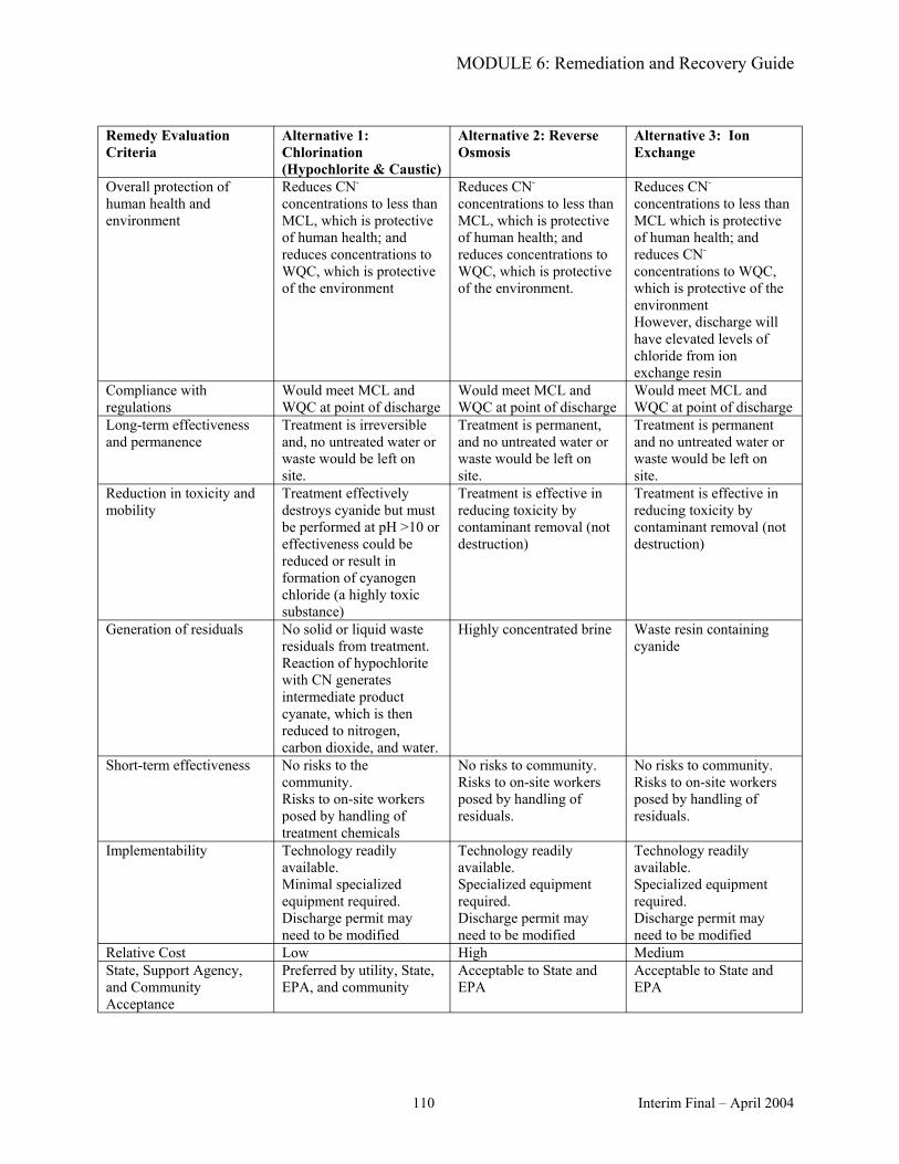
4.2 REMEDY EVALUATION CRITERIA ..................................................................................................644.3 COMPARATIVE ANALYSIS OF ALTERNATIVES AND REMEDY SELECTION .........................65
5 REMEDIAL DESIGN, REMEDIAL ACTION, AND POST-REMEDIATION MONITORING ANDOPERATIONS ............................................................................................................................................67
5.3.1 APPLICABLE REGULATIONS ......................................................................................................695.3.2 TYPES OF WASTE AND MANAGEMENT OPTIONS .................................................................72
5.4 POST-REMEDIATION MONITORING................................................................................................765.5 RETURN TO NORMAL OPERATIONS ...............................................................................................76
6 LONG-TERM ALTERNATE DOMESTIC WATER SUPPLY .............................................................78
6.1 DETERMINING SUPPLY NEEDED TO MEET SYSTEM DEMANDS .............................................796.1.1 ESTIMATING NORMAL DEMAND ..............................................................................................806.1.2 RESTRICTING DEMAND THROUGH CONSERVATION...........................................................81
6.2 IDENTIFYING LONG-TERM ALTERNATE WATER SUPPLIES .....................................................81
4 Interim Final – April 2004
MODULE 6: Remediation and Recovery Guide
6.2.1 OPTIONS FOR ALTERNATE WATER SUPPLIES .......................................................................826.2.2 WHO PROVIDES THE ALTERNATE WATER SUPPLY?............................................................826.2.3 SELECTION OF ALTERNATE WATER SUPPLIES .....................................................................826.2.4 PUBLIC AWARENESS....................................................................................................................83
6.3 IMPLEMENTATION OF LONG-TERM WATER SUPPLY ................................................................846.3.1 CONNECTION TO EXISTING MUNICIPAL OR PRIVATE SUPPLIES......................................846.3.2 CONNECTION TO NEW WATER SOURCE .................................................................................846.3.3 TEMPORARY TREATMENT AND DISTRIBUTION SYSTEMS.................................................85
7 PUBLIC COMMUNICATION ..................................................................................................................86
7.1 AGENCIES INVOLVED IN COMMUNICATION ...............................................................................867.1.1 DEPARTMENT OF HOMELAND SECURITY ..............................................................................867.1.2 WATER UTILITY AND/OR DRINKING WATER PRIMACY AGENCY ....................................87
7.2 FORMS OF COMMUNICATION..........................................................................................................877.2.1 PUBLIC MEETINGS ........................................................................................................................887.2.2 PUBLIC PRESENTATIONS ............................................................................................................897.2.3 PUBLIC WORKSHOPS....................................................................................................................897.2.4 PUBLIC INFORMATION REPOSITORY.......................................................................................907.2.5 REVISED PUBLIC NOTIFICATIONS ............................................................................................90
7.3 TYPES OF INFORMATION TO BE COMMUNICATED....................................................................917.3.1 ALTERNATE WATER SUPPLIES ..................................................................................................917.3.2 REMEDIATION AND RECOVERY ACTIVITIES.........................................................................917.3.3 WATER SYSTEM RETURN TO NORMAL OPERATIONS .........................................................927.3.4 CONTINUED SAMPLING AND ANALYSIS.................................................................................92
8 REFERENCES AND RESOURCES .........................................................................................................93
9.1 SUGGESTED FORMAT FOR SYSTEM CHARACTERIZATION/FEASIBILITY STUDY WORKPLAN.......................................................................................................................................................99
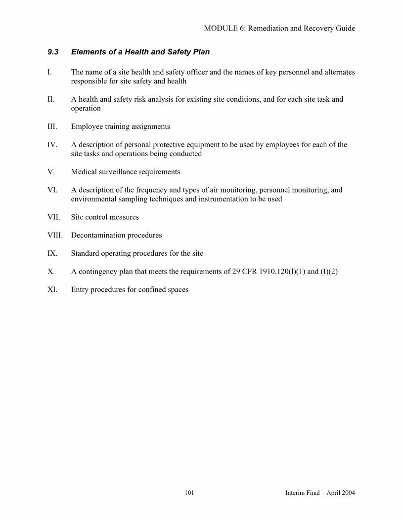
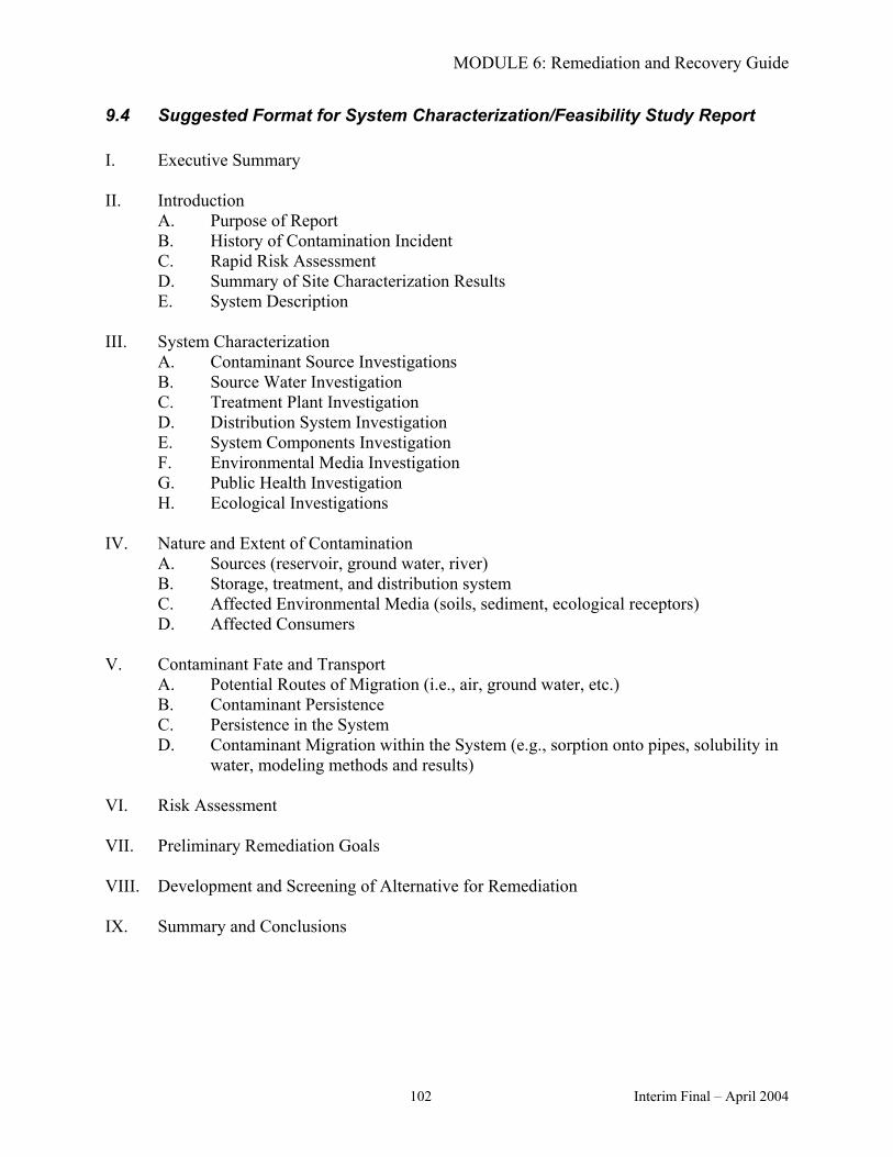
9.2 ELEMENTS FOR A QUALITY ASSURANCE PROJECT PLAN .....................................................1009.3 ELEMENTS OF A HEALTH AND SAFETY PLAN...........................................................................1019.4 SUGGESTED FORMAT FOR SYSTEM CHARACTERIZATION/FEASIBILITY STUDY REPORT
...............................................................................................................................................................1029.5 HYPOTHETICAL EXAMPLE OF A CONTAMINATION THREAT TO A DRINKING WATER
SYSTEM: THREAT WARNING THROUGH REMEDIATION AND RECOVERY ........................103
LIST OF TABLES
TABLE 6-1. DOCUMENTATION OF PLANNING, IMPLEMENTATION, AND ASSESSMENT ACTIVITIES FOR WATER SYSTEM REMEDIATION AND RECOVERY .......................................................................31
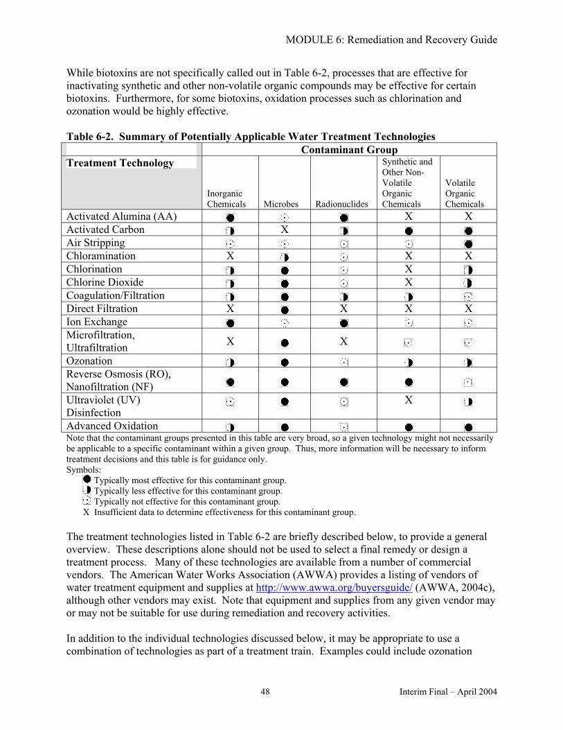
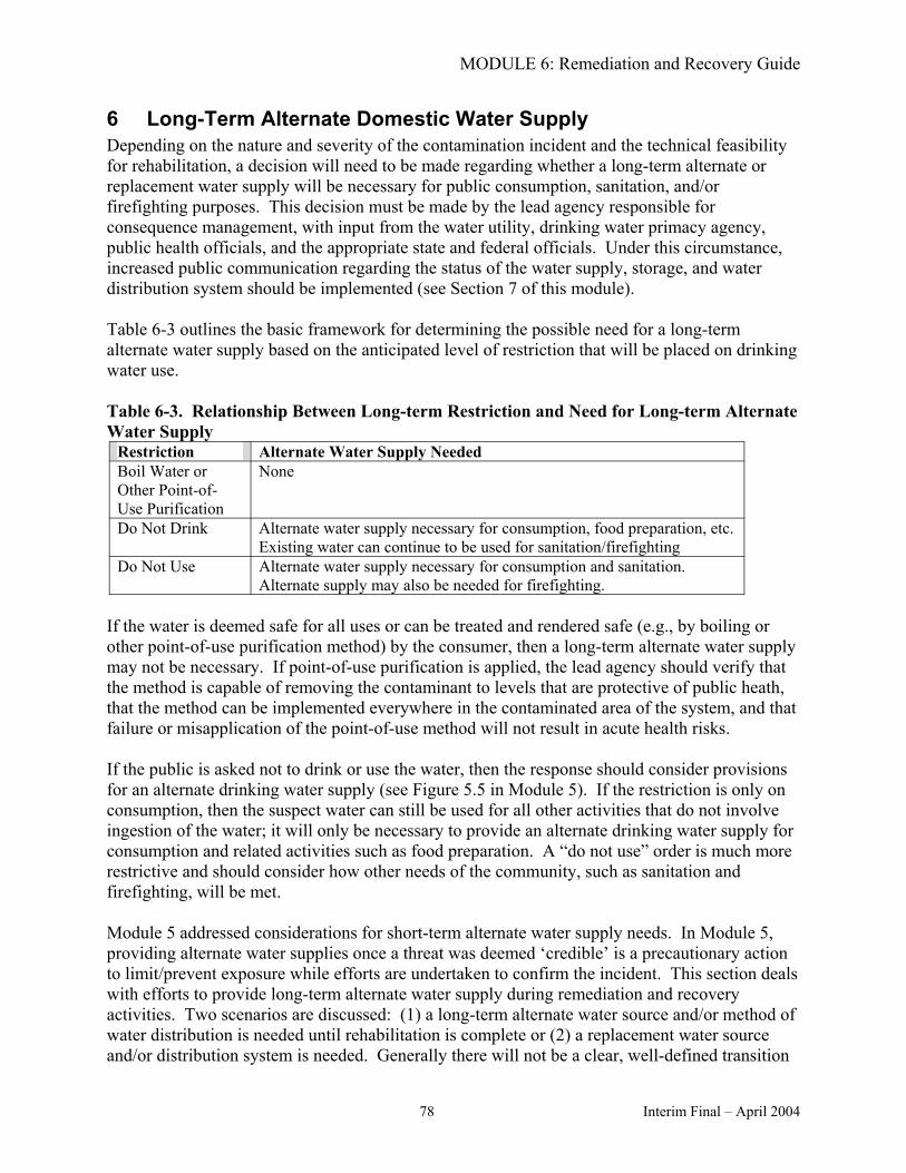
TABLE 6-2. SUMMARY OF POTENTIALLY APPLICABLE WATER TREATMENT TECHNOLOGIES TABLE 6-3. RELATIONSHIP BETWEEN LONG-TERM RESTRICTION AND NEED FOR LONG-TERM
........48
ALTERNATE WATER SUPPLY .....................................................................................................................78
5 Interim Final – April 2004
MODULE 6: Remediation and Recovery Guide
LIST OF FIGURES
FIGURE 6-1. OVERVIEW OF THE REMEDIATION AND RECOVERY PROCESS...........................................20 FIGURE 6-2. INCIDENT COMMAND STRUCTURE FOR REMEDIATION AND RECOVERY ACTIVITIES 27 FIGURE 6-3. PROCESS FOR EVALUATING THE NEED FOR A TREATABILITY STUDY ............................45 FIGURE 6-4. CONCEPTUAL FRAMEWORK FOR IMPLEMENTING A LONG-TERM ALTERNATE WATER
The mention of trade names or commercial products does not constitute endorsement or recommendation for use.
NOTE REGARDING CONSISTENCY WITH OTHER RESPONSE PLANNING EFFORTS
This module includes references to the Federal Response Plan (FRP) and the United States Government Interagency Domestic Terrorism Concept of Operations Plan (CONPLAN). At this time, the Department of Homeland Security is developing a National Response Plan (NRP), which will supercede the FRP and CONPLAN (US Department of Homeland Security, 2004). The final NRP is scheduled to be published in July 2004. After publication of the final NRP, EPA plans to update this module and other modules of the Response Protocol Toolbox to be consistent with the NRP.
NOTE REGARDING REGULATORY AND STATUTORY CITATIONS
This module summarizes and contains references to specific sections of the Code of Federal Regulations (CFR) and to specific Statutes that codify the Nation’s environmental laws (e.g., the Clean Water Act). The summaries contained herein do not substitute for these requirements. Interested persons should become familiar with the regulations and Statutes themselves. CFR sections can be accessed at http://www.gpoaccess.gov/ecfr/. Additional information on specific environmental laws, along with links to the full statutory text, can be found at http://www.epa.gov/epahome/laws.htm. The full text of the Public Health Security and Bioterrorism Preparedness and Response Act of 2002 (PL 107-188, June 12, 2002), or Bioterrorism Act, may be found at http://frwebgate.access.gpo.gov/cgi-bin/getdoc.cgi?dbname=107_cong_public_laws&docid=f:publ188.107.pdf.
AA Activated alumina AMSA Association of Metropolitan Sewerage Agencies ATSDR Agency for Toxic Substances and Disease Registry AWWA American Water Works Association CDC Centers for Disease Control and Prevention CERCLA Comprehensive Environmental Response, Compensation, and Liability Act CFR CWA CSM DHS DOJ EPCRA ERP ESF FBI FEMA FRP FSP GAC GIS HASP HHS HSPD ICS JIC LDR MCL NCP NF NPDES O&M OSHA PAC PDD POTW PRG
Code of Federal Regulations Clean Water Act Conceptual site model Department of Homeland Security Department of Justice Emergency Planning Community Right-to-Know Act Emergency response plan Emergency support function Federal Bureau of Investigation Federal Emergency Management Agency Federal Response Plan Field sampling plan Granular activated carbon Geographic information system Health and safety plan Department of Health and Human Services Homeland Security Presidential Directive Incident Command System Joint Information Center Land Disposal Restrictions Maximum contaminant level National Oil and Hazardous Substances Pollution Contingency Plan Nanofiltration National Pollutant Discharge Elimination System Operation and maintenance Occupational Safety and Health Administration Powdered activated carbon Presidential Decision Directive Publicly owned treatment works Preliminary remediation goal
8 Interim Final – April 2004
MODULE 6: Remediation and Recovery Guide
QA Quality assurance QC Quality control QAPP Quality assurance project plan RCRA Resource Conservation and Recovery Act RO Reverse Osmosis SAP Sampling and analysis plan SC/FS System characterization/Feasibility study SDWA Safe Drinking Water Act TCLP Toxicity characteristic leaching procedure TSCA Toxic Substances Control Act USACE United States Army Corps of Engineers US EPA United States Environmental Protection Agency UV Ultraviolet WCIT Water Contaminant Information Tool WUERM Water Utility Emergency Response Manager
Interim Final – April 2004 9
MODULE 6: Remediation and Recovery Guide
GLOSSARY
Definitions in this glossary are specific to the Response Protocol Tool Box but have been conformed to common usage as much as possible.
Agency – a division of government with a specific function, or a non-governmental organization (e.g., private contractor, business, etc.) that offers a particular kind of assistance. In the incident command system (ICS), agencies are defined as jurisdictional (having statutory responsibility for incident mitigation) or assisting and/or cooperating (providing resources and/or assistance).
Analytical Approach – a plan describing the specific analyses that are performed on the samples collected in the event of a water contamination threat. The analytical approach is based on the specific information available about a contamination threat.
Analytically Confirmed – in the context of the analytical approach, a contaminant is considered analytically confirmed if it has undergone analytical confirmation as defined in Modules 3 and 4.
Chemical Speciation – chemical speciation refers to the specific chemical form (or species) of a contaminant in a given matrix. For example, arsenic in water can exist as part of different molecules, each with its own chemical, physical, and toxicological properties.
‘Confirmed’ – in the context of the threat evaluation process, a water contamination incident is ‘confirmed’ if the information collected over the course of the threat evaluation provides definitive evidence that the water has been contaminated.
Conceptual Site Model (CSM) – a basic description of how contaminants enter a system, their fate and transport within the system, and routes of exposure to organisms and humans.
Consequence – the adverse outcome resulting from a drinking water contamination incident. In the context of the threat management process, the consequence considers both the number of individuals potentially affected as well as the severity of the health effect experienced upon exposure.
Consequence Management – The Department of Homeland Security (DHS) defines consequence management as measures to protect public health and safety, restore essential government services, and provide emergency relief to governments, businesses, and individuals affected by the consequences of terrorism (FEMA, 2003, http://www.fema.gov/pdf/rrr/frp/frp2003.pdf).
Contaminant – any chemical, biological, or radiological substance that has an adverse effect on public health or the environment.
Contingency Plan – targets a specific issue or event that arises during disaster operations and presents alternative actions to respond to the situation (FEMA, 2003, http://www.fema.gov/pdf/rrr/frp/frp2003.pdf).
‘Credible’ – in the context of the threat evaluation process, a water contamination threat is characterized as ‘credible’ if information collected during the threat evaluation process corroborates information from the threat warning.
Crisis Management – the Federal Bureau of Investigation (FBI) defines crisis management as measures to identify, acquire, and plan the use of resources needed to anticipate, prevent, and/or resolve a threat or act of terrorism (FEMA, 2003, http://www.fema.gov/pdf/rrr/frp/frp2003.pdf).
Drinking Water Primacy Agency – the agency that has primary enforcement responsibility for national drinking water regulations, namely the Safe Drinking Water Act as amended. Drinking water primacy for a particular State or tribe may reside in one of a variety of agencies, such as health departments, environmental quality departments, etc. or may be US EPA. The drinking water primacy agency may also play the role of technical assistance provider to drinking water utilities.
Emergency – as defined in the Stafford Act, an emergency is any occasion or instance for which, in the determination of the President, Federal assistance is needed to supplement State and local efforts and capabilities to save lives and to protect property, public health, and safety, and includes emergencies other than natural disasters (FEMA, 2003, http://www.fema.gov/pdf/rrr/frp/frp2003.pdf).
Emergency Operations Center – a pre-designated facility established by an agency or jurisdiction to coordinate overall agency or jurisdictional response and support to an emergency.
Emergency Response Plan (ERP) – a document that describes the actions that a drinking water utility would take in response to various emergencies, disasters, and other unexpected incidents.
Feasibility Study – the mechanism for the development, screening, and evaluation of alternative remedial actions. The feasibility study is conducted concurrently with the system characterization. This terminology is adopted from the US EPA’s Superfund program (US EPA, 2004a, http://www.epa.gov/superfund/whatissf/sfproces/rifs.htm).
Immediate Operational Response – an action taken in response to a ‘possible’ contamination threat in an attempt to minimize the potential for exposure to the suspect water. Immediate operational response actions will generally have a negligible impact on consumers.
Impact – the consequence or effect on drinking water consumers, or the utility itself, resulting from the implementation of response actions. An impact could also be considered as the cost of implementing a response action.
Incident – a confirmed occurrence that requires response actions to prevent or minimize loss of life or damage to property and/or natural resources. A drinking water contamination incident occurs when the presence of a harmful contaminant has been confirmed.
Incident Command System (ICS) – a standardized on-scene emergency management concept specifically designed to allow its user(s) to adopt an integrated organizational structure equal to the complexity and demands of single or multiple incidents, without being hindered by jurisdictional boundaries.
Incident Commander – the individual responsible for the management of all incident operations. If the State or local government is the lead agency, then the incident commander will come from the State or local organization that has primary responsibility for managing the situation. For responses under the National Response System, the pre-designated On-Scene Coordinator generally assumes the role of incident commander.
Investigation Site – the location where site characterization activities are performed. If a suspected contamination site has been identified, it will likely be designated as a primary investigation site. Additional or secondary investigation sites may also be identified due to the potential spread of a contaminant.
Joint Information Center (JIC) – a center established to coordinate the Federal public information activities on-scene. It is the central point of contact for all news media at the scene of the incident. Public information officials from all participating Federal agencies should collocate at the JIC. Public information officials from participating State and local agencies also may collocate at the JIC (FEMA, 2003, http://www.fema.gov/pdf/rrr/frp/frp2003.pdf).
Lead Agency – as defined in Homeland Security Presidential Directive-7 (HSPD-7), the Federal department or agency assigned lead responsibility to manage and coordinate a specific function — either crisis management or consequence management. Lead agencies are designated on the basis that they have the most authorities, resources, capabilities, or expertise relative to accomplishment of the specific function.
Lead Federal Agency – the agency designated by the President to lead and coordinate the overall Federal response. The lead federal agency is determined by the type of emergency. In general, a lead federal agency establishes operational structures and procedures to assemble and work with agencies providing direct support. Functions of the lead federal agency include providing an initial assessment of the situation; developing an action plan; monitoring and updating operational priorities; and ensuring each agency exercises its concurrent and distinct authorities under U.S. law. Specific responsibilities of a lead federal agency vary according to the agency’s unique statutory authorities.
Mutual Aid Agreement – a written agreement between agencies and/or jurisdictions in which they agree to assist one another upon request by furnishing personnel, equipment, or water.
National Oil and Hazardous Substances Pollution Contingency Plan (NCP) – also called the National Contingency Plan, the NCP (40 CFR 300) administers the response powers and capabilities authorized by the Comprehensive Environmental Response, Compensation, and Liability Act (CERCLA) and Section 311 of the Clean Water Act (CWA). The NCP applies to all Federal agencies and provides for efficient, coordinated, and effective response to discharges
of oil and releases of hazardous substances, pollutants, and contaminants (FEMA, 2003, http://www.fema.gov/pdf/rrr/frp/frp2003.pdf).
On-Scene Coordinator – the Federal official predesignated to coordinate and direct hazardous substance removal actions. Depending on the location of the incident, the On-Scene Coordinator may be provided either by EPA, United States Coast Guard, the Department of Defense, or the Department of Energy. On-Scene Coordinators from the Department of Defense or Department of Energy will be used to coordinate and direct actions at their respective agency facilities (FEMA, 2003, http://www.fema.gov/pdf/rrr/frp/frp2003.pdf).
‘Possible’ Stage – the first stage of the threat management process from the point at which the threat warning is received through the determination as to whether or not the threat is ‘possible.’
Presidential Decision Directive (PDD)-39 – establishes policy to reduce the Nation’s vulnerability to terrorism, deter and respond to terrorism, and strengthen capabilities to detect, prevent, defeat, and manage the consequences of terrorist use of weapons of mass destruction. PDD-39 states that the United States will have the ability to respond rapidly and decisively to terrorism directed against Americans wherever it occurs, arrest or defeat the perpetrators using all appropriate instruments against the sponsoring organizations and governments, and provide recovery relief to victims, as permitted by law (FEMA, 2003, http://www.fema.gov/pdf/rrr/frp/frp2003.pdf). The responsibilities and objectives of PDD-39 have been updated through HSPD-5.
Preliminary Remediation Goal (PRG) – an acceptable contaminant concentration for the remedial action to achieve. These concentration levels are selected based on available criteria (e.g., Maximum Contaminant Levels [MCLs]) or derived using risk-based criteria for systemic toxicants and carcinogens.
Public Health – the health and well being of an entire population or community. Public health is not limited to the health of individuals.
Quality Assurance (QA) – an integrated system of management activities involving planning, implementation, documentation, assessment, reporting, and quality improvement to ensure that a process, item, or service is of the type and quality needed and expected by the client (US EPA, 2001a, http://www.epa.gov/quality/qs-docs/r5-final.pdf).
Quality Control (QC) – the overall system of technical activities that measures the attributes and performance of a process, item, or service against defined standards to verify that they meet the stated requirements established by the customer; operational techniques and activities that are used to fulfill requirements for quality (US EPA, 2001a, http://www.epa.gov/quality/qs-docs/r5-final.pdf).
Quality Assurance Project Plan (QAPP) – defined by US EPA as a written document that describes the quality assurance procedures, quality control specifications, and other technical activities that should be implemented to ensure that the results of the project or task to be
performed will meet project specifications (US EPA, 2002g, http://www.epa.gov/quality/faq6.html).
Remedial Action – the actual construction or implementation phase of the remediation and recovery process. This phase follows remedial design. This terminology is adapted from that used in US EPA’s Superfund program (US EPA, 2004b, http://www.epa.gov/OCEPAterms/rterms.html).
Remedial Design – a phase of the remediation and recovery process that follows the system characterization/feasibility study (SC/FS) and includes development of engineering drawings and specifications for remediation of a contaminated water system. This terminology is adapted from that used in US EPA’s Superfund program (US EPA, 2004b, http://www.epa.gov/OCEPAterms/rterms.html).
Remedial Investigation – under US EPA’s Superfund program, a remedial investigation is an in-depth study designed to gather data needed to determine the nature and extent of contamination at a Superfund site; establish site cleanup criteria; identify preliminary alternatives for remedial action; and support technical and cost analyses of alternatives. The remedial investigation is usually done with the feasibility study. Together they are usually referred to as the “RI/FS” (US EPA, 2004b, http://www.epa.gov/OCEPAterms/rterms.html).
Remedial Process – the full sequence of actions taken to implement a remedial response. The remedial process includes planning, risk assessment, system characterization, feasibility study, analysis of alternatives, remedy selection, remedial design, remedial action, and post-remedial monitoring and operations.
Remedial Project Manager – the EPA or state official responsible for overseeing on-site remedial action (US EPA, 2004b, http://www.epa.gov/OCEPAterms/rterms.html).
Remedial Response – a long-term action that stops or substantially reduces a release or potential release of contaminants that is serious but not an immediate threat to public health. This terminology is adapted from that used in EPA’s Superfund program (US EPA, 2004b, http://www.epa.gov/OCEPAterms/rterms.html).
Remedy – see Remedial Response.
Response Guidelines – a manual designed for use during the response to a water contamination threat. Response Guidelines should be easy to use and contain forms, flow charts, and simple instructions to support staff in the field or decision officials in the Emergency Operations Center during management of a crisis.
Risk Assessment – qualitative and quantitative evaluation of the risk posed to human health and/or the environment by the actual or potential presence and/or use of specific pollutants (US EPA, 2004b, http://www.epa.gov/OCEPAterms/rterms.html).
Site Characterization – the process of collecting information from an investigation site in order to support the evaluation of a drinking water contamination threat. Site characterization activities include the site investigation, field safety screening, rapid field testing of the water, and sample collection. Site characterization is discussed in Module 3.
Stafford Act – the Robert T. Stafford Disaster Relief and Emergency Assistance Act (Stafford Act) establishes the programs and processes for the Federal government to provide disaster and emergency assistance to States, local governments, tribal nations, individuals and qualified private non-profit organizations. The provisions of the Stafford Act cover all hazards including natural disasters and terrorist events. Under the Stafford Act, a State Governor may request the President to declare a major disaster or an emergency if an event is beyond the combined response capabilities of the State and affected local governments.
Support Agency – any agency that provides technical support to the lead agency, or takes on specific tasks delegated by the lead agency, during the remediation and recovery process. Support agencies may include the water utility, the drinking water primacy agency, the Department of Health and Human Services (HHS), US EPA, and the United States Army Corps of Engineers (USACE).
System Characterization – a detailed assessment of the nature and extent of contamination in a drinking water system for the purpose of planning remediation of the contaminated water system. The system characterization process is modeled, in part, on the concept of a remedial investigation under US EPA’s Superfund program and, similarly, would be done with the feasibility study.
System Characterization/Feasibility Study (SC/FS) – the combined process of a system characterization and feasibility study, both of which may be documented in one place in an SC/FS report.
Systemic Toxicant – a toxin which affects the entire body or many organs, rather than targeting specific organs or tissues (US National Library of Medicine, 2001, http://www.sis.nlm.nih.gov/ToxTutor/Tox1/a12.htm).
Technical Assistance Provider – any organization or individual that provides assistance to drinking water utilities in meeting their mission to provide an adequate and safe supply of water to their customers. The drinking water primacy agency may serve as a technical assistance provider.
Threat – an indication that a harmful incident, such as contamination of the drinking water supply, may have occurred. The threat may be direct, such as a verbal or written threat, or circumstantial, such as a security breach or unusual water quality.
Threat Evaluation – part of the threat management process in which all available and relevant information about the threat is evaluated to determine if the threat is ‘possible’ or ‘credible’, or if a contamination incident has been ‘confirmed.’ This is an iterative process in which the threat
evaluation is revised as additional information becomes available. The conclusions from the threat evaluation are considered when making response decisions.
Threat Management – the process of evaluating a contamination threat and making decisions about appropriate response actions. The threat management process includes the parallel activities of the threat evaluation and making response decisions. The threat management process is considered in three stages: ‘possible,’ ‘credible,’ and ‘confirmatory.’ The severity of the threat and the magnitude of the response decisions escalate as a threat progresses through these stages.
Treatability Study – a lab study, pilot study, or full-scale study used to determine a technology’s effectiveness and/or cost for treating the contaminated water, system components, or other media. Treatability studies are used for new or unproven technologies or where there are gaps in knowledge about the technology’s effectiveness or cost.
Triad Approach – defined by US EPA as an integration of systematic planning, dynamic work plans, and real-time measurement technologies to achieve more cost-effective remedial strategies (US EPA, 2004c, http://www.epa.gov/tio/triad).
Water System – the water supply source, treatment plant infrastructure and processes, and the water distribution system.
Water Contamination Incident – a situation in which a contaminant has been successfully introduced into the system. A water contamination incident may or may not be preceded by a water contamination threat.
Water Contamination Threat – a situation in which the introduction of a contaminant into the water system is threatened, claimed, or suggested by evidence. Compare water contamination threat with water contamination incident. Note that threatening a water system may be a crime under the Safe Drinking Water Act as amended by the Public Health Security and Bioterrorism Preparedness and Response Act of 2002.
Water Utility Emergency Response Manager (WUERM) – the individual(s) within the drinking water utility management structure that has the responsibility and authority for managing certain aspects of the utility’s response to an emergency (e.g., a contamination threat) particularly during the initial stages of the response. The responsibilities and authority of the WUERM are defined by utility management, and will likely vary based on the circumstances of a specific utility.
1 Introduction and Overview 1.1 Objectives This module provides guidance on the remediation and recovery process that should be used when a drinking water contamination incident has been confirmed. The target audience for this module includes people who will be involved in system characterization, risk assessment, and remedial response activities following a confirmed contamination incident (see Section 2.2 of this module). Such people will likely include water utility emergency response managers (WUERMs), utility staff, state drinking water program managers, public health officials, technical assistance providers, hazardous materials responders or specialized remediation teams (i.e., from the US EPA), other federal agencies involved in the remediation process, and law enforcement agencies. The target audience also includes lead agency personnel and decision-makers who will determine the need for long-term alternate water supplies, select remedial technologies, determine when to return to normal operations, and interface or communicate with the public.
This module is intended to be a planning tool. Individuals responsible for evaluating remediation and communication strategies should review and understand this module in its entirety and integrate the concepts presented into their own response guidelines. The role of water utilities will vary depending on the nature and complexity of the remedial action and the resources of the utility. However, even if agencies external to the utility assume primary responsibility for coordinating the response, the role of the water utility and its staff during the remediation and recovery process is critically important. Accordingly, in reviewing this module, utility WUERMs and staff are encouraged to identify and anticipate activities specific to their water system in which they could participate – or be asked to participate – during a remediation and recovery event.
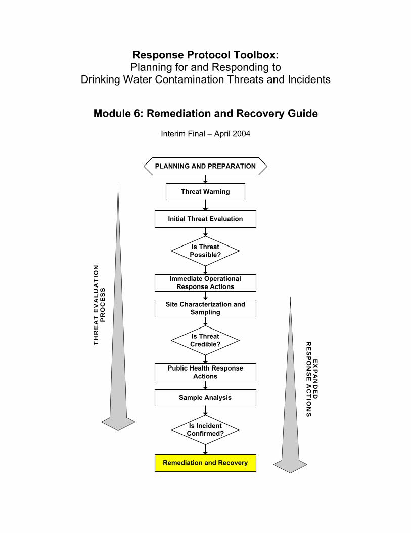
1.2 Process Overview This section provides an overview of the remediation and recovery process and summarizes the various documents that may be used to support remediation and recovery activities. This overview is intended to familiarize the reader with the entire process so that in subsequent sections, details of the steps can be understood in the context of the overall framework.
The need to initiate a remediation and recovery process will be determined when a contamination incident is confirmed. Immediate operational and public health response actions (Module 5) will precede remediation and recovery activities, and will likely continue during these activities.
Once contamination is confirmed, remediation and recovery must follow. The goal of remediation and recovery is to return the water supply system to service as quickly as possible while protecting public health and minimizing disruption to normal life (or business continuity). During the remediation and recovery stage of the threat management process, the immediate urgency of the situation has passed, and the magnitude of the remedial action requires careful planning and implementation. While rapid recovery of the system is crucial, it is equally important to follow a systematic process that establishes remedial goals acceptable to all stakeholders, implements the remedial process in an effective and responsible manner, and demonstrates that the remedial action was successful. This module describes the elements of such a systematic process.
17 Interim Final – April 2004
MODULE 6: Remediation and Recovery Guide
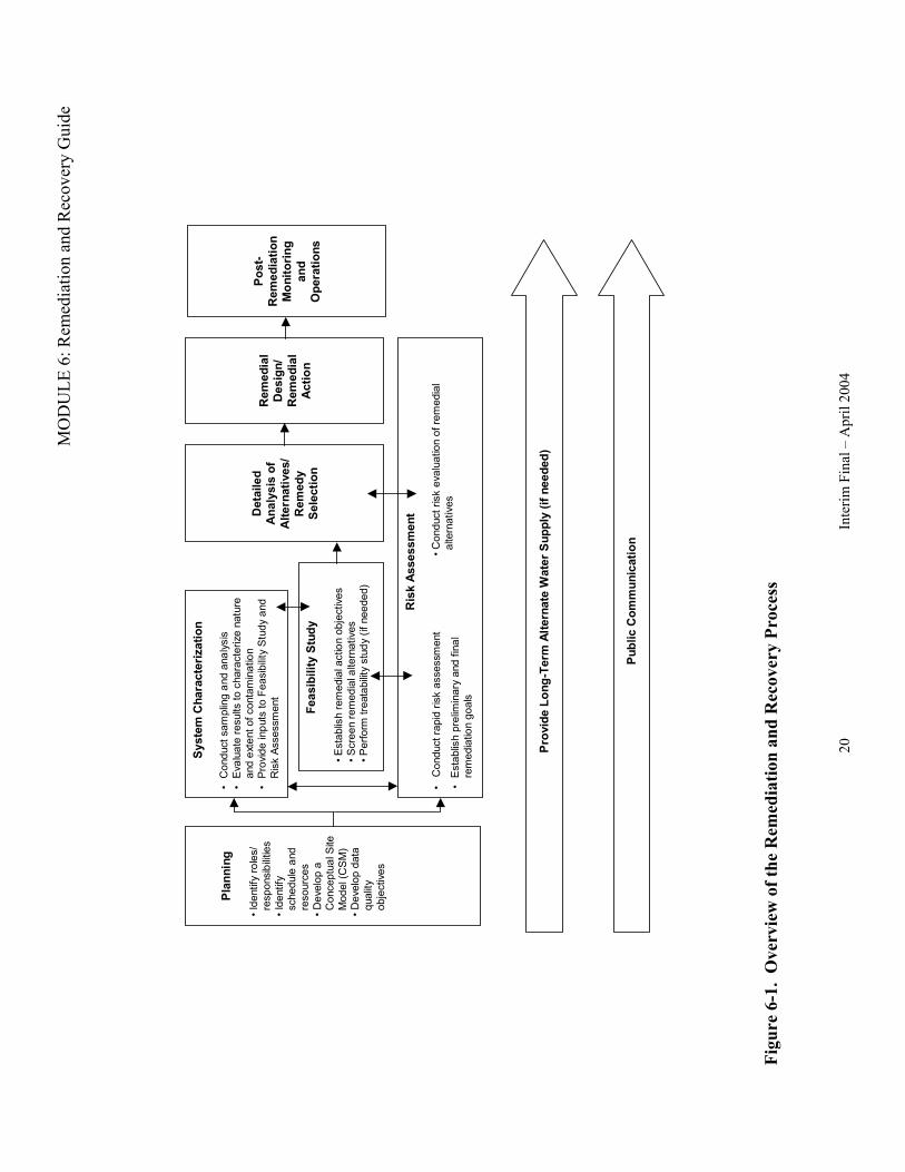
The remediation and recovery process is designed to address extensive contamination at concentrations that pose immediate and/or long-term risks to human health and the environment. The process is applicable to remediation of source water, treatment plant infrastructure, and/or water distribution systems. The process is described as a sequence of steps that should be implemented as quickly as possible to restore the drinking water resource. A flow chart depicts the remediation and recovery process (Figure 6-1), and key steps are summarized below.
• Ensure Long-Term Alternate Water Supply – While remediation is being carried out, a long-term alternate supply of domestic water (potable water) may be needed. A long-term alternative domestic water supply may differ from the short-term water supply described in Module 5. The need for a long-term alternative supply will depend on the nature and severity of the contamination event, the status of the water supply and the water distribution system, and the length of time needed to complete the remedial response and return the system to normal operation.
• Conduct System Characterization/Feasibility Study (SC/FS) – The SC/FS provides a detailed assessment of the nature and extent of contamination and screens for candidate treatment options.
• Conduct Risk Assessment – Risk assessment activities are used in tandem with the SC/FS to help establish preliminary remediation goals (PRGs), inform data collection activities, and select an appropriate remedy.
• Conduct Detailed Analysis of Alternatives – Candidate cleanup approaches and alternatives are evaluated and compared with remediation goals and other criteria, such as protectiveness and ease of implementation, to help choose the best remediation approach.
• Select Remedy– The preferred remedy is identified based on the Alternatives Analysis and the proven effectiveness of remediation technology for the specific contaminant.
• Prepare Remedial Design – Plans and specifications for applying selected remedies are prepared
• Undertake Remedial Action – Implementation and completion of cleanup activities include both treatment of the contaminated water and rehabilitation of system components. Following implementation of the remedy, it should be confirmed that the response actions have restored the drinking water system, before the system can return to normal operation.
• Conduct Post-Remediation Monitoring and Operations Assessment - After site remediation actions are complete, monitoring of the system should be done to ensure that all actions are effective and operating as planned.
• Provide Public Communication – During remedial activities and before the water system is returned to normal operations, the water utility should communicate with and
18 Interim Final – April 2004
MODULE 6: Remediation and Recovery Guide
provide outreach to the community to restore public confidence in the water system and the quality of the water.
The sections of this module provide basic guidance on how to implement the remediation and recovery process. The approach is modeled in part after the Superfund hazardous substance response protocol given in the National Oil and Hazardous Substances Pollution Contingency Plan at 40 CFR Part 300, Subpart E. This plan, also known as the National Contingency Plan or NCP, describes the Superfund remedial response program under the Comprehensive Environmental Response, Compensation, and Liability Act (CERCLA). While a contaminated water system would probably not be legally classified as a Superfund site, the Superfund model is used for the following reasons:
• At the remedial stage of the response to a contamination incident, the immediate public health threat will have been addressed through appropriate response actions, as discussed in Module 5. To implement a final remedy, it will be important to follow a systematic process involving careful planning.
• Remediation professionals, who will likely be involved in the response action, are already familiar with existing hazardous substance response protocols.
• When US EPA is involved in response to a contamination incident, the Federal Response Plan (FRP) requires the Agency to use the NCP structure.
• Most states have programs for cleanup of sites contaminated by hazardous substances and many of these programs use processes similar to the federal Superfund process. While a contaminated water system likely would not fall under these programs, states might choose to adopt “Superfund-like” processes when they are responsible for remediation, because of their familiarity with these processes.
The degree to which remediation and recovery follows the model presented here will depend on the nature and extent of contamination. A small-scale incident might not involve all of the steps presented in Figure 6-1. For example, if the contamination is contained through immediate operational response and is confined to a well-defined area, extensive system characterization might not be necessary. The initial site characterization (see Module 3) could provide sufficient information to guide the process, eliminating the need to go through the more involved system characterization process. If treatment options for the contaminant of concern are known and well defined, then the feasibility study and analysis of alternatives could be combined.
Even when all steps are necessary, the streamlined model presented here describes a remediation and recovery process that is reduced in scale, scope, and duration from the Superfund process. Only in the most severe and extensive contamination incidents would the remediation and recovery process be expected to require a period of time approaching that of a typical Superfund remediation. Appendix 9.5 presents a hypothetical example of a contamination threat to a drinking water system, including remediation and recovery based on the model presented here. In the example, the remediation and recovery process is completed within a short time frame (90 days), even though most of the steps shown in Figure 6-1 are included.
19 Interim Final – April 2004
MO
DU
LE 6
: Rem
edia
tion
and
Rec
over
y G
uide
Plan
ning
• Ide
ntify
role
s/
resp
onsi
bilit
ies
• Ide
ntify
sc
hedu
le a
nd
reso
urce
s • D
evel
op a
C
once
ptua
l Site
M
odel
(CS
M)
• Dev
elop
dat
a qu
ality
ob
ject
ives
• i
lis
•
li
i•
i
• id
ri
/ /
il a
li
(i)
il
i
• i
ii
l
Syst
em C
hara
cter
izat
ion
Con
duct
sam
plng
and
ana
ysEv
aua
te re
sults
to c
hara
cter
ize
natu
re
and
exte
nt o
f con
tam
nato
n Pr
ovde
inpu
ts to
Fea
sibi
lity
Stu
dy a
nd
Ris
k As
sess
men
t
Ris
k As
sess
men
t
Con
duct
rap
sk a
sses
smen
t
Det
aile
d A
naly
sis
of
Alte
rnat
ives
Rem
edy
Sele
ctio
n
Rem
edia
l D
esig
nR
emed
ial
Act
ion
Feas
ibili
ty S
tudy
• Est
abls
h re
med
ial a
ctio
n ob
ject
ives
• S
cree
n re
med
iate
rnat
ives
• P
erfo
rm tr
eata
blit
y st
udy
f nee
ded
• Con
duct
rsk
eva
uato
n of
rem
edia
l al
tern
ativ
es
Est
abls
h pr
elm
inar
y an
d fn
are
med
iatio
n go
als
Post
-R
emed
iatio
n M
onito
ring
and
Ope
ratio
ns
Publ
ic C
omm
unic
atio
n
)Pr
ovid
e Lo
ng-T
erm
Alte
rnat
e W
ater
Sup
ply
(if n
eede
d
Figu
re 6
-1.
Ove
rvie
w o
f the
Rem
edia
tion
and
Rec
over
y Pr
oces
s
20
Inte
rim F
inal
– A
pril
2004
MODULE 6: Remediation and Recovery Guide
1.3 Organization This module is organized into nine sections as described below. Planners and response action personnel are encouraged to review this module in its entirety, as well as the other modules in the Response Protocol Toolbox, to obtain a comprehensive understanding of the remedial response approach for dealing with water contamination threats.
Section 1: Introduction and Overview: discusses the purpose of this module, provides an overview of the remediation and recovery process, and describes the overall organization of the module. The overview is intended to acquaint the reader with the entire process so that details described in subsequent sections can be understood in the context of the overall process.
Section 2: Planning: discusses planning for remediation of a drinking water system after an intentional contamination incident. Planning involves developing a framework for ensuring that the right type, quantity, and quality of information are obtained to support remedial decisions. This section also discusses roles and responsibilities during the remedial process and summarizes the types of documentation that may be produced during the process.
Section 3: Risk Assessment, System Characterization, and Feasibility Study: discusses the SC/FS and integration of risk assessment into the remedial process. This section also discusses the use of treatability studies when an unproven remediation technology is being considered.
Section 4: Analysis of Alternatives and Remedy Selection: describes a flexible sequence of steps designed to select the appropriate remedial response to address contaminated drinking water and contaminated water system components (e.g., storage tanks, filters, pipes, pumps, etc.). These steps include a detailed analysis of candidate technologies and remedial options, followed by remedy selection.
Section 5: Remedial Design, Remedial Action, and Post-Remediation Monitoring and Operations: discusses remedial design, implementation/completion of the selected remedy, and operation and maintenance (O&M) of the remediation system. This section describes contaminant residuals that could be generated during remedial action and the regulations that should be considered when managing the residuals as waste. Guidance is presented on determining attainment of the remediation goal(s) through post-remediation monitoring. Special considerations for return to normal operations are discussed.
Section 6: Long-Term Alternative Domestic Water Supply: describes criteria for determining if a long-term alternate water supply is necessary and describes contingency planning, public communication, and long-term
21 Interim Final – April 2004
MODULE 6: Remediation and Recovery Guide
consideration where a “do not drink” or “do not use” determination has been made.
Section 7: Public Communication: presents guidance on maintaining effective public communication during the remedial process and return to normal operations.
Section 8: References and Resources: lists the references used in the development of this module and additional information resources.
Section 9: Appendices: provides additional information and materials that may help in preparing for remediation and recovery of a contaminated water system.
22 Interim Final – April 2004
MODULE 6: Remediation and Recovery Guide
2 Planning 2.1 Elements of Planning Systematic planning is a common sense approach designed to ensure that preparation and response activities are known in advance of an incident, so that if an incident occurs, the response can be swift, thorough and effective. The degree of planning required depends upon the type and complexity of potential contamination incidents, the human health and environmental risks, and the resources available to deal with the incident.
Systematic planning can be used to ensure that decision makers have accurate, sufficient, and timely information to support later decision making involving system characterization, remediation, and recovery. The level of planning detail that is required will depend on how important the information is, and how it is going to be used. The outputs of systematic planning are required as inputs to the various planning documents (see Section 2.3 and Table 6-1) used throughout the remediation and recovery process.
Systematic planning is important for successfully executing water system characterization and remediation activities that rely on rapid data collection and decision-making. US EPA’s Quality System web site includes documents on systematic planning (US EPA, 2004i, http://www.epa.gov/quality/). Other similar planning processes may be appropriate based on the requirements and responsibilities of the lead agency and the laboratories used to support the remedial process.
Much of the information needed to plan for water system remediation and recovery should have been developed and included in the water utility’s Emergency Response Plan (ERP). The ERP is developed or revised in response to the requirements of the Public Health Security and Bioterrorism Preparedness and Response Act of 2002 (PL 107-188, June 12, 2002). Information that should be included in the ERP includes: identification of planning partners, system-specific information (e.g., system maps and drawings), alternative water sources, chain-of-command, and communication processes. Guidance on ERPs may be found in Large Water System Emergency Response Plan Outline: Guidance to Assist Community Water Systems in Complying with the Public Health Security and Bioterrorism Preparedness and Response Act of 2002 (US EPA, 2003e, http://www.epa.gov/safewater/security/pdfs/erp-long-outline.pdf). Another resource is Emergency Response Plan Guidance for Small and Medium Community Water Systems to Comply with the Public Health Security and Bioterrorism Preparedness and Response Act of 2002 (US EPA, 2004l, http://www.epa.gov/safewater/security/pdfs/guide_small_medium_erp.pdf).
Key elements of a systematic planning process include:
• Identifying and involving the decision makers and support personnel – As described in Section 2.2 of this module, State and local governments will have initial and primary authority for consequence management in the event of a terrorist attack against a drinking water facility or infrastructure. If Federal assistance is provided under the authorities of the Stafford Act, then lead agencies and associated personnel will be established as specified in the FRP (FEMA, 2003, http://www.fema.gov/pdf/rrr/frp/frp2003.pdf).
• Identifying the schedule and resources – The lead agency will work in partnership with support agencies to establish schedules and milestones. Funding guidelines are given in the FRP (FEMA, 2003, http://www.fema.gov/pdf/rrr/frp/frp2003.pdf), Terrorism Incident Annex, Section VI (“Funding Guidelines”).
• Describing the goal(s) and objective(s) – The goal of remediation and recovery is to return the system to service as quickly as possible – providing safe, reliable drinking water – while protecting public health and minimizing disruption to normal life (or business continuity). However, for a complex site or a high concentration contamination incident, it may be necessary to establish intermediate/tiered goals such as first treating the water for non-drinking use (e.g., for sanitation and fire protection), followed by a secondary goal of treating the water for consumption. Goals should be specified in both qualitative terms (e.g., restoration of fire protection and basic sanitation) and in quantitative terms (e.g., concentration-based remediation goals for the water, system components, and affected environmental media).
• Developing a Conceptual Site Model (CSM) – A key step in the planning process is developing a CSM. A CSM is used to organize information that is already known about a site and to identify data gaps. A CSM is a basic description of how contaminants enter a system, their fate and transport within the system, the locations where exposure to the contaminant(s) is likely to occur, and the exposure routes of concern (e.g., dermal, ingestion, or inhalation). The CSM provides an essential framework for assessing risks from contaminants, developing remedial strategies, determining source control needs, and deciding how to address unacceptable risks. The guidance provided in Module 5, Section 3, for assessing the public health consequences of a drinking water contamination incident may also be useful for developing a CSM.
Once the contamination event is confirmed, but before implementing a final remedial response, the investigation/cleanup team should assemble existing information into the CSM. An initial CSM can be developed as soon as the contamination threat is confirmed (e.g., hours to days). The CSM should be refined throughout the remedial process as new information is obtained. The CSM will likely be developed by an inter-organizational team, under the direction of the lead agency. The CSM team may include representatives from the primacy agency/health department, the drinking water utility, site remediation specialists, and technical assistance providers.
Specific information to be collected for the CSM includes:
- Configuration of the water supply system (e.g., physical location of pipes in the distribution system). An up-to-date hydraulic model of the water system, if one is available, will be valuable, although maps may be the best source of information for many systems.
- The properties of contaminants confirmed or suspected in water (e.g., density, solubility, vapor pressure, Henry’s Law Constant, etc.). One source for information on chemical properties is US EPA’s Water Contaminant Information Tool (WCIT).
The WCIT is currently under development (see Module 2, Appendix 8.9 for more information). Other sources of contaminant information that might be used in the interim include: http://www.bt.cdc.gov/agent/agentlistchem.asp (CDC, 2003); and http://www.atsdr.cdc.gov/ (CDC, 2004). Module 5, Section 3.1 includes a comprehensive discussion of contaminant properties related to public health response, risk assessment and the development of the CSM.
- Point(s) and times of contaminant introduction into the system (source characterization). Note that contamination could be introduced at any point within the system, including source water (e.g., stream, river, spring, reservoir, impoundment, or aquifer (wells)), treatment plant, storage systems, and/or the distribution system (e.g., transmission mains, service connections, storage tanks, etc.).
- Points and pathways of exposure as well as potentially exposed populations.
- Risks, with the primary focus on human health and the secondary focus on ecological or economic consequences.
The CSM is documented in the system characterization documents (see Sections 3.2.1 and 3.3.4 of this module) by written descriptions of site conditions and supported by maps, cross sections, engineering drawings, analytical data, site diagrams, and modeling results that illustrate location, concentrations, and direction and rate of movement of the contamination. Much of the information that would support the development of a CSM should be readily available from the facility’s existing ERP and from information generated as part of the initial site characterization (Module 3).
The characterization/cleanup team uses the CSM as an input to the system characterization, sampling plan development, and risk assessment activities. The CSM serves several purposes – as a planning instrument; as a modeling and data interpretation tool; and as a means of communication among members of a project team, decision makers, stakeholders, and field personnel. For more information on CSMs including an example, see pages 2-7 and 2-8 of Guidance for Conducting Remedial Investigations and Feasibility Studies under CERCLA, Interim Final (US EPA, 1988a, http://www.epa.gov/superfund/action/guidance/remedy/rifs/overview.htm).
• Identifying the type of data needed – It will be necessary to identify the kinds of information needed, the sources of information, and confirm that appropriate sampling and analysis methods exist. For example, information may be needed on the physical properties of the affected media, flow rates, chemical and/or biological characteristics, and inputs necessary for models and risk assessments. An assessment should be made regarding the extent to which existing data can be used to support decision-making.
• Identifying constraints on data collection – Limitations that could affect data collection should be evaluated. Examples of limitations include resource or time constraints,
practical constraints such as physical access to sampling locations, environmental conditions (e.g., weather), and availability of equipment and personnel.
• Determining the data quality needed – For each type of data to be collected, the data quality, meaning the performance and acceptance criteria for useable data, should be specified and clearly documented. The acceptable level of uncertainty in the data should be specified.
• Determining the quantity of data needed – The quantity of data refers to the total number of samples and/or measurements that will be necessary. For practical reasons and to expedite field activities under emergency conditions, the number of samples obtained during the initial phases of the system characterization may be based on judgment of the characterization team. However, the number of samples needed for the detailed system characterization and demonstration that remediation goals have been achieved may be based on statistical sampling design. For more information on sampling designs, consult Guidance for Choosing a Sampling Design for Environmental Data Collection (US EPA, 2002f, http://www.epa.gov/quality).
• Describing how, when, and where the data will be obtained, and defining the boundary of the study – Outputs of the various planning steps are used as inputs to develop sampling plans to support each stage of the system characterization and remediation process. Sampling plans may be necessary at various stages including initial site characterization (see Module 3), system characterization to support remedial response, and post-remediation to confirm attainment of remediation goals.
• Specifying quality assurance and quality control activities to assess the quality performance criteria – Quality assurance (QA) and quality control (QC) activities should be specified in a Quality Assurance Project Plan (QAPP) or similar document and implemented to ensure that data collection activities are conducted correctly and can be assessed against performance criteria. For example, QA/QC activities could include the preparation and analysis of field and laboratory control samples, chain-of-custody procedures, and technical system performance audits and evaluations. Using a “graded” approach, the QAPP and related planning documents need only contain information necessary to address the work to be performed, thus facilitating more rapid development of plans and implementation of field activities.
• Identifying and selecting analytical laboratories – Planning documents should identify those laboratories that have the capability to analyze the samples and meet the performance criteria established in the planning process, given the specific contaminants confirmed or suspected. In the case of complex or exotic contaminants, there may be a limited number of laboratories available to provide analysis within the necessary response time. Module 4 provides an extensive discussion on the nature and capabilities of laboratory infrastructure in the U.S. and may be of use in identifying appropriate laboratories. Another source is US EPA’s Compendium of Environmental Testing Laboratories (http://www.epa.gov/compendium).
• Planning for data quality assessment – Project-specific plans should describe methods for data analysis, evaluation, and assessment against the intended use of the data and quality acceptance/performance criteria.
2.2 Roles and Responsibilities The remediation and recovery process is implemented when a contamination incident has been confirmed. For a confirmed incident, an agency external to the water utility may assume the responsibility for coordinating the response under an Incident Command System (ICS). Figure 62 depicts an example of unified command under ICS that might be assembled during the remediation and recovery phase (see also Module 1, Section 4.4). Note that while Figure 6-2 shows a hierarchical organizational structure, significant coordination and communication is necessary among the various levels of the ICS.
Structure for Incident Command for Remediation and Recovery
Incident Commander from Unified Command
(EPA, FBI, Health, Utility)
i ii
Li
i i i
ical iili
ii ( )
ii
li
(i )
Poi
l
l
i
Informat on Off cer or Joint Informat on Center
aison Officer from Unified Command
Safety Off cer from Unified Command Operat ons Sect on
Techn Spec alist from water ut ty
Agency Representat ve from util ty WUERM
Water Util ty Emergency Operat ons Center
EOC Staff
Utility P ant Operat ons
Utility Laboratory es
Laboratory nt of Contact
Law Branch
Hazmat Group
Public Hea th Group
ExternaLaboratory
Laboratory Point of Contact
Other agency representat ves
Figure 6-2. Incident Command Structure for Remediation and Recovery Activities
Whether the local, State, or Federal government will exercise primary authority will depend on the kind and size of the incident and resource needs for remediation and recovery. State and
27 Interim Final – April 2004
MODULE 6: Remediation and Recovery Guide
local governments have primary responsibility for consequence management, including remediation and recovery activities. State and local emergency operations plans generally establish direction and control procedures for their agencies using an ICS. In many States, State law or local jurisdiction ordinances will identify, by organizational position, the person(s) that will be responsible for serving as the incident commander. In most cases, the incident commander will come from the State or local organization that has primary responsibility for managing the emergency situation.
State assistance may be provided to local governments in responding to a terrorist threat or recovering from the consequences of a terrorist incident, as in any natural or man-made disaster. The governor, by State law, is the chief executive officer of the State or commonwealth and has full authority to discharge the duties of his or her office and to exercise all powers associated with the operational control of the State’s emergency services during a declared emergency (FEMA, 2001, http://www.fema.gov/pdf/rrr/conplan/conplan.pdf). State agencies are responsible for ensuring that essential services and resources are available to the local authorities and Incident Commander when requested.
If the magnitude of the remediation and recovery efforts exceeds the capabilities and resources of the local and State governments, or when Federal interests are involved, then the Federal Government will provide assistance under the FRP, when activated under the Stafford Act (FEMA, 2003, http://www.fema.gov/pdf/rrr/frp/frp2003.pdf). The FRP provides the mechanism for federal departments and agencies to coordinate delivery of Federal assistance and resources to augment efforts of State and local governments overwhelmed by a major disaster or emergency, including a terrorist act. Nongovernmental organizations such as the American Red Cross can also be mobilized under the FRP. When the FRP is activated, a single federal agency will serve as the overall lead federal agency, coordinating the efforts of other agencies, including lead agencies with responsibility for managing and coordinating a specific function and support agencies who provide technical support or take on specific tasks. Additional information on the FRP is given in Module 1, Appendix 6.2, including how the FRP is activated and under what circumstances.
Roles and responsibilities for key local, state, and federal departments and agencies in supporting water system remediation and recovery are summarized below.
Water Utility – The water utility will possess the most detailed first-hand knowledge and technical expertise regarding the configuration and operation of the water source, storage, treatment, and distribution systems. Accordingly, the WUERM, Water Utility Emergency Operations Center Manager, and other water utility personnel may serve as technical advisors within the ICS and provide support to lead agency personnel responsible for characterization, remediation, and recovery of a contaminated water system. If Federal assistance is provided under the authorities of the Stafford Act (42 U.S.C. §5121, et seq.), then responsibility for specific tasks most likely will be delegated to the water utility by the Department of Homeland Security (DHS)/Federal Emergency Management Agency (FEMA) or US EPA (who will support long-term site restoration and environmental cleanup). The FRP outlines how the Federal Government implements the Stafford Act.
Pre-planning is perhaps the most important remediation planning activity that a water utility can do. The water utility should play a key role in planning for a remedial response to contamination, including evaluating containment options and ensuring rapid access to the site, as well as providing operating records, engineering drawings, etc. that may be needed by response action personnel. This type of planning differs from that depicted in Figure 6-1 and Section 2 of this module because it is done not only during remediation, but also in anticipation of potential future remediation activities.
State and Local Authorities – State and local authorities maintain initial responsibility for managing domestic incidents. The Federal Government will assist State and local authorities when their resources are overwhelmed or when Federal interests are involved. In those cases, the local or state agencies (e.g., local health department) should work in partnership with the lead federal agency.
Federal Government: Key areas of responsibility for Federal government agencies that would potentially support water system remediation and recovery efforts are highlighted below:
• Department of Justice (DOJ)/Federal Bureau of Investigation (FBI) – The DOJ is the lead federal agency for threats or acts of terrorism within U.S. territory. DOJ assigns lead responsibility for crisis management to the FBI, which acts primarily in a law enforcement capacity. Crisis management refers to measures to identify, acquire, and plan the use of resources needed to apprehend and prosecute the perpetrators. In this role, the FBI operates as the on-scene manager for the Federal Government.
• Department of Homeland Security (DHS)/Federal Emergency Management Agency (FEMA) – The DHS supports the overall lead federal agency by operating as the lead agency for consequence management until the overall lead federal agency role is transferred to DHS. FEMA, a branch of the DHS, supports the lead federal agency for “consequence management” throughout the Federal response or serves as the lead federal agency when the Attorney General transfers the role to DHS. Consequence management refers to measures to protect public health and safety, restore essential government services, and provide emergency relief to governments, businesses, and individuals affected by the consequences of terrorism.
• Department of Health and Human Services (HHS) - HHS will activate technical operations capabilities to support the Federal response to threats or acts of chemical, biological, and radiological terrorism. HHS may coordinate with individual agencies, such as Centers for Disease Control and Prevention (CDC). The CDC is authorized by the HHS Health and Medical Services Support Plan for the Federal Response to Acts of Chemical/Biological Terrorism to use the structure, relationships, and capabilities described in the HHS plan to support response operations.
• US Environmental Protection Agency (US EPA) – US EPA will activate technical operations capabilities to support the Federal response to acts of chemical, biological, and radiological terrorism. US EPA may coordinate with individual agencies identified in the
29 Interim Final – April 2004
MODULE 6: Remediation and Recovery Guide
NCP1 to use the structure, relationships, and capabilities of the National Response System as described in the NCP [40 CFR Part 300 subpart B] to support response operations. If the NCP is implemented, then: - The Hazardous Materials On-Scene Coordinator (in the case of immediate
responses) or Remedial Project Manager (in the case of longer term remedial actions) under the NCP will coordinate the NCP response with the DHS official who is responsible for on-scene coordination of all Federal support to State and local governments; and
- The NCP response may include risk assessment, consultation, agent identification, hazard detection and reduction, environmental monitoring, decontamination, and long-term site restoration (environmental cleanup) operations.
• US Army Corps of Engineers (USACE) - Under FRP Emergency Support Function (ESF) #3, Public Works and Engineering Annex, the USACE serves as the primary agency responsible, in part, for emergency restoration of critical public facilities. Activities can include the temporary restoration of water supplies and emergency contracting to support public health and safety, such as providing for potable water.
In summary, no single agency or organization at the Federal, State, local, or private-sector level possesses the authority and expertise to unilaterally implement remediation and recovery actions. If Federal assistance is provided under the authority of the Stafford Act, then responsibility for specific tasks will be delegated by the lead agency to those entities that have the skills and resources to implement them.
2.3 Documentation The specific documentation and actions needed to conduct the remediation and recovery of a contaminated water system will depend upon site-specific circumstances and the requirements specified by the lead agency. Table 6-1 describes the various documents that could be used to support remediation and recovery activities. In many cases, lead agencies such as DHS or US EPA, rather than the utility, will be responsible for developing these planning documents or for delegating that responsibility to a supporting agency. However, the utility will have an important role in the planning and implementation of remedial activities, and thus should have an understanding of the planning process to better support the effort.
1 Agencies listed in the NCP include: United States Coast Guard, FEMA, the Department of Defense, the Department of Energy, the United States Department of Agriculture, the Department of Commerce, HHS, the Department of Interior, DOJ, the Department of Labor, the Department of Transportation, the Department of State, Nuclear Regulatory Commission, and General Services Administration.
30 Interim Final – April 2004
MODULE 6: Remediation and Recovery Guide
Table 6-1. Documentation of Planning, Implementation, and Assessment Activities for Water System Remediation and Recovery
Remedial Process Activity
Supporting Documentation Purpose
Module 6 Section
System Characterization Work Plan
Documents decisions made during the planning/scoping process and presents anticipated future tasks that are part of system characterization and the feasibility study. Serves as a tool for assigning responsibilities and setting schedule and costs.
3.2.1
Sampling and Analysis Plan (SAP) •
•
Quality Assurance Project Plan (QAPP) Field Sampling Plan (FSP)
The SAP consists of two parts: (1) QAPP that describes the policy, organization, functional activities, and quality assurance and quality control protocols necessary to ensure data collected will meet user needs; and (2) the FSP that provides guidance for all fieldwork by defining in detail the sampling and data-gathering methods to be used.
3.2.1
Health and Safety Plan
Identifies personnel, training and medical monitoring requirements, equipment, site control measures, and other procedures to conform to performing organization's health and safety program and applicable Occupational Safety and Health Administration (OSHA) requirements.
3.2.1
System Characterization/ Feasibility Study (SC/FS)
System Characterization/ Feasibility Study Report
Identifies preliminary remediation goals (PRGs) and presents outputs of screening of alternatives. Used as input to risk assessment and documentation of data collection and analysis in support of the Remedy Selection Study.
3.3.4
Treatability Study Work Plan
Specifies test objectives, specialized equipment and materials necessary, treatment test procedures, parameters to measure, analytical methods, data management, data analysis and interpretation, health and safety, and residuals management.
3.3.3 Treatability Study
Treatability Test Evaluation Report
Describes testing performed, results of the tests, and how the results would affect the
3.3.3
being considered. Describes effectiveness of the treatment technology and estimated costs for applying the technology for remediation.
evaluation of the remedial alternatives
System Remediation
Remedy Selection Report
Presents a comparative analysis of remedial alternatives and describes those actions that will satisfy the remedial action objectives.
4.3
31 Interim Final – April 2004
MODULE 6: Remediation and Recovery Guide
Remedial Process Activity
Long-Term Alternate Water Supply Community Relations/ Communication Plan
Remedial Design Work Plan and supporting documentation
Supporting Documentation
Remedial Action Work Plan and Report(s)
Post Remediation Monitoring Plan
Contingency Plan for Long-Term Alternate Water Supply* Communications Strategy
Documents, specifications, and drawings that detail the steps to be taken during the remedial action. Other documents could include: Design Criteria Report, Basis of Design Report, Specifications, Drawings and Schematics, Construction Quality Assurance Plan, Draft Operation and Maintenance (O&M) Manual, Remedial Action Solicitation Package, Remedial Action Schedule, and Remedial Action
Purpose
Cost Estimate. Describes all remedial response plans and actions taken and the basis for determining that the remediation goals were (or were not) attained. Describes sampling activities of remediated area and critical use areas to evaluate continued success of remedial action. Identifies possible sources of alternate water supply.
Communicates revised public notifications, water supply alternates, remediation and recovery options, estimated time to return to normal operation, and information on continued monitoring and analysis of the water system after remediation.
5.1
Module 6 Section
5.2
5.4
6
7
(See also Module 5, Section 5)
* A separate plan may not be necessary if identification of alternative water supplies is addressed in the utility’s Emergency Response Plan as recommended in Large Water System Emergency Response Plan Outline: Guidance to Assist Community Water Systems in Complying with the Public Health Security and Bioterrorism Preparedness and Response Act of 2002 (US EPA, 2003e, http://www.epa.gov/safewater/security/pdfs/erp-long-outline.pdf) and Emergency Response Plan Guidance for Small and Medium Community Water Systems to Comply with the Public Health Security and Bioterrorism Preparedness and Response Act of 2002 (US EPA, 2004l, http://www.epa.gov/safewater/security/pdfs/guide_small_medium_erp.pdf).
3 Risk Assessment, System Characterization, and Feasibility Study
After a contamination incident has been confirmed, additional information and data will be needed to support remediation and recovery actions. This additional information and data will be obtained via a System Characterization/Feasibility Study (SC/FS):
• The system characterization serves as the mechanism for collecting data to more fully characterize system conditions, determine the nature and extent of the contamination, and assess risk to human health and the environment.
• The feasibility study is the mechanism for the development, screening, and evaluation of candidate remedial technologies or actions. If necessary, it may include conducting treatability testing to evaluate the potential performance and cost of the treatment technologies that are being considered.
Risk assessment activities also will be conducted during the SC/FS process to evaluate the reduction in risk resulting from the immediate operational response actions, to aid in establishing risk-based remediation levels, and to assess potential risk reductions from implementation of a long-term remedy.
The various steps, or phases, of the SC/FS process are summarized in the following sections. As shown in Figure 6-1, the system characterization and feasibility study must be conducted together at the same time. The reason for doing both together is that data collected for system characterization also are needed for the risk assessment and for the development of remedial alternatives in the feasibility study. The outputs of system characterization in turn affect the data needs and scope of treatability studies (if needed) and additional field investigations (if needed).
The overall approach to system characterization through remediation is similar to that used in the hazardous substance response protocol in the NCP for a Superfund remedial investigation and feasibility study (see US EPA, 1988a, http://www.epa.gov/superfund/action/guidance/remedy/rifs/overview.htm).
3.1 Risk Assessment Upon confirmation of a contamination incident, the lead agency for consequence management will quickly assess the risks posed to on-site workers and the public. The lead agency typically will be DHS/FEMA or US EPA in consultation with public health agencies such as the CDC. The rapid risk assessment will help guide response actions. During the remedial response phase, additional risk assessment may be necessary to evaluate risk reduction resulting from the immediate operational response actions, to help establish PRGs, and to assess potential risk reductions from implementation of a long-term remedy. The relationship between risk assessment activities and remedial response actions was shown previously in Figure 6-1.
3.1.1 Rapid Risk Assessment US EPA is developing guidance and tools to help evaluate the risks associated with drinking water from systems affected by a contamination incident. The guidance is intended to help determine whether water contamination exists at levels sufficient to warrant further action and to evaluate the risks posed by the contaminants. Use of the Rapid Risk Assessment tools may significantly reduce the time it takes to complete the system characterization, remediation, and recovery. It will also provide a consistent basis for evaluating risks if multiple sites are involved. These tools are now being developed. When they become available, information on accessing them will be found at: http://www.epa.gov/ordnhsrc (US EPA, 2004h).
3.1.2 Integrating the System Characterization/Feasibility Study with Risk Assessment Data generated from the system characterization will be used as inputs to risk assessment activities. The outputs of the risk assessments will in turn be used to establish PRGs and to inform further field investigations. The outputs of the feasibility study will be a list of candidate technologies and remediation alternatives. Risk assessment tools will be used to evaluate the protectiveness of the proposed remedies.
Data generated during the SC/FS should therefore be usable for risk assessment. This means that the characterization team should plan to obtain data of sufficient type, quantity, and quality, collected at the necessary times and locations, to support the system characterization, feasibility study, and risk assessment efforts. This is discussed in detail in later sections.
3.1.3 Establishing Preliminary Remediation Goals (PRGs) Early in the remediation and recovery process, it will be necessary to establish long-term, media-specific target concentrations for use in screening and selecting remedial alternatives. Ideally, these target concentrations will be set at levels that result in acceptable risks to human health and the environment. Early development of these goals should help streamline the process of identifying candidate treatment technologies. These initial concentration goals are known as Preliminary Remediation Goals, or PRGs.
If the contaminant is known and an action level exists, then this action level could serve as a PRG. Examples of action levels include Maximum Contaminant Levels or MCLs for drinking water, or Effluent Limitations Guidelines for treated water. The action level may be based on a combination of factors including human health protection, technical feasibility, and/or ecological effects.
If an action level does not exist, then one approach for establishing a risk-based PRG is to perform risk calculations, in a manner similar to that used by US EPA in the Superfund program (US EPA, 1991, http://www.epa.gov/superfund/programs/risk/ragsb/index.htm). A risk-based PRG can be derived using risk equations that reflect the potential human health risk from exposure to a chemical, assuming certain characteristics of exposure (e.g., exposure pathway, exposure time and frequency, body weight, etc.). By setting the total risk for carcinogenic effects at a target risk level (e.g., 10-6 or 1 in 1,000,000), it is possible to solve the risk equation for the concentration term which is then used as the risk-based PRG. A similar approach is used to set PRGs based on noncarcinogenic effects (e.g., by setting the hazard index equal to 1).
3.1.4 Establishing Final Remediation Goals The final remediation goals will be established upon completion of the SC/FS and identification of the remedial action objectives (see Section 3.3.1). Final remediation goals should be based on acceptable exposure levels that are protective of human health and the environment. In the absence of established drinking water standards (such as MCLs and non-zero MCL Goals established under the Safe Drinking Water Act [SDWA]), decision makers should consider other criteria2, such as the following:
• For systemic toxicants, acceptable exposure levels could be set at concentration levels at which there is no excessive risk of adverse health effects to the human population, including sensitive subgroups such as children, during a lifetime or part of a lifetime of exposure.
• For known or suspected carcinogens, acceptable exposure levels are generally concentration levels that represent an excess upper limit of lifetime cancer risk to an individual of between 10−4 and 10−6 (1 in 10,000 and 1 in 1,000,000, respectively) based on the relationship between dose and response.
• Factors related to technical limitations, such as detection/quantification limits for contaminants.
• Potential exposure routes. Ingestion of contaminated water is the most obvious exposure route; however, for certain contaminants, the public could be exposed to the contaminant through inhalation and dermal contact through showering and bathing with the contaminated water. Recommended final remedial goals based upon ingestion, inhalation, and dermal exposure to contaminated water can be established using methodologies similar to those used by US EPA in the Superfund program (US EPA, 1989, http://www.epa.gov/superfund/programs/risk/ragsa/index.htm; US EPA, 2002h, http://www.epa.gov/superfund/programs/risk/ragse/index.htm). A remedial goal that will reflect the aggregate risk via multiple exposure pathways can be calculated utilizing standard exposure assumptions, and incorporating oral and inhalation toxicity information from sources such as US EPA’s Integrated Risk Information System (US EPA, undated a, http://www.epa.gov/iris/).
3.2 System Characterization The scope of the system characterization will generally be broader and more detailed than the initial pre-remedial site characterization (described in Module 3). The initial pre-remedial site characterization gathers information to help determine whether or not the threat is ‘credible.’ In contrast, the system characterization focuses on the nature, extent, and fate of particular contaminants in the water system and its components to support the selection of appropriate response and remediation actions. It is important to tailor the system characterization to specific conditions and circumstances within the system where contamination is likely to be found. It is equally important to establish the boundaries of the contamination to help define the extent of the remedial action.
3.2.1 System Characterization Planning Documents Planning is essential to successfully characterize the system and to select an appropriate remedial response. The outputs of the systematic planning process (Section 2 of this module) are used as
2 These criteria are modeled after US EPA’s risk and remediation goals found in the NCP, 40 CFR Part 300.430(e).
inputs to the planning documents. Several planning documents may be necessary to support the system characterization. These plans include the following:
• System Characterization Work Plan; • Sampling and Analysis Plan (SAP) comprising two parts: a Quality Assurance Project
Plan (QAPP) and Field Sampling Plan (FSP); and • Health and Safety Plan (HASP).
The level of detail necessary for these documents will depend on the amount and quality of information that results from the initial site characterization phase (see Module 3). Naturally, all data and information gathered to this point should inform the development of the System Characterization Work Plan, SAP, and HASP (if needed). The lead agency may also have requirements regarding the specific planning documents necessary for system characterization.
System Characterization Work Plan The System Characterization Work Plan documents information collected and decisions made during the systematic planning process, and describes anticipated future tasks. It also serves as a valuable tool for assigning responsibilities and setting the project's schedule and cost.
The primary users of the System Characterization Work Plan will be the lead agency for consequence management (usually either DHS/FEMA or US EPA at the federal level) and the project team that will execute the work. Secondary users of the System Characterization Work Plan include other groups or agencies serving in a technical advisory or review capacity, such as the water utility and local government agencies.
The System Characterization Work Plan should include the following elements:
• Introduction – A general explanation of the reasons for the system characterization study and the expected results or goals of the study process.
• System Description and Summary of Existing Data – A description of the configuration and physical setting of the system, a summary of the contamination event/history, and current situation and system condition.
• Initial Evaluation – The initial evaluation is based on the CSM and describes the source(s) or point(s) of contaminant introduction, boundaries of the affected area of the system, exposure pathways, and the preliminary assessment of consequences to human health, the environment, and system infrastructure.
• System Characterization Work Plan Rationale – Documents data needs for both the risk assessment and the treatment technology evaluation identified during the systematic planning process. The work plan rationale describes how the activities will satisfy data needs.
• System Characterization Tasks – Describes the tasks to be performed during the system characterization. This description incorporates characterization tasks identified in the
36 Interim Final – April 2004
MODULE 6: Remediation and Recovery Guide
SAP (see below) and the preliminary determination of tasks to be conducted after system characterization (e.g., risk assessment and modeling).
Appendix 9.1 provides a suggested format for the System Characterization Work Plan. The specific content of a given work plan and the individual tasks needed will depend on the specific situation and the drinking water system. Detailed guidance for the development of a work plan can be found in US EPA’s Guidance for Conducting Remedial Investigations and Feasibility Studies Under CERCLA (US EPA, 1988a, http://www.epa.gov/superfund/action/guidance/remedy/rifs/overview.htm).
Sampling and Analysis Plan (SAP) The SAP consists of two parts: (1) a QAPP that describes the policy, organization, functional activities, and QA and QC protocols necessary to achieve data quality objectives dictated by the intended use of the data; and (2) the FSP that provides detailed guidance for all fieldwork by defining the sampling and data-gathering methods to be used.
Quality Assurance Project Plan (QAPP) – The QAPP is a critical planning document for data collection for system characterization because it documents all project activities, including QA and QC activities. In the context of the SAP, QA is a system of management activities designed to ensure that collected data will be of the type and quality needed to support system characterization and remediation. QC is the overall system of technical activities that measures the attributes and performance (quality characteristics) of a measurement process against defined standards to verify that they meet the stated requirements established by the data user.
As recommended in the US EPA Guidance for Quality Assurance Project Plans, EPA QA/G-5 (US EPA 2002a, http://www.epa.gov/quality/qs-docs/g5-final.pdf), a QAPP is composed of four sections of project-related information called “groups,” which are subdivided into specific detailed “elements.” The groups and elements are summarized in the following subsections. See Appendix 9.2 for an outline of the elements of a QAPP.
• Project Management - This group of elements address project management, including the project history and objectives, roles and responsibilities of the participants, etc. These elements ensure that the project has a defined goal, that the participants understand the goal and the approach to be used, and that the planning outputs have been documented.
• Data Generation and Acquisition - These group elements address all aspects of project design and implementation. Implementation of these elements ensures that appropriate methods for sampling (as documented in the FSP), measurement, analysis, data collection or generation, data handling, and QC activities are used and are properly documented.
• Assessment and Oversight – These group elements include activities for assessing the effectiveness of implementation of the project and associated QA and QC activities. The purpose of assessment is to ensure that the QAPP is implemented as prescribed.
• Data Validation and Usability - The elements in this group address the QA activities that are conducted after the data collection or data generation phase of the project is
completed. Implementation of these elements ensures that the data conform to criteria specified in the QAPP, thus achieving the project objectives.
The QAPP should provide sufficient detail to demonstrate that: • The technical and quality objectives of system characterization are identified and agreed
upon; • The intended measurements, data acquisition, or data generation methods are appropriate
for achieving system characterization objectives; • Assessment procedures are sufficient for confirming that data of the type and quality
needed and expected are obtained; and • Limitations on the use of the data can be identified and documented.
Most environmental data collection and analysis operations involve the coordinated efforts of many individuals, including managers, engineers, scientists, statisticians, and others. The QAPP should integrate the contributions and needs of everyone involved in data generation and data usage into a clear, concise format of what is to be accomplished, how it will be done, and by whom. The QAPP should provide understandable instructions to those who implement the QAPP, such as the field sampling team, the analytical laboratory, and the data reviewers. The use of national consensus standards and practices is encouraged.
Field Sampling Plan (FSP) – The FSP defines in detail the sampling and data-gathering methods to be used in the system characterization effort. The FSP is more detailed than the Site Characterization Plan (described in Module 3,Section 4.1) used for initial water system characterization following a suspected water contamination incident. The FSP should include the following elements:
• System Description – This is a description of the water system and related information such as surrounding water sources, watersheds, and hydraulic flow patterns. Available schematics or maps detailing the water system will assist in subsequent sampling activity and identify probable transport pathways for contaminants. Similar system information is obtained when developing the CSM as described in Section 2 of this module. The system description also should include descriptions of specific data gaps and ways in which sampling is designed to fill those gaps. This discussion helps orient the sampling team in the field.
• Sampling Objectives – This section of the FSP should clearly and succinctly state the objectives and the intended uses of the sampling data.
• Sample Location and Frequency – This section of the FSP identifies the location and sampling frequency of each sample to be collected, organized by sampling matrix (i.e., media) and the constituents to be analyzed. While the primary sampling matrix will be water in most cases, there may also be a need to sample sediments, deposits in distribution system piping, the pipe itself, etc. A table may be used to clearly identify the number of samples to be collected along with the appropriate number of replicates, blanks, and other control samples. A water distribution system map should be included to show the locations of existing or proposed sample points.
38 Interim Final – April 2004
MODULE 6: Remediation and Recovery Guide
• Sample Identification – A sample identification system should be established. The sample identification should include the sample identification number, time of collection, date, a description of the sample matrix (e.g., water, sludge, filter media), analysis needed, preservative used (if any), name of the sample collector, and the project name or code. (See the “Sample Documentation Form” in Module 3, Appendix 8.4, as an example format for recording this information).
• Sampling Equipment and Procedures – Sampling procedures should be clearly written and described in the FSP. Step-by-step instructions for each type of sampling activity are necessary to enable the field team to gather data that will meet the data quality objectives. A list should include the equipment to be used and the material composition (e.g., Teflon, stainless steel) of the equipment, along with decontamination procedures. A sample collection kit, as described in Module 3, Section 3.2.1, illustrates the types of materials and supplies useful in collecting water samples. Collection of samples of matrices other than water may require additional materials and supplies.
• Sample Handling and Analysis – A table should be included in the FSP that identifies sample analysis methods to be used, sample preservation methods, types of sampling jars, shipping requirements, and holding times. The plan also should address procedures for documentation of field activities, chain-of-custody, and sample handling within the laboratory. See the chain-of-custody form in Module 3, Appendix 8.5, for recording this information.
As with the QAPP, development of an FSP involves the coordinated efforts and expertise of the individuals involved with field sampling, laboratory analysis, and oversight of the system characterization. Just as with the QAPP, the use of national consensus standards and practices is encouraged.
Health and Safety Plan (HASP) OSHA helps set and implement national safety and health standards for emergency responders. Foremost among these standards is the Hazardous Waste Operations and Emergency Response standard (29 CFR 1910.120(q)). Among other provisions, the standard requires entities engaged in emergency response to provide appropriate training to their workers, to use an ICS, to develop a written response plan (health and safety plan), and to provide workers with appropriate protective equipment.
One subset of emergency response personnel, known as “skilled support personnel,” support remediation and recovery efforts related to terrorism (National Clearinghouse for Worker Safety and Health Training, 2002, http://www.wetp.org/front/NIEHS_rev_010303.pdf). OSHA requires that skilled support personnel be trained at a minimum with an “awareness program” (see Hazardous Waste Operations and Emergency Response regulation, 29 CFR 1910.120(q)(4)). Additional training commensurate with worker responsibilities may be required. The safety of water utility personnel involved in emergency response activities should be addressed as part of the facility’s ERP.
Under the provisions of the FRP, OSHA may provide advice regarding hazards to persons engaged in response activities and take any other action necessary to ensure that employees are properly protected. However, deployed agencies are responsible for protecting the safety and health of their workers.
A HASP should include information regarding personnel roles, lines of authority and communication, site security and control, and medical and emergency alert procedures. The HASP should be developed for the specifics of the incident so that staff are aware of the common routes of exposure at a site and are trained in the proper use of safety equipment and protective clothing and equipment. Safe areas should be designated for washing, drinking, and eating. To minimize the impact of an emergency situation, field personnel should be aware of basic first aid and have immediate access to a first aid kit. A suggested format for a HASP is given in Appendix 9.3, and additional considerations are described in Module 4, Section 3.1.1.
The document entitled Occupational Safety and Health Guidance Manual for Hazardous Waste Site Activities was jointly developed by the National Institute for Occupational Safety and Health, OSHA, the United States Coast Guard, and US EPA (OSHA, 1985, http://www.osha.gov/Publications/complinks/OSHG-HazWaste/4agency.html). It is intended for those who are responsible for occupational safety and health programs at hazardous waste sites. While a contaminated water treatment site may not be a hazardous waste site, many of the health and safety considerations may be similar. Additional information from OSHA on safety issues related to emergency preparedness and response can be found at http://www.osha-slc.gov/SLTC/emergencypreparedness/index.html (OSHA, undated).
3.2.2 Implementing System Characterization During system characterization, the activities described in the planning documents will be implemented to define the nature, extent, and fate of contaminants in the dinking water system. As with the initial on-site activities, the system may be considered a crime scene by DOJ/FBI. In this case, on-site activities should be coordinated with DOJ/FBI or other law enforcement agencies (e.g., US EPA’s Criminal Investigation Division) that have authority for deciding what actions to take that may affect evidence-gathering/case development.
During system characterization, the System Characterization Work Plan and SAP are implemented and sampling data are collected and analyzed to determine to what extent a contaminated water system poses a threat to the public, remediation teams, or the environment. The major components of system characterization include:
• Conducting sampling in accordance with the FSP; • Analyzing samples in accordance with the FSP plan and QAPP; • Evaluating results of data analysis to characterize the site and conduct risk assessment;
and • Determining if data are sufficient for developing and evaluating potential remedial
alternatives.
Because contamination has been confirmed by this stage, some data will be available. Physical evidence at the site may be sufficient to tentatively identify the contaminant. “Presumptive” test information (e.g., indicator parameters or other semi-quantitative test method results) may
indicate the general type of agent such as radioactive, biological (vegetative cells, spores, viruses or protozoa), or chemical toxins. In some cases, a laboratory may have analytically confirmed the identity of the contaminant. If the contaminant remains unknown, then worst-case scenarios may need to be assumed. At this early stage, investigators should continue to think broadly and consider a wide array of possibilities, including multiple contaminants. For example, detection of chemical contamination does not necessarily rule out the possibility that biological or radiological contamination may be present as well.
To the extent possible, the system characterization should be expedited to quickly generate the information needed to select a remedy and restore safe and reliable drinking water to the affected community. One strategy for expedited system characterization is US EPA’s “Triad Approach.” The Triad Approach involves an integration of systematic planning (as described in Section 2.1), dynamic work plans, and rapid contaminant analysis to achieve a more streamlined, cost-effective remediation and recovery. For a small or uncomplicated contamination incident, or for discrete tasks within a complex contamination incident, the Triad Approach could enable system characterization activities to blend seamlessly into remediation activities. Additional information on the US EPA Triad Approach can be found at http://www.epa.gov/tio/triad/ (US EPA, 2004j).
Using the Triad Approach, a dynamic work plan guides the project team in making decisions in the field about how subsequent site activities will progress. A dynamic work plan relies upon the use of quick turn-around analytical services (if they exist and can meet analytical performance standards) to facilitate rapid analysis, and an overall compressed budget and schedule. A dynamic work plan can be formulated as a decision tree during the planning phase so that system characterization activities in the field will provide input to the maturing conceptual site model on a near real-time basis (e.g., hourly or daily). In a dynamic work plan, contingency plans are developed in advance to deal with potential events that are reasonably likely to occur during the course of site work, such as equipment malfunction, the unanticipated (but possible) discovery of additional contamination, etc.
The investigation methods that are used must meet the data needs established in the planning process. Support activities may need to be arranged before beginning the actual investigation in order to:
• Ensure access to all areas to be investigated; • Procure equipment and supplies in a timely manner; • Coordinate with analytical laboratories; • Procure on-site facilities for office and laboratory space, decontamination equipment,
sample storage, and utilities; and • Provide for storage and disposal of contaminated material (see also Section 5.3 of this
module, “Disposal of Remediation Residuals”).
Information about the physical characteristics of the system and affected media should be collected as needed to define potential transport pathways and exposed populations, and to provide sufficient engineering data for development and screening of remedial action alternatives (see also Section 3.3.2 of this module). The information needed will depend upon the nature of
the contaminant and the portion of the system in which contamination occurs (e.g., the source water, treatment plant, or distribution network). For example, if the contamination is confined to the distribution system, then information would be needed concerning water demand, population served, system configuration (i.e., map), miles and diameters of mains, number and location or booster pumps, materials of construction for pipes and fittings, and entry/exit points.
Geographic information system (GIS) mapping, coupled with hydraulic modeling software tools, can be used to combine analytical results and physical features to map, track, model, and estimate the flow and concentration of contaminants in source water and in the distribution system. PipelineNet and RiverSpill are examples of software tools that provide this modeling/GIS capability. Detailed information on GIS and related tools, and their capabilities and limitations, is provided in Module 5, Appendix 8.6.
Characterization should be sufficient to define the physical boundaries of the study area and to establish the physical system that will be the subject of remedial action. For example, contamination may be confined to a specified and isolated section of the distribution system, while the reservoir, storage tanks, and treatment plant are found to be “clean.” The final objective of the field investigations is to characterize the nature and extent of contamination so that informed decisions can be made concerning the level of risk presented by the site and the appropriate type(s) of remedial response. The results of the system characterization will be included in the SC/FS report (see Section 3.3.4).
3.3 Feasibility Study The feasibility study is the mechanism for development, screening, and evaluation of alternative remedial actions. It is conducted concurrently with system characterization and involves identifying remedial action objectives, identifying potential treatment technologies or other response actions that will satisfy these objectives, and screening the candidate technologies. The output of the feasibility study will be a list of remediation alternatives to be evaluated in greater detail during the Remedy Selection Study (see Section 4).
3.3.1 Establishing Remedial Action Objectives Remedial action objectives specify the contaminants and media of interest, exposure pathways, and remediation goals that permit a range of remedial alternatives to be developed. Note that the final remediation goals (expressed as a contaminant concentration in a medium) are a subset of the remedial action objectives. The remedial action objective depends on the exposure pathway. For example, a remedial action objective for contaminated water that will be treated for consumption will be different than a remedial action objective for contaminated water that will be treated and discharged to a river. In the former case, the remedial action objectives should be protective of public health, while in the latter case, ecological considerations may drive the objectives.
The final acceptable remediation goals should be based on a risk assessment or existing health or technology-based standards (see also Section 3.1.4 of this module). Ultimately, the degree of treatment necessary to negate or mitigate the public health effects will depend on system-specific factors such as the need to treat the water for consumption, treat to dispose/discharge, and the
42 Interim Final – April 2004
MODULE 6: Remediation and Recovery Guide
volume of the water (e.g., smaller volumes of water may be easier to send off site for disposal rather than try to treat on-site.).
3.3.2 Development and Screening of Remedial Alternatives During the system characterization, information on the physical and chemical characteristics of the contaminants present in the system should be reviewed and candidate remedial technologies should be identified. The objective of screening of remedial alternatives is to eliminate those remedial technologies that clearly are not applicable to the contamination incident. The remedial action objectives will drive the selection of candidate technologies. To be considered as a potential remediation option, a remediation technology should have the demonstrated ability to meet the remediation goals based on the contaminant concentrations present. In some cases, more than one technology may be needed. As discussed in Section 4, technologies to be considered may include not only those for treating (or otherwise handling) contaminated water, but also those for rehabilitating system components and dealing with other affected environmental media.
The efficacy of various treatment options for specific contaminants should be included in the WCIT, if they are available (see Module 2, Appendix 8.9 for more information on the WCIT). Pre-screening of remedial alternatives via the WCIT will streamline the processes of specifying a remediation level and selecting a remedy. However, there are substantial gaps in industry knowledge regarding the efficacy of various treatment processes for a significant number of contaminants of concern. Furthermore, the ability of a particular treatment option to reduce contaminant concentrations to the desired level will depend on the design and operation of the technology.
Remediation alternatives are developed by assembling combinations of technologies, and the media to which they would be applied, into remediation alternatives that address contamination on a system-wide basis. This process consists of six general steps outlined below:
1. Establish remedial action objectives specifying the contaminants and media of interest (e.g., water, infrastructure material, etc.), and PRGs (see Section 3.1.3).
2. Develop general response actions for each medium of interest, defining containment, removal, treatment, or other actions (as stand-alone actions or a part of a treatment train) that could be taken to satisfy the remedial action objectives.
3. Identify the amount of water or other affected media (such as system components) to be remediated. This analysis should consider the remedial action objectives as well as the contaminant characteristics.
4. Identify and screen the technologies applicable to each general response action and eliminate those that cannot be implemented technically within the system (See also Section 4.1 of this module). A wide variety of options should be considered, including innovative techniques.
5. Identify and evaluate technology process options based on effectiveness, implementability, and cost.
6. Assemble the screened technologies into a range of alternatives for more detailed evaluation in the Remedy Selection Study (Section 4).
43 Interim Final – April 2004
MODULE 6: Remediation and Recovery Guide
If these steps are done as part of the feasibility study, they should help expedite the final remedy selection process (Section 4 of this module) and help determine whether further treatability studies are needed.
3.3.3 Treatability Studies Treatability studies are used to determine a technology’s effectiveness and/or cost for treating the contaminated water, system components, or other affected media. No treatability study would be needed for a proven technology if published information allows one to determine its effectiveness and cost for treating the contaminant. However, it may be necessary to perform treatability studies for new or unproven technologies, where there are gaps in knowledge about the effectiveness and/or cost of a candidate technology, or where the contaminant of concern is one not commonly encountered in water treatment. US EPA is compiling treatability information for unconventional contaminants, and in many cases, treatability studies may be unnecessary. The basic decision process for deciding whether or not a treatability study is necessary is described below and outlined in Figure 6-3. The scope of a treatability study should be scaled to the type of information needed:
• Remedy Screening Testing - A relatively quick, low-cost, qualitative, bench-scale study might be used to screen a technology for possible use.
• Remedy Selection Testing - Pilot-scale, quantitative testing may be needed to verify whether a technology can meet the cleanup criteria and at what cost, and/or to optimize operating parameters.
• Remedial Action Testing – On-site testing of a full-scale remediation system generates detailed design, cost, and performance data. However, this level of testing would typically not be performed since there will likely be neither time nor need for such a study during remediation of a contaminated water system.
Occasionally, special circumstances may call for treatability studies. For example, use of several treatment technologies as part of a treatment train may require a treatability study to evaluate the most effective process sequence and combination of operating parameters for treating the contaminated water. Or a treatability study may be warranted when remediation will likely be a long-term endeavor. In this case, the time and cost of such a study may ultimately result in a more effective and efficient remediation process.
Regardless of the scale and scope of a treatability study, both a Treatability Study Work Plan and a Treatability Test Evaluation Report should be prepared. The Treatability Study Work Plan specifies test objectives, specialized equipment and materials needed, treatment test procedures, parameters to measure, analytical methods, data management procedures, data analysis and interpretation, health and safety, and residuals management.
The Treatability Test Evaluation Report describes testing performed, results of the tests, interpretation of the results, and integration of the results into the remedy selection process. The report also should describe the effectiveness of the treatment technology and estimated costs for application of the technology at full scale. More information on treatability studies can be found in A Guide for Conducting Treatability Studies Under CERCLA (US EPA, 1992a, http://www.epa.gov/superfund/resources/remedy/pdf/540r-92071a.pdf ). Again, while all of the
statutory and procedural aspects of CERCLA do not necessarily apply to a drinking water contamination incident, the technical content of this guidance may be useful for water system remediation treatability studies.
Figure 6-3. Process for Evaluating the Need for a Treatability Study (modified from USEPA, 1988a, http://www.epa.gov/superfund/action/guidance/remedy/rifs/overview.htm)
Determine Data Needs
Review Available Evaluate Existing Technologies Site Data
Data Adequate to Yes Screen or Evaluate
Alternatives?
No
Treatability Study
Analysis of Alternatives and
Remedy Selection
3.3.4 System Characterization/Feasibility Study (SC/FS) Report A SC/FS Report should be prepared to document data collection activities, provide inputs to the risk assessment, and facilitate screening of remedial options. A suggested format for a SC/FS Report is presented in Appendix 9.4.
4 Analysis of Alternatives and Remedy Selection The process of choosing and implementing an appropriate remedial response to system contamination must provide a remedial response to “negate or mitigate deleterious effects on public health caused by the introduction of contaminants into water intended to be used for drinking water” (Public Law 107-188, June 12, 2002). If the FRP is activated, US EPA will likely be the lead agency for remediation of contaminated water, system components, and environmental media.
It is generally assumed that the primary target of intentional contamination of a water system is the water itself. However, contaminants could also affect the components of the water distribution system such as storage tanks, filters, pipes, and pumps, or even household plumbing and sewer systems. Additionally, other media may be affected (such as soil, lake sediment, or biota), or air/solid contamination may be of concern (via spills, phase separation, or partitioning from the water phase to the solid or gas phase). Thus, remediation activities need to consider the water, system components, and affected environmental media.
4.1 Analysis of Alternatives Once remedial action objectives are defined and a list of remediation alternatives is established, a detailed analysis of remediation alternatives should be performed. The detailed analysis of alternatives consists of the analysis and presentation of the relevant information needed to allow decision makers to select a remedy that will satisfy the remedial action objectives. The remedy may include treatment, containment, removal, disposal, institutional actions, or a combination of these. During the detailed analysis, each alternative is assessed against the remedy evaluation criteria (Section 4.2). The detailed analysis of alternatives follows the development and screening of alternatives during the feasibility study and precedes the actual selection of a remedy.
The evaluations conducted during the detailed analysis phase build on previous evaluations conducted during the development and screening of alternatives. This analysis also incorporates any treatability study data and additional information that may have been collected during the system characterization. The results of the detailed analysis support the final selection of a remedial action.
Most remedial alternatives fall into one of three technology categories—containment technologies, extraction or removal technologies, or treatment technologies. Other measures may include natural attenuation, institutional controls (e.g., deed restrictions, use restrictions, access control, and notices), or no further action. For contaminated water, treatment or natural attenuation may be the most appropriate alternatives. For system components, treatment (i.e., decontamination) or removal and replacement may be necessary. Remediation of environmental media may entail consideration of the full range of alternatives. The following sections provide an overview of treatment technologies and other remedial response actions that may need to be considered, including no action (Section 4.1.1), treatment of contaminated water (Section 4.1.2), rehabilitation of system components (Section 4.1.3), and remediation of environmental media (Section 4.1.4).
46 Interim Final – April 2004
MODULE 6: Remediation and Recovery Guide
4.1.1 No Additional Action Alternative Under the “no additional action” alternative, no remedial activities would be implemented. Under this alternative, human health and environmental risks are reduced only through attenuation and/or degradation of the contaminant. This may be a realistic alternative in cases where these processes would proceed fast enough to reduce the contaminant concentration to acceptable levels within a reasonable period of time and where an alternate water supply is available during this period (see Section 6 of this module). Even if it is not feasible, the “no-additional-action” alternative provides a baseline for comparing other alternatives.
4.1.2 Alternatives for the Treatment of Contaminated Water Contaminated water may be present throughout the distribution system or may be isolated to specific areas such as a water source (e.g., reservoir), isolated area of the distribution system, or storage tank. In many cases, this contaminated water may need treatment. The objectives of treatment could be to make the water acceptable for direct use or sanitation or to pretreat the water prior to disposal (see Section 5.3 of the module for discussion of potential disposal requirements).
The extent to which additional treatment equipment is needed may depend on the location of the contaminated water. For example, when contamination is present in a water source or storage tank upstream of an existing treatment plant, the remedial response may be able to use existing treatment equipment. When contaminated water is present in a distribution system, some consideration should be given to the method which most effectively removes the water for treatment. In some cases, it may be best to avoid draining the system because of fire hazard and the possibility that some empty mains might collapse. In other cases, the contaminated part of the system might be hydraulically isolated from the rest of the system. If system pressure cannot be used to remove the contaminated water, there may be a need to pump the water out. See Section 4.1.3 of this module, under “flushing system,” for additional discussion of removing contaminated water.
This section describes technologies that may be considered for treatment of contaminated water, either as existing equipment or as additional temporary equipment. Table 6-2 summarizes water treatment technologies for treating various contaminants. While these technologies traditionally are used for removal of typical drinking water contaminants, they also may be applicable in dealing with intentional source water contamination or, on a smaller scale, treating stored water affected by a contamination incident. Furthermore, these proven drinking water treatment technologies provide a reasonable starting point for the selection of technologies for remediation of intentionally contaminated water. Performance data for these processes may be available for the intentional contaminant(s) of concern, or for similar contaminants.
The columns in Table 6-2 represent broad contaminant groups. There is wide variability for specific contaminants within a contaminant group, and treatment efficacy will be a function of the design and operation of the specific process. US EPA’s WCIT, when available, will be a resource for more detailed information on the treatment effectiveness of particular technologies (see Module 2, Appendix 8.9 for more information on the WCIT).
47 Interim Final – April 2004
MODULE 6: Remediation and Recovery Guide
While biotoxins are not specifically called out in Table 6-2, processes that are effective for inactivating synthetic and other non-volatile organic compounds may be effective for certain biotoxins. Furthermore, for some biotoxins, oxidation processes such as chlorination and ozonation would be highly effective.
Table 6-2. Summary of Potentially Applicable Water Treatment Technologies Contaminant Group
Treatment Technology Synthetic and Other Non-Volatile Volatile
Inorganic Chemicals Microbes Radionuclides
Organic Chemicals
Organic Chemicals
Activated Alumina (AA) X X Activated Carbon X Air Stripping Chloramination X X X Chlorination X Chlorine Dioxide X Coagulation/Filtration Direct Filtration X X X X Ion Exchange Microfiltration, Ultrafiltration X X
Ozonation Reverse Osmosis (RO), Nanofiltration (NF) Ultraviolet (UV) X Disinfection Advanced Oxidation Note that the contaminant groups presented in this table are very broad, so a given technology might not necessarily be applicable to a specific contaminant within a given group. Thus, more information will be necessary to inform treatment decisions and this table is for guidance only.
Typically most effective for this contaminant group. Symbols:
Typically less effective for this contaminant group. Typically not effective for this contaminant group.
X Insufficient data to determine effectiveness for this contaminant group.
The treatment technologies listed in Table 6-2 are briefly described below, to provide a general overview. These descriptions alone should not be used to select a final remedy or design a treatment process. Many of these technologies are available from a number of commercial vendors. The American Water Works Association (AWWA) provides a listing of vendors of water treatment equipment and supplies at http://www.awwa.org/buyersguide/ (AWWA, 2004c), although other vendors may exist. Note that equipment and supplies from any given vendor may or may not be suitable for use during remediation and recovery activities.
In addition to the individual technologies discussed below, it may be appropriate to use a combination of technologies as part of a treatment train. Examples could include ozonation
followed by coagulation/filtration, ozonation followed by granular activated carbon, powdered activated carbon addition followed by coagulation/filtration, or coagulation followed by microfiltration.
• Activated Alumina (AA) — The use of AA involves a physical and chemical process in which ions in the water are adsorbed onto an oxidized AA surface (US EPA, 1998a, http://www.epa.gov/safewater/standard/tlisttcr.pdf). The solid AA is present as a packed stationary bed within one or more vessels. As the water passes through the vessel(s) the AA adsorbs the contaminant, allowing treated water to exit the bed. AA is made by treating aluminum ore so that it becomes highly porous and adsorptive (USAEC, 2002, http://www.frtr.gov/matrix2/top_page.html).
Effectiveness: AA will remove inorganic cations and anions such as metals and fluoride, as well as natural organic matter (AWWA, 1999). It has also been used for removal of radium (AWWA, 1999). AA is appropriate only for inorganic chemicals and radionuclides. No data are available to demonstrate the effectiveness of this technology on pathogens; however, it is not expected to be effective for this application. Factors affecting removal efficiency include concentration of the target contaminant, oxidation state of the contaminant to be removed, pH of the water, presence of other contaminants that may adsorb to the activated sites (i.e., competitive adsorption), contact time, and regeneration method. Water-soluble compounds and small molecules may not be adsorbed well. At high contaminant concentrations, replacement of AA will need to be more frequent to ensure effectiveness. Constituents can interfere with the adsorption process by competing with adsorption sites or clogging the pores; these constituents include oily substances, dissolved solids, natural organic matter, and ions such as chloride.
Residuals Generated: AA has a finite number of adsorption sites. Therefore, packed beds will need replacement or regeneration on a regular basis. Regeneration is conducted by rinsing with regenerant (typically a strong base such as sodium hydroxide), flushing with water, and neutralizing with acid. The spent regenerant is corrosive, contains high levels of impurities and the contaminant, and contains dissolved aluminum. Typically, regenerant brine is discharged to an evaporation pond and the water is allowed to evaporate. The remaining dried salts can then be disposed of in a landfill (US EPA, 1998a, http://www.epa.gov/safewater/standard/tlisttcr.pdf). For remedial action, an alternative brine management method (e.g., comprising tanks) may be necessary. Where contaminant concentrations are high (as may be possible in a remedial situation), frequent backwashing or replacement of AA may be needed, generating residual waste.
Implementation and Flexibility: Alumina is commercially available in bulk containers and bags, which can be, contained in filtration or reaction units during operation. Typical applications include water treatment and process industries where backwashing and regeneration can easily be done. The technology is generally not used (or is used infrequently) for remediation applications.
• Activated Carbon — Activated carbon is similar to charcoal in composition, but has its surface altered to enhance its adsorption properties. Contaminants are removed by adsorption to the carbon surface. There are two common types of activated carbon
treatment used for drinking water, granular activated carbon (GAC), in which water is passed through one or a series of packed beds, and powdered activated carbon (PAC), which is added loosely to water (US EPA, 1998a, http://www.epa.gov/safewater/standard/tlisttcr.pdf). A variant on PAC is the Powdered Activated Carbon Treatment (PACT) process, used in wastewater treatment application, which combines PAC with biological treatment.
Effectiveness: Activated carbon adsorption is appropriate for treatment of dissolved organic compounds and, to a lesser extent, dissolved metals and other inorganic contaminants. Activated carbon is most effective for aromatic and nonpolar organic compounds; it is less effective for aliphatic and polar organic compounds. The most effective metals removal is achieved with metal complexes. Impurities such as suspended solids (over 50 ppm) and oil and grease (over 10 ppm) reduce the effectiveness of GAC. Operating conditions affecting performance include temperature, pH, empty bed contact time, and level of dissolved natural organic matter in the water.
For PAC to be effective, it is essential that all water come into contact with the PAC. As a result, PAC treatment should occur in a mixing basin that assures sufficient contact time (US EPA, 1998a, http://www.epa.gov/safewater/standard/tlisttcr.pdf). For the PACT process, the basin should also be aerated for successful biological treatment to occur.
Wastes Generated: Over time, the activated carbon in a GAC system reaches its limit in removal of contaminants. This is determined through monitoring contaminant concentrations in the effluent (treated) water. The length of time is determined by the adsorptive capacity of the contaminants and their concentration (including interfering, non-target contaminants). When the level of contaminant in the effluent water reaches an unacceptable level, the carbon contactor is taken off-line, and a new contactor with fresh or regenerated carbon is brought on line to take its place. The spent GAC in the contactors can be removed and regenerated, or removed and disposed. The spent GAC may contain high levels of contaminants.
PAC should be removed from the water to ensure contaminant removal and to prevent effluent discoloration. The spent material, which may contain high levels of contaminants, is settled or filtered from the water and the activated carbon is either regenerated or disposed of after use.
Implementation and Flexibility: GAC is the most common application of activated carbon in remedial action applications (USAEC, 2002, http://www.frtr.gov/matrix2/top_page.html). GAC beds have been used in water treatment for many years, but usually for taste and odor control, not contaminant removal. There are, however, full-scale applications of GAC for removal of synthetic organic compounds, natural organic matter, and other organic materials.
If kept air tight, the carbon can be stored indefinitely until use. Because it is a granular medium, GAC systems can be configured in a variety of containers and sizes including drums, trays, canisters, and filters. The type and size of a GAC system is determined by the particular application and required adsorptive capacity. GAC systems are widely commercially available from a number of vendors. For example, GAC beds are available as mobile pre-engineered skid mounted units for temporary remedial applications of
ground water cleanup, drinking water purification, quick-response actions, and other water treatments. In these applications, the GAC contactors are connected to existing piping and utilities at the site.
Care should be taken to monitor the effluent from GAC systems to detect contaminant breakthrough, indicating saturation of the adsorptive capacity. To safeguard against such breakthrough, GAC systems often consist of consecutive trays or drums so that breakthrough is captured in downstream GAC units and the upstream component is taken off line and replaced.
• Advanced Oxidation Processes — In advanced oxidation processes, contaminant removal is achieved through the combined effect of strong oxidants (and potentially UV light) on water contaminants (USAEC, 2002, http://www.frtr.gov/matrix2/top_page.html). This process is often synergistic (i.e., results in more effective removal than the simple sum of the two treatments). For example, some advanced oxidation processes use combinations of oxidants (e.g., ozone and hydrogen peroxide), while others use UV light with oxidants such as ozone or hydrogen peroxide.
Effectiveness: The technology is not only effective for disinfecting pathogens, but also for destroying organic chemicals that react with the hydroxyl radical or with UV light. Chemicals that can be treated by advanced oxidation processes include petroleum hydrocarbons, chlorinated hydrocarbons, and ordnance compounds (e.g., TNT, or trinitrotoluene). Typically, organic chemicals with double bonds (e.g., tetrachloroethylene) and simple aromatic compounds (e.g., toluene) are easily destroyed in advanced oxidation processes. A major drawback is that turbidity and high concentrations of metals or oils may significantly and dramatically reduce the effectiveness of this treatment, so that pretreatment of the water may be necessary under these conditions (USAEC, 2002, http://www.frtr.gov/matrix2/top_page.html).
Wastes Generated: There are no waste products generated from the operation of advanced oxidation processes; however, some organic chemical oxidation byproducts may form in the treated water, and the health effects associated with these byproducts should be considered if the water will be used by the public following treatment.
Implementation and Flexibility: Since advanced oxidation utilizes existing UV disinfection equipment and processes, as well as commercially available oxidants, there are many vendors and sources of the technology. For example, the technology has been used extensively in the remediation of ground water contaminated with organic chemicals (USAEC, 2002, http://www.frtr.gov/matrix2/top_page.html). Advanced oxidation is available in skid-mounted units of modular design, allowing for its application in temporary and/or mobile applications such as may be present in remediation of a water distribution system. Implementation, flexibility, and limitations are similar to those described for UV disinfection and oxidants such as ozone, as described later in this section.
• Air Stripping — Air stripping is a separation process in which volatile organic contaminants are physically transferred or stripped from the water to the air. After contact with the contaminated water, the air is swept out of the system to avoid
contaminating the treated water (US EPA, 1998a, http://www.epa.gov/safewater/standard/tlisttcr.pdf). Air stripping equipment can include packed towers, diffused aeration tanks, tray aeration towers, and spray aerators.
Effectiveness: Air stripping is most effective for the removal of nonpolar, semi-volatile and volatile organic compounds, certain pesticides, and fuels from water. Air stripping is ineffective for chemicals that do not readily volatilize from water, such as metals and PCBs, and it is not appropriate for pathogens. Other factors affecting effectiveness include temperature and the presence of impurities, such as inorganic compounds or microbes in the water, which can cause fouling of the equipment (US EPA, 2001b, http://www.epa.gov/tio/pubitech.htm). High temperature and turbulence can reduce the thickness of the air-water boundary layer and thus improve transfer of volatile organic compounds to the air phase (AWWA/ASCE 1998). The air-to-water ratio is a design factor equal to the amount of air used to the amount of water passing through the system, and a higher air-to-water ratio provides a higher level of volatile organic compound removal (AWWA/ASCE 1998).
Wastes Generated: Contaminants in the water are partitioned to the air. Therefore, prior to discharge, the contaminated exhaust air may need to be treated if there are concerns regarding air quality compliance and human exposure. Off-gas may need to be treated using a scrubber or air filter containing an adsorptive media.
Implementation and Flexibility: Air stripping technology is commonly used for ground water cleanup (US EPA, 2001b, http://www.epa.gov/tio/pubitech.htm). Air stripping units are commercially available in pre-engineered skids or trailers for mobility and flexibility. Air stripping may be conducted in a packed tower installation or an aeration tank (USAEC, 2002, http://www.frtr.gov/matrix2/top_page.html). Air strippers come in a variety of package plant configurations and capacities. For example, the type and size of the air blower/compressor is selected based on the particular flow rate and operating pressure. Various optional components such as silencers and meters can be ordered and factory installed. Air stripping technology is simple to configure at a treatment site; most components are factory assembled and can be prepositioned. It can be operated continuously, thereby simplifying maintenance and operations.
• Chloramination — Chloramination is a disinfection process in which ammonia and a free chlorine compound (chlorine gas or hypochlorite) are added to water. These two chemicals react to form chloramines. An advantage to the use of chloramination over other disinfectants is stable residual concentration and lower production of disinfection byproducts. However, chloramines typically are less effective germicides compared to free chlorine and, therefore, need longer contact times to achieve similar kill levels. In addition, chloramines are toxic to dialysis patients, fish, and aquaculture operations (OWASA, 2002, http://www.owasa.org/pages/chloramination.pdf).
Effectiveness: In a given contact time, chlorination has a higher germicidal efficiency than chloramination, but with enough contact time, monochloramine, one of the more prominent chloramines at typical pHs, may be effective in treating certain types of bacteria (Tchobanoglous, 1991). The effectiveness of chloramination is a function of pH, contact time, disinfectant concentration, temperature, and oxidant demand. As with
chlorination, the technology provides disinfection for pathogens, but does not remove contaminants.
Wastes Generated: There are no waste byproducts generated from chloramination. However, chloramines may react with some compounds in aqueous solution, and the health effects associated with these reaction products should be considered if the water will be used by the public following treatment. Reaction products of concern include known disinfection byproducts, which may have chronic health effects, as well as the oxidation/chlorination byproducts of the contaminant. This latter group may be of greater concern if there is the potential for formation of acutely toxic products.
Implementation and Flexibility: Equipment and reliability of chloramination as a disinfectant are comparable with chlorination; the chemistry and reagents are different, but the injection and controls are the same. Systems can be sized from small throughput to large municipal systems, and the equipment and chemicals are widely and commercially available.
• Chlorination — Chlorination is a process in which chlorine gas or hypochlorite solids or solutions are added to water at a specific dose and allowed to remain in contact with the water for a specific time prior to further treatment or distribution. When added to water at typical drinking water pHs, both chlorine gas and hypochlorite form hypochlorous acid (free chloride ion is additionally formed from chlorine gas) (AWWA, 1999).
Effectiveness: Chlorine is a strong oxidizing agent that kills vegetative bacteria, viruses, and some protozoa and spores – although not all. Chlorination may also oxidize some odor and color-causing compounds as well as some metals and organic compounds. The rate of disinfection depends on the concentration and form of the chlorine compound, contact time, pH, and temperature (Hammer, 1996).
Wastes Generated: There are no wastes generated as a result of chlorination technology. However, chlorine will react with a variety of compounds in aqueous solution, and the health effects associated with these reaction products should be considered if the water will be used by the public following treatment. Reaction products of concern include regulated disinfection byproducts (e.g., trihalomethanes and haloacetic acids) which may cause chronic health effects, and compounds formed by reaction between chlorine and the target contaminant. This latter group may be of greater concern if there is the potential for formation of acutely toxic products.
Implementation and Flexibility: Free chlorine systems are available in a variety of configurations and sizes. Chlorine gas has been used reliably for disinfection of drinking water for the history of modern drinking water treatment. Recently, interest has grown in the use of hypochlorite solutions to avoid the hazards and vulnerabilities associated with gaseous chlorine. The equipment and chemicals for chlorination are widely and commercially available. Chlorine gas is hazardous and necessitates isolated space as well as increased worker training and protection (US EPA, 1998a, http://www.epa.gov/safewater/standard/tlisttcr.pdf). Chlorine gas addition involves gas cylinder storage, a series of valves and connections, and an injector to mix the gas and water. Addition of solutions of free chlorine compounds (e.g., hypochlorite) involves raw material storage, a pump, and chemical injection (Hammer, 1996).
• Chlorine Dioxide — In water treatment applications, gaseous chlorine dioxide is generated using chlorine gas and sodium chlorite or hydrochloric acid and sodium hypochlorite. The gaseous chlorine dioxide is dissolved in the water flow (AWWA, 1999). Generated chlorine dioxide solution will contain small amounts of chlorine as an impurity (White, 1992).
Effectiveness: Chlorine dioxide is a strong oxidizing agent that is typically used for taste and odor control, primary disinfection, and oxidation of metals during drinking water treatment (AWWA, 1999). Chlorine dioxide will oxidize certain inorganics such as iron and manganese (White, 1992). Like chlorine, it is effective for killing vegetative bacteria, viruses, and some protozoa and spores – although not all. Chlorine dioxide is typically a more effective biocide than free chlorine, particularly at higher pH levels; unlike chlorine, it does not dissociate at normal drinking water pH levels (AWWA/ASCE 1998). The effectiveness of chlorine dioxide is a function of contact time, disinfectant concentration, temperature, and oxidant demand; effectiveness is generally not affected by changes in pH within the pH range of 6 to 10 (White, 1992).
Wastes Generated: There are no wastes generated from the use of chlorine dioxide technology. However, chlorine dioxide will react with a variety of compounds in aqueous solution, and the health effects associated with these reaction products should be considered if the water will be used by the public following treatment. Reaction products of concern include regulated disinfection byproducts (e.g., chlorate and chlorite), which may have chronic health effects, and compounds formed by reaction between chlorine dioxide and the target contaminant. This latter group may be of greater concern if there is the potential for formation of acutely toxic products.
Implementation and Flexibility: Chlorine dioxide generators are available from various manufacturers for drinking water and industrial applications. Using chlorine dioxide for disinfection is similar to using gaseous chlorine; it is injected directly into the water stream. However, it has been used much less frequently than chlorination. Nevertheless, chlorine dioxide generation systems are readily available as skid mounted units. Chlorine dioxide is expected to be available for use in centralized treatment of source water or for mobile treatment of water in a water distribution system, alone or in combination with other technologies.
• Coagulation/Filtration or Direct Filtration — This process removes suspended particles from water and also can remove certain dissolved inorganic and organic contaminants. In conventional filtration, a coagulant (e.g., aluminum salts, iron salts, or cationic polymers) is added to water. In subsequent mixing steps, it binds with solids and combines into larger aggregate particles termed flocs. Larger flocs are typically removed by sedimentation (although dissolved air floatation my be used in some cases), while finer particles are removed by media filtration (e.g., a sand bed). Periodically, the filter is backwashed to remove the collected particles. In direct filtration, there is no clarification step. After addition of a coagulant, the water is passed directly through the filter following flocculation. While suitable for a similar class of solid contaminants, its effectiveness is lower due to the omission of this sedimentation pretreatment step.
54 Interim Final – April 2004
MODULE 6: Remediation and Recovery Guide
Effectiveness: Coagulation/filtration is effective primarily for removing solids and microbial contaminants but may also remove some inorganic and organic contaminants. Several factors affect the coagulation process, including pH, coagulant dosage, coagulant type, the concentration and variability of the feed stream contaminant, and mixing characteristics (Casey, 1997). Coagulation is less effective at lower temperatures (Casey, 1997). Direct filtration may not be effective for water with an average turbidity above 10 NTU or a maximum turbidity above 20 NTU (US EPA, 1998b, http://www.epa.gov/OGWDW/standard/tlstnm.pdf). System performance is sensitive to the coagulation chemistry and either under- or over-dosing of the coagulant can adversely impact the removal of particulate and microbiological contaminants (US EPA 1998a, http://www.epa.gov/safewater/standard/tlisttcr.pdf).
Wastes Generated: The most significant residual is the sludge from sedimentation basins, removed typically on a continuous basis (Casey, 1997). The sludge can be further thickened prior to disposal, typically in landfills (although alterative management may be needed if the residual poses a hazard from treating contaminated water). The filter backwash represents another waste stream (Casey, 1997).
Implementation and Flexibility: These technologies have been applied to both drinking water and wastewater treatment (Casey, 1997). The process necessitates operator attention and monitoring (US EPA 1998a, http://www.epa.gov/safewater/standard/tlisttcr.pdf). Although pre-engineered modular units are available, the units are typically applied to treatment of source water. For example, the typical package or modular plant has been used for a variety of applications including hospital, resort, andsmall town sewage treatment, as well asindustrial plant and golf course water reuse. Such water treatment package plants still entail considerable mobilization and planning in design and field construction. Therefore, this process is only practical for centralized water treatment.
• Ion Exchange — Ion exchange is a process whereby a positively or negatively charged ion on a solid exchanges with a similarly charged contaminant ion in the drinking water. The solid is typically a synthetic ion exchange resin present as a packed stationary bed within one or more vessels; as the water passes through the vessel(s) the resin captures the contaminant, allowing treated water to exit the bed.
Effectiveness: Ion exchange is effective only on charged species. Examples of such species are dissolved ionic metals (including ionic radionuclides), nonmetallic anions such as cyanide, and charged organic compounds such as organic acids and amines. Factors affecting removal efficiency include pH, chemical speciation, competing ions, contact time, regeneration method, functional group of the resin’s ion exchange sites, and oxidation state of the ion to be removed. In general, larger, strongly charged ions (i.e., divalent and trivalent ions) are most effectively captured in ion exchange. However, ion exchange resin with reverse selectivity (monovalent over divalent and trivalent ions) is also available.
Wastes Generated: Ion exchange resin beds need to be regenerated on a regular basis. As with adsorption technologies, the resin reaches its limiting capacity to remove contaminants over time as it adsorbs more and more contaminants. When this happens, the bed is taken off-line and regenerated in-situ using a series of strong acid or base
solutions and water. When regeneration is no longer possible, the bed is replaced. The regenerant solution is typically corrosive and contains high levels of contaminants.
Implementation and Flexibility: Ion exchange systems are very flexible and can be configured and sized to treat a variety of different flow rates. There are many manufacturers and vendors, although generally the ion exchange “beds” and associated canisters are designed for a specific application (e.g., preparing laboratory or filtered drinking water). However, ion exchange systems are designed to remove particular ionic species; contaminants that are not ionic in nature will not be removed by ion exchange and indeed could foul such systems if not removed prior to entering the ion exchange resin bed(s). Also, a single bed cannot remove both positively and negatively charged ions. Instead, several different beds are typically used in series for this purpose.
Although many types of ion exchange resins are commercially available, most systems are designed for removing common drinking water impurities such as hardness (calcium) or trace metals. Removing uncommon contaminants, for example, explosive or energetic compounds, may call for specialty resins, increasing costs and potentially requiring research and development efforts. Impurities in the water such as calcium may compete for ion exchange sites on the resin, lowering the effectiveness of the resin in removing target contaminants. The technology requires storage capacity for liquid hazardous substances such as regeneration solution and spent regenerant, but the beds of ion exchangers can be stored indefinitely until use.
• Microfiltration, Ultrafiltration — Microfiltration and ultrafiltration are pressure-driven membrane filtration processes that separate contaminants from water primarily due to size exclusion (i.e., the contaminant is too large to pass through the membrane pores). Additionally, charge interactions may play a role in contaminant removal. Both microfiltration and ultrafiltration technologies use membranes, which are engineered polymeric or ceramic barriers that allow water to permeate but prevent larger particles, microorganisms, and potentially some macromolecular organic compounds from passing through. The type of membrane material and its pore size determines the degree to which particular contaminants are rejected (US EPA, 2003f, http://www.epa.gov/safewater/lt2/guides.html).
Effectiveness: Microfiltration is generally applied for the removal of particles and microorganisms larger than virus (e.g., bacteria and protozoa). Ultrafiltration membranes have much smaller pore openings and are capable of removing virus in addition to larger microorganisms. Furthermore, many ultrafiltration membranes can remove macromolecular organic compounds. Since both of these filtration processes are capable of removing particulate matter, they may remove certain dissolved contaminants that are associated with, or adsorbed to, particulate matter. Removal of contaminants by micro- and ultrafiltration may also be enhanced by the formation of a cake layer on the membrane surface.
Residuals Generated: Aqueous residuals (including backwash and chemical cleaning waste) are generated from periodic cleaning. In some designs, a concentrate stream may also be continuously generated. Normally, these residuals are discharged to surface water or sewage systems (US EPA, 2003f, http://www.epa.gov/safewater/lt2/guides.html).
However, when used in response to a contamination incident, additional treatment of these residuals may be needed to remove the contaminants of concern.
Implementation and Flexibility: Microfiltration and ultrafiltration membranes are commercially available from a number of vendors as modules in which the membrane and housing are designed as an integrate unit. Multiple modules are connected in parallel, and occasionally in series, to form membrane filtration units. The filtration units may be skid mounted or submerged in tanks and connected by manifolds. This provides flexibility in design since increased treatment capacity is easily obtained by increasing the number of modules arrayed in parallel. Improved removal efficiency, or more reliable treatment, is achieved through the use of a multi-pass system in which the membrane filtration units are connected in series. Filtration is based on contaminant size; contaminants smaller than the pore size of the membrane will generally not be removed in a reliable or efficient manner. The addition of a coagulant prior to microfiltration (coagulation-assisted microfiltration) can make this technology an option for removal of arsenic, and possibly for other inorganics. Addition of powdered activated carbon prior to microfiltration or ultrafiltration may make the technology effective for removal of organic contaminants.
Feed water typically needs pretreatment (e.g., filtration, chemical conditioning) to remove foulants or prevent membrane damage. Membranes can also be damaged or degraded by oxidants, but some membranes, typically produced from a variation of polysulfone, are resistant to oxidants. Backwashing and chemical cleaning are necessary periodically to remove the particulate matter that accumulates over the course of a filtration cycle, or to remove foulants that have adsorbed to the membrane surface (US EPA, 2003f, http://www.epa.gov/safewater/lt2/guides.html).
• Ozonation — Ozonation is a disinfection/oxidation process using ozone gas, a strong oxidizing agent. The ozone gas is generated on-site and dissolved in water, where it rapidly reacts and decomposes (AWWA, 1999).
Effectiveness: Ozone rapidly inactivates some, but not all, microorganisms and reacts with certain organic chemicals (Hammer, 1996). A detailed investigation of the effectiveness of ozone in killing protozoan parasites has been performed (US EPA, 2001c, http://www.epa.gov/etv/verifications/vcenter2-9.html). A summary of treatment data (US EPA, 1998b, http://www.epa.gov/OGWDW/standard/tlstnm.pdf) indicates that, within specific ranges for pH, temperature, ozone concentration, and contact time, Hepatitis A virus, Giardia cysts, and poliovirus can be inactivated. At high pH, above 8 to 9, ozone decomposes to form the highly reactive hydroxyl radical. This is generally a more effective disinfectant and a stronger oxidant. Alkalinity, however, can consume hydroxyl at high pH, and competitive reactions may consume the hydroxyl radical before the target contaminant is oxidized. Therefore, optimal pH may be site-specific, and maintaining the appropriate pH is necessary for effective and consistent disinfection or oxidation. The feed gas used in ozone generation can be air or pure oxygen. The quality of the feed gas is an important design consideration, and important characteristics of the feed gas include: moisture content, particulate content, oxygen concentration, temperature, pressure, and mass flow rate (AWWA/ASCE 1998). Pure oxygen is necessary for high efficiency ozone generators.
Wastes Generated: The waste generated as a result of ozonation technology is the off-gas, which can have ozone concentrations as high as 0.5% by volume. Methods of disposing of off-gas include reinjection of off-gas ozone back into an upstream basin, decomposing via heating, chemical or catalytic reduction, and dilution (AWWA/ASCE, 1998). Catalytic reduction is a common method for ozone destruction, employing a rapid catalytic reaction and empty-bed contact times on the order of 1 minute (AWWA/ASCE, 1998). Ozone will react with many compounds in aqueous solution, and the health effects associated with these reaction products should be considered if the water will be used by the public following treatment. For example, when bromide is present in water, ozonation can generate bromate, a regulated disinfection byproduct. Bromate formation can be delayed by adding ammonia or reducing the pH of the water during ozonation. In addition, compounds formed by reaction with the contaminant may be of greater concern if there is the potential for formation of acutely toxic products.
Implementation and Flexibility: Ozonation is used for both drinking water treatment and non-potable water treatment. Ozone gas is unstable and therefore needs to be produced onsite immediately prior to use. Furthermore, ozone rapidly decays in water and thus does not leave a residual disinfectant. Ozone generators are available from several suppliers as portable skid mounted units. To create ozone, air or oxygen is contacted with ultraviolet (UV) light or an electrical current, where some of the oxygen is converted to ozone. The resultant air stream is mixed with water in a large contacting vessel. The water is then degassed to remove the air/ excess ozone; the ozone in the exhaust air is destroyed prior to release to the atmosphere (Hammer, 1996). Ozonation consumes large amounts of electricity; in addition, operators need additional training to operate ozonation equipment.
• Reverse Osmosis (RO) and Nanofiltration (NF) — RO and NF are pressure-driven treatment processes using semi-permeable membranes that permit the diffusion of water through the membrane, but act as a selective barrier to contaminants. Water is forced through the membrane and contaminants are retained in a concentrated solution.
Effectiveness: Both RO and NF are capable of removing dissolved organic and inorganic solutes, as well as pathogens such as viruses. The primary distinction between these two membrane separation processes is the ability of RO to effectively remove monovalent ionic species, such as sodium and chloride, compared with NF, which is not used in desalting applications. The effectiveness of RO and NF on individual compounds depends on the specific membrane selected as well as the contaminant. A principal concern for both RO and NF is membrane fouling by suspended solids and other contaminants, which should be removed by pretreatment such as filtration, adsorption, or pH control (Kirk-Othmer, 1997).
Residuals Generated: RO and NF both generate a concentrated contaminant waste stream that needs to be treated and/or disposed of. RO produces a larger concentrate stream (typically between 25-50 percent of the feed water flow) compared with NF (5 – 25 percent of the feed water flow). Smaller quantities of chemical cleaning wastes are generated from periodic cleaning. In some cases, these residuals may be discharged to surface water or sewage systems, or injected into confined aquifers using deep wells.
58 Interim Final – April 2004
MODULE 6: Remediation and Recovery Guide
However, when used in response to a contamination incident, additional treatment of these residuals may be necessary since the process will concentrate the contaminants.
Implementation and Flexibility: RO and NF are typically used to produce drinking water from brackish or salt water. The membranes are produced as standard-sized modules, which are commercially available from a number of vendors and compatible with standard pressure vessels. Unlike microfiltration and ultrafiltration, NF and RO modules are usually arranged in series to improve product water recovery. A set of NF/RO modules arranged in series is referred to as a membrane train. The capacity of a NF/RO system can be adjusted by varying the number of modules or membrane trains. Factors affecting efficiency and performance include type of solute, concentration, and pH. For example, neutral to alkaline pH can result in precipitation of inorganic scales on the membrane surface, which will reduce productivity. Therefore, RO and NF are almost always used in conjunction with pretreatment processes, such as filtration or chemical conditioning, to prevent membrane fouling (US EPA, 2003f, http://www.epa.gov/safewater/lt2/guides.html). Periodic backwashing or chemical cleaning is necessary to prevent or remove scaling or fouling.
• Ultraviolet (UV) Disinfection – UV disinfection is a process in which UV light is used to inactivate pathogenic microorganisms in water. Typically, low-pressure mercury arc lamps are used to produce the UV light, although medium pressure lamps are becoming more common. The water is brought into contact with UV light in a closed vessel reactor with very little contact time necessary (NDWC, 2000, http://www.nesc.wvu.edu/ndwc/pdf/OT/TB/OT_TB_f00.pdf).
Effectiveness: UV disinfection typically deactivates microorganisms by damaging their DNA, which inhibits cellular function and can lead to their death. It can be effective against some, but not all, bacteria, virus, and protozoa. Unlike other disinfection technologies, UV disinfection is relatively insensitive to water temperature or pH. Turbidity and high concentrations of organic matter may reduce the effectiveness of this treatment. Lamp dosage can be adjusted for turbidity up to 10 NTU (US EPA, 2003g, http://www.epa.gov/safewater/lt2/guides.html). In addition, dissolved solids or salts may foul the lamp sleeve (US EPA, 2003g, http://www.epa.gov/safewater/lt2/guides.html).
Wastes Generated: There are no wastes generated as a result of UV disinfection technology. However, the formation of disinfection byproducts during UV disinfection is currently being studied. The health effects associated with these byproducts should be considered if the water will be used by the public following treatment.
Implementation and Flexibility: Some of the principal components of UV disinfection include a reactor with lamp, and power hookup. Typically, the components are housed in a building or similar structure. UV disinfection is available for a wide variety of water flow rates for small and large drinking water systems. Additionally, compact UV units are available for treating public water at customer sites (US EPA, 2003g, http://www.epa.gov/safewater/lt2/guides.html). One major advantage of UV light disinfection is that it is capable of disinfecting water flowing through the system at high rates. These rates depend on the design of the system, but can be faster than rates in chlorination systems. The technology has been used for disinfection of drinking water.
The technology is relatively simple to install and operate, requiring minimum space and only minor ancillary equipment such as piping and pumps. Temporary modular units are available for quick installation. UV disinfection, however, has primarily been used at water plants, not remediation sites, which may or may not be near a water treatment plant.
Installations that use UV disinfection for drinking water are typically automated so that routine system adjustment and monitoring do not need close operator attention. During start-up, attention is needed to optimize performance. Safety issues during all phases of operation will include avoidance of UV light exposure, electrical safety, and the potential for release of mercury from broken lamps (US EPA, 2003g, http://www.epa.gov/safewater/lt2/guides.html).
4.1.3 Alternatives for the Rehabilitation of System Components Water system components include infrastructure and hardware used to store, treat, and distribute water in the water system. In addition to distribution system components, household plumbing, wastewater piping, and sewer systems may need rehabilitation in a case of extensive contamination. Remediation of the water system components will include rehabilitation of the physical components (e.g., decontamination, repair or replacement of water pipes, treatment equipment, or storage equipment).
The performance, implementability, and cowater system components will be highly cotreatment of an organic chemical present innot adsorb excessively to system componencontaminant that is strongly adsorbing. Baoptions for water systems include the follow
• Disinfection of water system comppresented in Section 4.1.2 of this mwater system components contaminoptions that would also apply to wadioxide, and other chemical disinfethrough C654) are available for thewater mains, water storage facilitiescan be ordered at http://www.awwa
)
/ jectSn(
Additional Guidance on Decontamination of Distribution System Components
Work is underway by the American Water Works Association(AWWA Research Foundation to develop Standard Operating Procedures for Decontamination of Distribution Systems. The AWWA Research Foundation is a member-supported, international, nonprofit organization that sponsors research to enable water utilities, public health agencies, and other professionals to provide safe and affordable drinking water to consumers. Additional information can be found at: http://www.awwarf.org research/TopicsAndProjects/proapshot.aspx?pn=2981 AWWARF, 2004).
st-effectiveness of any technology to rehabilitate ntaminant- and system-specific. For example, the water system below its solubility limit that does ts would require different treatment than a
sed on public health considerations, rehabilitation ing:
onents – A few of the treatment/disinfection options odule also would apply to the treatment/disinfection of ated with microbial contaminants. The treatment ter system components include chlorination, chlorine ctants. To this end, AWWA standards (e.g., C651 disinfection of water system components including , water treatment plants, and wells. AWWA standards .org/bookstore/Category.cfm?cat=3 (AWWA, 2004a).
• Flushing system – Flushing is performed by isolating sections of the distribution system and opening flushing valves (or more commonly fire hydrants) to allow a large volume of water to pass through the isolated pipeline. The objectives of flushing a system will vary depending on the nature of the contaminant. Flushing can be used to purge water containing dissolved or suspended contaminants from the system. It is necessary to plan the operation so that it is done at the location of maximum contaminant concentration, so that it does not worsen the situation by spreading the contaminant further in the system. Flushing also may be used to remove contaminants that are adhering to the interior pipe walls. In this case, it will be necessary to plan the operation to close valves and open hydrants in a way that produces sufficient scour velocities and/or flow reversal. Depending on the contaminant(s), the use of chemical cleaning agents also may be appropriate. Environmental concerns associated with flushing include discharge of water containing the contaminant, followed at some length by any disinfectant residual, and finally by any suspended solids. See Section 5.3 of this module regarding pretreatment or direct discharge options for the management of this water.
• Pigging, swabbing, mechanical cleaning, and chemical cleaning of system piping – Pigging and swabbing are pipe-cleaning techniques that use bullet-shaped pieces of polyurethane to clean water distribution pipes. The "pigs" are propelled by water pressure and mechanically scrape heavy sediment, biofilm, adherent material, tuberculation, and even very hard scale debris and deposits from the inside of the pipe. Pigging and swabbing provide effective means to clean system components and improve hydraulic flow. If a contaminant has adsorbed onto deposits on the pipe walls, then pigging or swabbing may be an effective rehabilitation strategy.
• Air scouring system components - Air scouring is a useful rehabilitation option where system pressures are too low or pipelines are too large for effective flushing. Air scouring is used to remove soft scales, biofilm, or other adherent materials. Air scouring is performed by isolating a section of the water distribution system, injecting compressed air into the line, and collecting the air/water mixture exiting the line. The collected water contains sediments and other contaminants present in the pipe.
• Sandblasting system components – Sandblasting is a cleaning technique for system components, most applicable for water storage facilities such as tanks. A variety of blast media of varying aggressiveness (e.g., sodium bicarbonate, sand) are available for blasting operations. Blasting removes most accumulated contaminants, sediments, soft scales, biofilm or other impurities that have been deposited on the surface.
• Relining system components, including piping – Lining system components and piping is a cost-effective method of rehabilitating water system infrastructure in comparison to replacement, assuming that long-term remediation goals can be met by relining. Lining is generally conducted using cement although other materials, such as epoxy resins, are available. The process involves coating the inside of pipes in-place. It is also a very simple matter to coat pressure vessels and other components by brush or spray application. AWWA standards are available for lining operations (e.g., AWWA Standard “C205-00: Cement-Mortar Protective Lining and Coating for Steel Water Pipe—4 In.
61 Interim Final – April 2004
MODULE 6: Remediation and Recovery Guide
(100 mm) and Larger”). AWWA standards are available for purchase at http://www.awwa.org/bookstore/Category.cfm?cat=3 (AWWA, 2004a). Materials used for lining components should be approved by the National Sanitation Foundation as acceptable lining medium for potable water applications. The benefits of pipe lining include: increased water quality; one-third to one-half of typical pipe replacement costs; increased protection for cast iron, steel, concrete and asbestos cement pipes from corrosion and abrasion caused by aggressive water chemistry; enhanced hydraulic capacity; and prevention of the release of contaminants such as iron into the distribution system, which can cause red water.
While cement is commonly used, epoxy is also a good material for relining for the following reasons: Once epoxy hardens, it is very stable and inert for domestic water; epoxy has a tenacious bond to metals; although epoxy is considered brittle compared to other plastics, it is far less brittle than the alternatives used for tank coating, such as glass, fiberglass, concrete, etc; epoxy has a good tensile and shear strength, making it a tough, resilient material; and epoxy has predictable physical properties (viscosity, cure time, etc.).
• Repairing and replacing physically damaged water distribution pipes – Water mains that have been physically damaged (although not contaminated) may need to be replaced. Replacement of broken pipe typically involves excavation. For structurally damaged pipe (without contamination), a repair sleeve may be installed on the outside of the broken pipe section and clamped into place. Following pipe repair, the line is flushed with water to remove sediment and disinfected with a high concentration chlorine solution. Disadvantages of pipe replacement include high labor needs, erosion and sedimentation resulting from excavation, and generation of water from flushing. See Section 5.3 of this module regarding management practices for wastes generated from replacement operations.
• Condemning and replacing affected portion of system or affected system components – During the contamination incident, the response personnel may have been able to isolate the contaminated water to a specific portion of the water distribution system through the use of selected valves. A determination may be made that the contaminated portion of the water distribution system is beyond rehabilitation and repair and should be condemned, removed, and replaced.
• Utilizing current water source with new water distribution system – A determination may be made that the water distribution system is beyond rehabilitation due to irreversible contamination or significant physical damage to major system components, in which case it may need to be removed and replaced. If the water source is treatable or uncontaminated, then the water utility and responsible agency may decide to utilize the current water supply but construct a new distribution system.
• Utilizing current water distribution system with new water source – A determination may be made that the water distribution system may be rehabilitated but that the water source cannot be recovered or remediated. A permanent alternate water source will be
needed, and the water utility and responsible agency may decide to connect the permanent alternate water source to the existing water distribution system. Some options for an alternate water source may include neighboring municipal systems, ground water sources, or a different water source or intake, such as a nearby lake or river.
• Condemning and replacing entire water system – A determination may be made that the entire water system is beyond rehabilitation due to irreversible contamination or significant physical damage to major system components. A new water distribution system will need to be constructed and an alternate water source selected. The water utility should implement design and construction procedures for the necessary water source and distribution components. These procedures will employ design engineers, construction contractors, and the involvement of the necessary local and state officials. Depending on the situation and the severity of the contamination event, the USACE may also be involved. Most states require the approval of plans and specifications for public water supply facilities before construction begins. System additions, major alterations, and new installations come under this provision. The water utility will need to continue communicating with the public on the rehabilitation efforts and decisions to develop a permanent alternate water supply source and water distribution system (see Section 7 of this module).
4.1.4 Alternatives for Affected Environmental Media Contaminants introduced into a water system can also result in contamination of environmental media such as sediments, soil, vegetation, air, and biota. Contamination could occur due to partitioning of a chemical from the water phase to the soil, sediment, or air, or could occur via a direct spill of the contaminant onto soil, sediment, vegetation or biota. A substantial body of information on the remediation of contaminated environmental media has been developed primarily in support of Superfund cleanups, Resource Conservation and Recovery Act (RCRA) corrective action, military base realignment and closure, and the Brownfields initiative. US EPA’s Technology Innovation Program is a good starting point for information on remediation of contaminated environmental media (US EPA, undated b, http://clu-in.org/).
4.1.5 Additional Resources Additional information on remedial technologies and strategies can be found on EPA’s and AWWA’s web sites:
• US EPA’s Technology Innovation Program web site contains links to remediation technology resources at http://www.epa.gov/tio/remed.htm (US EPA, 2004d);
• US EPA information on verified treatment technologies can be found at Environmental Technology Verification Program web site at http://www.epa.gov/etv/ (US EPA, 2004e);
• Additional water remediation resources can be found at http://www.epa.gov/ebtpages/watewaterpremediation.html (US EPA, 2004f); and
• AWWA publishes books that address water and system quality that are available at www.awwa.org/bookstore/ (AWWA, 2004b).
4.2 Remedy Evaluation Criteria Once a list of potential remedial response actions is developed, evaluation of these potential actions should begin. The first step in this analysis is to eliminate actions that are not “implementable” or reasonable for the situation. Actions that pass through this screening step are evaluated in progressively greater detail. For a small system with only one contaminant in one media (e.g., water) and few system components, this evaluation process could be quite simple. For a larger system with multiple contaminants in water, sediments, and equipment, the evaluation could be quite complex and involve an iterative analysis where options are investigated multiple times in ever-greater detail.
The criteria for evaluating different actions include:
• Overall Protection of Human Health and the Environment – Under this criterion, the evaluation must describe how the alternative achieves and maintains protection of human health and the environment. Assessments of human health and environmental protection are related to other evaluation criteria, especially long-term effectiveness and permanence, short-term effectiveness, and compliance with applicable regulations. Evaluation of the overall protectiveness of an alternative should focus on whether a specific alternative achieves adequate protection and should describe how risks posed through each exposure pathway are eliminated, reduced, or controlled through treatment, engineering, or institutional controls. This evaluation also allows for consideration of any unacceptable short-term or cross-media impacts of an alternative.
• Compliance with Applicable Regulations – Under this criterion, the evaluation must describe how the alternative complies with applicable regulations, in particular those related to water. Regulatory requirements can be numerous and can include contaminant-based requirements (e.g., MCLs), location-specific requirements (e.g., preservation of historic sites), and action-specific requirements (e.g., for RCRA waste classification).
• Long-term Effectiveness and Permanence – Under this criterion, the evaluation must describe how the alternative provides long-term effectiveness in maintaining protection of human health and the environment after response objectives have been met. This factor assesses the residual risk remaining from untreated waste or treatment residuals at the conclusion of remedial activities and assesses the adequacy and suitability of controls, if any, that are used to manage treatment residuals or untreated wastes that remain at the site.
• Reduction of Toxicity/Infectivity and Mobility Through Treatment – The assessment against this criterion evaluates the reduction of toxicity (or infectivity for pathogens) and contaminant mobility in the water. Treatment processes with the highest reduction of toxicity/infectivity and contaminant mobility rank the highest under this criterion. This evaluation focuses on the remedy employed, the materials being treated, and the expected reduction in toxicity/infectivity and/or mobility.
• Generation of Residuals – This criterion involves assessment of the types of air, water, or solid waste impacts resulting from a treatment alternative. Optimally, no treatment
64 Interim Final – April 2004
MODULE 6: Remediation and Recovery Guide
residuals will be generated. Examples of treatment residuals for water remediation include spent filter media, regenerant solutions, and off-gas from air strippers. Examples of treatment residuals for water distribution include runoff, flushing solution, and discarded pipe. Treatment residuals may often contain the contaminant of concern. The type, volume, and ease of management of treatment residuals will affect how alternatives are ranked against this criterion.
• Short-term Effectiveness – Under this criterion, the assessment examines the short-term effectiveness of alternatives in protecting human health and the environment during the construction and implementation of a remedy until remediation objectives have been met. Consideration should be given to risks that result from implementation of the proposed remedial action and how these risks may impact the community, workers, and the environment. Risks could be generated, for example, from dust from excavation or from air emissions from stripping towers.
• Implementability – This assessment evaluates the technical and administrative feasibility of alternatives and the availability of necessary goods and services. This includes consideration of technical difficulties and unknowns with construction and operation of the technology, reliability of the technology, the ability to monitor the effectiveness of the remedy, the need to coordinate with other offices or agencies (e.g., to obtain permits), availability of adequate hazardous waste treatment (if needed), storage and disposal services (if needed), availability of necessary equipment and specialists, availability of service and materials, and the commercial availability of the prospective technologies.
• Cost – This assessment evaluates the capital and O&M costs of each alternative. The level of detail needed to analyze each alternative against these evaluation criteria will depend on the type and complexity of the site, the technologies and alternatives being considered, and other project-specific considerations. The analysis should be conducted in sufficient detail so that decision-makers understand the significant aspects of each alternative and any uncertainties associated with the evaluation (e.g., a cost estimate developed on the basis of a volume of media that could not be defined precisely).
• State (Support Agency) Acceptance – This assessment reflects the state's (or support agency's) apparent preferences for various alternatives, or concerns.
• Community Acceptance – This assessment reflects the community's apparent preferences for various alternatives, or concerns.
4.3 Comparative Analysis of Alternatives and Remedy Selection Once the alternatives have been described and individually assessed against the criteria, a comparative analysis should be conducted to evaluate the relative performance of each alternative relative to one another and relative to each criterion. The purpose of this comparative analysis is to identify the advantages and disadvantages of each alternative relative to one another so that the key tradeoffs can be identified. Overall protection of human health and the environment and compliance with applicable regulations will generally serve as threshold
65 Interim Final – April 2004
MODULE 6: Remediation and Recovery Guide
determinations in that they should be met by any alternative. Criteria such as long-term effectiveness and permanence, reduction of toxicity/infectivity and mobility through treatment, short-term effectiveness, implementability, and cost generally will need more consideration because the major tradeoffs among alternatives will most frequently relate to one or more of these.
The comparative analysis may be presented in a tabular, bulleted, or narrative format. For a complex system contamination incident, a tabular format may be preferred (see examples in US EPA, 1988a, http://www.epa.gov/superfund/action/guidance/remedy/rifs/overview.htm) where each alternative can be evaluated against each criterion in a side-by-side format.
The results of these analyses should be documented in a Remedy Selection Study report to present a comparative analysis of remedial alternatives. The lead agency will work in partnership with the water utility, State and local government, and affected parties to evaluate remedial options and select the remedy that will satisfy the remedial action objectives.
5 Remedial Design, Remedial Action, and Post-Remediation Monitoring and Operations
5.1 Remedial Design After a final remedy is selected, the remedial design is developed. The remedial design is a series of documents, specifications, and drawings that detail the steps to be taken during the remedial action. The lead agency will be responsible for remedial design, assisted by the water utility and other technical support staff.
The Remedial Design Work Plan should include the following components: • Statement of remedial design goals; • Description of each task and deliverable; • Project schedule identifying task and deliverable completion dates; • Proposed strategy for contracting the Remedial Action; • Proposed personnel; • Areas requiring clarification or anticipated problems; • Proposed use of subcontractors and how their efforts will be managed; • Detailed cost proposal; • A listing of all drawings and specifications that will be prepared; and • Conflict of interest statement.
Additional sampling may be needed to obtain data to support the design effort. If on-site sampling is needed as part of the design effort, then a site data collection plan (discussed in Section 3.2.1 of this module) should be developed that addresses site security, health and safety, sampling and analysis procedures, and QA.
The remedial design is an engineering phase in which detailed technical plans are developed for the selected remedy. The remedial design will include specifications for the treatment/containment system, which will need to consider a host of factors including:
• Duration of cleanup; • Remediation goals; • Total volume of water to be treated; • Design criteria (concentrations, contact time, etc.); • Regulatory issues; • Availability of specialized personnel from US EPA or contractors; and • Mobilization time (i.e., consideration of the available treatment equipment/supplies and
the time it will take to get them in place).
Note that some of these same factors were considered during the remedy selection phase.
The remedial design documentation might include the building and operation of the remedial system and verification that the contamination has been sufficiently reduced or eliminated. For a more extensive remedial action the following documents might be included:
• Design Criteria Report – The design criteria report describes the technical parameters upon which the design is based. The report will contain a project description, design
67 Interim Final – April 2004
MODULE 6: Remediation and Recovery Guide
parameters and provisions (e.g., waste characterization), and O&M provisions that will influence the design approach.
• Basis of Design Report – The basis of design report is a detailed description of the analyses that are conducted to select the design approach. The report will include a detailed justification of design assumptions, a remedial action contracting strategy that will specify qualifications of the contractor, a permitting plan that details how permitting requirements needed to remediate the site will be met, and identification of easement and access needs.
• Specifications – These specifications will include construction, installation, site preparation, and fieldwork standards, including particular needs for operator training. The specifications should also include a register of all plans, documents, etc. to be submitted during the remedial action.
• Drawings and Schematics – Drawings and schematics may include process flow diagrams, piping and instrumentation diagrams, grading and drainage controls, a vicinity map, and others.
• Construction Quality Assurance Plan – The Construction Quality Assurance Plan describes the QA tests necessary to ensure that the final product meets the design specifications.
• Draft Operation and Maintenance (O&M) Manual – The designer prepares a draft of the O&M manual. The manual will include descriptions of the following: normal O&M, description of potential operating problems, QA plan for O&M, safety plan, listing of installed equipment, recording and reporting procedures, and O&M cost estimate.
• Remedial Action Solicitation Package – This package will include the remedial action statement of work, solicitation/contact form, prices for supplies and services, terms and conditions of the contract, method of procurement, prevailing wage rates determination, deadline and location for submitting bids, and all appropriate contact clauses.
• Remedial Action Schedule – The schedule will detail specific remedial action milestones and outline estimated completion dates. The schedule will include the estimated labor, equipment, and oversight resources to complete each milestone.
• Remedial Action Cost Estimate – The cost estimate will include all costs necessary to arrive at the current estimate. This estimate should be as detailed as the design documents allow. Vendor quotations should be included in the cost estimate when used.
5.2 Remedial Action The remedial action consists of executing the remedy according to the remedial design and preparing the water distribution system for long-term monitoring and maintenance, if necessary. Remediation of the contaminated water might occur concurrently with rehabilitation of system components. If the remedial action includes natural attenuation as a component, then provisions
68 Interim Final – April 2004
MODULE 6: Remediation and Recovery Guide
for long-term monitoring and maintenance should be made. The performing organization will prepare a Remedial Action Work Plan that will include the following:
• Roles and responsibilities of the construction management team and other key personnel; • Remedial action schedule; • Method of implementing construction quality assurance plan; • Health and safety plan for all field activities; • Identification of major equipment needs; and • Description of testing and inspection procedures for determining constructor compliance
with remedial action objectives.
Remedial action activities should be documented in a Remedial Action Report (or series of reports if needed) to document all remedial response actions taken and the basis for determining that the remediation goals were (or were not) attained.
5.3 Disposal of Remediation Residuals Field activities that are conducted to remediate the water system will result in the generation of decontamination residuals and remediation wastes. These residuals and wastes could include, for example:
• Contaminated surface water or ground water; • Decontamination fluids (e.g., acids, solvents, detergents, wash water); • Water treatment residuals (e.g., biosolids, filter cake, spent filter media); • Contaminated soil or sediments generated from cleanup of a contaminated surface water
supply; • Contaminated consumer equipment (home filters, ice makers, soda dispensers, water
heaters, and garden hoses); and • Personal protective equipment.
The agency responsible for management of these wastes (as designated by the Incident Commander) must identify applicable regulations and determine how to properly manage the wastes in accordance with those regulations.
5.3.1 Applicable Regulations Wastes generated from water system remediation and recovery activities may contain contaminants that cause the wastes to be subject to Federal, State, or local regulations. For example, a waste may contain hazardous constituents that cause it to be regulated under RCRA or other regulations such as the Clean Water Act (CWA) or the Toxic Substances Control Act (TSCA). Note that the US EPA does not regulate etiological (disease-causing) wastes except in a few specific cases such as the operation of medical waste incinerators. States, however, may have regulations concerning etiological wastes.
Resource Conservation and Recovery Act (RCRA) RCRA was passed to protect human health and the environment, to conserve energy and natural resources, and to reduce the generation of hazardous wastes. RCRA has ten discrete sections (Subtitles) that address specific waste management activities. Two of these Subtitles and their implementing regulations are applicable to remediation and recovery of contaminated water
69 Interim Final – April 2004
MODULE 6: Remediation and Recovery Guide
supply systems: Subtitle C (Hazardous Waste Management) and Subtitle D (Solid Waste Management). The RCRA Hazardous and Solid Waste Amendments (HSWA) of 1984 established land disposal restrictions (LDR) for RCRA hazardous wastes and mixtures of RCRA hazardous wastes with other substances. Under the RCRA LDR regulations, restricted RCRA wastes may only be land disposed after treatment using specified technologies or treatment to meet specified concentration limits.
Under RCRA, wastes generated from remediation and recovery activities at contaminated water supply systems will need to be characterized as either hazardous or non-hazardous. Therefore, the agency designated with this responsibility by the Incident Commander must characterize and classify the waste at its point of generation. Solid wastes – such as excavated soils and spent filter media – must be classified as either nonhazardous waste (under RCRA Subtitle D) or hazardous waste (under RCRA Subtitle C). Liquid wastes – such as decontamination fluids – also must be so classified. Environmental media, such as soils, are subject to RCRA Subtitle C only if they are “generated” (i.e., excavated) and contain listed hazardous waste or exhibit a characteristic of hazardous waste (US EPA, 1998c, http://www.epa.gov/epaoswer/hazwaste/ca/resource/guidance/remwaste/pspd_mem.pdf). Waste waters and liquid wastes, such as contaminated surface water or ground water, must either be handled as a hazardous waste, be discharged to a receiving water if it is determined not to contain any hazardous wastes, or be discharged to a publicly owned treatment works (POTW). The latter two options are subject to the requirements of the CWA (see below), including the pretreatment standards for discharge to a POTW.
For more information on classifying solid wastes, see US EPA’s RCRA, Superfund & Emergency Planning Community Right-to-Know Act (EPCRA) Call Center Training Module on Hazardous Waste Identification at http://www.epa.gov/epaoswer/hotline/training/hwid.pdf (US EPA, 2003h) or the Land Disposal Restrictions Summary of Requirements at http://www.epa.gov/epaoswer/hazwaste/ldr/ldr-sum.pdf (US EPA, 2001d). Because of the complexity of these determinations, it is strongly advised that appropriate expertise be sought. If the FRP has been activated, then US EPA may take responsibility for making this determination.
The following guidance documents are relevant to the classification and disposal of solid wastes generated as part of the remediation activities:
Treatment, storage, or disposal of hazardous waste is closely regulated; however, generators of hazardous waste are allowed to accumulate hazardous waste at the site of generation in tanks, containers, drip pads or containment buildings for up to 90 days without a RCRA permit. These allowances should be considered during remedy selection and design because they will facilitate rapid cleanup. Accumulation units must meet applicable design, operating, closure, and post-closure standards. The exemption for 90-day accumulation is found in regulations at 40 CFR 262.34; the associated preamble discussion is at 51 FR at 10168 (March 24, 1986).
Additionally, the agency designated with responsibility for managing remediation residuals by the Incident Commander may be able to apply the following permit waivers and emergency situation exemptions during remediation and recovery activities for a contamination incident.
• Temporary Emergency Permits and Authorized Activities – In the event of an imminent and substantial endangerment to human health or the environment (such as an intentional drinking water contamination incident), US EPA or a RCRA- authorized state may issue a temporary emergency permit for treatment, storage or disposal of hazardous waste. Emergency permits may allow treatment, storage or disposal of hazardous waste at a non-permitted facility or at a permitted facility for waste not covered by the permit. Emergency permits must be accompanied by a public notice that meets the requirements of 40 CFR 124.10(b), including the name and address of the office approving the emergency permit, the name and location of the hazardous waste treatment, storage or disposal facility, a brief description of the wastes involved, the actions authorized and the reason for the authorization, and the duration of the emergency permit.
Under regulations in 40 CFR 270.42(e), US EPA or a RCRA-authorized state may temporarily authorize a permittee for an activity that would be the subject of a Class 2 or Class 3 permit modification in order to, among other things, facilitate timely implementation of closure or corrective action activities. (Information on which states are authorized to implement RCRA is provided at US EPA, 2004g, http://www.epa.gov/epaoswer/hazwaste/state/index.htm.) Activities approved using a temporary authorization must comply with applicable requirements of 40 CFR Part 264. Temporary authorizations are limited to 180 days, with an opportunity for an extension of 180 additional days. To obtain an extension of a temporary authorization, a permittee must have requested a Class 2 or 3 permit modification for the activity covered in the temporary authorization. Public notification of temporary authorizations is accomplished by the permittee sending a notice about the temporary authorization to all persons on the facility mailing list and to appropriate state and local governments. (See the regulations at 40 CFR 270.42, promulgated on September 28, 1988, and the associated preamble at 53 FR 37919.)
• Exemptions for Emergency Situations – Regulations in 40 CFR 264.1(g)(8) provide that people engaged in treatment or containment activities are not subject to the requirements of 40 CFR Part 264 if the activities are carried out during immediate response to: (1) a discharge of hazardous waste; (2) an imminent and substantial threat of a discharge of hazardous waste; (3) a discharge of a material which, when discharged, becomes a hazardous waste; or, (4) an immediate threat to human health, public safety, property or the environment from the known or suspected presence of military munitions, other explosive material, or an explosive device. This means that, under 40 CFR 264.1(g)(8), during the immediate phase of an incident response, hazardous waste management activities do not require hazardous waste permits. Hazardous waste management units used during immediate response actions are not subject to RCRA design, operating, closure or post-closure requirements. Of course, if hazardous waste treatment activities or other hazardous waste management activities continue after the
immediate phase of an incident response is over, then all applicable hazardous waste management and permitting requirements would apply. In addition, if an incident occurs at a facility that is already regulated under 40 CFR Part 264, then the facility owner/operator must continue to comply with all applicable requirements of 40 CFR Part 264 Subparts C (preparedness and prevention) and D (contingency plan and emergency procedures).
Clean Water Act (CWA) The CWA addresses site-specific pollutant discharge limitations and performance standards for specified industries to protect surface water quality. Remediation and recovery activities at contaminated water supply systems may involve direct discharges of contaminated water or treated water. Direct discharge of contaminated water or treated water to surface waters is regulated under the CWA.
Discharge of contaminated water to a POTW is also regulated under the CWA. For water discharged to a POTW, the agency designated with this responsibility by the Incident Commander must ensure that the wastewater meets the pretreatment standards as established by the CWA at 40 CFR 403. 40 CFR 403 provides the regulatory basis to require non-domestic dischargers to comply with pretreatment standards (effluent limitations) to ensure that the goals of the CWA are attained. The national pretreatment program, under the CWA, requires an analysis to determine whether the water discharged may pass through the POTW without causing water quality problems for the receiving streams or interfering with the POTW operations. Additional discussion on releases to POTWs may be found in Section 5.3.2 of this module.
Toxic Substances Control Act (TSCA) TSCA requires that RCRA non-hazardous remediation waste containing PCBs or asbestos to be disposed of at facilities regulated under TSCA, in certain circumstances. Regulations governing the management of wastes containing PCBs are found at 40 CFR 761.60.
5.3.2 Types of Waste and Management Options The sections below discuss management options for the various types of waste that may be generated during remediation and recovery of a contaminated water system.
Contaminated Water In responding to an intentional water contamination incident, the contaminated water supply and water in the distribution system may be pumped from the system, possibly treated, and ultimately may need to be disposed of accordingly. The contaminated water may also migrate to nearby surface or ground waters. If the contamination event affects one or more drinking water supply wells, then the remedial action could involve the generation of contaminated water drawn from the affected well(s) during pump and treat operations.
Contaminated wastewaters also may be generated from the following activities: • Firefighting; • Disposal of contaminated water from industry; • Disposal of contaminated water from consumers; and
72 Interim Final – April 2004
MODULE 6: Remediation and Recovery Guide
• Disposal of contaminated water from bulk storage areas (farms, hospitals, universities, etc.).
It must be determined whether the contaminated waters and treated waters: • Are considered hazardous waste; • May be discharged directly to a surface water (e.g., lake or stream); • May be discharged to a POTW; or • May be injected into the ground.
If the contaminated water is not considered to be hazardous and contaminant concentrations are below an acceptable threshold, then a determination may be made that it is acceptable to discharge the contaminated waters to a nearby water source, subject to the requirements of the CWA. If the contaminated waters and treated waters are considered hazardous wastes, then they will need to be appropriately disposed of, either at an off-site facility or through discharge to a POTW. Underground injection may also be an option under certain circumstances. Discharge to a POTW and underground injection are discussed in further detail below.
• Discharge to a POTW – RCRA hazardous wastewater can be disposed of at a POTW that has appropriate RCRA permits and that meets the off-site policy criteria for a facility receiving hazardous waste. Disposal at a POTW of nonhazardous wastewaters also is an option if the POTW is equipped to handle the discharge. In either case, as discussed above, non-domestic discharges must comply with pretreatment standards. Under the national pretreatment program, if water is to be discharged to a POTW, then the following should be evaluated: - The quantity and quality of the wastewater and its compatibility with the POTW.
(The constituents in the wastewater must not cause pass-through or interference, including unacceptable sludge contamination or a hazard to POTW employees; pretreatment of the contaminated water prior to discharge to the POTW may make the contaminated water more compatible with the POTW).
- The ability of the POTW to ensure compliance with applicable pretreatment standards and requirements, including monitoring and reporting requirements.
- The POTW’s record of compliance with its National Pollutant Discharge Elimination System (NPDES) permit and pretreatment program requirements to determine if the POTW is a suitable disposal site for the contaminated water.
- The potential impact on air quality. - The potential for ground water contamination from transport of the contaminated
water or impoundment at the POTW. - The potential effect of the contaminated water on the POTW’s discharge as
evaluated by maintenance of water quality standards in the POTW’s receiving waters.
If the contaminated water does not meet the pretreatment standards, then toxic pollutants may pass through the treatment plant into the receiving waters, posing serious threats to aquatic life, to human recreation, to consumption of fish and shellfish, and to human health if downstream drinking water systems use the water as a source. Pass-through can make waters unswimmable or unfishable, not meeting the goals of the CWA. These
73 Interim Final – April 2004
MODULE 6: Remediation and Recovery Guide
discharges also can interfere with the biological activity of the treatment plant causing sewage to pass through the treatment plant untreated or inadequately treated.
Discharge of decontamination wastewater to the sewer system will present a POTW with a number of challenges that will need to be addressed and coordinated with the POTWoperator. The most immediate and critical concerns will involve the following: - Treatment plant employee safety; - Preservation of biological treatment processes at the plant; - Protection of receiving waters; and - Protection of biosolids quality.
There is ongoing research into the types of contaminants which POTWs may need to plan for during a contamination incident, the fate and transport of contaminants in the collection and treatment systems, and the appropriate worker safety precautions to take for a particular contaminant. The Association of Metropolitan Sewerage Agencies (AMSA) is working on a Wastewater Utility Planning Tool that will serve as a critical planning resource for POTWs in preparation for a contamination event. The PlanningTool will help POTWs make informed decisions by identifying the issues they should consider in their decision-making process and by directing them to existing and evolving resources and research to support those decisions. The Planning Tool should provide a generic protocol for handling decontamination wastewaters that could be customized, or tailored, to be contaminant-specific. For more information on this tool, visit AMSA at http://www.amsa-cleanwater.org/ (AMSA, undated).
• Injection of Wastewater – A decision may be made by the agency designated by the Incident Commander with responsibility for managing decontamination residuals to inject the treated and/or contaminated wastewaters into the ground. Such an action would be subject to the Underground Injection Control Program under the SDWA. The Underground Injection Control Program establishes five classes of injection wells: - Class I: wells used to inject hazardous, industrial, municipal, or radioactive waste
beneath the lowermost formation containing an underground source of drinking water.
- Class II: wells used to inject fluids associated with oil and natural gas production. - Class III: wells used to inject fluids into formations in order to extract minerals. - Class IV: wells used to inject hazardous or radioactive waste into or above a
formation containing an underground source of drinking water. - Class V: wells that are not included in Classes I through IV
Wells used for injecting decontamination residuals would fall within Class I, IV, or V. Class I wells are subject to permitting, design, and operating requirements under the Underground Injection Control Program and, additionally, are regulated under RCRA if used to inject hazardous waste. Class IV wells are banned except in connection with certain remediation activities as defined under RCRA Section 3020(b). Decontamination residuals from remediation of a contaminated water system would not be expected to fall within the RCRA Section 3020(b) exemption. Additional information on the
Underground Injection Control Program can be found at: http://www.epa.gov/safewater/uic.html (US EPA, 2004k).
Other Wastes Generated On Site During a drinking water system contamination incident or the subsequent remediation and recovery, a wide variety of other wastes could be generated. These wastes could include the following:
• Soils surrounding the water supply (i.e., surface water supply) and sediments in the reservoir that become contaminated due to migration of the contaminant from water into sediments;
• Decontamination fluids including acids, solvents, detergents, and wash waters; • Water treatment residuals such as biosolids, filter cake and/or sludge generated from the
treatment and rehabilitation of the water supply and water distribution system • Spent filter media such as sand and GAC generated from the treatment and rehabilitation
of the water supply and water distribution system; and • Personal protective equipment, such as Tyvek® suits, rubber gloves, tape, respirator
cartridges, etc., used by response action personnel.
Each of these wastes will need to be properly classified and their treatment and disposal options considered. Contaminated environmental media such as remediation and recovery waste materials are not, in themselves, hazardous waste and generally are not subject to regulation under RCRA subtitle C. However, contaminated environmental media can become subject to regulation under RCRA if they “contain” hazardous waste. US EPA generally considers contaminated environmental media to contain hazardous waste:
1. When the media exhibits a characteristic of hazardous waste. 2. When the media is contaminated with concentrations of hazardous constituents above
specified levels as indicated by the toxicity characteristic leaching procedure (TCLP). The listing of hazardous constituents and the TCLP levels are provided in 40 CFR 261.24.
3. When the media contains a listed hazardous waste. Hazardous waste listings are provided in 40 CFR 261.
Wastes Generated Off Site Wastes from off site may need to be addressed as well. Essentially anything contacting the contaminated water may become a waste requiring disposal. Contaminated equipment may include (but not be limited to) water treatment and filter devices (either installed at the faucet or on the main water line inside the building or house), coffee makers, icemakers, water heaters, garden hoses, sprinklers, toilets, spas, and swimming pools. The agency designated with this responsibility by the Incident Commander may need to provide notification to businesses and consumers advising them of equipment that may have become contaminated during the incident and what they should or should not do. The agency designated with this responsibility by the Incident Commander may decide to have a central location to collect the contaminated equipment and handle and dispose of the material accordingly.
5.4 Post-Remediation Monitoring Before the remedial action can be terminated, it will be necessary to verify that the remedial objectives have been attained. This will necessitate quantitative verification that the contaminant concentration has been reduced to acceptable levels, through methods specified by the lead agency. For an example methodology, see Methods for Evaluating the Attainment of Cleanup Standards (US EPA, various dates, http://www.epa.gov/tio/char1_edu.htm#stat_samp), which provides guidance on statistical methods for verifying attainment of cleanup standards.
After the water system is returned to normal operations, the water utility and potentially the primacy agency and/or health department will likely assume responsibility for the continued monitoring of the system for the contaminants of concern to provide long-term assurance that the system can maintain normal operation. These monitoring activities may include:
• Monitoring for the contaminants of concern; • Periodic inspection and maintenance of the treatment equipment remaining on site; • Periodic inspection and maintenance of the water distribution system components; • Maintenance of security measures or institutional controls; and • Public communication of monitoring activities and results.
A post-remediation monitoring program will be necessary to ensure continued compliance with the remediation objectives. These activities should be documented in a post-remediation monitoring plan developed using an approach described in Section 3.2.1. The primacy agency and/or health department will be responsible for identifying sampling locations, frequency, parameters, and duration. The water utility may be responsible for conducting the sampling and monitoring, reporting the results, and keeping the public informed. The sampling and monitoring methods to be employed will depend on site-specific conditions and needs, such as data-quality objectives and site accessibility. Sampling and monitoring should occur at various locations (including the water supply, along parts of the water distribution system, the treatment system, and at critical water usage areas) to help provide an analysis over time of the contamination levels at various points in the water system. Periodic monitoring also should be done at other locations along the water system to detect any new occurrence of the contaminant of concern. The plan will also address how sampling may vary over time, such as a reduction in sample frequency. All of this should be documented in the post-remediation monitoring plan.
5.5 Return to Normal Operations After the water source and/or distribution system has been treated and rehabilitated, the water utility should continue sampling and monitoring activities to confirm that the remediation goals have been attained. Based on sampling and analysis results, the water utility and the responsible agency (i.e., primacy agency and/or health department) should determine whether the contamination problem is mitigated and the water system can be returned to normal operations. This is the last step of the response action (as presented in Module 2, Figure 2-8).
Even if a determination is made that the water system can be returned to normal operations, the water utility and the primacy agency and/or health department) should continue to provide public communications to strengthen public confidence in the water system and to provide consumers with information on the contamination incident, the nature of the contaminant, the rehabilitation
and recovery actions, the continuing sampling and monitoring plan, and the results of ongoing sampling.
77 Interim Final – April 2004
6
MODULE 6: Remediation and Recovery Guide
Long-Term Alternate Domestic Water Supply Depending on the nature and severity of the contamination incident and the technical feasibility for rehabilitation, a decision will need to be made regarding whether a long-term alternate or replacement water supply will be necessary for public consumption, sanitation, and/or firefighting purposes. This decision must be made by the lead agency responsible for consequence management, with input from the water utility, drinking water primacy agency, public health officials, and the appropriate state and federal officials. Under this circumstance, increased public communication regarding the status of the water supply, storage, and water distribution system should be implemented (see Section 7 of this module).
Table 6-3 outlines the basic framework for determining the possible need for a long-term alternate water supply based on the anticipated level of restriction that will be placed on drinking water use.
Table 6-3. Relationship Between Long-term Restriction and Need for Long-term Alternate Water Supply
Restriction Alternate Water Supply Needed Boil Water or None Other Point-of-Use Purification Do Not Drink Alternate water supply necessary for consumption, food preparation, etc.
Existing water can continue to be used for sanitation/firefighting Do Not Use Alternate water supply necessary for consumption and sanitation.
Alternate supply may also be needed for firefighting.
If the water is deemed safe for all uses or can be treated and rendered safe (e.g., by boiling or other point-of-use purification method) by the consumer, then a long-term alternate water supply may not be necessary. If point-of-use purification is applied, the lead agency should verify that the method is capable of removing the contaminant to levels that are protective of public heath, that the method can be implemented everywhere in the contaminated area of the system, and that failure or misapplication of the point-of-use method will not result in acute health risks.
If the public is asked not to drink or use the water, then the response should consider provisions for an alternate drinking water supply (see Figure 5.5 in Module 5). If the restriction is only on consumption, then the suspect water can still be used for all other activities that do not involve ingestion of the water; it will only be necessary to provide an alternate drinking water supply for consumption and related activities such as food preparation. A “do not use” order is much more restrictive and should consider how other needs of the community, such as sanitation and firefighting, will be met.
Module 5 addressed considerations for short-term alternate water supply needs. In Module 5, providing alternate water supplies once a threat was deemed ‘credible’ is a precautionary action to limit/prevent exposure while efforts are undertaken to confirm the incident. This section deals with efforts to provide long-term alternate water supply during remediation and recovery activities. Two scenarios are discussed: (1) a long-term alternate water source and/or method of water distribution is needed until rehabilitation is complete or (2) a replacement water source and/or distribution system is needed. Generally there will not be a clear, well-defined transition
78 Interim Final – April 2004
MODULE 6: Remediation and Recovery Guide
from short-term alternative water supply needs to implementation of measures to address long-term needs; rather, it is more likely to be an evolving effort as the threat is confirmed, the magnitude of the need is realized, and a realistic timeframe for remediation and recovery is established. The key distinctions between short-term and long-term water supplies are:
• Short-term supply options are those that can be implemented immediately or quickly (within hours or days). Many such options, however, may not be sustainable for a long period or able to meet full normal demand.
• Long-term supply options are those that can meet demand for the duration of the remediation and recovery effort. These options may take longer to mobilize.
In both of the scenarios described above (long-term alternate supply or permanent replacement supply), the long-term implications of supplying water to affected communities will be challenging. If the water source and/or distribution system (including the water storage system) can be recovered and rehabilitated or replaced, then the lead agency (with support from the water utility) should plan on providing a long-term alternate water supply for consumption and potentially for sanitation and firefighting purposes. In addressing the issue of providing a long-term alternate water supply, the responsible party will need to consider the potential duration of disruption of normal water supplies and the associated demand needs, identifying water supply alternatives, and implementing the long-term supply alternatives.
Figure 6-4 shows an overall approach for identifying and implementing a long-term alternate water supply. The approach is described in detail in the following section. In addition, US EPA’s Guidance Document for Providing Alternate Water Supplies (US EPA, 1988b, http://www.epa.gov/cgi-bin/claritgw?op-Display&document=clserv:OSWER:1418;&rank=4&template=epa) provides guidance on how to develop or obtain alternate water supplies where releases of hazardous substances or pollutants have resulted in closure of drinking water wells or contamination of a principal drinking water supply. The document was prepared to assist Superfund contractors and on-scene Federal, state, and local officials with the planning and implementation of alternate water supplies at uncontrolled hazardous waste sites. It includes provision of new supplies and treatment or redistribution of existing supplies and may be applicable to the identification, selection, and development of a permanent long-term alternate water supply due to a contamination incident.
6.1 Determining Supply Needed to Meet System Demands Demand needs for short-term and long-term alternate water supplies are likely to be different. Demand needs for temporary alternative water supply will likely be reduced by restrictions placed on water use. For a replacement alternate water supply, the water utility should plan based on the quantity of water necessary to meet normal customer demand. This information will be useful in identifying options for alternate drinking water supplies and selecting the most appropriate option. To understand water supply demand, the water utility should estimate average daily, maximum daily, and peak hourly demand; however, water supplies are normally sized based on maximum instantaneous demand.
Evaluate each supp y for use n the ong-term a ternate
supply based on quant ty, qual ty, re ty, and t me
and costs to deve op & maintain d str bution
Can alternate supply meet
demand during rehabi tat on?
Impconservat
se estand ident
Implement alternate ong-term water supply
ement water on measures,
mate of demand, fy alternatives
Figure 6-4. Conceptual Framework for Implementing a Long-term Alternate Water Supply
6.1.1 Estimating Normal Demand In considering a replacement water supply, water demand may be estimated from the following:
• Metered consumption data for the community (both for residential and for commercial/industrial) based on historical usage. Water utilities should have these data, provided that computer systems and historical records are available.
• Extrapolations from data on per capita water use rates observed by municipal supply facilities in the general area.
80 Interim Final – April 2004
MODULE 6: Remediation and Recovery Guide
• Estimated demand from general per capita rates. For residential use, an average daily consumption of 80-100 gallons per day per capita can be used and commercial/industrial usage may be estimated to average 2,500 gallons per connection per day. These values may vary depending on location. (Metered consumption data are preferred because they are more accurate than the listed guidelines.)
6.1.2 Restricting Demand Through Conservation Given the extraordinary circumstances associated with a drinking water contamination incident and the potential length of the remediation effort, it may not be possible to meet normal demands. In fact, severe and mandatory water conservation actions will likely be necessary to curtail demand and meet the needs of critical customers. For instance, firefighting and other emergency needs (e.g., hospitals, nursing home, and other care facilities) will need priority consideration. Water utilities should already have identified their high priority water customers and locations.
Water conservation actions could include: • Use prohibitions, including watering lawns, washing cars, etc.; • Restricting water access; for example, limiting water usage to several hours a day; and • Restricting commercial water usage, including prohibiting certain high water usage
processes or requiring companies to secure water supplies independent of the domestic water supply until remediation or replacement.
The World Health Organization has established a minimum water need estimate of just under 4 gallons/day per person for drinking water and cooking. Other organizations have suggested a minimum of 13 gallons/day per person to allow for both dietary and other water needs, such as water needed for washing laundry (Roberts, 1998, http://www.icrc.org/web/eng/siteeng0.nsf/iwpList464/3DCA2C690E52732FC1256B66005C894 1). These are well below the United States normal per capita water usage identified above, and may be useful in estimating minimum system demand.
6.2 Identifying Long-Term Alternate Water Supplies As explained in Module 5, Section 6, water use restrictions may be necessary following a contamination incident. It may be necessary to keep these water use restrictions in place until the water source and/or distribution system is rehabilitated or replaced and returned to normal operation. An alternate water supply may be needed for the duration of remediation and rehabilitation activities.
When evaluating options for an alternate water supply, a broad array of options should be considered by the water utility. The water utility should first identify the resources that are available to provide a long-term alternate water supply and the feasibility of utilizing each resource. The option(s) selected should be those that best fit the water system characteristics and are feasible from cost and logistical standpoints. The water utility may use a combination of alternate water supplies for economic reasons and to ensure that uncontaminated water is provided to all consumers. Because this will be a long-term activity, the cost of the alternate water supply warrants consideration.
6.2.1 Options for Alternate Water Supplies As part of its ERP, the utility should identify available alternate water supplies. This source list should be maintained to include accurate information on points of contact for alternate supplies (i.e., haulers, adjacent communities, neighboring utilities). As explained in Module 5, as part of their emergency response planning, water utilities should identify agencies or private companies that could provide water supplies (bottled or bulk) in the event of a water contamination event and establish mutual aid agreements with surrounding communities, industries, contractors and related utilities. Local businesses such as dairies, well drillers, distributors, or railroads may have tank trucks that can be made suitable for carrying water. Other companies may have equipment such as chlorinators or generators. Irrigation supply companies may have pipe that can be used to extend water supply lines. Other water utilities in the area may have spare parts (valves, pumps, pipe) that may be available for use in an emergency. These groups may also be able to supply personnel to assist during emergencies.
There is a possibility that a sufficient and readily available alternate water supply already exists. A readily accessible alternate water supply of sufficient quality and yield may reduce the importance of rapid remediation for the water supply system and provide more flexibility where a technically difficult remediation and rehabilitation is to be conducted.
Module 5, Section 6 identifies possible alternate water supplies and backup water supplies. Section 6.3 of this module also discusses long-term water supply options.
6.2.2 Who Provides the Alternate Water Supply? The water utility and local authorities may not have the resources to provide a long-term alternate water supply. In such cases, assistance will be needed from state and federal authorities such as the US EPA, USACE, and FEMA. The overall responsibility for accomplishing recovery of public facilities, including water utilities, rests with State and local governments. At a minimum, State authorities with support from federal authorities will coordinate the provision of a long-term alternative water supply.
When a significant incident calls for federal assistance or when the President declares a major disaster or an emergency, including terrorist acts, the FRP provides the mechanism for federal departments and agencies to coordinate delivery of Federal assistance and resources to assist State and local governments (FEMA, 2003, http://www.fema.gov/pdf/rrr/frp/frp2003.pdf). Under the FRP ESF #3, Public Works and Engineering Annex, the USACE, which is part of the Department of Defense, serves as the primary agency. Responsibilities under ESF #3 include emergency restoration of critical public facilities, including the temporary restoration of water supplies, and emergency contracting to support public health and safety, such as providing for potable water.
6.2.3 Selection of Alternate Water Supplies The water utility and/or local authority should first identify those resources that are available to provide a long-term alternate water source and/or distribution system. They should then evaluate the feasibility of providing a permanent alternate water supply versus continuing to provide a temporary alternate water supply. The feasibility of providing an alternate water source and/or distribution system should be assessed using the following criteria:
1. The time and cost necessary to develop an alternate water source and/or distribution system;
2. The quality of the alternate water source and/or distribution system; 3. The reliability of the alternate water source and/or distribution system; 4. The sustainable quantity, or safe yield, of the water source and/or distribution system,
considering the water use demands of those current users affected by the contamination incident, any current or potential competing demands, as well as any water rights issues; and
5. Whether the alternate water source and/or distribution system is itself irreplaceable (i.e., is there a backup to the alternate supply).
To evaluate water supply alternatives, the water utility needs to have a comprehensive understanding of the current water supply, the water distribution system, water system demand, uncontaminated water supply systems in the vicinity, and the location and capabilities of other regional supply systems, including available excess capacity and ease of connection to the existing water distribution system. Site maps, topography maps, and US Geological Survey maps may assist the water utility with a visual representation of its water supply system and the available alternate water supplies.
As discussed in Module 5, Section 6, a “do not use” notice may have implications for water used for firefighting. If this is the case, then an alternate supply of water for firefighting may be necessary. It may take some time to mobilize alternate water supplies for firefighting purposes for the long term. Therefore, in the short term, contaminated water may need to be used for firefighting purposes as an undesirable alternative.
As part of their emergency response preparations, water utilities should make agreements with surrounding communities to utilize their water supplies for firefighting purposes. Pumper trucks should be filled at the community water supply and kept at the fire department for firefighting purposes. Federal agencies such as the USACE, FEMA, and the Forest Service may be able to provide firefighting equipment and water for firefighting purposes.
6.2.4 Public Awareness In conjunction with providing a long-term alternate water supply, the water utility should continue the public awareness program described in Module 5, Section 6. Information about the long-term alternate water supply should be communicated to water consumers and the public using the previously discussed communication delivery vehicles (e.g., public notices, mailings, bulletin boards, hand-to-hand delivery, telephone, newspapers, radio, television, internet, and fax). Public presentations, meetings and workshops are effective for explaining the long-term alternate water supply and instructions for its use. Information about the long-term alternate water supply and supporting information should be maintained at the information repository.
The utility may also advise consumers to maintain an emergency supply of water such as bottled water, and provide water consumers with information regarding the alternate water supply and how long the alternate water supply will be used.
83 Interim Final – April 2004
MODULE 6: Remediation and Recovery Guide
6.3 Implementation of Long-Term Water Supply The water utility and local, state, and federal officials should develop a plan to meet consumer demand within the original water supply system. The plan should include an analysis that examines the costs of the various options, the time necessary to develop alternates, an engineering analysis of the options, an environmental impact assessment of the options, and the ability of the alternates to meet the existing water demands.
Module 5, Section 6 identifies possible alternate water supplies applicable for the short term. The following are examples of long-term water supply options:
• Connection of the water distribution system to an existing municipal or private water supply (assumes existing water treatment plant and distribution system is intact and useable).
• Connection of the water distribution system with a new uncontaminated ground water or surface water source (assumes existing water treatment plant and distribution system is intact and useable).
• The development of a new temporary water distribution system (assumes existing water treatment plant and source water is uncontaminated and useable).
• The development of a new temporary water treatment plant (e.g., using portable equipment) (assumes source water and existing distribution system are uncontaminated and useable).
6.3.1 Connection to Existing Municipal or Private Supplies If there is a public water source and/or distribution system in close proximity, with an adequate water supply, then connection to the existing water source and/or distribution system may be a viable long-term alternate water supply option. Some water systems may have existing interconnections to other systems, and the capacity of these interconnections to supply sufficient quantities should be evaluated. Where existing interconnections are insufficient (e.g., if pipe diameters are too small), new connections may be necessary. Whenever possible, existing supplies should be used in implementing alternate water supplies.
6.3.2 Connection to New Water Source The use of alternate surface water or ground water sources, while requiring significant infrastructure development, may be a feasible option, particularly if the alternate water source is in close proximity to the existing water source.
If a ground water source (i.e., an aquifer) becomes contaminated, new ground water sources that may be available include (1) shallow wells that can be drilled upgradient of the contamination source, and (2) deep wells that can be drilled into an aquifer underlying a contaminated aquifer. If an uncontaminated aquifer is located below the contaminated aquifer and is not hydraulically connected to it, then new wells can be drilled in the deeper aquifer. It is difficult, however, to demonstrate conclusively the absence of hydraulic connections. Therefore, this option should only be used in cases where no other water supplies are available. Any new wells drilled away from the contaminated source should incorporate controls to prevent contaminant migration.
If a surface water source (e.g., a lake) becomes contaminated, new surface water sources that may be available include streams, rivers, ponds, lakes, and reservoirs located upstream from the
84 Interim Final – April 2004
MODULE 6: Remediation and Recovery Guide
contaminated water supply. If these surface sources have adequate watershed yield and quality, then they may be located downstream of the source, provided that the surface supply is not hydraulically connected to the contaminated water source or, if downstream, is sufficiently distant from the contaminated source so that it is not significantly influenced by that source. The latter approach would likely requires some level of monitoring to demonstrate that the new source is not contaminated
6.3.3 Temporary Treatment and Distribution Systems If an incident renders a water treatment plant unusable, it may be possible to replace the treatment capacity during remediation using portable equipment. Section 4.1.2 of this module includes information on whether specific treatment technologies are available in portable designs. Sources of portable treatment equipment may include the National Guard, reserves, or other arms of the military. Similarly, if a section of distribution system is unusable, it may be possible to supply water to an area using irrigation pipe or flexible, above-ground plastic piping. Water utilities commonly use such methods during relining of water mains.
85 Interim Final – April 2004
MODULE 6: Remediation and Recovery Guide
7 Public Communication When remediation, recovery, and rehabilitation activities are near completion, the water utility (and other cooperating agencies) will need to prepare the water system and its customers to return to normal operations. This is a critical time for providing effective and continual communications with water customers. Module 5, Section 5 introduced the concept of a “comprehensive communications strategy,” which addresses the “who, what, why, where, when, and how” of providing information to the public and details the message, audience, potential vehicles, resources needed, and feedback mechanisms. It is assumed that the water utility already has developed a communications plan that will be used during an emergency. The goal of this comprehensive communications strategy is to enhance the effectiveness of the water utility’s communication plan during a contamination incident. It is important to note that the communication strategy will be managed through the Incident Commander, which may or may not be the utility at this stage of a response. However, even if the utility is not in charge of the incident at this point, the Incident Commander may delegate responsibility for the communication strategy to the utility.
The communications discussion will address comprehensive communications during water system recovery and return to normal operations. This will involve providing revised water use notifications to the public, communicating with the public on water supply alternates, advising the public of remediation and recovery options, notification of estimated time to return to normal operations, and providing information on continued monitoring and analysis of the water system after remediation.
During system recovery, various methods of communication will be appropriate for providing this information, as described in Module 5, Section 5. The communication needs will change throughout the recovery process, from providing information regarding alternate water supply to instructions during the return to normal operations. Effective communication by the water utility and appropriate officials will help alleviate the fears of consumers, allow active participation by the public during the various stages of the contamination incident, and allow for documentation of the information communicated to the water consumers during all stages of the contamination incident. Coordinating communication among the parties involved is critical to avoid sending conflicting messages to consumers.
7.1 Agencies Involved in Communication If the contamination event calls for federal assistance and is declared a major disaster or emergency, then the DHS may implement community relations and public affairs activities. Additionally, the water utility and/or the drinking water primacy agency will be involved in communication throughout incident response. Activities from each of these organizations are presented below.
7.1.1 Department of Homeland Security When a significant incident calls for federal assistance or when the President of the United States declares a major disaster or an emergency, the FRP (FEMA, 2003, http://www.fema.gov/pdf/rrr/frp/frp2003.pdf) provides the mechanism for federal departments and agencies to coordinate delivery of Federal assistance and resources to augment efforts of State and local governments overwhelmed by a major disaster or emergency, including terrorist
acts. Under the FRP Public Affairs Support Annex, the FBI and DHS are responsible for implementing Federal public affairs activities after a major disaster or emergency. DHS will develop strategic plans and policies, provide liaison with the directors of public affairs for other Federal agencies and the White House press office, and determine the need for a Joint Information Center (JIC).
In a major disaster or emergency, a JIC will be established as a central point for coordination of emergency public information, public affairs activities, and media access to information about the latest developments regarding the incident. The JIC is a physical location where Public Affairs Officers from involved agencies come together to ensure the coordination and release of accurate and consistent information that is disseminated quickly to the media and the public. A JIC may be established at DHS Headquarters and/or near the scene of the incident (water utility). Release of information between the two will be coordinated to the maximum extent possible. See the FRP for the primary functions of the JIC.
Under the FRP Community Relations Annex, the DHS, in conjunction with the disaster-affected State, ensures an efficient and reliable flow of disaster-related information between victims and organizations that provide assistance. DHS will work with Federal, State, and local governments to help citizens and communities recover from the effects of a major disaster. DHS will send field officers into affected communities after a major disaster to gather and disseminate information about the disaster response and recovery process. DHS will serve as a direct link to these communities and works in close coordination with other program elements to develop and deliver messages related to the availability of Federal disaster assistance.
7.1.2 Water Utility and/or Drinking Water Primacy Agency If the contamination calls for federal assistance under the FRP, DHS likely will seek assistance from the water utility and/or drinking water primacy agency to ensure that the appropriate information is being communicated effectively to the public during rehabilitation activities. Shortly after the contamination incident was confirmed, the public would have been notified about the incident, would have received the appropriate notices (“boil water,” “do not drink,” or “do not use”), and may have received additional information about the contaminant, precautions to take, and planned response and recovery actions. Communication during the remediation and return-to-normal operations may not need to be as expeditious as during the initial stages of incident response; however, the communication needs to be just as effective and will now involve more detailed information and increased interaction with the drinking water consumers.
7.2 Forms of Communication Module 5, Section 5 describes a comprehensive communications strategy, which is also relevant to communications during drinking water system remediation. Communications during remediation and return to normal operations involve the same audience and many of the same basic communication delivery vehicles (e.g., public notices, mailings, bulletin boards, hand-to-hand delivery, telephone, newspapers, radio, television, internet, fax, and videos). Some other communication delivery vehicles that will be used at the rehabilitation stage include:
• Public meetings; • Public presentations; • Public workshops;
87 Interim Final – April 2004
MODULE 6: Remediation and Recovery Guide
• Public information repository; and • Revised Public Notifications.
Suggestions for effective public events (meetings, presentations, and workshops) include: • Providing two to three weeks prior notice of the event, with a follow-up notice a few days
before the event, if possible. • Whenever possible, use handouts, slides, posters, maps, and photographs. • Consider using videos to introduce messages or technical concepts that will be discussed
in greater detail. • Prepare an agenda and compile presentation materials and handouts for the participants
well in advance of the event. Provide these items with the event notice. • Have attendees sign in for the event and provide contact information. • Start the event on time. • Take breaks during longer events such as meetings and workshops. • Keep presentations brief and focus on one or two key items. • For participatory events such as workshops, ensure that the event location can be set up in
a manner that is conducive to the participatory nature of the event. • Remember: two-way communication. Resist the temptation to think of the public
meeting merely as an expedient way to get information out to as many people as possible. Expect questions, statements, posturing, grandstanding, antagonism, support, anger, and frustration.
• Be honest. If you do not have the answer, then promise to follow up. • Ask for feedback and evaluations of the event so that improvements may be made for
future events. • Document and record the event. Send a summary of the event to attendees and to the
media for publication.
In all of its communication strategies, the utility should be careful not to compromise the security of its facilities and release information regarding vulnerabilities into the public domain. The sections below provide additional information on each form of communication.
7.2.1 Public Meetings The public meeting is a public forum that is fairly structured and formal in nature, and open to the general public (i.e., drinking water customers). The public meeting provides a forum for water consumers and others to interact with the officials from the water utility, lead agency, and other participants in the remedial action and to voice their concerns and questions. The purpose of the public meeting is to present information to the audience and to receive information back from them. Presenters should include the water utility and/or primacy agency as well as other officials. Public meetings should be effective communication vehicles to disseminate information on the alternate water supply, identify and discuss the remediation and recovery option that is being implemented, and discuss the time estimated for the water system to resume normal operations.
The public meeting should be held in a location that is convenient and easily accessible to the majority of water consumers, including any disabled residents. The location should be capable
88 Interim Final – April 2004
MODULE 6: Remediation and Recovery Guide
of accommodating the anticipated crowd, handle any lighting, ventilation and electrical needs, and have adequate, convenient, well-lighted parking.
The water utility and/or appropriate agency should notify the media, either via a press release or media advisory, as an additional means of notifying the public about the meeting. Even if the meeting was advertised through a public notice, it should not be assumed that the water consumers paid attention to the public notice. Opportunity for media access should be considered at the meeting location several hours before the start of the meeting. This will provide the media with visuals and an opportunity to ask questions. The media may air the press conference on the early evening news, which will likely increase attendance at an evening meeting. Providing media access before the meeting can help streamline interactions with the media, and may give the water utility and appropriate agencies insight into issues that may not have been considered in preparing for the meeting.
7.2.2 Public Presentations A public presentation is an organized oral communication to an audience. Presentations can be enhanced with visual aids and question-answer sessions. This vehicle should be used to make a formal announcement, such as a revised public water use notification, or to keep the water consumers and the community up-to-date regarding the progress of remediation efforts. Presentations also can be used to prepare the water consumers and the community prior to significant events or decisions, such as the implementation of remediation and recovery actions or selection of an alternate water supply.
As with meetings, presentations need to be promoted ahead of time. Presentations should be advertised through the media and through mailings. Presentations should be scheduled at convenient times and locations. A press conference should be held prior to the presentation if possible. Presentations are most effective when they are planned around major events.
7.2.3 Public Workshops Workshops are formal, participatory seminars used to educate the participants and develop or improve the involvement of water consumers, local officials, and other interested parties. Technical experts may be invited to offer an inside perspective and to increase the effectiveness of the workshop. Workshops may be a very powerful tool for formally educating small groups of citizens and water consumers on: 1) provisions for alternate water supply; 2) public notices regarding water use restrictions; 3) decontamination and treatment options; and 4) remediation and recovery activities.
The educational, public involvement, and empowerment values of workshops make them a key component of the community outreach and involvement process during rehabilitation and return to normal operations following a contamination incident. Workshops provide more than just “another meeting;” they offer knowledgeable, active citizens the chance to gain in-depth understanding of the issues surrounding the contamination incident, response to the incident, and remediation efforts. They also provide citizens and water consumers the chance to communicate directly with experts about advanced concepts and issues and to develop community organization and participation skills that will improve community involvement. Workshops provide small groups of citizens with an interactive learning environment. A good workshop will include
89 Interim Final – April 2004
MODULE 6: Remediation and Recovery Guide
citizen participation and provide an excellent forum for concrete planning of next steps and action items.
As with meetings and presentations, workshops need to be promoted ahead of time and should be advertised through the media and through mailings. Workshops should be scheduled at convenient times and locations.
7.2.4 Public Information Repository An information repository is a record storage facility at a location easily accessible by the public (such as a public library) that contains all correspondence, reports, and documents pertaining to the contamination incident and response, recovery, and rehabilitation activities. Some common locations include public libraries, city halls, and public health offices when public access is convenient and photocopying equipment is available. Alternative locations include fire stations or religious buildings. The repository should be accessible during normal business hours. Large and medium water systems may need multiple repositories.
The information repository should be established at the beginning of remediation planning activities and well publicized to water consumers using the communication delivery tools previously discussed. Summaries of public meetings, presentations, and workshops should be maintained at the repository. At an information repository, water consumers and citizens can research the contamination incident, research important health information and public notices, research information on alternate water supplies and remediation and rehabilitation activities, and copy any information found at the repository.
The repository could be developed along with a toll-free information telephone line for water consumers to obtain the latest health information, public water use notices, instructions on obtaining alternate water, information on remediation and rehabilitation activities, and information on the water system’s return to normal operations. The web site of the utility or municipality can also be used to provide public access to information.
7.2.5 Revised Public Notifications During the rehabilitation stage, the water utility and/or appropriate agency should continue providing public drinking water notifications to the water consumers. These communications are necessary as a reminder to the water consumers and also may be necessary if the public notification needs to be revised. For example, if a “do not use” notice was issued initially because the contaminant was originally unknown, it might be revised once the contaminant has been identified based on the actual risks posed by the specific contaminant. Additional information regarding public notifications is provided in Module 5, Section 5.
Water consumers may be skeptical about a revised public drinking water notification and may be hesitant to heed the revised instructions; therefore, additional information needs to be provided with the revised public notification explaining why the notification is being revised. An information hotline telephone number should also be provided for water consumers to call to get additional information and to have questions answered.
90 Interim Final – April 2004
MODULE 6: Remediation and Recovery Guide
Revised public notices should be communicated to water consumers and the public using the previously discussed communication delivery vehicles (e.g., public notices, mailings, bulletin boards, hand-to-hand delivery, telephone, newspapers, radio, television, internet, and fax). It will be effective for the water utility and/or appropriate agency to hold public meetings and public workshops to explain to the water consumers the reasons for a revised public drinking water notification. The revised public drinking water notification and supporting information should be maintained at the information repository.
7.3 Types of Information to be Communicated During the remediation, rehabilitation, and recovery activities, the water utility and responsible agencies will need to continue communicating to water consumers. Information to be communicated may include information on the alternate water supply, the remediation and recovery options that are being evaluated and ultimately selected, the time estimated to return to normal operations, information on continued monitoring and analysis of the water system after water system remediation, and additional instruction to consumers as necessary.
7.3.1 Alternate Water Supplies During remediation and recovery activities, a long-term alternate water supply will be implemented (see Section 6 of this module). The water utility and/or appropriate agency will need to provide the water consumers with information on the long-term alternate water supply, along with necessary instructions such as where to obtain the water, whether the water needs to be boiled, whether users need to supply their own containers, whether the alternate water will be supplied through the current distribution system, etc.
Water consumers may be confused by the information on use of the long-term alternate water supply and may also be skeptical about the quality of the alternate water supply. Therefore, the water utility and/or appropriate agency should provide additional information to the water consumers about the alternate water supply (i.e., fact sheet). An information hotline telephone number also should be provided to water consumers as a source of additional information.
Information about the long-term alternate water supply should be communicated to water consumers and the public using the previously discussed communication delivery vehicles (e.g., public notices, mailings, bulletin boards, hand delivery, telephone, newspapers, radio, television, internet, and fax). Also, it will be effective for the water utility and/or appropriate agency to hold public presentations, public meetings and public workshops to help better explain the long-term alternate water supply and instructions for its use. Information about the long-term alternate water supply should be maintained at the information repository.
7.3.2 Remediation and Recovery Activities The water utility and/or agency responsible for remediation activities will need to communicate to the public the various remediation and recovery activities that are occurring within the drinking water system. As part of these communications, water consumers need to be informed of potential remediation activities that will affect their homes or businesses. Communications should address consumer and business equipment such as water treatment and filter devices (either installed at the faucet or on the main water line inside the building or house), coffee makers, icemakers, water heaters, garden hoses, sprinklers, toilets, spas, and swimming pools.
91 Interim Final – April 2004
MODULE 6: Remediation and Recovery Guide
Consumers should be advised of whether the equipment is usable or not, be provided with instructions on how the equipment can be cleaned or decontaminated (either by the consumer or by a professional), and/or provided with accurate information regarding the logistics for collection and disposal of non-usable equipment. Specific decontamination methods for household equipment are being researched by US EPA another organizations.
Information about the remediation and recovery activities may be too technical for a simple fact sheet or notice communicated to water consumers and the public using the previously discussed communication delivery vehicles (e.g., public notices, mailings, bulletin boards, hand delivery, telephone, newspapers, radio, television, internet, and fax). It will be necessary and more effective for the water utility and/or appropriate agency to hold public meetings and workshops to better engage the public in the process and provide an opportunity for more detailed explanation of remedial activities. Information from workshops and meetings should be maintained at the information repository. Also, an information hotline should be set up to provide water consumers with additional information.
7.3.3 Water System Return to Normal Operations After remediation and recovery activities are completed, a determination will need to be made by the water utility and appropriate officials on whether the water system can resume normal operations. The water utility and or appropriate agency should have public meetings and workshops to share information with the water consumers regarding the effectiveness of the remediation and recovery activities, the resumption of the water system’s normal operations, and the continued monitoring of the water system following the resumption of normal operations. These public meetings and workshops should be advertised through the previously discussed communication delivery vehicles, and the summary of the public meetings and workshops should be maintained at the information repository.
7.3.4 Continued Sampling and Analysis Consumers may be skeptical about the quality of the water supply following the return to normal operations. To allay these fears, the water utility will need to perform routine monitoring of the water system and share the monitoring results with the consumers in an open and transparent manner. These monitoring results should be presented in a simple, easy-to-read, non-technical format and communicated to the public using the previously discussed communication delivery vehicles (e.g., public notices, mailings, bulletin boards, hand-to-hand delivery, telephone, newspapers, radio, television, internet, and fax). It will be effective for the water utility and/or appropriate agency to hold public meetings to help better explain the results of the continuous monitoring activities.
A dedicated information hotline telephone number and/or web page should provide consumers with detailed information on the monitoring activities and results. The monitoring information should be maintained at the information repository.
92 Interim Final – April 2004
MODULE 6: Remediation and Recovery Guide
8 References and Resources
AH
Ah
A
A
ASh
A1
Ah
CS
CP
Ch
FID
F1
References and information cited or used to develop this module are listed below. The URLs of several sources are cited throughout the text. These URLs were correct at the timeof the preparation of this document. If the document is no longer available at the URL provided, please search the sponsoring organization’s Web site or the World Wide Web foralternate sources. A copy of referenced documents may also be provided on the CD versioof this module, although readers should consult the referenced URL for the latest ve
nrsion.
The
alternate sources. n
References and information cited or used to develop this module are listed below. URLs of several sources are cited throughout the text. These URLs were correct at the timeof the preparation of this document. If the document is no longer available at the URL provided, please search the sponsoring organization’s Web site or the World Wide Web for
A copy of referenced documents may also be provided on the CD versio of this module, although readers should consult the referenced URL for the latest ve rsion.
merican Water Works Association (AWWA). 1999. Water Quality and Treatment: A andbook of Community Water Supplies. 5th Edition. McGraw-Hill.
merican Water Works Association Research Foundation (AWWARF). 2004. Project napshot: Standard Operating Procedures for Decontamination of Distribution Systems #2981. ttp://www.awwarf.org/research/TopicsAndProjects/projectSnapshot.aspx?pn=2981
merican Water Works Association and American Society of Civil Engineers (AWWA/ASCE). 998. Water Treatment Plant Design. Third Edition. New York: McGraw-Hill.
ssociation of Metropolitan Sewerage Agencies (AMSA). Undated. Clean Water on the Web. ttp://www.amsa-cleanwater.org/
asey, T.J. Unit Treatment Processes in Water and Wastewater Engineering. John Wiley and ons. 1997.
enters for Disease Control and Prevention (CDC). 2003. Chemical Agents: Emergency reparedness and Response. December 3. http://www.bt.cdc.gov/agent/agentlistchem.asp
DC. 2004. Agency for Toxic Substances and Disease Registry (ATSDR) Home Page. ttp://www.atsdr.cdc.gov/
ederal Emergency Management Agency (FEMA). 2001. United States Government nteragency Domestic Terrorism Concept of Operations Plan (CONPLAN). FEMA and epartment of Homeland Security. January. http://www.fema.gov/pdf/rrr/conplan/conplan.pdf
EMA. 2003. Federal Response Plan. Interim. 9230.1-PL. Supersedes FEMA 229 (April 999). http://www.fema.gov/pdf/rrr/frp/frp2003.pdf
Hammer, Mark J. Water and Wastewater Technology, 3rd edition. Prentice-Hall. 1996.
Kirk-Othmer Encyclopedia of Chemical Technology. 1997. Reverse Osmosis. Fourth Edition.
National Clearinghouse for Worker Safety and Health Training. 2002. Improving the Training of Skilled Support Personnel for Responding to Terrorist Actions: A Review of the Problems and Feasible Solutions. Prepared for the National Institute of Environmental Health Sciences (NIEHS) Worker Education and Training Program (WETP) under contract #273-FH-013264. http://www.wetp.org/front/NIEHS_rev_010303.pdf
National Drinking Water Clearinghouse (NDWC). 2000. Fact Sheet. Ultraviolet Disinfection: Tech Brief. September 2000. http://www.nesc.wvu.edu/ndwc/pdf/OT/TB/OT_TB_f00.pdf
Occupational Safety and Health Administration (OSHA). 1985. Occupational Safety and Health Guidance Manual for Hazardous Waste Site Activities. Prepared by the National Institute for Occupational Safety and Health, the Occupational Safety and Health Administration, the US Coast Guard, and the US Environmental Protection Agency. Washington, DC. http://www.osha.gov/Publications/complinks/OSHG-HazWaste/4agency.html
Orange Water and Sewage Authority (North Carolina) (OWASA). 2002. Your Drinking Water Disinfection Method is Improving (Information Brochure). http://www.owasa.org/pages/chloramination.pdf
Roberts, Les. 1998. "Diminishing standards: How much water do people need?" Extracted from FORUM: Water and war, January 11, 1998. International Committee of the Red Cross. http://www.icrc.org/web/eng/siteeng0.nsf/iwpList464/3DCA2C690E52732FC1256B66005C894
Tchobanoglous, George and Burton, Franklin L. 1991. Wastewater Engineering Treatment, Disposal, and Reuse. 3rd ed. Metcalf and Eddy, Inc.
US Army Environmental Center (USAEC). 2002. Remediation Technologies Screening Matrix and Reference Guide, 4th Edition. January. SFIM-AEC-ET-CR-97053. http://www.frtr.gov/matrix2/top_page.html
US Department of Health and Human Services. 2001. The Public Health Response to Biological and Chemical Terrorism: Interim Planning Guidance for State Public Health Officials. Centers for Disease Control and Prevention. July.
US Department of Homeland Security. 2004. National Response Plan, Draft #1.
US EPA. 1988a. Guidance for Conducting Remedial Investigations and Feasibility Studies Under CERCLA. Office of Emergency and Remedial Response. OSWER Directive No. 9355.3-01. http://www.epa.gov/superfund/action/guidance/remedy/rifs/overview.htm
US EPA. 1988b. Guidance Document for Providing Alternate Water Supplies. OSWER Directive 9355.3-03, EPA/540/G-87/006, NTIS Order Number PB89-167969, 63p. http://www.epa.gov/cgi-bin/claritgw?op-Display&document=clserv:OSWER:1418;&rank=4&template=epa
US EPA. 1989. Risk Assessment Guidance for Superfund: Volume I – Human Health Evaluation Manual (Part A). Interim Final. EPA/540/1-89/002. Office of Emergency and Remedial Response. Washington, D.C. http://www.epa.gov/superfund/programs/risk/ragsa/index.htm
US EPA. 1991. Risk Assessment Guidance for Superfund: Volume I – Human Health Evaluation Manual (Part B, Development of Risk-based Preliminary Remediation Goals). Interim. EPA/540/R-92/003. Office of Emergency and Remedial Response. Washington, D.C. http://www.epa.gov/superfund/programs/risk/ragsb/index.htm
US EPA. 1992a. A Guide for Conducting Treatability Studies under CERCLA. EPA540-R-92-071. http://www.epa.gov/superfund/resources/remedy/pdf/540r-92071a.pdf .
US EPA. 1992b. Management of Investigation-Derived Wastes. Directive 9345.3-03FS. NTIS PB92-963353. Office of Solid Waste and Emergency Response. Washington, D.C.
US EPA. 1993. Methods for the Determination of Inorganic Substances in Environmental Samples. EPA/600/R-93/100. August 1993.
US EPA. 1998a. Small System Compliance Technology List for the Surface Water Treatment Rule and Total Coliform Rule. EPA-815-R-98-001. Office of Water. Washington, D.C. September. http://www.epa.gov/safewater/standard/tlisttcr.pdf
US EPA. 1998b. Small System Compliance Technology List for the Non-Microbial Contaminants Regulated Before 1996. EPA 815-R-98-002. Office of Water. Washington, D.C. September. http://www.epa.gov/OGWDW/standard/tlstnm.pdf
US EPA. 1998c. Management of Remediation Waste Under RCRA. EPA/530/F-98/026. Office of Solid Waste and Emergency Response. Washington, D.C. http://www.epa.gov/epaoswer/hazwaste/ca/resource/guidance/remwaste/pspd_mem.pdf
US EPA. 2001a. EPA Requirements for Quality Assurance Project Plans EPA QA/R-5. EPA/240/B-01/003. Office of Environmental Information. Washington, D.C. March 2001. http://www.epa.gov/quality/qs-docs/r5-final.pdf
US EPA. 2001b. A Citizen’s Guide to Air Stripping. EPA 542-F-01-016. December 2001. http://www.epa.gov/tio/pubitech.htm
US EPA. 2001d. Land Disposal Restrictions: Summary of Requirements. EPA530/R/01/007. Offices of Solid Waste and Emergency Response & Enforcement and Compliance Assurance. Washington, D.C. http://www.epa.gov/epaoswer/hazwaste/ldr/ldr-sum.pdf
US EPA. 2002a. Guidance for Quality Assurance Project Plans, EPA QA/G-5. EPA/240R-02/009. Office of Research and Development. Washington, D.C. December 2002. http://www.epa.gov/quality/qs-docs/g5-final.pdf
US EPA. 2002b. Public Notification Handbook. EPA/816/R-00/010. Office of Water. Washington, D.C. http://www.epa.gov/safewater/pws/pn/handbook.pdf
US EPA. 2002c. Guidance For Water Utility Response, Recovery & Remediation Actions For Man-made and/or Technological Emergencies. EPA/810/R-02/001. Office of Water. Washington, D.C. http://www.epa.gov/safewater/security
US EPA. 2002d. Risk Communication in Action: Environmental Case Studies. EPA/625/R-02/011. Office of Research and Development, National Risk Management Research Laboratory. Cincinnati. http://www.epa.gov/ordntrnt/ORD/NRMRL/Pubs/625R02011/625R02011.html
US EPA. 2002e. RCRA Waste Sampling Draft Technical Guidance. EPA530-D-02-002. Office of Solid Waste. Washington, D.C. http://www.epa.gov/epaoswer/hazwaste/test/samp_guid.htm
US EPA. 2002f. Guidance for Choosing a Sampling Design for Environmental Data Collection. EPA/240/R-02/005. Office of Environmental Information. Washington, D.C. December. http://www.epa.gov/quality
US EPA. 2002g. FAQ #6 - Quality Assurance (QA) Project Plans. November 2002. http://www.epa.gov/quality/faq6.html
US EPA. 2002h. Risk Assessment Guidance for Superfund: Volume I – Human Health Evaluation Manual (Part E, Supplemental Guidance for Dermal Risk Assessment). Interim. Office of Emergency and Remedial Response. Washington, D.C. http://www.epa.gov/superfund/programs/risk/ragse/index.htm
US EPA. 2003a. Arsenic Treatment Technology Evaluation Handbook for Small Systems. Office of Water. Washington, D.C. http://www.epa.gov/safewater/smallsys/arsenic_treatment_handbook_lo.pdf
US EPA. 2003b. Chemical Emergency Preparedness and Prevention. http://yosemite.epa.gov/oswer/ceppoweb.nsf/content/index.html
US EPA. 2003c. Environmental Technology Verification Program. http://www.epa.gov/etv
US EPA. 2003d. Instructions to Assist Community Water Systems in Complying with the Public Health Security and Bioterrorism Preparedness and Response Act of 2002. EPA/810/B-02/001. Office of Water. Washington, D.C. January. http://www.epa.gov/safewater/security
US EPA. 2003e. Large Water System Emergency Response Plan Outline: Guidance to Assist Community Water Systems in Complying with the Public Health Security and Bioterrorism Preparedness and Response Act of 2002. EPA 810-F-03-007. Office of Water (4601M). July 2003. http://www.epa.gov/safewater/security/pdfs/erp-long-outline.pdf
US EPA. 2003f. Membrane Filtration Guidance Manual. Office of Water. Proposal Draft, June 2003. EPA 815-D-03-008. http://www.epa.gov/safewater/lt2/guides.html
US EPA. 2003g. Ultraviolet Disinfection Guidance Manual. Office of Water. Draft, June 2003. EPA 815-D-03-007. http://www.epa.gov/safewater/lt2/guides.html
US EPA. 2003h. Training Module: Introduction to Hazardous Waste Identification. Office of Solid Waste and Emergency Response (5305W). EPA530-R-04-012. September 2003. http://www.epa.gov/epaoswer/hotline/training/hwid.pdf
US EPA. 2004a. Remedial Investigation/Feasibility Study. February 24. http://www.epa.gov/superfund/whatissf/sfproces/rifs.htm
US EPA. 2004b. Terms of Environment: Terms Beginning with “R.” January 6. http://www.epa.gov/OCEPAterms/rterms.html
US EPA. 2004c. Characterization and Monitoring: The Triad. January 30. http://www.epa.gov/tio/triad/
US EPA. 2004d. Innovative Technologies: Remediation. Office of Solid Waste and Emergency Response. January 24. http://www.epa.gov/tio/remed.htm
US EPA. 2004e. Environmental Technology Verification Program. February 26. http://www.epa.gov/etv/
US EPA. 2004f. Water Pollution Control: Remediation. February 3. http://www.epa.gov/ebtpages/watewaterpremediation.html
US EPA. 2004g. RCRA State Authorization. March 1. http://www.epa.gov/epaoswer/hazwaste/state/index.htm
US EPA. 2004h. Office of Research and Development National Homeland Security Research Center. February 23. http://www.epa.gov/ordnhsrc/
US EPA. 2004i. EPA's Quality System for Environmental Data and Technology. March 17. http://www.epa.gov/quality/
US EPA. 2004j. Characterization and Monitoring: The Triad. April 15. http://www.epa.gov/tio/triad/
US EPA. 2004k. Underground Injection Control (UIC) Program. March 26. http://www.epa.gov/safewater/uic.html
US EPA. 2004l. Emergency Response Plan Guidance for Small and Medium Community Water Systems to Comply with the Public Health Security and Bioterrorism Preparedness and Response Act of 2002. EPA 816-R-04-002. Office of Water (4601M). April 2004. http://www.epa.gov/safewater/security/pdfs/guide_small_medium_erp.pdf).
US EPA. Undated a. Integrated Risk Information System. http://www.epa.gov/iris/
US EPA. Undated b. Hazardous Waste Cleanup Information. Technology Innovation Program. http://clu-in.org/
US EPA. Undated c. Compendium of Environmental Testing Laboratories. http://www.epa.gov/compendium
US EPA. Various dates. Methods for Evaluating the Attainment of Cleanup Standards. Volume 1: Soils and Solid Media (February 1989; EPA 230/02-89-42). Volume 2: Ground Water (July 1992; US EPA 230-R-92-014). Volume 3: Reference-based Standards for Soils and Solid Media (December 1992; EPA 230-R-94-004). Office of Policy, Planning and Evaluation. http://www.epa.gov/tio/char1_edu.htm#stat_samp
US National Library of Medicine. 2001. Toxicology Tutor I - Basic Principles. May 14. http://www.sis.nlm.nih.gov/ToxTutor/Tox1/a12.htm
Whelton, Andrew J., and Janet L. Jenson, Todd E. Richards, and Richard M. Valdivia. 2003. The Cyanic Threat to Potable Water. 2003 American Water Works Association (AWWA) Annual Conference and Exposition Proceedings, “Protecting Water Quality Sources.” June. 1517.
White, Geo. Clifford. 1992. The Handbook of Chlorination and Alternative Disinfectants. 3rd
Appendices 9.1 Suggested Format for System Characterization/Feasibility Study Work Plan
I. Executive Summary
II. Introduction
III. System Description and Environmental Setting
IV. Initial Evaluation and Results of Site Characterization A. Contaminants present, volume of water and media affected B. Potential pathways of contaminant migration/preliminary assessment of public
health and environmental impacts C. Preliminary identification of candidate response objectives and remedial response
action alternatives
V. Work Plan Rationale A. Data quality objectives B. Work plan approach
VI. Tasks A. Project Planning B. Community Relations/Public Communication C. Field Investigations D. Sample Analysis/Validation E. Data Evaluation F. Risk Assessment G. Evaluation of Remedial Alternatives H. Treatability Studies I. Reports
VII. Costs and Key Assumptions
VIII. Schedule
IX. Project Management A. Staffing B. Coordination
X. References
XI. Appendices
99 Interim Final – April 2004
MODULE 6: Remediation and Recovery Guide
9.2 Elements for a Quality Assurance Project Plan
I. Project Management A. Title and Approval Sheet B. Table of Contents C. Distribution List D. Project/Task Organization E. Problem Definition and Background F. Project/Task Description G. Quality Objectives and Criteria H. Special Training/Certifications I. Documentation and Records
II. Data Generation and Acquisition A. Sampling Process Design (Experimental Design) B. Sampling Methods C. Sample Handling and Custody D. Analytical Methods E. Quality Control F. Instrument/Equipment Testing, G. Inspection, and Maintenance H. Instrument/Equipment Calibration and Frequency I. Inspection/Acceptance of Supplies and Consumables J. Non-direct Measurements K. Data Management
III. Assessment and Oversight A. Assessments and Response Actions B. Reports to Management
IV. Data Validation and Usability A. Data Review, Verification, and Validation B. Verification and Validation Methods C. Reconciliation with User Requirements
100 Interim Final – April 2004
MODULE 6: Remediation and Recovery Guide
9.3 Elements of a Health and Safety Plan
I. The name of a site health and safety officer and the names of key personnel and alternates responsible for site safety and health
II. A health and safety risk analysis for existing site conditions, and for each site task and operation
III. Employee training assignments
IV. A description of personal protective equipment to be used by employees for each of the site tasks and operations being conducted
V. Medical surveillance requirements
VI. A description of the frequency and types of air monitoring, personnel monitoring, and environmental sampling techniques and instrumentation to be used
VII. Site control measures
VIII. Decontamination procedures
IX. Standard operating procedures for the site
X. A contingency plan that meets the requirements of 29 CFR 1910.120(l)(1) and (I)(2)
XI. Entry procedures for confined spaces
101 Interim Final – April 2004
MODULE 6: Remediation and Recovery Guide
9.4 Suggested Format for System Characterization/Feasibility Study Report
I. Executive Summary
II. Introduction A. Purpose of Report B. History of Contamination Incident C. Rapid Risk Assessment D. Summary of Site Characterization Results E. System Description
III. System Characterization A. Contaminant Source Investigations B. Source Water Investigation C. Treatment Plant Investigation D. Distribution System Investigation E. System Components Investigation F. Environmental Media Investigation G. Public Health Investigation H. Ecological Investigations
IV. Nature and Extent of Contamination A. Sources (reservoir, ground water, river) B. Storage, treatment, and distribution system C. Affected Environmental Media (soils, sediment, ecological receptors) D. Affected Consumers
V. Contaminant Fate and Transport A. Potential Routes of Migration (i.e., air, ground water, etc.) B. Contaminant Persistence C. Persistence in the System D. Contaminant Migration within the System (e.g., sorption onto pipes, solubility in
water, modeling methods and results)
VI. Risk Assessment
VII. Preliminary Remediation Goals
VIII. Development and Screening of Alternative for Remediation
IX. Summary and Conclusions
102 Interim Final – April 2004
MODULE 6: Remediation and Recovery Guide
9.5 Hypothetical Example of a Contamination Threat to a Drinking Water System: Threat Warning Through Remediation and Recovery
The following example illustrates many concepts discussed throughout the RPTB, not just those introduced in Module 6. It is intended to illustrate the evolution of an incident, from the time the threat warning is received through remediation and recovery. Furthermore, it demonstrates a streamlined application of the planning framework presented in Module 6 for the case of a “simple” contamination incident.
Description of Treatment Plant
A city treats raw water from a lake and supplies drinking water to 100,000 people in the city and surrounding communities. Lake water enters by one of two intake pipes and is pumped to the city water treatment plant. The water treatment process consists of pre-chlorination, screening, clarification by means of coagulation with polyhydroxyaluminum chloride, flocculation by mechanical mixing, followed by sedimentation. The filtration process includes granulated activated carbon (GAC) in the filters to remove taste and odor, a condition present in the water during the late summer when algae are abundant. Chlorine is added again following filtration, and contact time for disinfection is achieved in a post-filter clearwell. Ammonia is added following the clearwell to achieve a combined residual of 1.3 mg/L. Hydrofluorosilicic acid (Fluoride) is added to the drinking water to promote dental health. Finished water is stored in one of three 1-million gallon ground level storage tanks that supply water to distribution. The water treatment plant has a rated capacity of 20 million gallons per day and operates at about one half of its capacity.
Water Contamination Threat Warning
Day 1 - 4:30 a.m.: A security guard at the water treatment plant observes a person leaving the fenced area surrounding the distribution system storage tanks. The security guard calls 911, but the police do not arrive in time to apprehend the suspect. The security breach is confirmed when the responding officer notices that a lock was cut from the perimeter fence. The security guard immediately activates the facility’s Emergency Response Plan (ERP) and notifies the WUERM (or ER Lead) by telephone.
Initial Threat Evaluation and Immediate Operational Response
Based on the information provided by the security guard, the WUERM determines that the threat is possible and further emergency response actions are necessary. The WUERM contacts key personnel on the facility’s internal notification list. The local police mobilize their bomb squad to evaluate the storage tanks and surrounding areas for explosives. The plant operators implement the Action Plan established for the storage tanks that includes both physical isolation of the water in the tanks and maintaining an exclusion zone around each tank. By 5:30 a.m., the exclusion zone is established, and all three tanks are physically isolated from the treatment plant and rest of the distribution system. As a further precaution, the WUERM orders the shutdown of segments of the distribution system closest to the tanks, shutdown of the treatment system, and closure of both water intakes.
103 Interim Final – April 2004
MODULE 6: Remediation and Recovery Guide
The police determine no explosive devices were left by the intruder or intruders, however, an investigator finds several large empty containers at the base of Storage Tank No. 1. Law enforcement personnel indicate that the containers must be left in place for further investigation to include taking photographs, fingerprints, and conducting chemical analysis of any residues present in the containers.
The WUERM is designated as the Incident Commander (IC) under the plant’s ERP and Incident Command System (ICS) and initiates further action (including sampling and analysis) to determine if a contamination incident has occurred. At the same time, the spokesperson designated in the ERP activates the public/media communications plan to keep the press and public informed.
Site Characterization and Sampling
Day 1- 6:30 a.m.: Based on observations of a suspicious person, the broken lock, and the empty containers, the WUERM determines that the contamination threat is credible. The WUERM directs the site characterization team leader to immediately develop and implement a customized site characterization plan. As the potential site of contamination, the storage tanks are designated as the primary investigation site. It is unclear whether or not the tanks were isolated quickly enough to prevent the spread of water into the distribution system; however, for the initial plan it is decided that only the primary site will be characterized. The site characterization objective is to determine whether or not a water contamination incident has occurred.
Site characterization activities are initiated including implementation of the health and safety plan and sampling and analysis of water in each of the three storage tanks. Initial analysis is performed using field test kits. The team conducts rapid field-testing of the water for pH, conductivity, chlorine residual, and cyanide.
The sample analysis results indicate concentrations of cyanide in Storage Tank No. 1 exceeding 0.2 ppm. Results for other parameters in all three tanks were within normal limits. The site characterization team is instructed to obtain additional samples from points downstream of the storage tanks within the distribution system for more detailed chemical analysis and to determine if containment measures were effective.
Day 1 - 12:00 noon: The WUERM makes a judgment that the contamination incident is confirmed and places a call to the drinking water primacy agency in accordance with the plant’s ERP. The primacy agency and WUERM make the joint decision to call the National Response Center. Because the incident is believed to be an act of terrorism, it is considered an incident of national significance and requires action by the Department of Homeland Security (DHS). A representative from DHS is dispatched to the scene and assumes the role of IC, replacing the WUERM. The WUERM assumes the role of utility representative directly under, and providing technical advice to, the IC. Representatives from DHS and FEMA coordinate delivery of Federal resources as needed, and a representative from the Federal Bureau of Investigation (FBI) takes the lead role in the law enforcement activities.
104 Interim Final – April 2004
MODULE 6: Remediation and Recovery Guide
Public Health Response Actions
Day 1 - 12:30 p.m.: Public health response actions are initiated to minimize the potential for exposure of the public to the contaminated water. Even though contamination has been confirmed through sample analysis, the extent and severity of the contamination and the effectiveness of containment measures is not known. Therefore, a temporary “do not use” notice is issued for the community served by the water treatment plant until it can be determined that the operational response to contain the contamination has been successful. The decision to restrict all uses of the water is made because cyanide can pose an inhalation threat due to volatilization of hydrogen cyanide (HCN).
FEMA directs the US Army Corps of Engineers to immediately provide short-term alternate water supply in the form of bottled and bulk water while the more detailed site characterization activities are being conducted. Firefighting capability is maintained by filling pumper trucks from ground water wells used by a small community in the suburbs of the city.
Day 1 - 4:30 p.m.: Field test kit analytical results for water in the segments of the distribution system nearest to the storage tanks indicate that no cyanide is present above the MCL of 0.2 ppm, and the containment actions were effective. Pending confirmatory analysis, the “do not use” notice is lifted and a “do not drink” notice is issued in its place. Water in the distribution system can now be used for firefighting. Additional sampling continues throughout the evening as remediation and recovery actions are initiated.
Remediation and Recovery
Planning
Day 1 - 6:00 p.m.: The IC convenes a meeting of key response personnel to formulate a remediation and recovery plan. In the planning meeting, the team engages in a systematic planning process to ensure the information collected will be sufficient to inform the public health response, risk assessment, and decisions related to system characterization, remedy selection, remedy implementation, and post-remedial monitoring. The outputs of the planning process are summarized below:
• Decision Makers/Support Personnel – An Incident Command for Remediation and Recovery is established with a representative from FEMA now serving as the IC. Key support functions are provided by the water utility, state emergency management agency, drinking water primacy agency, and the US EPA Region.
• Schedule and Resources – The team establishes schedules for three objectives: (1) within 72 hours, complete sampling and analysis of water in the distribution system, treatment system, and reservoir to confirm that these areas are free of contamination; (2) within seven days return normal service to the community; and (3) within 90 days complete remediation of contaminated water, the tank, and other equipment. The City and the State are providing emergency funding. If additional funds are required, the Governor will request Federal assistance.
105 Interim Final – April 2004
MODULE 6: Remediation and Recovery Guide
• Goal and Objective - The goal of remediation and recovery is to return the system to service as quickly as possible, providing drinking water that meets drinking water standards, and protecting the health and safety of plant personnel and response action workers.
• Conceptual Site Model (CSM) - Based on information collected to this point, it appears a granular water-soluble form of cyanide (e.g., sodium cyanide or potassium cyanide) was intentionally introduced into Storage Tank No. 1 in a quantity sufficient to elevate the concentration of cyanide (as simple aqueous HCN) in the water to greater than 0.2 ppm. On-site workers and consumers could be exposed to volatile HCN by inhalation (e.g., working at the storage tank or while showering, bathing, and cooking). The degree of volatilization depends on a number of factors including initial concentration in the water and air phases, water temperature, and water pH. With increased pH, less HCN is available for volatilization. In the aqueous phase, HCN could enter the distribution system and expose consumers at the point of use; however, initial tests indicate containment measures were effective in preventing the spread of contamination. The contaminated water appears to be contained within a single 1-million gallon storage tank. The system characterization will confirm the full extent of the contamination.
• Type of Data Needed – Chemical concentration data for cyanide (CN-) based on grab samples will be required to determine the nature and extent of contamination of water within Storage Tank No. 1 and in the distribution system. Field samples will be required. Candidate analytical methods include the field test kit methods, EPA Methods 335.2, 335.3, or 335.4 (US EPA, 1993). Additional information will be required to support selection of a remedy including pH, temperature, residual chlorine content, the quantity of contaminated water, and maps and engineering drawings of the tanks and affected distribution system.
• Constraints to Data Collection – There are no known barriers to data collection (e.g., there are not limitations to site access by response personnel and weather conditions are acceptable for field work).
• Quality of Data Needed – The planning team establishes preliminary quantitative performance and acceptance criteria for laboratory analyses including requirements to analyze laboratory reagent blanks to assess contamination from the laboratory environment, laboratory fortified blanks to calculate accuracy as percent recovery, calibration blanks to verify instrument calibration, and duplicate analyses to check precision as measured by relative percent difference. Failure to achieve the performance criteria will require re-analysis of the affected samples.
• Quantity of Data Needed – The planning team specifies that grab samples must be taken at a sufficient quantity to characterize the full depth of the affected storage tank. Grab samples also will be used to characterize other parts of the drinking water system. The initial budget calls for at least 100 samples plus the necessary field and laboratory control
106 Interim Final – April 2004
MODULE 6: Remediation and Recovery Guide
samples. The type and number of samples needed to demonstrate attainment of remediation goals will be determined later.
• Boundary of the Study – The boundary of the study include the entire source, treatment, storage, and distribution system – however; priority for system characterization is given to the distribution system immediately down-gradient of the storage tanks. A limited number of additional samples will be taken from the source water, within the treatment plant, and throughout the distribution system to determine if the boundary of the study needs to be expanded. The system characterization also will address Storage Tank No. 1.
• Quality Assurance and Quality Control (QA/QC) – A brief Quality Assurance Project Plan (QAPP) will be prepared to specify QA/QC activities required including preparation and analysis of field and laboratory control samples, chain-of-custody procedures, and technical system performance audits and evaluations. To facilitate rapid deployment of the system characterization team, the document will only contain the information necessary to address the work to be performed.
• Analytical Laboratories – Cyanide is a routine analysis. The drinking water primacy agency has a capable laboratory under contract and makes it available to receive and analyze the samples on an expedited basis.
Rapid Risk Assessment
Day 2 – 8:00 a.m.: Under the direction of the IC, a Rapid Risk Assessment Team from the USEPA Region is assigned to evaluate existing data, assess short-term and long-term health risks posed to on-site workers and the public, develop information to inform the public about risks posed by the contamination incident, and establish an preliminary remediation goal (PRG).
Based on concentration data from the site characterization, the risk team determines the primary exposure route of concern for consumers is ingestion. Inhalation and dermal absorption also are recognized as possible exposure routes; however, dermal exposure is considered a minor factor driving risk due to high concentrations of cyanide required to cause toxic effects and the fact that HCN and CNCl would be lost due to volatilization. Inhalation risks, however, are of highest concern for response action personnel working at Storage Tank No 1, and measures are incorporated into the Health and Safety Plan to require air monitoring and respiratory protection for workers at Storage Tank No. 1.
The EPA team provides information on short-term and long-term health effects of ingestion of cyanide via drinking water. Short-term exposures to cyanide at concentrations above the MCL potentially cause rapid breathing, tremors and other neurological effects. Long-term (lifetime) exposure to cyanide at concentrations above the MCL causes weight loss, thyroid effects, and nerve damage.
Under the National Primary Drinking Water Regulations, the MCL and MCLG for cyanide is set at 0.2 ppm. The PRG is set at 0.2 ppm, a concentration that would be protective of all exposure routes.
107 Interim Final – April 2004
MODULE 6: Remediation and Recovery Guide
System Characterization
Day 2 - 11:00 a.m.: Under the direction of the IC, the remediation and recovery team from the US EPA prepare a System Characterization Work Plan and Sampling and Analysis Plan (SAP) using existing information from the initial site characterization and planning meetings, outputs of the rapid risk assessment, and information provided in the Plant’s ERP. The remediation and recovery team also is directed to update the existing Health and Safety Plan. The team is given 24-hours to prepare the plans and mobilize the system characterization team.
Day 2 – 4:00 p.m.: The FBI informs the IC that the residue found in the empty containers at Storage Tank No.1 is potassium cyanide. The IC instructs the remediation and recovery field team to modify the SAP to address soil characterization in the area where the containers were found.
Day 3 – 12 noon: The remediation and recovery team begins to implement the system characterization using a dynamic work plan approach to allow the project team to make decisions in the field about how subsequent site activities will progress. The field team obtains over 100 samples to characterize the nature and extent of contamination in the source water, within the treatment system, in the storage tanks, the distribution system, and at several point-of-use locations. Additional samples are obtained of the sediment at the bottom of the tank and biofilm on the tank wall. The highest priority is placed on sampling water from the distribution system. The field team collects samples in duplicate to facilitate analyses by both the Utility and the State’s contractor laboratory. Water quality parameters also are checked using field instruments. The team requests a turn-around time of 24 hours.
Day 5 – 6:00 a.m.: The IC and remediation and recovery team receives and reviews all analytical results. The sample analysis results confirm that the contamination is restricted to Storage Tank No. 1. The Utility ensures that finished water bypasses Storage Tank No. 1 and restarts water treatment and distribution. The “do not drink” notice is lifted.
The US EPA reports soil sample analysis results to the IC. All samples are negative for potassium cyanide.
Feasibility Study
Days 2 through 6: Concurrently with the System Characterization, members of the remediation and recovery team begin to implement the Feasibility Study to specify the remedial action objectives, identify candidate remedial options, and screen the candidate remedial options. The initial evaluation focuses on the contaminated water and the storage tanks.
Remedial Action Objective: The initial remedial action objective is the treat the water in Storage Tank No. 1 for discharge to the river under the plant’s NPDES permit that includes limits for pH, TSS, total residual chlorine, and aluminum.
108 Interim Final – April 2004
MODULE 6: Remediation and Recovery Guide
Final Remediation Goal: To be conservative, the final remediation goal for cyanide is set at 0.14 ppm (NPDES Water Quality Criteria) to be protective of both human and ecological receptors. This concentration must be met at the discharge.
Development and Screening of Remedial Alternatives: The team identifies a list of candidate remedial options (alternatives) (from Whelton et al., 2003):
• No action • Chlorination using hypochlorite and caustic • Reverse osmosis • Ion exchange • Conventional or direct filtration using an iron coagulant • Ozonation • Hydrolysis • Aeration • Boiling
The “no action” alternative is ruled out because the rapid risk assessment indicates there would be unacceptable risks to humans and ecological receptors if the water were discharged from the tank untreated. Conventional or direct filtration using iron coagulation is ruled out because, while theoretically effective for removal of water-soluble cyanides, it is not a proven technology for cyanides. Ozonation is ruled out because the reaction products when treating cyanide are unknown (Whelton et al., 2003). Hydrolysis is ruled out due to the large volume of water that must be treated. Aeration is ruled out due to its relatively high energy requirements and off-gases produced. Finally, boiling is ruled out because it is impractical due to its relatively high energy requirements, the volume of water that must be treated, and off gases produced.
From the screening process, the team identifies three alternatives: (1) Chlorination using hypochlorite and caustic, (2) Reverse osmosis, and (3) Ion exchange.
Based on engineering knowledge and extensive literature documenting the effectiveness, implementability, and costs of these technologies, the team determines there is no need to conduct a Treatability Study.
Comparative Analysis of Alternatives
The comparative analysis of alternative is summarized in the following table:
109 Interim Final – April 2004
MODULE 6: Remediation and Recovery Guide
Remedy Evaluation Alternative 1: Alternative 2: Reverse Alternative 3: Ion Criteria Chlorination Osmosis Exchange
(Hypochlorite & Caustic) Overall protection of human health and
Reduces CN-
concentrations to less than Reduces CN-
concentrations to less than Reduces CN-
concentrations to less than environment MCL, which is protective
of human health; and MCL, which is protective of human health; and
MCL which is protective of human health; and
reduces concentrations to reduces concentrations to reduces CN -WQC, which is protective of the environment
WQC, which is protective of the environment.
concentrations to WQC, which is protective of the environment However, discharge will have elevated levels of chloride from ion exchange resin
Compliance with Would meet MCL and Would meet MCL and Would meet MCL and regulations WQC at point of discharge WQC at point of discharge WQC at point of discharge Long-term effectiveness Treatment is irreversible Treatment is permanent, Treatment is permanent and permanence and, no untreated water or and no untreated water or and no untreated water or
waste would be left on waste would be left on waste would be left on site. site. site.
Reduction in toxicity and mobility
Treatment effectively destroys cyanide but must be performed at pH >10 or effectiveness could be reduced or result in
Treatment is effective in reducing toxicity by contaminant removal (not destruction)
Treatment is effective in reducing toxicity by contaminant removal (not destruction)
formation of cyanogen chloride (a highly toxic substance)
Generation of residuals No solid or liquid waste residuals from treatment.
Reaction of hypochlorite with CN generates intermediate product cyanate, which is then reduced to nitrogen, carbon dioxide, and water.
Short-term effectiveness No risks to the No risks to community. No risks to community. community. Risks to on-site workers
Risks to on-site workers posed by handling of
Risks to on-site workers posed by handling of
posed by handling of residuals. residuals. treatment chemicals
Implementability Technology readily available.
Technology readily available.
Technology readily available.
Minimal specialized equipment required. Discharge permit may need to be modified
Specialized equipment required. Discharge permit may need to be modified
Specialized equipment required. Discharge permit may need to be modified
Relative Cost Low High Medium State, Support Agency, Preferred by utility, State, Acceptable to State and Acceptable to State and and Community EPA, and community EPA EPA Acceptance
Interim Final – April 2004 110
MODULE 6: Remediation and Recovery Guide
Remedy Selection
Day 7: Based on the comparative analysis of alternatives, chlorination at elevated pH is selected as the final remedy due to its protectiveness, ease of implementation, and relatively low cost. In addition, the utility is familiar and comfortable with the technology. A public meeting and press conference are held to explain the selection of the remedy.
Remedial Design and Remedial Action
Day 8 through 14: Engineers from the remediation and recovery team develop specifications for the chlorination system in the form of a Remedial Design Work Plan. The plan takes into account the schedule for completion of the remedy, the final remediation goal, the volume of water to be treated, expected concentrations of cyanide, piping and other hardware required, chemicals and reagents required, utilities required (e.g., phone lines and electrical), and site preparation.
Day 18: A trailer-mounted chlorination system that meets all remedial design specifications is mobilized to the site, tested, and placed in full-scale service.
Day 70: The walls of the empty Storage Tank No. 1 are washed with a solution of sodium hypochlorite to ensure complete decontamination of the tank.
Post-Remediation Monitoring and Return to Normal Operations
During the treatment of the contaminated water, the treated water is held is a holding tank until analytical results confirm the remediation goal is attained and other discharge permit limits are met. Cyanogen chloride is also sampled, but not detected in the treated water.
Following the remedial action, a set of samples is collected from segments of the distribution system that were served by Storage Tank No. 1 and analyzed for total cyanide, free cyanide, and cyanogen chloride. All samples are negative for the target analytes.
Day 90: The public is advised through various media that the drinking water treatment plant has resumed normal operations and that the remediation has been successful. Post-remediation monitoring is ceased.
111 Interim Final – April 2004
Office of Ground Water and Drinking Water Water Security Division EPA 817-D-03-006 www.epa.gov/safewater/security Recycled/Recyclable • Printed with Vegetable Oil Based Inks on April 2004 100% Postconsumer, Process Chlorine Free Recycled Paper