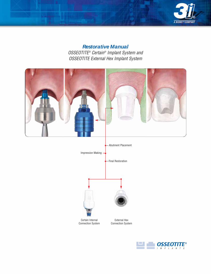
Restorative Manual OSSEOTITE ® Certain ® Implant System and OSSEOTITE External Hex Implant System Abutment Placement Impression Making Final Restoration Certain Internal Connection System External Hex Connection System
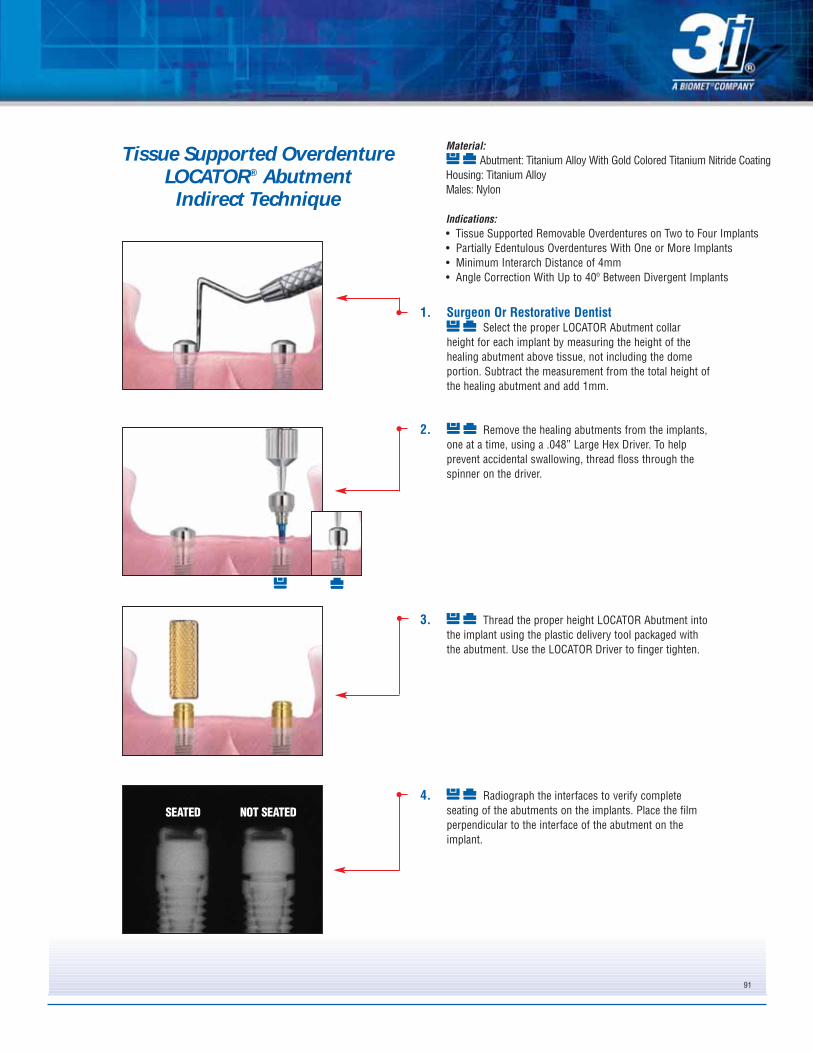
Transcript
Restorative ManualOSSEOTITE® Certain® Implant System andOSSEOTITE External Hex Implant System
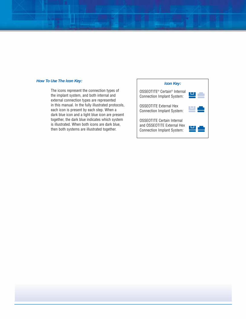
OSSEOTITE Certain Internal and OSSEOTITE External HexConnection Implant System:
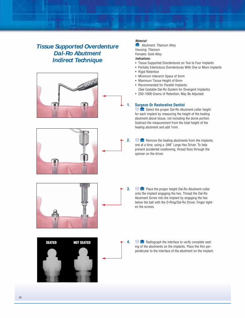
How To Use The Icon Key:
The icons represent the connection types of the implant system, and both internal and external connection types are represented in this manual. In the fully illustrated protocols, each icon is present by each step. When a dark blue icon and a light blue icon are present together, the dark blue indicates which systemis illustrated. When both icons are dark blue, then both systems are illustrated together.
Bar Supported OverdentureStandard Abutment Hader Bar .....................................................................................................................Page 74UCLA Abutment Hader Bar ..........................................................................................................................Page 85
3i's unique implant and restorative component designs pro-
vide practitioners with a wide range of restorative options,
including support for single tooth crowns, fixed and remov-
able prostheses and attachments for securing overdentures.
3i's implant and abutment systems utilize proven restorative
designs and provide clinicians and patients with predictable
treatment options.
General InformationThis manual provides instruction for restorative
practitioners in the use of 3i's restorative systems.
The success of any dental implant system depends
upon proper use of the components and instrumentation. This
manual is not intended for use as a substitute for
professional training and experience.
3
Treatment Planning
Treatment PlanningPatient Evaluation And SelectionSeveral important factors must be considered when
evaluating a patient prior to implant surgery. The
presurgical evaluation must include a careful and detailed
assessment of the patient’s general health, medical
history, oral hygiene, motivation and expectations. If the
patient’s medical history reveals an existing condition
or signals a potential problem that may compromise
treatment and/or the patient’s well being, consultation with a
physician is recommended. In addition, the clinician should
determine if the patient presents with an acceptable anatomi-
cal foundation that is conducive to implant placement. An
extensive intraoral examination should be performed to evalu-
ate the oral cavity for any potential bone or soft-tissue pathol-
ogy. The clinician should also determine the periodontal sta-
tus of the remaining teeth, the health of the soft tissue, the
presence of occlusal abnormalities or parafunctional habits,
such as bruxism or crossbite and any other conditions that
could adversely affect the restorative outcome.
Pre-Operative PlanningProper treatment planning includes selection of
appropriate implant lengths, diameters and locations. The
number of implants is a fundamental consideration
for the long-term success of an implant supported restoration.
Before an implant is placed, the anatomical foundation of the
treatment area must be carefully assessed.
During the presurgical restorative planning phase,
it is important for the surgeon, restorative dentist and
laboratory technician to participate in determining the type of
prosthesis and restorative components that will be used.
Such decision making is critical for determining the location
of implants and should be finalized prior to implant surgery.
A top-down treatment planning approach is recommended,
whereby the final prosthesis is designed, implant locations
determined and restorative components selected prior to initi-
ating implant surgery.
Clinical information necessary for determining appropriate
treatment options includes but is not limited to:
determining vertical dimension, evaluating the space
available between the alveolar crest and the opposing
dentition to confirm that available space exists to accommo-
date the proposed abutment and final restoration, locating the
position of important anatomic structures and determining
bone dimensions where implants are to be placed. The height
required by the restorative components varies with the type
of abutment. Therefore, the surgeon and restorative dentist
should carefully evaluate abutment dimensions. Diagnostic
casts should be used pre-operatively to evaluate the residual
ridge and to determine the position and angulation of all
implants. These casts allow the clinician to evaluate the
opposing dentition and its effect on implant position. A surgi-
cal guide is helpful in determining the precise intraoral posi-
tion and angulation of the implants and should be included in
the pre-operative treatment plan.
By visualizing the final design of the prosthesis prior to implant
surgery, both restorative and surgical clinicians have the oppor-
tunity to identify potential restorative problems. They can then
make the necessary modifications to implant selection, location
and the overall treatment plan prior to actually placing the
implants, thus improving treatment predictability and success.
4
Implant System Distinctions
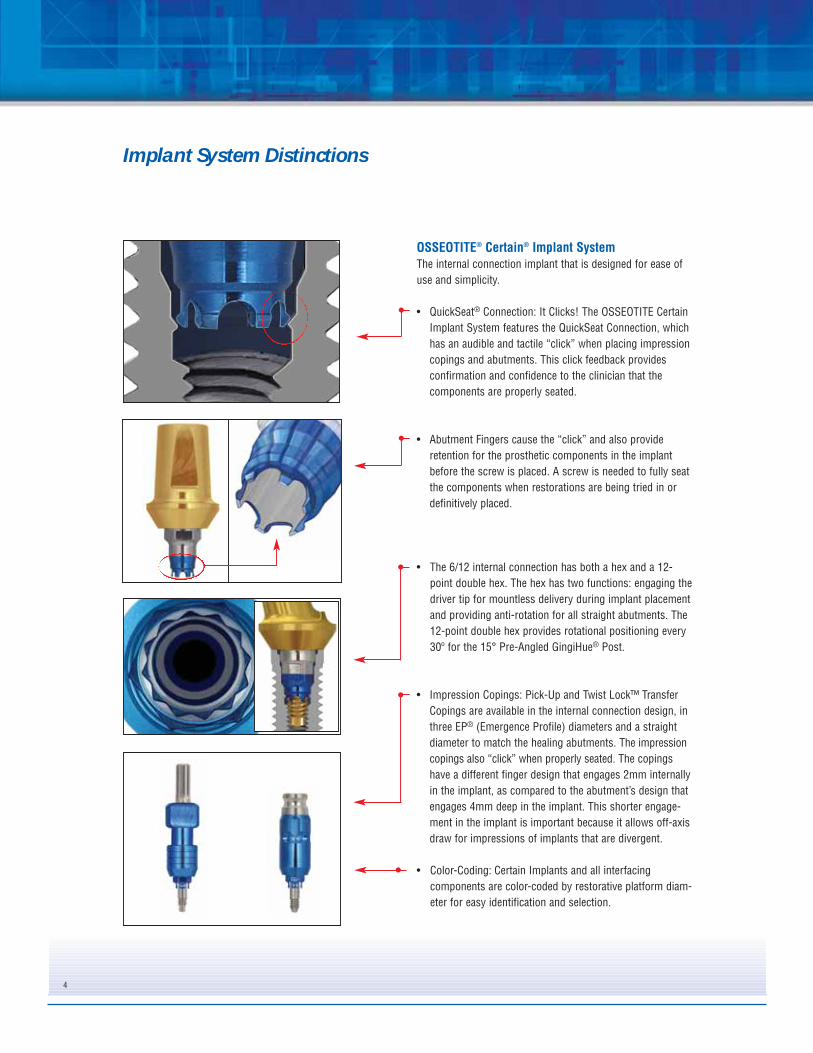
OSSEOTITE® Certain® Implant SystemThe internal connection implant that is designed for ease of
use and simplicity.
• QuickSeat® Connection: It Clicks! The OSSEOTITE Certain
Implant System features the QuickSeat Connection, which
has an audible and tactile “click” when placing impression
copings and abutments. This click feedback provides
confirmation and confidence to the clinician that the
components are properly seated.
• Abutment Fingers cause the “click” and also provide
retention for the prosthetic components in the implant
before the screw is placed. A screw is needed to fully seat
the components when restorations are being tried in or
definitively placed.
• The 6/12 internal connection has both a hex and a 12-
point double hex. The hex has two functions: engaging the
driver tip for mountless delivery during implant placement
and providing anti-rotation for all straight abutments. The
12-point double hex provides rotational positioning every
30º for the 15° Pre-Angled GingiHue® Post.
• Impression Copings: Pick-Up and Twist Lock™ Transfer
Copings are available in the internal connection design, in
three EP® (Emergence Profile) diameters and a straight
diameter to match the healing abutments. The impression
copings also “click” when properly seated. The copings
have a different finger design that engages 2mm internally
in the implant, as compared to the abutment’s design that
engages 4mm deep in the implant. This shorter engage-
ment in the implant is important because it allows off-axis
draw for impressions of implants that are divergent.
• Color-Coding: Certain Implants and all interfacing
components are color-coded by restorative platform diam-
eter for easy identification and selection.
5
OSSEOTITE® External Hex Implant SystemThe external hexed implant design has historically been the
most widely used implant design in implant dentistry.
• Gold Standard ZR™ (Zero Rotation) is a patented design of
machined microstops within the corners of the hex in the
abutment. The design reduces horizontal rotation between
the implant and abutment. Gold Standard ZR is available
on UCLA, GingiHue® Post and Conical abutments.
• The 12-point double hex, which is machined in the 15º
Pre-Angled GingiHue Post, provides rotational positioning
in 30º increments on the implant hex.
• Impression Copings: Pick-Up and Twist Lock™ Transfer
Copings are both available in the external hex design, in
three EP® (Emergence Profile) diameters and a straight
diameter to match the healing abutments. The patented
Twist Lock design provides a more accurate transfer of the
implant hex compared to other transfer (closed tray) tech-
niques. The unique Twist Lock feature provides a series of
undercuts to guide the coping into the impression for sta-
bility. As a result, the copings lock into orientation grooves
upon clockwise rotation, thereby allowing a tactile sensa-
tion of resistance that ensures an accurate hex transfer.
• Precise Abutment Placement: The ASYST® Abutment
Placement Tool provides fingertip control for fast and easy
abutment delivery. The patented packaging design makes
abutment placement easier because the abutment is deliv-
ered sterile from the package directly to the implant site.
The abutment and abutment screw are packaged inside the
plastic ASYST seating device. The plastic seating device
facilitates precise placement of the abutment on the
implant, thus reducing chair time. The ASYST Tool is
packaged with Standard and Conical abutments.
6
Certain® QuickSeat® Activator Tool
The QuickSeat Activator Tool is used to verify that thefingers on the impression copings and abutments are inthe proper position to ensure the click when placed intothe implant (fig. 1). The QuickSeat Activator Tool ismarked to indicate the areas to activate the impressioncopings on one end and the abutments on the opposite end.
To activate the QuickSeat Fingers, locate the proper endfor the component.
• Impression Copings: Insert the impression coping onto the pin, fingers first and slide inward until the fingers meet the tool (fig. 2).
• Abutments: Insert the abutment onto the pin,fingers first and slide inward until the platform meets the tool (fig. 3).
Remove the component from the pin and insert it intothe implant.
In addition, there is an area indicated on the tool for deactivating the fingers on a Hexed UCLA Abutment (fig. 4). This may be necessary when laboratorytechnicians prefer to insert and remove the abutmentfrom the analog without the finger retention duringwaxing, finishing or porcelain application. After thecustom abutment or crown is completed, the UCLAfingers must be reactivated (fig. 5).
UCLA Abutment QuickSeat Deactivation
Impression Coping QuickSeat Activation
UCLA Abutment QuickSeat Activation
GingiHue® Post and ConicalAbutment Fingers
Impression Coping Fingers
fig. 1
fig. 2
Abutment QuickSeat Activation
fig. 4
fig. 5
fig. 3
7
Certain® Hexed And Non-Hexed Pick-UpImpression Coping Draw Angles
Maximum Draw Of Certain Hexed Pick-UpImpression Copings
The Certain Hexed Pick-Up Impression Copings are designed with a shallowinternal connection and a draft on the hex, which allows these to draw fromimplants placed at divergent angles to a maximum of 30º per implant. Thismaximum angulation is possible with individual or multiple copings that arenot rigidly splinted together before the impression is made (fig. 6).
Maximum Draw Of Certain Hexed Pick-UpImpression Copings And Non-Hexed Pick-UpImpression Copings When Rigidly SplintedTogether
Clinicians may desire to rigidly splint the Pick-Up Impression Copings togetherprior to impressioning a multi-implant, implant level restoration. The HexedPick-Up Impression Copings will not draw from multiple divergent implantswhen rigidly splinted together. This impression technique may only be usedon parallel implants (fig. 7).
The Non-Hexed Pick-Up Impression Copings have a maximum draw angle of40º between implants and will draw when rigidly splinted together as impres-sion copings. The Non-Hexed Pick-Up Impression Copings have a shallownon-hex engaging internal connection that allows up to 40º of draw (fig. 8)
When clinicians desire to splint the impression copings together before making an impression of multiple divergent implants for a splinted implantrestoration, the Non-Hexed Pick-Up Impression Copings may be used inplace of the Hexed Pick-Up Impression Copings (fig. 9).
The OSSEOTITE® Certain Line of restorative components includes a newly designed UCLA Abutment. This new designprovides greater predictability and more flexibility for laboratorytechnicians when waxing and casting implant level restorations.
• Improved Cylinder Retention DesignThe new design incorporates machined vertical grooves that reduces the potential for miscasts due to the smoother alloyflow onto the gold alloy cylinder during casting. The verticalgrooves provide mechanical retention and are designed toeliminate the problem on previous UCLA designs of the alloystopping on the horizontal retention instead of flowing to themargin (fig. 10).
• Chamfer MarginThe chamfer margin design provides a smooth transition from the gold alloy cylinder to the cast alloy at the junction. It also aids in the prevention of alloy flowing onto the interface area of the gold alloy cylinder during casting (fig. 10).
• Reduced Collar HeightThe collar height has been reduced from 1mm to 0.25mm to provide greater flexibility when fabricating restorations for implants with shallow tissue depths. This allows the restorationto emerge from the implant platform more quickly and to add porcelain closer to the implant platform on screw retainedrestorations (fig. 11).
• Collar Adjustment After CastingThe reduced collar height may cause an undercut laterallyaround the implant platform. The undercut should beremoved after casting by tapering the collar back (fig. 12).
fig. 10
fig. 11
fig. 12
Certain UCLAScrew Retained
CrownCrown CopingCertain UCLACement Retained
CrownCustom Abutment
9
Large Diameter Gold-Tite Abutment Screw
Internal Engagement
fig. 13 Certain Non-Hexed UCLA Abutment
4mm
1mm
fig. 1440º Divergence Between Splinted Implants
The Certain Non-hexed Abutments are designed to provide flexibility forlaboratory technicians when fabricating splinted multi-unit, screw-retained provisionals, bridge frameworks and bars for implant levelrestorations.
• Internal EngagementThe non-hexed abutments have a 1mm internal engagementfeature to allow a greater degree of draw from multiple divergent implants than other internal connection implant systems (fig. 13).
• Large Diameter Abutment ScrewThe non-hexed abutments are retained into the implant with aunique Large Diameter Gold-Tite® or Titanium Abutment Screw. Thelarger diameter screw provides lateral stability to the restoration. Itgoes into the full depth of the internal connection, replacing the4mm length of the hexed abutment’s connection (fig. 13). EachCertain Non-hexed Abutment is packaged with a Large DiameterGold-Tite or Titanium Abutment Screw.
• Maximum Draw Of Non-Hexed Abutments The non-hexed abutments have a maximum draw angle of 40ºbetween implants (fig. 14).
• Gold Alloy Cylinder FormulationThe formulation specifics for the gold alloy cylinder material used with the UCLA Abutments is indicated on the chart to theright. The formulation should be taken into consideration during burnout and casting procedures.
Melting Range 1400-1490º C (2550-2710º F)
Solidus 1400º C
Liquidus 1490º C
CTE 13.5 x 10⁻⁶ ºK at 500º C
GOLD ALLOY CYLINDER FORMULATION
An alloy with a CTE of 14.5 x 10⁻⁶ ºK at 500º C is recommended
Certain® Non-Hexed Abutments
ChoicesPick-Up Impression CopingThe Pick-Up Impression Coping transfers the position of an implant hex to a laboratory cast. The coping is picked up inside the impression when the impression is removed from the mouth. An open top impression tray is used with the Pick-Up Impression Coping.
Note• Pick-Up Impression Copings may be difficult to use in limited, interarch distance spaces.• Pick-Up Impression Copings are ideal for use when an impression is made of multiple divergent implants.
Twist Lock™ Transfer CopingThe Twist Lock Transfer Coping transfers the position of an implant hex to the laboratory cast. The coping is designed to stay on the implant in the mouth when the impression is removed. The coping is then removed from the implant and transferred into the impression. A closed top impression tray is used with the Twist Lock Transfer Coping.
Note• Twist Lock Impression Copings are ideal for use in limited, interarch distance spaces.• Twist Lock Impression Copings are contraindicated for use when an impression is made of multiple divergent
implants. There is a risk of not being able to remove the impression tray from the copings once the impression material has set.
Selecting The Proper Impression CopingSelect the proper platform diameter Pick-Up or Twist Lock Transfer Impression Coping(s) by matching the color of the implant platform(s). Also, match the diameter of the coping to the EP® Diameter of the healing abutment. See healing abutment measurements:
If using the Pick-Up Impression Coping, turn to page 11.If using the Twist Lock Transfer Impression Coping, turn to page 14.
Components Needed• Matching Platform and EP Diameter Pick-Up or Twist Lock Impression Coping(s).• Matching implant laboratory analog(s).
Instruments Needed• PHD02N or PHD03N - .048in. Large Hex Driver• ICD00 - Impression Coping Driver (For Twist Lock Only).
10
Implant Level Impressions
EP (Emergence Profile)Height
Restorative Platform
Healing Abutment Measurements:
11
1. Restorative DentistSelect the proper Pick-Up Impression Coping by
matching the EP® Diameter of the healing abutment andmatching the color of the implant platform to determineplatform diameter (see below). Remove the healingabutment from the implant using the Large Hex Driver. Tohelp prevent accidental swallowing, thread floss throughthe spinner on the driver.
2. Activate the fingers using the QuickSeat® ActivatorTool. Place the Pick-Up Impression Coping into theimplant, line up the hex and press firmly until feeling thetactile click.
or
Place the Pick-Up Impression Coping on theimplant and engage the hex.
Thread the Pick-Up Impression Coping Screw intothe implant until finger tight. Tighten the screw using theLarge Hex Driver.
3. Radiograph the interface to verify complete seatingof the coping on the implant. Place the film perpendicularto the interface of the coping on the implant or abutment.
4. A custom or stock open top impression tray isused for the Pick-Up Impression Technique. Cut a smallhole in the tray through which the screw may protrude.Try in the tray to verify that the screw head is visiblethrough the opening.
Implant And Abutment Level ImpressionsPick-Up Impression Copings
SEATED NOT SEATED
(Certain® Illustrated)
3.4mm 4.1mm 5mm 6mm
(purple) (blue) (yellow) (green)
12
5. A medium or heavy body impression material isrecommended. Syringe impression material aroundthe entire Pick-Up Impression Coping.
6. Load the impression tray and seat in the mouth.Wipe impression material off the top of the screw before itsets. Allow the impression material to set per the manu-facturer’s instructions.
7. After the impression material has set, remove thePick-Up Impression Coping Screw using the Large HexDriver. Remove the impression from the mouth.
8. Verify that the impression material completelyadapted around the coping.
Implant And Abutment Level ImpressionsPick-Up Impression Copings
13
9. Immediately replace the healing abutment on theimplant using the Large Hex Driver.
10. LaboratoryPlace the proper diameter Implant Lab Analog
onto the impression coping, engaging the hex. Hold theanalog in place while tightening the screw with the LargeHex Driver. Verify that the impression coping is seatedpassively on the analog.
11. Syringe a soft-tissue material around the copingand analog interface. Pour the cast in die stone. Articulatewith opposing cast.
Implant And Abutment Level ImpressionsPick-Up Impression Copings
14
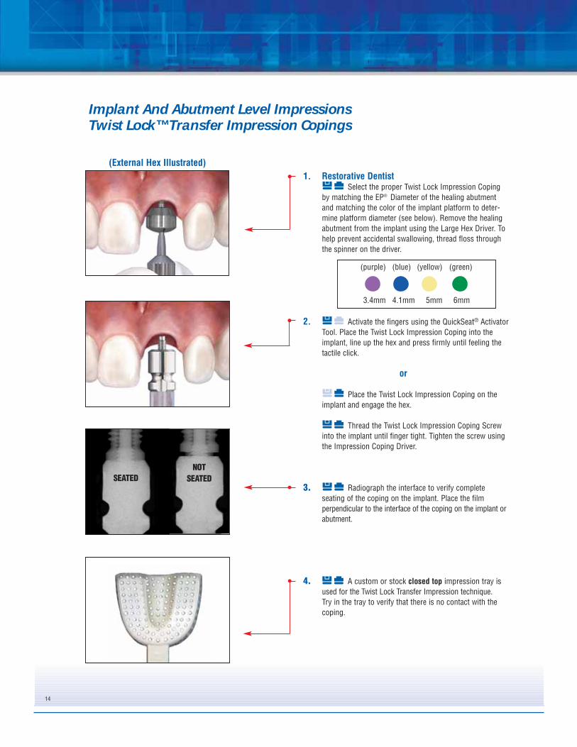
1. Restorative DentistSelect the proper Twist Lock Impression Coping
by matching the EP® Diameter of the healing abutmentand matching the color of the implant platform to deter-mine platform diameter (see below). Remove the healingabutment from the implant using the Large Hex Driver. Tohelp prevent accidental swallowing, thread floss throughthe spinner on the driver.
2. Activate the fingers using the QuickSeat® ActivatorTool. Place the Twist Lock Impression Coping into theimplant, line up the hex and press firmly until feeling thetactile click.
or
Place the Twist Lock Impression Coping on theimplant and engage the hex.
Thread the Twist Lock Impression Coping Screwinto the implant until finger tight. Tighten the screw usingthe Impression Coping Driver.
3. Radiograph the interface to verify completeseating of the coping on the implant. Place the filmperpendicular to the interface of the coping on the implant orabutment.
4. A custom or stock closed top impression tray isused for the Twist Lock Transfer Impression technique. Try in the tray to verify that there is no contact with thecoping.
Implant And Abutment Level ImpressionsTwist Lock™ Transfer Impression Copings
SEATED
NOT
SEATED
(External Hex Illustrated)
3.4mm 4.1mm 5mm 6mm
(purple) (blue) (yellow) (green)
15
5. A medium or heavy body impression material isrecommended. Syringe impression material around theentire Twist Lock Impression Coping.
6. Load the impression tray and seat in the mouth.Allow the impression material to set per the manufactur-er’s instructions.
7. After the impression material has set, remove theimpression from the mouth. The Twist Lock ImpressionCoping will remain on the implant. Verify that the impres-sion material completely adapted around the coping.
8. Remove the Twist Lock Coping from the implantusing the Impression Coping Driver.
Implant And Abutment Level ImpressionsTwist Lock™ Transfer Impression Copings
16
9. Immediately replace the healing abutment on theimplant using the Large Hex Driver.
10. LaboratoryPlace the proper diameter Implant Lab Analog into
the impression coping engaging the hex. Hold the compo-nents together while finger tightening the screw. Verifythat the impression coping is seated passively on the ana-log.
11. Re-index the impression coping/analog assemblyinto the impression using firm pressure to its full depth.Slightly rotate the coping/analog clockwise until feelingantirotational resistance. This indicates that the orientationgrooves are locked into place and the implant hex is accu-rately transferred.
12. Syringe a soft-tissue material around the copingand analog interface. Pour the cast in die stone. Articulatewith the opposing cast.
Implant And Abutment Level ImpressionsTwist Lock™ Transfer Impression Copings
17
Prosthetic Abutment Selection Guide
1. Restorative DentistNote the size of the implant platform and the EP®
Diameter from the healing abutment to select the propersize Prep-Tite Abutment. The implant platform diameter isalso identified by the color code anodized on the implantsand components. See below.
2. Select the proper abutment collar height by meas-uring the height of the healing abutment above tissue,NOT including the dome portion. Subtract the measure-ment from the total height of the healing abutment.
3. Using a .048” Large Hex Driver, evaluate angulationby inserting the driver into the healing abutment hex. If theangle appears to be more than 10º, use the ProstheticAngle Guide Kit to determine the approximate angulationof the implant. The Prosthetic Angle Guide Kit consists of15, 25 and 35 degree pins in 2, 4 and 6mm collar heights.
4. Place the pins into the implant to select the properangled abutment. The correct angle will have the guide pinin line with the central fossa of the adjacent posterior teethor the incisal line angle of the adjacent anterior teeth.
EP (Emergence Profile)
Restorative PlatformHeight
3.4mm 4.1mm 5mm 6mm
(purple) (blue) (yellow) (green)
18
Restorative Products Flow Chart
Is The Implant Angled?(Greater than 15º Divergence)
Interarch Space
UCLA15º Pre-Angled GingiHue
Encode
YesNo
Is The Implant Angled?(Greater than 15º Divergence) YesNo
Less than 7mmUCLA
EncodeProvide
Less than 2mmUCLA
ProvideEncode
7mm or more
Tissue Height
Less than 2mmUCLA
ProvideEncode
2mm or moreGingiHue
UCLAEncodeZiReal
ProvideEncode
Interarch Space
Less than 7mmUCLA
Encode
7mm or moreUCLA
15º Pre-Angled GingiHueEncode
Tissue Height
Less than 2mmUCLA
Encode
2mm or moreUCLA
15º Pre-Angled GingiHueEncode
Is the implant centered in the tooth site?If the answer is no, UCLA is the best option.
Interarch Space
UCLAConical
IOL®
Less than 5mmUCLAIOL
5mm or moreUCLA
Conical
Less than 2mmUCLA
2mm or moreUCLAIOL
Interarch Space
Less than 9.5mmUCLAIOL
9.5mm or more17º Angled Conical25º Angled Conical
Tissue Height
Less than 2mmUCLA
2mm or more17º Angled Conical25º Angled Conical
Is the implant centered in the tooth site? If the answer is no, UCLA is the best option.
Less than 2mmUCLA
2mm or moreUCLA
Conical
GingiHue®
UCLAZiReal®
Encode®
Provide®
UCLA17º Angled Conical25º Angled Conical
IOL
GingiHueUCLA
ZiRealEncodeProvide
Cement-Retained Restoration Details
Screw-Retained Restoration Details
Tissue Height Tissue Height
Tissue Height
19
AbutmentsIPA4155IPA4255IPA4355IPA4455
IPA5140IPA5240IPA5340IPA5440
IPA6140IPA6240IPA6340IPA6440
IPA5155IPA5255IPA5355IPA5455
IPA6155IPA6255IPA6355IPA6455
IPA4140IPA4240IPA4340IPA4440
IUNIHG IUNIHG IUNIHGIUNIHG
PPC485 PPC654 PPC655PPC484
PIC485Non-Prepared
PIC485HPrepared
PIC654Non-Prepared
PIC654HPrepared
PIC655Non-Prepared
PIC655HPrepared
PIC484Non-Prepared
PIC484HPrepared
LaboratoryAnalogs
PAA485Non-Prepared
PAAP485Prepared
PAA654Non-Prepared
PAAP654Prepared
PAA655Non-Prepared
PAAP655Prepared
PAA484Non-Prepared
PAAP484Prepared
WaxingSleeves
PWS48SSingle Unit
PWS48MMulti-Unit
PWS65SSingle Unit
PWS65MMulti-Unit
PWS65SSingle Unit
PWS65MMulti-Unit
PWS48SSingle Unit
PWS48MMulti-Unit
Screws
ProtectionCaps
ImpressionCopings
a = 4.1mmc = 4mmd = 4.8mm
a = 4.1mmc = 5.5mmd = 4.8mm
a = 5mmc = 4mmd = 6.5mm
a = 6mmc = 4mmd = 6.5mm
a = 5mmc = 5.5mmd = 6.5mm
a = 6mmc = 5.5mmd = 6.5mm
Blue Yellow Green Yellow Green
* b: collar height selection depends on tissue depth
Blue
TemporaryCylinders
PUA48SSingle Unit
PUA48MMulti-Unit
PUA65SSingle Unit
PUA65MMulti-Unit
PUA65SSingle Unit
PUA65MMulti-Unit
PUA48SSingle Unit
PUA48MMulti-Unit
Provide® Abutment Selection guide
20
Provide® Abutment Selection
1. Select the proper abutment collar height bymeasuring the height of the healing abutment above thetissue on the buccal, not including the dome portion.Subtract this measurement from the total height of thehealing abutment, then subtract an additional 1mm. Theresulting abutment collar height will place the crownmargin 1mm subgingival on the buccal. Next, select theproper post height that will allow approximately 2mm ofinterarch distance space between the top of the post andthe opposing occlusion. Finally, match the color of theimplant platform to determine the platform diameter.
2. Remove the healing abutment using a .048" Large HexDriver. To help prevent accidental swallowing, threadfloss through the spinner on the driver.
3. Activate the fingers on the Provide Abutment using theQuickSeat® Activator Tool.
4.1mm 6mm5mm
Material: Titanium Alloy
Indications:
• Single- and Multi-Unit Porcelain Fused to Metal Restorations• Maximum Angulation Correction of 10°• Minimum Interarch Space of 6mm
21
4. Place the Provide Abutment into the implant. Line upthe hexes and place the flat side of the post to the buc-cal. Press firmly until hearing and feeling the audibleand tactile click.
5. Thread the Certain® Gold-Tite® Abutment Screw intothe implant until finger tight using a .048" Large HexDriver. Radiograph the interface to verify an accuratefit. Torque the abutment screw to 20Ncm using a .048"Large Hex Driver Tip and a torque device. Seal the topof the access hole with temporary filling material.
In many cases, with proper abutment selectionand ideal angulation, preparation of the abut-ment post will not be necessary. The following isthe restorative procedure for a non-preparedProvide Abutment.
Impression Procedure6. Place the appropriate Provide Impression Coping over
the Provide Abutment making sure that the flat side ofthe impression coping mates with the flat side of theabutment. Snap the impression coping over theabutment margin area.
7. Syringe a medium-to-heavy body impression materialaround the Provide Impression Coping, load theimpression tray and seat in the mouth. Allow theimpression material to set per the manufacturer’sinstructions. Remove the impression from the mouth.The impression coping will be picked-up in theimpression.
8. Send the impression to the laboratory with an opposingcast or impression and a bite registration.
Please Note: Provide Impression and Restorative Components are not compatible with the Straumann-ITI® Implant System.
23
Provisionalization Procedure9a. Place the appropriate Provide Protection Cap over the
abutment and press firmly to snap it over the abutmentmargin area.
or
9b. Fabricate a provisional crown utilizing a ProvideTemporary Cylinder. Place a small amount of temporarycement inside the Provide Temporary Cylinder to ensurethat the fit remains passive on the Provide Abutmentmargin during fabrication of the provisional crown.
For a single-unit provisional crown, line up the anti-rotational flat side of the Provide Temporary Cylinderwith the anti-rotational flat side of the ProvideAbutment. For multiple unit provisionals, there is noanti-rotational flat to align.
Masticatory forces and lengths of the multiple-unitspans should be evaluated and the addition of areinforcement material may be required.
Once the Provide Temporary Cylinder is secure on theProvide Abutment, try in and adjust the fit of aprefabricated crown shell over the cylinder. Reduce theheight of the cylinder as needed. Add acrylic resin orcomposite material inside the prefabricated crown shelland into the retention facets of the Provide TemporaryCylinder and allow it to set per the manufacturer’sinstructions. Check contacts and adjust the occlusion.
Remove the provisional crown with the ProvideTemporary Cylinder joined to it from the abutment.Remove any temporary tacking cement from the insideof the provisional crown and Provide Abutment. Fill inany voids, finish the crown to the desired contour andpolish. Attach the crown to the Provide Abutment withtemporary cement and allow it to set per themanufacturer’s instructions.
Laboratory Procedure10. Use the appropriate, color-coded Provide Analog that
matches the impression coping. Line up the flat side ofthe analog post with the flat in the impression coping.Then, insert the Provide Analog into the ProvideImpression Coping until it snaps over the margin. Pourthe cast in stone using a soft tissue material around theanalog. Articulate with the opposing cast.
11. Block out the dimple on the top of the ProvideAbutment Analog with wax prior to waxing the crowncoping on the Provide Waxing Sleeve. Use thecorresponding sized waxing sleeve to fabricate the finalPFM crown coping. Place the waxing sleeve over thepost, line up the flat sides and verify it is seated to themargin. Tack the sleeve in position with wax.
12. Wax the single unit PFM crown coping to the waxingsleeve. Invest, burnout and cast the coping in a semi-precious or high noble alloy.
13. Opaque, build porcelain, stain and glaze the crown.
Delivery Of Restoration14. Remove the Provide Protection Cap or provisional
crown from the abutment using cotton pliers. Try thecrown on the Provide Abutment and check occlusion,marginal fit and interproximal contacts. Cement thecrown onto the abutment.
Prepared PostSome circumstances will require the clinician toprepare the Provide Abutment Post. The followingis the restorative procedure for preparing aProvide Abutment Post and the associatedimpression making and laboratory procedures.
See Steps 1-5 on pages 19 and 20 for Provide Abutmentselection and placement.
Post Preparation6. When reducing a Provide Abutment Post, a carbide bur
with copious irrigation is recommended. Prepare theabutment post, leaving 2mm of interarch space for thealloy and porcelain of the final crown. Do not preparethe margin area of the abutment as this will impactthe fit of interfacing components. Adjustments shouldbe limited to post height.
7. Seal the top of the access hole with temporary fillingmaterial. Snap the appropriate Provide ImpressionCoping With Holes over the abutment margin area.
Impression Procedure8. Inject a medium body impression material around the
Provide Abutment and into both of the large openings atthe sides of the Impression Coping With Holes, causingthe flow of impression material to the margin area,without any voids or bubbles. Impression materialshould be injected until it can be observed extrudingfrom the four small holes at the top surface of theImpression Coping With Holes. Load a full archimpression tray with impression material and seat inthe mouth. Allow the impression material to set per themanufacturer’s instructions.
Please Note: Provide Impression and Restorative Components are not compatible with the Straumann-ITI® Implant System.
9. Remove the impression from the mouth. TheImpression Coping With Holes will be picked up in theimpression. Verify the marginal integrity of theimpression.
Provisionalization Procedure10a. Place the appropriate Provide Protection Cap over the
abutment and press firmly to snap it over the abutmentmargin area.
or
10b. Fabricate a provisional crown utilizing a ProvideTemporary Cylinder. Place a small amount of temporarycement inside the Provide Temporary Cylinder to ensurethat the fit remains passive on the Provide Abutmentmargin during fabrication of the provisional crown.
For a single-unit provisional crown, line up the anti-rotational flat side of the Provide Temporary Cylinderwith the anti-rotational flat side of the ProvideAbutment. For multiple-unit provisionals, there is noanti-rotational flat to align.
Masticatory forces and lengths of the multiple-unitspans should be evaluated and the addition of areinforcement material may be required.
Once the Provide Temporary Cylinder is secure on the Provide Abutment, try in and adjust the fit of aprefabricated crown shell over the cylinder. Reducethe height of the cylinder as needed. Add acrylic resinor composite material inside the prefabricated crownshell and into the retention facets of the ProvideTemporary Cylinder and allow it to set per themanufacturer’s instructions. Check contacts andadjust the occlusion.
Remove the provisional crown with the ProvideTemporary Cylinder joined to it from the abutment.Remove any temporary tacking cement from the insideof the provisional crown and Provide Abutment. Fill inany voids, finish the crown to desired contour and pol-ish. Attach the crown to the Provide Abutment withtemporary cement and allow it to set per themanufacturer’s instructions.
Laboratory Procedure11. Insert the appropriate Provide Laboratory Analog with
pin (PAAP48 or PAAP65) collar into the ProvideImpression Coping With Holes and snap over themargin area. Cut the Provide Die Reinforcing Pin to theproper height and try in for height verification. The pinshould have a minimum of 1mm clearance between thetop of the pin and the impression. Pour the cast instone, inserting the Reinforcing Pin into the ProvideAnalog before the stone sets.
12. Pin, section and articulate with the opposing cast.
13. Apply die spacer and wax the single unit PFM crowncoping on the stone die. Invest, burnout and cast thecoping in a semi-precious or high noble alloy. Opaque,build porcelain, stain and glaze the crown.
Pin Analog Analog/Pinassembled
29
Delivery Of Restoration14. Remove the Provide Protection Cap or provisional
crown from the abutment using cotton pliers. Try thefinal crown on the Provide Abutment and checkocclusion, marginal fit and interproximal contacts.Cement the final crown on the abutment.
1. Restorative DentistFollow the steps for Implant Level Impressions on
pages 11-13 for the Pick-Up Technique and pages 14-16for the Twist Lock™ Transfer Technique.
2. LaboratorySelect the PreFormance Post with the desired EP®
Emergence Profile diameter and collar height. Measure theinterproximal tissue heights and select a collar height thatcan be prepared to follow the gingival contour. Match thecolor of the implant platform.
Place the PreFormance Post into the implantanalog, line up the hex and press firmly until hearing andfeeling the audible and tactile click.
or
Place the proper PreFormance Post onto theimplant analog, engaging the hex.
3. Thread the Hexed Titanium Screw into the analoguntil finger tight using a .048” Large Hex Driver. Mark thePreFormance Post with a pencil in areas requiring prepa-ration.
4. Prepare the PreFormance Post in areas marked tothe desired depth using a carbide bur. Refine with a coarsediamond bur. Prepare margins to 1mm subgingival, follow-ing the gingival contours. The post can be prepared on thecast or may be removed and placed on a laboratory abut-ment holder for preparation. Maintain three walls of theabutment and .5mm of wall thickness during preparation.
• Single- and Multiple-Unit Cement Retained Provisional Restorations • Minimum Interarch Space of 6mm • Maximum Angulation of 15 Degrees • Intraoral Use Limited to 180 Days • Immediate Non-Occlusal Loading of Single-Unit Provisional
Restorations • Multiple-Unit Restorations Will Require an Evaluation of Occlusal
Forces in Lateral and Protrusive Excursions and MasticatoryForces to Minimize the Load on the Provisional Restorations.
• Guided Soft Tissue Healing of Single- and Multiple-UnitRestoration of Integrated Implants
31
5. Fabricate the provisional crown on the preparedPreFormance Post using the provisional material ofchoice.
6. Restorative DentistRemove the healing abutment from the implant
using a .048” Large Hex Driver. To help prevent accidentalswallowing, thread floss through the spinner on the driver.
Activate the fingers using the QuickSeat® ActivatorTool. Place the prepared PreFormance Post into the implant,line up the hex and press firmly until hearing and feeling theaudible and tactile click.
or
Place the prepared PreFormance Post onto theimplant, engaging the hex.
Thread the Hexed Titanium Screw into the implantuntil finger tight using a .048 Large Hex Driver.
7. Try the provisional crown on the PreFormancePost and check the marginal fit, interproximal contacts andocclusion.
Remove the provisional crown. Torque the Hexed TitaniumScrew to 20Ncm using a .048” Large Hex Driver Tip and atorque device.
Place a protective material over the screw head. Seal theaccess hole with a temporary filling material. Cement thecrown on the post using a temporary cement. Removeexcess cement.
When using PreFormance Posts in immediate nonocclusalloading protocols for multiple units, please follow theseinstructions:• Do not splint to natural dentition• If splinting to other integrated implants, centric,
lateral and protrusive forces should be out of occlusion.Masticatory forces should be minimized allowing theintegrated implant to absorb the forces.
• If splinting to other immediately placed implants, noocclusion and a soft diet should be recommended to thepatient for six to eight weeks.
1. ClinicianSelect the PreFormance Post with the desired EP®
Emergence Profile diameter and collar height. Measure theinterproximal tissue heights and select a collar height thatcan be prepared to follow the gingival contour. Match thecolor of the implant platform.
Activate the fingers using the QuickSeat® Activator Tool.Place the PreFormance Post into the implant, line up thehex and press firmly until hearing and feeling the audibleand tactile click.
or
Place the PreFormance Post onto the implantengaging the hex.
Thread the Hexed Titanium Screw into the implantuntil finger tight using a .048” Large Hex Driver. To helpprevent accidental swallowing, thread floss through thespinner on the driver. Mark the PreFormance Post with apencil in areas requiring preparation.
2. Prepare the PreFormance Post in areas markedusing a high-speed handpiece, carbide bur and irrigation.Refine with a coarse diamond bur. Prepare margins to1mm subgingival, following the gingival contours. Thepost can be prepared intraorally or removed and placed ona laboratory abutment holder for preparation. Maintain 3walls of the abutment and .5mm of wall thickness duringpreparation.
3. Once abutment preparation is complete, securethe abutment to the implant using the Hexed TitaniumScrew torqued to 20Ncm using a .048” Large Hex DriverTip and a torque device.
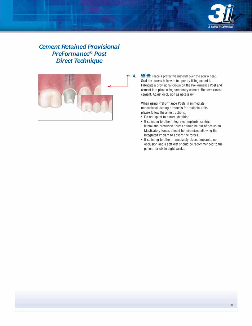
4. Place a protective material over the screw head.Seal the access hole with temporary filling material.Fabricate a provisional crown on the PreFormance Post andcement it to place using temporary cement. Remove excesscement. Adjust occlusion as necessary.
When using PreFormance Posts in immediate nonocclusal loading protocols for multiple-units, please follow these instructions:• Do not splint to natural dentition• If splinting to other integrated implants, centric,
lateral and protrusive forces should be out of occlusion.Masticatory forces should be minimized allowing theintegrated implant to absorb the forces.
• If splinting to other immediately placed implants, noocclusion and a soft diet should be recommended to thepatient for six to eight weeks.
33
Cement Retained Provisional PreFormance® Post
Direct Technique
34
1. Restorative DentistFollow the steps for Implant Level Impressions on
pages 11-13 for the Pick-Up Technique and pages 14-16for the Twist Lock™ Transfer Technique.
2. LaboratorySelect the PreFormance Post with the desired EP®
Emergence Profile diameter and collar height. Measure theinterproximal tissue heights and select a collar height thatcan be prepared to follow the gingival contour. Match thecolor of the implant platform. The post may be rotated in30º increments to ideally position it to correct the implantangulation.
Place the Pre-Angled PreFormance Post onto theimplant analog, line up the hex in the 12-point double hexand press firmly until hearing and feeling the audible andtactile click.
or
Place the proper Pre-Angled PreFormance Postonto the implant analog, engaging the hex.
3. Thread the Hexed Titanium Screw into the analoguntil finger tight using a .048” Large Hex Driver. Mark thePreFormance Post with a pencil in areas requiringpreparation.
4. Prepare the Pre-Angled PreFormance Post using acarbide bur. Refine with a coarse diamond bur. Preparemargins to 1mm subgingival. The post can be prepared onthe cast or may be removed and placed on a laboratoryabutment holder for preparation. Maintain three walls of theabutment and .5mm of wall thickness during preparation.
Cement Retained Provisional 15º Pre-Angled PreFormance® Post
Indirect Technique
Cement Retained Provisional 15º Pre-Angled PreFormance® Post
Indirect Technique
35
5. Fabricate the provisional crown on the preparedPreFormance Post using the provisional material ofchoice.
6. Restorative DentistRemove the healing abutment from the implant
using a .048” Large Hex Driver. To help prevent accidentalswallowing, thread floss through the spinner on the driver.
Activate the fingers using the QuickSeat® ActivatorTool. Place the prepared Pre-Angled PreFormance Postinto the implant, line up the hex in the 12 point double hexand press firmly until hearing and feeling the audible andtactile click.
or
Place the prepared Pre-Angled PreFormance Postonto the implant engaging the hex.
Thread the Hexed Titanium Abutment Screw intothe implant until finger tight using a .048” Large HexDriver.
7. Try the provisional crown on the Pre-AngledPreFormance Post and check the marginal fit, interproximalcontacts and occlusion. Remove the provisional crown.
Torque the Hexed Titanium Screw to 20Ncm using a .048”Large Hex Driver Tip and a torque device. Place aprotective material over the screw head. Seal the accesshole with a temporary filling material. Cement the crown onthe post using a temporary cement. Remove excess cement.
When using PreFormance Posts in immediate nonocclusal loading protocols for multiple-units, please follow these instructions:• Do not splint to natural dentition• If splinting to other integrated implants, centric,
lateral and protrusive forces should be out of occlusion.Masticatory forces should be minimized allowing theintegrated implant to absorb the forces.
• If splinting to other immediately placed implants, noocclusion and a soft diet should be recommended to thepatient for six to eight weeks.
36
Cement Retained Provisional 15º Pre-Angled PreFormance® Post
Direct Technique
1. ClinicianSelect the PreFormance Post with the desired EP®
Emergence Profile diameter and collar height. Measure theinterproximal tissue heights and select a collar height thatcan be prepared to follow the gingival contour. Match thecolor of the implant platform.
Activate the fingers using the QuickSeat® ActivatorTool. Place the Pre-Angled PreFormance Post into theimplant. Line up the hex in the 12-point double hex andpress firmly until hearing and feeling the audible andtactile click. The post may be rotated in 30º increments toideally position it to correct the implant angulation.
or
Place the proper PreFormance Post onto the implant,engaging the hex.
Thread the Hexed Titanium Screw into the implantuntil finger tight using a .048” Large Hex Driver. To helpprevent accidental swallowing, thread floss through thespinner on the driver. Mark the post with a pencil in areasrequiring preparation
2. Prepare the Pre-Angled PreFormance Post inareas marked using a high speed handpiece, carbide burand irrigation. Refine with a coarse diamond bur. Preparemargins to 1mm subgingival. The post can be preparedintraorally or removed and placed on a laboratory abutmentholder for preparation. Maintain three walls of the abutmentand .5mm of wall thickness during preparation.
3. Once abutment preparation is complete, securethe post to the implant using the Hexed Titanium Screwtorqued to 20Ncm using a .048” Large Hex Driver Tip and atorque device.
4. Place a protective material over the screw head.Seal the access hole with temporary filling material. Fabricatea provisional crown on the 15º Pre-Angled PreFormance Postand cement it to place using temporary cement. Removeexcess cement. Adjust occlusion as necessary.
When using PreFormance Posts in immediate nonocclusalloading protocols for multiple-units, please follow theseinstructions:• Do not splint to natural dentition• If splinting to other integrated implants, centric,
lateral and protrusive forces should be out of occlusion.Masticatory forces should be minimized allowing theintegrated implant to absorb the forces.
• If splinting to other immediately placed implants, noocclusion and a soft diet should be recommended to thepatient for six to eight weeks.
37
1. Restorative DentistFollow the steps for Implant Level Impressions on
pages 11-13 for the Pick-Up Technique and pages 14-16for the Twist Lock™ Transfer Technique.
2. LaboratorySet a denture tooth in wax on the cast where the
single tooth is missing.
3. Make a vacuum formed template over the denturetooth and adjacent teeth on the cast. Remove the template,denture tooth and wax from the cast.
4. Select the proper diameter Hexed PreFormanceTemporary Cylinder by matching the color of the implantplatform. Place it into the implant analog, line up the hexand press firmly until hearing and feeling the audible andtactile click. (See page 6 for finger deactivation instruc-tions.)
or
Place the proper diameter Hexed PreFormanceTemporary Cylinder onto the implant analog and engagethe hex.
Thread a waxing screw into the analog until fingertight using a .048” Large Hex Driver.
• Screw Retained Single-Unit Provisional Restorations• Minimum Interarch Space of 4mm• Minimum Tissue Height of 2mm
38
5. Reduce or adjust the cylinder as necessary. Blockout any undercuts apical to the contact points of theadjacent teeth.
6. Cut a hole in the template to accommodate thewaxing screw. Add acrylic resin to the cylinder and tem-plate and place the template on the cast to form the sin-gle-unit provisional crown. Allow the acrylic resin to setper the manufacturer’s instructions. Remove the waxingscrew and template from the cast. Remove the provi-sional crown from the template. Fill in any voids aroundthe subgingival area. Contour and polish the crown.Place the crown back onto the cast and thread a HexedTitanium Screw into the analog until finger tight. Adjustthe occlusion as necessary.
7. Restorative DentistRemove the healing abutment from the implant
using a .048” Large Hex Driver. To help prevent accidentalswallowing, thread floss through the spinner on the driver.
Activate the fingers using the QuickSeat® ActivatorTool. Place the single-unit provisional crown into theimplant, line up the hex and press firmly until hearing andfeeling the audible and tactile click.
or
Place the single unit provisional crown on theimplant, engaging the hex.
Thread a Hexed Titanium Screw into the implantuntil finger tight using a .048” Large Hex Driver. Check theinterproximal contacts. Torque the screw to 20Ncm using a.048” Large Hex Driver Tip and a torque device. Place aprotective material over the screw head. Seal the accesshole with a temporary filling material and composite resin.Make any occlusal adjustments necessary.
1. Restorative DentistFollow the steps for Implant Level Impressions on
pages 11-13 for the Pick-Up Technique and pages 14-16for the Twist Lock™ Transfer Technique.
2. LaboratorySet denture teeth on the cast where the multi-unit
bridge will be fabricated.
3. Make a vacuum formed template over the dentureteeth and adjacent teeth. Remove the template, dentureteeth and wax from the cast.
4. Select and place the proper diameter Non-HexedPreFormance Temporary Cylinders onto the implantanalogs. Thread waxing screws into the analogs untilfinger tight using a .048” Large Hex Driver
• Screw Retained Multi-Unit Provisional Restorations• Minimum Interarch Space of 4mm• Minimum Tissue Height of 2mm• Maximum Divergence of 40º Between Implants
5. Reduce or adjust the cylinders as necessary. Thecylinders may be connected with ortho wire or astrengthening frame may be waxed and cast to support apontic. Block out any undercuts apical to the contactpoints of the adjacent teeth.
6. Cut holes in the template for the waxing screws tocome through. Add acrylic resin to the cylinders andinside the template to form the provisional bridge. Placethe template on the cast. Allow the acrylic to set perthe manufacturer’s instructions. Remove the waxingscrews and the template from the cast. Remove theprovisional bridge from the template. Fill in any voidsaround the subgingival areas. Contour and polish thebridge. Place the bridge back on the cast and threadHexed Titanium Screws into the analogs until fingertight. Adjust the occlusion as necessary.
7. Restorative DentistRemove the healing abutments from the implants
using a .048” Large Hex Driver. To help prevent accidentalswallowing, thread floss through the spinner on the driver.Place the multi-unit provisional bridge onto the implants.Thread Hexed Titanium Screws into the implants until fin-ger tight using a .048” Large Hex Driver.
Check the interproximal and occlusal contacts. Torque thescrews to 20Ncm using a .048” Large Hex Driver Tip anda torque device. Place a protective material over the screwheads. Seal the access holes with temporary fillingmaterial and composite resin. Make any occlusal adjust-ments necessary.
41
Material: Titanium Alloy
Indications:• Screw Retained Single-Unit Provisional Restorations• Minimum Interarch Space of 4mm• Minimum Tissue Height of 2mm
1. Restorative DentistFollow the steps for Implant Level Impressions on
pages 11-13 for the Pick-Up Technique and pages 14-16for the Twist Lock™ Transfer Technique.
2. LaboratorySet a denture tooth in wax on the cast where the
single tooth is missing.
3. Make a vacuum formed template over the denturetooth and adjacent teeth on the cast. Remove the template,denture tooth and wax from the cast.
4. Select the proper diameter Hexed TitaniumTemporary Cylinder by matching the color of the implantplatform. Place it into the implant analog, line up the hex andpress firmly until hearing and feeling the audible and tactileclick. (See page 6 for finger deactivation instructions.)
or
Place the proper diameter Hexed TitaniumTemporary Cylinder onto the analog and engage the hex.
Thread a waxing screw into the analog until fingertight using a .048” Large Hex Driver.
5. Reduce or adjust the cylinder as necessary. Blockout any undercuts apical to the contact points of theadjacent teeth.
6. Cut a hole in the template to accommodate thewaxing screw. Add acrylic resin to the cylinder and templateand place the template on the cast to form the single-unitprovisional crown. Allow the acrylic resin to set per themanufacturer’s instructions. Remove the waxing screw andtemplate from the cast. Remove the provisional crown fromthe template. Fill any voids around the subgingival area.Contour and polish the crown. Place the crown back ontothe cast and thread a Hexed Titanium Screw into the analoguntil finger tight. Adjust occlusion as necessary.
7. Restorative DentistRemove the healing abutment from the implant
using a .048” Large Hex Driver. To help prevent accidentalswallowing, thread floss through the spinner on the driver.
Activate the fingers using the QuickSeat® ActivatorTool. Place the single-unit provisional crown into theimplant, line up the hex and press firmly until hearing andfeeling the audible and tactile click.
or
Place the single unit provisional crown on theimplant, engaging the hex.
Thread a Hexed Titanium Screw into the implantuntil finger tight using a .048” Large Hex Driver.Radiograph the interface to verify an accurate fit. Checkthe interproximal and occlusal contacts. Torque the screwto 20Ncm using a .048” Large Hex Driver Tip and a torquedevice. Place a protective material over the screw head.Seal the access hole with a temporary filling material andcomposite resin. Make any occlusal adjustments necessary.
43
1. Restorative DentistFollow the steps for Implant Level Impressions on
pages 11-13 for the Pick-Up Technique and pages 14-16for the Twist Lock™ Transfer Technique.
2. LaboratorySet denture teeth on the cast where the multi-unit
bridge will be fabricated.
3. Make a vacuum formed template over the dentureteeth and adjacent teeth. Remove the template, dentureteeth and wax from the cast.
4. Select and place the proper diameter Non-HexedTitanium Temporary Cylinders onto the implant analogs.Thread waxing screws into the analogs until finger tightusing a .048” Large Hex Driver.
• Screw Retained Multi-Unit Provisional Restorations• Minimum Interarch Space of 4mm• Minimum Tissue Height of 2mm• Maximum Divergence of 40º Between Implants
44
5. Reduce or adjust the cylinders as necessary Thecylinders may be connected with ortho wire or a strength-ening frame may be waxed and cast to support a pontic.Block out any undercuts apical to the contact points of theadjacent teeth.
6. Cut holes in the template for the waxing screws tocome through. Add acrylic resin to the cylinders andinside the template to form the provisional bridge. Placethe template on the cast. Allow the acrylic to set per themanufacturer’s instructions. Remove the waxing screwsand the template from the cast. Remove the provisionalbridge from the template. Fill in any voids around the sub-gingival areas. Contour and polish the bridge. Place thebridge back on the cast and thread Hexed TitaniumScrews into the analogs until finger tight. Adjust theocclusion as necessary.
7. Restorative DentistRemove the healing abutments from the implants
using a .048” Large Hex Driver. To help prevent accidentalswallowing, thread floss through the spinner on the driver.Place the multi-unit provisional bridge onto the implants.Thread the Hexed Titanium Screws into the implants untilfinger tight using a .048” Large Hex Driver.
Radiograph the interfaces to verify a passive fit. Check theinterproximal and occlusal contacts. Torque the screws to20Ncm using a .048” Large Hex Driver Tip and a torquedevice. Place a protective material over the screw heads.Seal the access holes with temporary filling material andcomposite resin. Make any occlusal adjustments necessary.
1. Restorative DentistFollow the steps for Implant Level Impressions on
pages 11-13 for the Pick-Up Technique and pages 14-16for the Twist Lock™ Transfer Technique.
2. LaboratorySelect the proper GingiHue Post by matching the
EP® Diameter of the healing abutment and matching thecolor of the implant platform.
Place the GingiHue Post into the implant analog,line up the hex and press firmly until hearing and feelingthe audible and tactile click.
or
Place the proper GingiHue Post onto the implantanalog, engaging the hex.
Thread a try-in screw into the analog until fingertight using a .048” Large Hex Driver. Mark the GingiHuePost with a pencil in areas requiring preparation.
3. Prepare the GingiHue Post in areas marked usinga high-speed handpiece and an aggressive carbide bur.Prepare margins 1mm subgingival following the gingivalcontours. The post can be prepared on the cast or may beremoved and placed on a laboratory abutment holder forpreparation.
4. Wax the single unit PFM crown coping on theprepared abutment. Invest, burnout and cast the coping ina semi-precious or high noble alloy. Opaque, build porcelainstain and glaze the crown.
Cement RetainedGingiHue® Post
Indirect Technique
Material:
Titanium Alloy (Certain® Straight Posts and All 15º Pre-Angled Posts)Commercially Pure Titanium (External Hex Straight Posts)
Indications:
• Single- and Multi-Unit Porcelain-Fused-to-Metal Restorations• Areas of Thin Labial Tissue Where Gingival Discoloration is Possible• Maximum Angulation Correction of 15°• Minimum Interarch Space of 6mm
46
5. Restorative DentistRemove the healing abutment from the implant
using a .048” Large Hex Driver. To help prevent accidentalswallowing, thread floss through the spinner on the driver.
Activate the fingers using the QuickSeat® ActivatorTool. Place the prepared GingiHue Post into the implant,line up the hex and press firmly until hearing and feelingthe audible and tactile click. Thread a Certain® Gold-Tite®
Hexed Screw into the implant until finger tight using a.048” Large Hex Driver.
or
Place the prepared GingiHue Post onto theimplant, engaging the hex. Thread a Square Gold-TiteScrew into the implant until finger tight.
Radiograph the interface to verify an accurate fit.
6. Try the single unit PFM crown on the GingiHuePost and check the marginal fit, interproximal contactsand the occlusion.
Torque the Certain Gold-Tite Hexed Screw to 20Ncmusing a .048” Large Hex Driver Tip and a torque device.
or
Torque the Square Gold-Tite Screw to 32-35Ncmusing the Square Driver Tip and a torque device.
Place a protective material over the screw head.Seal the access hole with temporary filling material.Cement the crown on the post using a temporary orpermanent cement.
Cement Retained GingiHue® Post
Indirect Technique
1. Restorative DentistSelect the proper GingiHue Post by matching the
EP® Diameter of the healing abutment and matching thecolor of the implant platform. Remove the healingabutment using a .048” Large Hex Driver. To help preventaccidental swallowing, thread floss through the spinner onthe driver.
Activate the fingers using the QuickSeat® ActivatorTool. Place the GingiHue Post into the implant, line up thehex and press firmly until hearing and feeling the audibleand tactile click.
or
Place the GingiHue Post onto the implant, engag-ing the hex.
Thread a try-in screw into the implant until fingertight using a .048” Large Hex Driver. Radiograph the inter-face to verify an accurate fit. Mark the GingiHue Post witha pencil in areas requiring preparation.
2. Prepare the GingiHue Post in areas marked usinga high-speed handpiece, aggressive carbide bur and irriga-tion. Prepare margins 1mm subgingival following the gin-gival contours. The post can be prepared intraorally orremoved and placed on a laboratory abutment holder forpreparation.
3. Once abutment preparation is complete, replacethe try-in screw with:
the Certain® Gold-Tite® Hexed Screw torqued to20Ncm using a .048” Large Hex Driver Tip and a torquedevice.
or
the Square Gold-Tite Screw torqued to 32-35Ncmusing the Square Driver Tip and a torque device.
4. Place a protective material over the screw head.Seal the access hole with temporary filling material. Placeretraction cord subgingivally to retract the gingiva from themargin prepared on the GingiHue Post. Syringe impressionmaterial around the entire GingiHue Post. Load the impres-sion tray and seat in the mouth. Allow the impression mate-rial to set per the manufacturer’s instructions.
47
Cement RetainedGingiHue® Post
Direct Technique
48
5. Remove the impression. Verify the marginalintegrity of the impression.
6. Fabricate a provisional crown on the GingiHuePost and cement it to place using temporary cement.
7. LaboratoryPour the cast in die stone, pin, section and
articulate with opposing cast.
8. Wax the single-unit PFM crown coping on the die.Invest, burnout and cast the coping in a semi-precious orhigh noble alloy. Opaque, build porcelain, stain and glazethe crown.
Cement RetainedGingiHue® Post
Direct Technique
49
9. Restorative DentistRemove the provisional crown from the GingiHue
Post and remove all cement. Try the single-unit crown onthe post and check the marginal fit, interproximal contactsand the occlusion. Cement the crown on the post using atemporary or permanent cement. Remove excess cement.
Cement RetainedGingiHue® Post
Direct Technique
50
1. Restorative DentistFollow the steps for Implant Level Impressions on
pages 11-13 for the Pick-Up Technique and pages 14-16for the Twist Lock™ Transfer Technique.
2. LaboratorySelect the proper Pre-Angled GingiHue Post by
matching the EP® Diameter of the healing abutment andmatching the color of the implant platform. The post maybe rotated in 30º increments to ideally position it to correctthe implant angulation.
Place the Pre-Angled GingiHue Post into theimplant analog, line up the hex in the 12-point double hexand press firmly until hearing and feeling the audible andtactile click.
or
Place the proper Pre-Angled GingiHue Post ontothe implant analog, engaging the hex.
Thread a try-in screw into the analog until fingertight using a .048” Large Hex Driver. Mark the Pre-AngledGingiHue Post with a pencil in areas requiring preparation.
3. Prepare the Pre-Angled GingiHue Post in areasmarked using a high-speed handpiece and an aggressivecarbide bur. Prepare margins 1mm subgingival followingthe gingival contours. The post can be prepared on thecast or may be removed and placed on a laboratoryabutment holder for preparation.
4. Wax the single-unit PFM crown coping on the pre-pared abutment. Invest, burnout and cast the coping in asemi-precious or high noble alloy. Opaque, build porce-lain, stain and glaze the crown.
Cement Retained15º Pre-Angled GingiHue® Post
Indirect Technique
51
5. Restorative DentistRemove the healing abutment from the implant
using a .048” Large Hex Driver. To help prevent accidentalswallowing, thread floss through the spinner on the driver.
Activate the fingers using the QuickSeat® ActivatorTool. Place the prepared Pre-Angled GingiHue Post intothe implant, line up the hex in the double hex and pressfirmly until hearing and feeling the audible and tactile click.Thread a Certain® Gold-Tite® Hexed Screw into the implantuntil finger tight using a .048” Large Hex Driver.
or
Place the prepared Pre-Angled GingiHue Post ontothe implant, engaging the hex. Thread a Square Gold-Tite Screw into the implant until finger tight using aSquare Driver.
6. Radiograph the interface to verify an accurate fit.Try the single-unit crown on the Pre-Angled GingiHue Postand check the marginal fit, interproximal contacts and theocclusion.
Torque the Certain Gold-Tite Hexed Screw to 20Ncmusing a .048” Large Hex Driver Tip and a torque device.
or
Torque the Square Gold-Tite Screw to 32- 35Ncmusing the Square Driver Tip and a torque device.
Place a protective material over the screw head.Seal the access hole with temporary filling material. Cementthe crown on the post using a temporary or permanentcement. Remove excess cement.
Cement Retained15º Pre-Angled GingiHue® Post
Indirect Technique
52
1. Restorative DentistSelect the proper Pre-Angled GingiHue Post by
matching the EP® Diameter of the healing abutment andmatching the color of the implant platform. The post maybe rotated in 30º increments to ideally position it to correctthe implant angulation. Remove the healing abutment usinga .048” Large Hex Driver. To help prevent accidental swal-lowing, thread floss through the spinner on the driver.
Activate the fingers using the QuickSeat® ActivatorTool. Place the Pre-Angled GingiHue Post into the implant.Line up the hex in the 12-point double hex and press firm-ly until feeling the tactile click.
or
Place the Pre-Angled GingiHue Post onto theimplant, engaging the hex.
Thread a try-in screw into the implant until fingertight using a .048” Large Hex Driver. Radiograph theinterface to verify an accurate fit. Mark the post with apencil in areas requiring preparation.
2. Prepare the Pre-Angled GingiHue Post in areasmarked using a high speed handpiece, aggressive carbidebur and irrigation. Prepare margins 1mm subgingival fol-lowing the gingival contours. The post can be preparedintraorally or removed and placed on a laboratory abutmentholder for preparation.
3. Once abutment preparation is complete, replacethe try-in screw with:
the Certain® Gold-Tite® Hexed Screw torqued to20Ncm using a .048” Large Hex Driver Tip and a torquedevice.
or
the Square Gold-Tite Screw torqued to 32-35Ncmusing the Square Driver Tip and a torque device.
4. Place a protective material over the screw head.Seal the access hole with temporary filling material. Placeretraction cord subgingivally to retract the gingiva fromthe margin prepared on the Pre-Angled GingiHue Post.Syringe impression material around the entire Pre-AngledGingiHue Post. Load the impression tray and seat in themouth. Allow the impression material to set per the manu-facturer’s instructions.
Cement Retained 15º Pre-Angled GingiHue® Post
Direct Technique
53
5. Remove the impression. Verify the marginalintegrity of the impression.
6. Fabricate a provisional crown on the Pre-AngledGingiHue Post and cement it to place using temporarycement.
7. LaboratoryPour the cast in die stone, pin, section and
articulate with opposing cast.
8. Wax the single-unit PFM crown coping on the die.Invest, burnout and cast the coping in a semi-precious orhigh noble alloy. Opaque, build porcelain, stain and glazethe crown.
Cement Retained 15º Pre-Angled GingiHue® Post
Direct Technique
54
9. Restorative DentistRemove the provisional crown from the Pre-
Angled GingiHue Post and remove all cement. Try thesingle-unit PFM crown on the post and check the marginalfit, interproximal contacts and the occlusion. Cement thecrown on the post using a temporary or permanent cement.Remove excess cement.
Cement Retained15º Pre-Angled GingiHue® Post
Direct Technique
55
1. Restorative DentistFollow the steps for Implant Level Impressions on
pages 11-13 for the Pick-Up Technique and pages 14-16for the Twist Lock™ Transfer Technique.
2. LaboratorySelect the proper ZiReal Post by matching the EP®
Diameter of the healing abutment and matching the colorof the implant platform.
Place the ZiReal Post into the implant analog, lineup the hex and press firmly until hearing and feeling theaudible and tactile click. Thread a Certain® ZiReal Try-InScrew into the analog until finger tight using a .048” LargeHex Driver.
or
Place the proper ZiReal Post onto the implantanalog, engaging the hex. Thread a try-in screw into theanalog until finger tight using a .048” Large Hex Driver.
3. Mark the ZiReal Post with a pencil in areas requir-ing preparation.
4. Prepare the ZiReal Post in areas marked using ahigh-speed handpiece and a coarse diamond bur or greenheatless stone. Prepare margins 1mm subgingival, follow-ing the gingival contours. The post can be prepared on thecast or may be removed and placed on a laboratory abut-ment holder for preparation. Maintain 3 walls of the abut-ment and .5mm of wall thickness during preparation.
Cement Retained All CeramicZiReal® Post
Indirect Technique
Material:
Zirconium Oxide With A Fused Titanium Alloy Interface
Indications:
• Single- and Multi-Unit All Ceramic Restorations• Restorations in the Aesthetic Zone• Aesthetic Restorations When Tissue is Limited• Maximum Angulation of 10°• Minimum Interarch Space of 6mm
56
5. Fabricate the all ceramic crown coping on the pre-pared post using the all ceramic system of choice. Buildporcelain on the coping, stain and glaze the single-unitcrown.
6. Restorative DentistRemove the healing abutment from the implant
using a .048” Large Hex Driver. To help prevent accidentalswallowing, thread floss through the spinner on the driver.
Activate the fingers using the QuickSeat® ActivatorTool. Place the prepared ZiReal Post into the implant, lineup the hex and press firmly until hearing and feeling theaudible and tactile click. Thread a Certain® ZiReal Gold-Tite® Hexed Screw into the implant until finger tight usinga .048” Large Hex Driver.
or
Place the prepared ZiReal Post onto the implant,engaging the hex. Thread a Square Gold-Tite Screw intothe implant until finger tight using the Square Driver.
Radiograph the interface to verify an accurate fit.
7. Try the single-unit all ceramic crown on the ZiRealPost and check the marginal fit, interproximal contacts andthe occlusion.
Torque the Certain ZiReal Gold-Tite Hexed Screw to20Ncm using a .048” Large Hex Driver Tip and a torquedevice.
or
Torque the Square Gold-Tite Screw to 32-35Ncmusing the Square Driver Tip and a torque device.
Be sure the driver tip is parallel with the access hole toavoid fracture during torque application.
Place a protective material over the screw head. Sealthe access hole with composite resin. Cement the crown onthe post using a temporary or permanent cement. Removeexcess cement. The ZiReal Post may be etched and thecrown bonded, if preferred.
Cement Retained All CeramicZiReal® Post
Indirect Technique
5757
1. Restorative DentistSelect the proper ZiReal Post by matching the EP®
Diameter of the healing abutment and matching the colorof the implant platform. Remove the healing abutmentusing a .048” Large Hex Driver. To help prevent accidentalswallowing, thread floss through the spinner on the driver.
Activate the fingers using the QuickSeat® ActivatorTool. Place the ZiReal Post into the implant, line up the hexand press firmly until hearing and feeling the audible andtactile click. Thread a Certain® ZiReal Try-In Screw into theimplant until finger tight using a .048” Large Hex Driver.
or
Place the ZiReal Post onto the implant, engagingthe hex. Thread a try-in screw into the implant until fingertight using a .048” Large Hex Driver.
Radiograph the interface to verify an accurate fit.Mark the ZiReal Post with a pencil in areas requiringpreparation.
2. Prepare the ZiReal Post in areas marked using ahigh-speed handpiece, a coarse diamond bur from the ZiRealPost Preparation Kit and irrigation. Prepare margins 1mmsubgingival following the gingival contours. The post can beprepared intraorally or removed and placed on a laboratoryabutment holder for preparation. Maintain 3 walls of the abut-ment and .5mm of wall thickness during preparation.
3. Once abutment preparation is complete, replacethe try-in screw with:
the Certain ZiReal Gold-Tite® Hexed Screwtorqued to 20Ncm using a .048” Large Hex Driver Tip anda torque device.
or
the Square Gold-Tite Screw torqued to 32-35Ncmusing the Square Driver Tip and a torque device.
Be sure the driver tip is parallel with the access holeto avoid fracture during torque application.
4. Place a protective material over the screw head.Seal the access hole with composite resin. Place aretraction cord subgingivally to retract the gingiva from themargin prepared on the ZiReal Post. Syringe impressionmaterial around the entire ZiReal Post. Load the impressiontray and seat in the mouth. Allow the impression material toset per the manufacturer’s instructions.
Cement Retained All CeramicZiReal® Post
Direct Technique
58
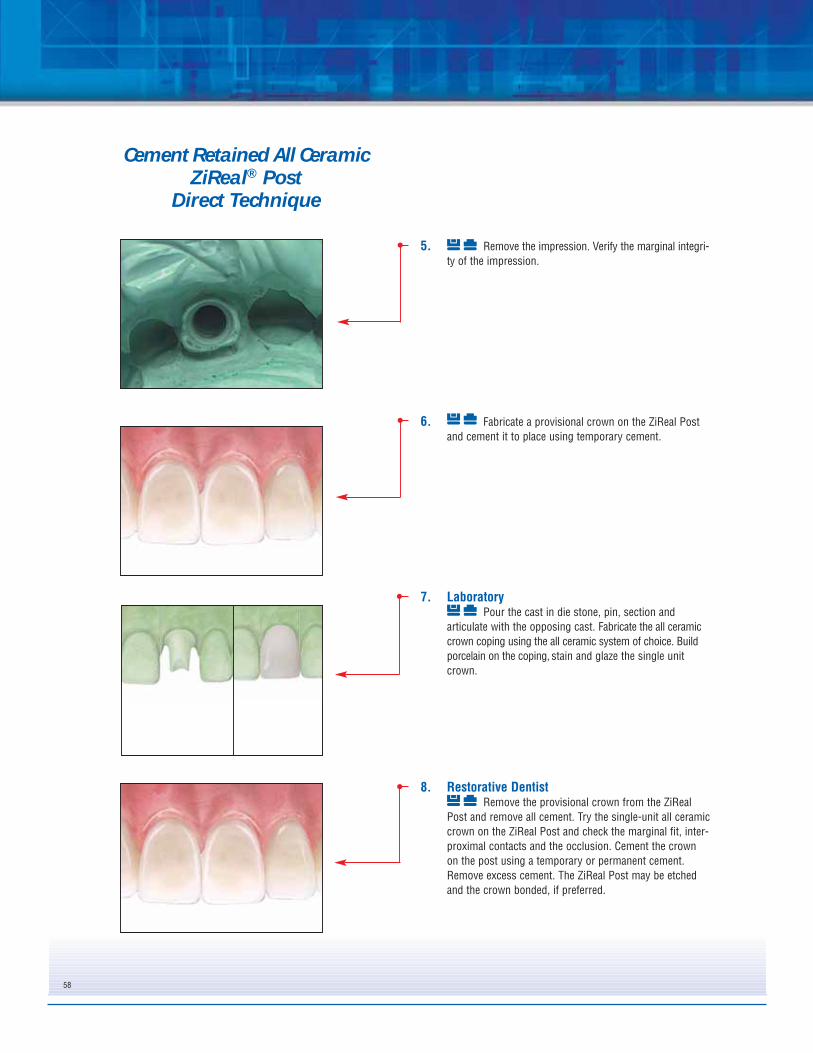
5. Remove the impression. Verify the marginal integri-ty of the impression.
6. Fabricate a provisional crown on the ZiReal Postand cement it to place using temporary cement.
7. LaboratoryPour the cast in die stone, pin, section and
articulate with the opposing cast. Fabricate the all ceramiccrown coping using the all ceramic system of choice. Buildporcelain on the coping, stain and glaze the single unitcrown.
8. Restorative DentistRemove the provisional crown from the ZiReal
Post and remove all cement. Try the single-unit all ceramiccrown on the ZiReal Post and check the marginal fit, inter-proximal contacts and the occlusion. Cement the crownon the post using a temporary or permanent cement.Remove excess cement. The ZiReal Post may be etchedand the crown bonded, if preferred.
Cement Retained All CeramicZiReal® Post
Direct Technique
59
Material:
Machined Gold Alloy Cylinder With Plastic Unitube
Indications:
• Laboratory Fabricated Custom Abutments• Single- and Multi-Unit Porcelain-Fused-to-Metal or All Ceramic
Restorations• Minimum Interarch Space of 6mm• Aesthetic Restorations When Tissue Height is Limited• Maximum Angulation Correction of 30°
1. Restorative DentistFollow the steps for Implant Level Impressions on
pages 11-13 for the Pick-Up Technique and pages 14-16for the Twist Lock™ Transfer Technique.
2. LaboratoryPlace the proper Hexed Gold UCLA Abutment into
the implant analog, line up the hex and press firmly untilhearing and feeling the audible and tactile click.(See page 6for finger deactivation instructions.)
or
Place the proper diameter Hexed Gold UCLAAbutment onto the implant analog, engaging the hex.
Thread a try-in or waxing screw into the analoguntil finger tight using a .048” Large Hex Driver. Reduce oradjust the plastic sleeve as necessary. Add wax to thewaxing sleeve to form the custom abutment with idealemergence, angulation and crown margins.
3. Carefully remove the waxed custom abutmentfrom the implant analog. Invest, burnout and cast the customabutment to the UCLA Gold Cylinder using a semi-preciousor high noble alloy (see page 9 for casting alloyspecifications). Divest and finish the custom abutment. Polishthe gold abutment collar and entire subgingival portion of theabutment with a polishing protector in place.
4. Place the finished custom abutment back onto theimplant analog in the cast and thread a try-in screw into theanalog until finger tight. Cover the access hole with wax.Wax the single-unit PFM crown coping on the custom abut-ment. Invest, burnout and cast the coping in a semi-preciousor high noble alloy. Opaque, build porcelain, stain and glazethe single-unit crown.
Cement Retained Single-Unit UCLA Custom Abutment
Indirect Technique
60
5. Restorative DentistRemove the healing abutment from the implant
using a .048” Large Hex Driver. To help prevent accidentalswallowing, thread floss through the spinner on the driver.
Activate the fingers using the QuickSeat® ActivatorTool. Place the custom abutment into the implant, line upthe hex and press firmly until hearing and feeling the audi-ble and tactile click. Thread a Certain® Gold-Tite® HexedScrew into the implant until finger tight using a .048”Large Hex Driver.
or
Place the custom abutment on the implant, engagingthe hex. Thread a Square Gold-Tite Screw into the implantuntil finger tight using a Square Driver.
Radiograph the interface to verify an accurate fit.
6. Try the single-unit crown on the custom abutment andcheck the marginal fit, interproximal contacts and theocclusion. Remove the crown.
Torque the Certain Gold-Tite Hexed Screw to 20Ncmusing a .048” Large Hex Driver Tip and a torque device.
or
Torque the Square Gold-Tite Screw to 32-35Ncmusing the Square Driver Tip and a torque device.
Place a protective material over the screw head.Seal the access hole with temporary filling material. Cementthe crown on the custom abutment using a temporary orpermanent cement. Remove excess cement.
Cement Retained Single-Unit UCLA Custom Abutment
Indirect Technique
61
1. Restorative DentistFollow the steps for Implant Level Impressions on
pages 11-13 for the Pick-Up Technique and pages 14-16for the Twist Lock™ Transfer Technique.
2. LaboratoryDeactivate the fingers on the Certain® Hexed Gold
UCLA Abutment using the QuickSeat® Activator Tool (seepage 6). Place the proper diameter Hexed Gold UCLAAbutments into each implant analog.
or
Place the proper diameter Hexed Gold or CastableUCLA Abutments on the implant analogs, engaging the hex.
Thread try-in or waxing screws into the analogsuntil finger tight using a .048” Large Hex Driver. Reduceor adjust the plastic sleeves as necessary. Add wax to thewaxing sleeves to form the custom abutments with idealemergence, angulation, parallelism and crown margins.
3. Carefully remove the wax custom abutments fromthe analogs. Invest, burnout and cast the custom abut-ments to the UCLA Gold Cylinders using a semi-preciousor high noble alloy (see page 9 for casting alloy specifica-tions). Divest and finish the custom abutments. Polish thegold abutment collars and entire subgingival portions withpolishing protectors in place.
4. Place the finished custom abutments back ontothe implant analogs in the cast and thread try-in screwsinto the analogs until finger tight using a .048” Large HexDriver. Cover the access holes with wax. Wax the multi-unit framework on the custom abutments. Invest, burnoutand cast the multi-unit framework in a semi-precious orhigh noble alloy. Return to the restorative dentist for metalframework try-in.
Cement Retained Multi-Unit UCLA Custom Abutment
Indirect Technique
62
5. Restorative DentistRemove the healing abutments from the implants
using a .048” Large Hex Driver. To help prevent accidentalswallowing, thread floss through the spinner on the driver.
Activate the fingers using the QuickSeat® ActivatorTool. Place the custom abutments into each implant, line upthe hex and press firmly until hearing and feeling theaudible and tactile click.
or
Place the custom abutments onto the implants,engaging the hex.
Thread a try-in screw into each abutment untilfinger tight using a .048” Large Hex Driver. Radiographthe interface of the implants to verify an accurate fit. Placethe multi-unit framework on the custom abutments andverify a passive fit. Cut and index the framework intraorallyif a fit discrepancy is found. Immediately replace the heal-ing abutments on the implants.
6. LaboratoryPlace the custom abutments back onto the implant
analogs in the cast and attach using try-in screws. Opaqueand build porcelain on the multi-unit framework. Stain andglaze the porcelain.
7. Restorative DentistRemove the healing abutments from the implants.
Activate the fingers using the QuickSeat ActivatorTool. Place the custom abutments into each implant, lineup the hex and press firmly until hearing and feeling theaudible and tactile click. Thread a Certain® Gold-Tite®
Hexed Large Diameter Screw into each implant until fingertight using a .048” Large Hex Driver.
or
Place the custom abutments onto the implantsengaging the hex. Thread the Square Gold-Tite Screws intothe implant until finger tight using a Square Driver.
Radiograph the interface of the implants to verify anaccurate fit.
Cement Retained Multi-Unit UCLA Custom Abutment
Indirect Technique
63
8. Try the multi-unit PFM bridge onto the customabutments. Verify marginal fit, interproximal contacts andthe occlusion.
Torque the Certain Gold-Tite® Hexed LargeDiameter Screws to 20Ncm using a .048” Large Hex DriverTip and a torque device.
or
Torque the Square Gold-Tite Screws to 32-35Ncmusing the Square Driver Tip and a torque device.
9. Place a protective material over the screw heads.Seal the access holes with temporary filling material.Cement the bridge on the abutments using a temporary orpermanent cement. Remove excess cement. Make anyocclusal adjustments necessary.
Cement Retained Multi-Unit UCLA Custom Abutment
Indirect Technique
64
1. Restorative DentistFollow the steps for Implant Level Impressions on
pages 11-13 for the Pick-Up Technique and pages 14-16for the Twist Lock™ Transfer Technique.
2. LaboratoryDeactivate the fingers on the Certain® Hexed Gold
UCLA Abutment before placement using the QuickSeat®
Activator Tool (see page 6). Place the proper diameterHexed Gold UCLA Abutment into the implant analog andline up the hex. Thread a try-in or waxing screw into theanalog until finger tight using a .048” Large Hex Driver.
or
Place the proper diameter Hexed Gold or CastableUCLA Abutment onto the implant analog and engage thehex. Thread a try-in or waxing screw into the analog untilfinger tight using a .048” Large Hex Driver.
Reduce or adjust the plastic sleeve as necessary.Wax the single-unit PFM coping to the waxing sleeve.
3. Remove the try-in or waxing screw and carefullyremove the wax coping from the analog. Invest, burnoutand cast the single-unit PFM coping to the UCLA GoldCylinder using a semi-precious or high noble alloy (seepage 9 for casting alloy specifications). Divest and finishthe coping.
Screw Retained Single-UnitUCLA Abutment
Indirect Technique
Material:
Machined Gold Alloy Cylinder With Plastic Unitube
Indications:
• Screw Retained Single- and Multi-Unit Porcelain-Fused-to-MetalRestorations
• Minimum Interarch Space 4mm
65
4. Place the cast coping back onto the implantanalog in the cast and thread a try-in or waxing screw intothe analog until finger tight. Opaque and build porcelain onthe single-unit coping. Stain and glaze the porcelain.Polish the abutment gold collar with a polishing protector inplace.
5. Restorative DentistRemove the healing abutment from the implant
using a .048” Large Hex Driver. To help prevent accidentalswallowing, thread floss through the spinner on the driver.
Activate the fingers using the QuickSeat® ActivatorTool. Place the single crown into the implant, line up thehex and press firmly until hearing and feeling the audibleand tactile click. Thread the Certain® Gold-Tite® HexedScrew into the implant until finger tight using a .048”Large Hex Driver.
or
Place the single-unit crown onto the implant,engaging the hex. Thread the Square Gold-Tite Screw intothe implant until finger tight using the Square Driver.
Radiograph the interface of the implant to verify anaccurate fit. Verify the interproximal contacts and theocclusion.
6. Torque the Certain Gold-Tite Hexed Screws to20Ncm using a .048” Large Hex Driver Tip and a torquedevice.
or
Torque the Square Gold-Tite Screw to 32-35Ncmusing the Square Driver Tip and a torque device.
7. Place a protective material over the screw head.Seal the access hole with a temporary filling material andcomposite resin. Make any occlusal adjustmentsnecessary.
Screw Retained Single-Unit UCLA Abutment
Indirect Technique
66
1. Restorative DentistFollow the steps for Implant Level Impressions on
page 11-13 for the Pick-Up Technique and pages 14-16 forthe Twist Lock™ Transfer Technique.
2. LaboratoryPlace the proper diameter Non-Hexed Gold or
Castable UCLA Abutments onto the implant analogs andthread try-in or waxing screws into the analogs until fingertight using a .048” Large Hex Driver. Reduce or adjust theplastic sleeves as necessary. Wax the multi-unit frame-work to the waxing sleeves.
3. Remove the try-in or waxing screws and carefullyremove the wax framework from the analogs. Invest,burnout and cast the multi-unit PFM framework to theUCLA Gold Cylinders using a semi-precious or high noblealloy (see page 9 for casting alloy specifications). Divestand finish the framework. Return to the restorative dentistfor metal framework try in.
4. Restorative DentistRemove the healing abutments from the implants
using a .048” Large Hex Driver. To help prevent accidentalswallowing, thread floss through the spinner on the driver.Place the multi-unit PFM framework onto the implants.Thread a try-in screw into the anterior most implant using aLarge Hex Driver. Radiograph the interface of all implants toverify a passive fit. Repeat after removing the screw andplacing it into the posterior most implant. Cut and index theframework intraorally if fit discrepancy is found.Immediately replace the healing abutments on the implants.
Screw Retained Multi-Unit UCLA Abutment
Indirect Technique
67
5. LaboratoryPlace the verified framework back onto the implant
analogs in the cast and thread try-in or waxing screws intothe analogs until finger tight. Opaque and build porcelain onthe multi-unit framework. Stain and glaze the porcelain.Polish the abutment gold collars with polishing protectorsin place.
6. Restorative DentistRemove the healing abutments from the implants
Place the multi-unit PFM bridge onto the implants.
Thread the Certain® Gold-Tite® Hexed LargeDiameter Screws into each implant until finger tight usinga .048” Large Hex Driver.
or
Thread the Square Gold-Tite Screws into eachimplant until finger tight using a Square Driver.
Radiograph the interface of the bridge on the implantsto verify a passive fit. Verify the interproximal contacts andthe occlusion.
7. Torque the Certain Gold-Tite Hexed LargeDiameter Screws to 20Ncm using a .048” Large HexDriver Tip and a torque device.
or
Torque the Square Gold-Tite Screw to 32-35Ncmusing the Square Driver Tip and a torque device.
8. Place a protective material over the screw heads.Seal the access holes with composite resin. Make anyocclusal adjustments necessary.
Screw Retained Multi-Unit UCLA Abutment
Indirect Technique
68
Material:
Titanium AlloyCommercially Pure Titanium
Indications:
• Single- and Multi-Unit Porcelain-Fused-to-Metal Restorations• Minimum Interarch Space of 7mm• Minimum Tissue Height of 2mm• Angle correction up to 25º
1. Surgeon or Restorative DentistSelect the proper Conical Abutment collar height
and angle (0º, 17º or 25º) for the implant by measuringthe height of the healing abutment above tissue, notincluding the dome portion. Subtract the measurementfrom the total height of the healing abutment and subtract2mm. Match the color of the implant platform. See page17 for Prosthetic Abutment Selection Guide.
2. Remove the healing abutment from the implantusing a .048” Large Hex Driver. To help prevent accidentalswallowing, thread floss through the spinner on the driver.
3. Activate the fingers using the QuickSeat® ActivatorTool. Place the proper height Conical Abutment into theimplant, line up the hex and press firmly until hearing andfeeling the audible and tactile click.
or
Place the proper height Conical Abutment onto theimplant, engaging the hex.
Thread the Conical Abutment Screw into theimplant by turning the spindle on the ASYST® Tool untilfinger tight. Remove the ASYST Tool or waxing screw.
If correcting an angle using the 17 or 25 degree AngledConical Abutment, place the abutment in or on the implanthex to correct angulation while holding onto the deliverytool. Place the abutment screw onto the implant driver andthread into implant.
4. Radiograph the interface to verify complete seat-ing of the abutment on the implant. Place the film perpendi-cular to the interface of the abutment on the implant.
5. Torque the Conical Abutment Screw into theimplant at 20Ncm using the Abutment Driver Tip and atorque device. (If the surgeon places the abutment, aConical Abutment Healing Cap is threaded onto the abut-ment using a .048” Large Hex Driver.)
6. Restorative DentistFollow the steps for Abutment Level Impressions
on page 11-13 for the Pick-Up Impression Technique andpages 14-16 for the Twist Lock™ Transfer Technique.
7. LaboratoryPlace a Hexed Conical Gold or Castable Cylinder
onto the conical analog. Thread with a waxing screw orretaining screw into the analog until finger tight using a.048” Large Hex Driver. Reduce or adjust the plastic sleeveas necessary. Wax the single-unit PFM coping to thewaxing sleeve.
8. Remove the retaining or waxing screw andcarefully remove the wax coping from the implant analog.Invest, burnout and cast the single-unit PFM coping to theConical Gold Cylinder using a semi-precious or high noblealloy (see page 9 for casting alloy specifications). Divestand finish the coping.
9. Place the finished coping back onto the Conicalanalog in the cast and thread a waxing or retaining screwinto the analog until finger tight. Opaque and build porcelainon the single-unit coping. Stain and glaze the porcelain.Polish the gold collar with a polishing protector in place.
10. Restorative DentistRemove the healing cap from the abutment using
a .048” Large Hex Driver. Place the single-unit PFM crownon the abutment, engaging the hex. Thread a Gold-Tite®
Retaining Screw into the abutment until finger tight usinga .048” Large Hex Driver. Radiograph the interface to veri-fy an accurate fit. Verify the interproximal contacts and theocclusion. Torque the screw to 10Ncm using a .048” LargeHex Driver Tip and a torque device.
11. Place a protective material over the screw head.Seal the access hole with a temporary filling material andcomposite resin. Make any occlusal adjustmentsnecessary.
1. Surgeon Or Restorative DentistSelect the proper Conical Abutment collar height
and angle (0º, 17º or 25º) for each implant by measuringthe height of the healing abutment above tissue, notincluding the dome portion. Subtract the measurementfrom the total height of the healing abutment and thensubtract 2mm. Match the color of implant platforms.
2. Remove the healing abutments from the implants,one at a time, using a .048” Large Hex Driver. To helpprevent accidental swallowing, thread floss through thespinner on the driver.
3. Activate the fingers using the QuickSeat® ActivatorTool. Place the proper height Conical Abutment into theimplants, line up the hex and press firmly until hearingand feeling the audible and tactile click.
or
Place the proper height Conical Abutment onto theimplants, engaging the hex.
Thread the Conical Abutment Screw into theimplant by turning the spindle on the ASYST® Tool untilfinger tight. Remove the ASYST Tool.
If correcting an angle using the 17 or 25 degree AngledConical Abutment, place the abutment in or on the implanthex to correct angulation while holding onto the deliverytool. Place the abutment screw onto the implant driver andthread into implant.
4. Radiograph the interfaces to verify completeseating of the abutments on the implants. Place the filmperpendicular to the interface of the abutments on theimplants.
5. Torque the Conical Abutment Screws into theimplants at 20Ncm using the Abutment Driver Tip and atorque device. (If the surgeon places the abutments,Conical Abutment Healing Caps are threaded onto theabutments using a .048” Large Hex Driver.)
6. Restorative DentistFollow the steps for Abutment Level Impressions
on pages 11-13 for the Pick-Up Technique and pages 14-16 for the Twist Lock™ Transfer Technique.
7. LaboratoryPlace the Non-Hexed Conical Gold or Castable
Cylinders onto the Conical Analogs and thread waxing orretaining screws into the analogs until finger tight using a.048” Large Hex Driver. Reduce or adjust the plasticsleeves as necessary. Wax the multi-unit PFM frameworkto the waxing sleeves.
8. Remove the retaining or waxing screws andcarefully remove the wax framework from the analogs.Invest, burnout and cast the multi-unit PFM framework tothe Conical Gold Cylinders using a semi-precious or highnoble alloy (see page 9 for casting alloy specifications).Divest and finish the framework. Return to the restorativedentist for metal framework try in.
9. Restorative DentistRemove the healing caps from the abutments.
Place the multi-unit PFM framework onto the abutments.Thread a Gold-Tite® Retaining Screw into the posteriormost abutment using a .048” Large Hex Driver. Radiographthe interface on the abutments to verify a passive fit.Repeat after removing the screw and placing it into theanterior most abutment. Cut and index the framework intra-orally if a fit discrepancy is found. Immediately replace thehealing caps on the abutments.
10. LaboratoryPlace the verified framework back onto the Conical
Analogs in the cast and thread retaining or waxing screwsinto the analogs until finger tight. Opaque and build porce-lain on the multi-unit framework. Stain and glaze theporcelain. Polish the gold collars with polishing protectorsin place.
11. Restorative DentistRemove the healing caps from the abutments.
Place the multi-unit PFM bridge onto the abutments. ThreadGold-Tite Retaining Screws into the abutments until fingertight using a Large Hex Driver. Radiograph the interface onthe abutments to verify a passive fit. Verify theinterproximal contacts and the occlusion. Torque thescrews to 10Ncm using a .048” Large Hex Driver Tip and atorque device. Place a protective material over the screwheads. Seal the access holes with temporary filling materialand composite resin. Make any occlusal adjustmentsnecessary.
• Multiple Implant, Bar Retained and Fixed Removable Overdentures• Minimum Space For Bar Construction is 7mm• Maximum Divergence of 30°
1. Surgeon Or Restorative DentistSelect the proper Standard Abutment collar height
for each implant by measuring the height of the healingabutment above tissue, not including the dome portion.Subtract the measurement from the total height of thehealing abutment and add 1mm. Match the color of theimplant platform.
2. Remove the healing abutments from the implants,one at a time, using a .048” Large Hex Driver. To helpprevent accidental swallowing, thread floss through thespinner on the driver.
3. Place the proper height Standard Abutment into theimplant and thread into place until finger tight.
or
Place the proper height Standard Abutment collaronto the implant, engaging the hex and thread theStandard Abutment Screw into the implant by turning thespindle on the ASYST® Tool until finger tight. Remove theASYST Tool.
4. Radiograph the interfaces to verify completeseating of the abutments on the implants. Place the filmperpendicular to the interface of the abutment on theimplant.
Bar Supported OverdentureStandard Abutment
Hader Bar
SEATED NOT
SEATED
75
5. Torque the Standard Abutment Screws into theimplants at 20Ncm using the Abutment Driver Tip and atorque device. (If the surgeon places the abutments,Standard Abutment Healing Caps are then threaded ontothe abutments using a .048” Large Hex Driver.) Thepatient’s existing denture is then relieved to the height ofthe abutments and/or healing caps.
Place the Standard Abutment Pick-Up ImpressionCopings onto the abutments. Thread the coping screwsinto the abutments using fingers then tighten using a.048” Large Hex Driver. Visually verify all copings areseated passively on the abutments. Impression copingsmay be splinted prior to impressioning.
7a. A custom or stock open top impression tray isused for the Pick-Up Impression Technique. Cut smallholes in the tray for the screws to protrude through. Try inthe tray to verify that the screw heads are visible throughthe openings.
8a. A medium or heavy body impression material isrecommended for the definitive impression. Syringeimpression material around each of the entire Pick-UpImpression Copings.
Bar Supported OverdentureStandard Abutment
Hader Bar
76
9a. Load the impression tray and seat in the mouth.Wipe impression material off the top of the screws beforeit sets. Allow the impression material to set per the manu-facturer’s instructions.
10a. After the impression material has set, unscrew andremove the Pick-Up Impression Coping Screws using a.048” Large Hex Driver. Remove the impression from themouth.
11a. Verify that the impression material has completelyadapted around each of the copings.
12a. Replace the Standard Abutment Healing Caps ontothe abutments using a .048” Large Hex Driver. Reline thepatient’s existing denture with a chair side, soft relinematerial over the abutments and healing caps.
Bar Supported OverdentureStandard Abutment
Hader Bar
77
13a. LaboratoryPlace the Standard Abutment Lab Analogs into
the impression copings and hold them in position whiletightening the screws. Verify that the analogs are seatedpassively.
14a. Pour the cast in die stone. After the stone has set,loosen the screws using a large Hex Driver until these dis-engage from the analogs. Remove the impression fromthe stone cast. Go to Step 15.
Transfer Technique6b. Restorative Dentist-Transfer Technique
Thread the Standard Abutment Transfer Copingsinto the abutments using fingers; then tighten using theTransfer Impression Coping Driver. Visually verify that allcopings are seated passively on the abutments.
7b. A custom or stock closed top impression tray isused for the transfer impression technique. Allow forapproximately 2mm of space between the tray and top ofthe copings. The copings are 9mm in height.
Bar Supported OverdentureStandard Abutment
Hader Bar
78
8b. A medium or heavy body impression material isrecommended for the definitive impression. Syringeimpression material around each of the entire transferimpression copings.
9b. Load the impression tray and seat in the mouth.Allow the impression material to set per the manufacturer’sinstructions.
10b. After the impression material has set, remove theimpression from the mouth. The transfer impression cop-ings will stay on the abutments in the mouth. Verify thatthe material completely adapted around each of the cop-ings.
11b. Remove the transfer impression copings from theabutments.
Bar Supported OverdentureStandard Abutment
Hader Bar
79
12b. Replace the Standard Abutment Healing Capsonto the abutments using a Large Hex Driver. Reline thepatient’s existing denture with a chair side, soft relinematerial over the abutments and healing caps.
13b. LaboratoryScrew the transfer copings onto the Standard
Abutment analogs and verify that these are passively seat-ed. Holding onto the analog, press each transfer copinginto the impression firmly. The coping is fully seated whenthe retentive groove engages.
14b. Pour the cast in die stone. After the stone has set,remove the impression from the cast. Unscrew the trans-fer copings from the analogs. Go to Step 15.
15. Place the Standard Abutment Gold or CastableCylinders onto the Standard Abutment Analogs and threadwaxing or retaining screws into the analogs until finger tightusing a .048” Large Hex Driver. Fabricate a verification indexby luting the plastic sleeves together using a low expansionlight cure composite resin or autopolymerizing acrylic resin.Also, fabricate a baseplate and wax occlusal rim.
Bar Supported OverdentureStandard Abutment
Hader Bar
80
16. Restorative DentistRemove the healing caps using a .048” Large Hex
Driver. Place the occlusal rim into the mouth. Make theinterocclusal records. Place the verification index onto theabutments. Place a Hexed Gold-Tite® Retaining Screw intoone posterior-most cylinder and finger tighten. Visuallyverify that all cylinders are seated passively on theabutments. Remove the screw and place it into the oppositeposterior-most cylinder and repeat. If a fit discrepancy isfound, section the index and reassemble intraorally. Removethe index. Replace the healing caps.
17. LaboratoryVerify that the analog positions on the cast are
accurate using the verification index. If a fit discrepancy isfound, remove the analog and replace it in the cast using the verification index. Articulate casts using the interocclusal record. Set denture teeth on the baseplate andwax for try-in.
18. Restorative DentistPlace the wax try-in into the mouth. Verify the
occlusion, aesthetics and phonetics. Make any adjustmentsnecessary. If major adjustments are necessary, make anew interocclusal record and return to the laboratory for anew set up and try-in.
19. LaboratoryMake a plaster or silicone matrix of the verified
wax try-in and remove the denture teeth inside it. or
Request a CAM StructSURE™ Precision Milled Bar. See CAM StructSURE Manual (ART861)
Bar Supported OverdentureStandard Abutment
Hader Bar
81
20. Carefully remove the Standard Abutment Gold orCastable Cylinders from the verification index. Place thecylinders onto the analogs and thread waxing screws intothe analogs until finger tight. Adjust the height of thesleeves as necessary. Wax the bar patterns (andattachments, if used) to the waxing sleeves. Use thematrix on the cast to position the bar within the confinesof the wax try-in.
21. Remove the Hader Bar wax-up from the cast.Invest, burnout and cast the bar in a semi-precious orhigh noble alloy (see page 9 for casting alloy specifica-tions). Divest, finish and polish the bar with polishingprotectors in place. Return the bar to the restorativedentist for try in and fit verification.
22. Restorative DentistRemove the healing caps from the abutments.
Place the bar onto the abutments. Thread a Hexed Gold-Tite® Retaining Screw into one posterior-most abutmentand finger tighten. Visually verify that the bar is seatedpassively on all abutments. Repeat after removing thescrew and placing it into the opposite posterior-mostabutment. If fit discrepancy is found, cut and index the barintraorally for soldering. Replace the healing caps.
23. LaboratoryTransfer the denture teeth back onto the cast
using the matrix and wax the denture for processing. Flaskthe waxed denture and boil out. Separate the flask andattach the Hader Bar onto the analogs in the cast usingretaining screws. Block out all undercuts and access open-ings with wax. Place the Hader clips and/or other attach-ments onto the bar. Process and finish the denture follow-ing conventional procedures.
Bar Supported OverdentureStandard Abutment
Hader Bar
82
24. Restorative DentistRemove the healing caps. Place the Hader Bar
onto the abutments. Thread the Hexed Gold-Tite® RetainingScrews into the abutments and torque these to 10Ncmusing a .048” Large Hex Driver Tip and a torque device.
25. Place the overdenture onto the Hader Bar in themouth and engage the retentive attachments. Makeocclusal or tissue adjustments as necessary. Instruct thepatient on insertion and removal of the prosthesis and oralhygiene maintenance.
Bar Supported OverdentureStandard Abutment
Hader Bar
83
1. Restorative DentistFollow the steps for Standard Abutment
Impressions on pages 74-79 for the Pick-Up or TransferTechnique.
2. LaboratoryFollow the steps on page 81 and 82 for fabrication
of the verification index, baseplate and wax occlusal rim,wax try-in and plaster or silicone matrix.
or
Request a CAM StructSURE™ Precision Milled Bar. See CAM StructSURE Manual (ART861)
3. Carefully remove the Standard Abutment Gold orCastable Cylinders from the verification index. Place thecylinders onto the analogs and attach with waxing screwsusing a .048” Large Hex Driver. Adjust the height of thesleeves as necessary. Wax the hybrid bar patterns to thewaxing sleeves and add acrylic resin retention to the topof the bar. Use the matrix on the cast to position the barwithin the confines of the wax try-in.
4. Remove the hybrid bar wax up from the cast.Invest, burnout and cast the bar in a semi-precious orhigh noble alloy (see page 9 for casting alloy specifica-tions). Divest, finish and polish the under surface of thebar with polishing protectors in place. Return the bar tothe restorative dentist for try in and fit verification.
5. Restorative DentistRemove the healing caps from the abutments
using a .048” Large Hex Driver. To help prevent accidentalswallowing, thread floss through the spinner on the driver.Place the bar onto the abutments. Thread a Hexed Gold-Tite® Retaining Screw into one posterior-most cylinderand finger tighten. Visually verify the bar is seatedpassively on all implants. Repeat after removing the screwand placing it into the opposite posterior-most cylinder. Ifa fit discrepancy is found, cut and index the bar intraorallyfor soldering. Replace the healing caps.
6. LaboratoryAttach the bar onto the analogs with waxing
screws using a Large Hex Driver. Transfer the dentureteeth from the matrix onto the bar on the cast and wax thehybrid prosthesis for processing. Flask the waxedprothesis and boil out. Separate the flask. Opaque the barin areas where the acrylic will be processed to it. Blockout all undercuts with wax. Process and finish the hybridprosthesis in a conventional fashion. Polishing protectorsshould be in place during all finishing and polishingprocedures.
7. Restorative DentistRemove the healing caps. Place the fixed hybrid
prosthesis onto the abutments. Screw the Hexed Gold-TiteRetaining Screws into the abutments. Adjust occlusion,remove and polish. Replace prosthesis and torque thescrews 10Ncm using a .048” Large Hex Driver Tip and atorque device. Place a protective material over the screwheads. Seal the access holes with acrylic resin. Make anyocclusal adjustments necessary. Instruct the patient onoral hygiene maintenance of the prosthesis.
Indications:• Multiple Implant Bar Retained and Fixed Removable Overdentures• Minimum Space For Bar Construction is 5mm• Maximum Angulation Correction of 30°
1. Restorative DentistFollow the steps for Implant Level Impressions on
pages 12-13 for the Pick-Up Technique and pages 14-16for the Twist Lock™ Transfer Technique.
2. LaboratoryPlace the Non-Hexed Gold or Castable UCLA
Abutments onto the implant analogs and thread waxingscrews or try-in screws into the analogs until finger tightusing a .048” Large Hex Driver. Fabricate a verification indexby luting the plastic sleeves together using a low expansionlight cure composite resin or autopolymerizing acrylic resin.Also, fabricate a baseplate and wax occlusal rim.
3. Restorative DentistRemove the healing abutments using a .048”
Large Hex Driver. To help prevent accidental swallowing,thread floss through the spinner on the driver. Place theocclusal rim into the mouth. Make the interocclusalrecords. Place the verification index onto the implants.Place a try-in screw into one posterior-most UCLAAbutment and finger tighten. Radiograph the interfaces toverify that all cylinders are seated passively on theimplants. Remove the screw and place it into the oppositeposterior-most UCLA Abutment and repeat. If a fitdiscrepancy is found, section the index and reassembleintraorally. Remove the index. Immediately replace thehealing abutments.
4. LaboratoryVerify that analog positions on the cast are accu-
rate using the verification index. If a fit discrepancy isfound, remove the analog and replace it in the cast usingthe verification index. Articulate casts using the inter-occlusal record. Set the denture teeth on the baseplateand wax for try in.
Bar Supported OverdentureUCLA Abutment
Hader Bar
86
5. Restorative DentistPlace the wax try-in into the mouth. Verify the
occlusion, aesthetics and phonetics. Make any adjustmentsnecessary. If major adjustments are necessary, make anew interocclusal record and return to the laboratory for anew set up and try-in.
6. LaboratoryMake a plaster or silicone matrix of the verified
wax try-in and remove the denture teeth inside it.
or
Request a CAM StructSURE™ Precision Milled Bar. See CAM StructSURE Manual (ART861)
7. Carefully remove the UCLA Abutments from theverification index. Place the UCLA Abutments onto theimplant analogs and thread waxing screws into theanalogs until finger tight using a .048” Large Hex Driver.Adjust the height of the sleeves as necessary. Wax the barpatterns (and attachments, if used) to the waxing sleeves.Use the matrix on the cast to position the bar within theconfines of the wax try-in.
8. Remove the Hader Bar wax-up from the cast.Invest, burnout and cast the Hader Bar in a semi-preciousor high noble alloy (see page 9 for casting alloyspecifications). Divest, finish and polish the bar withpolishing protectors in place. Return the bar to therestorative dentist for try in and fit verification.
Bar Supported OverdentureUCLA Abutment
Hader Bar
87
9. Restorative DentistRemove the healing abutments from the implants.
Place the bar onto the implants. Thread a try-in screw intoone posterior-most implant. Radiograph the interfaces toverify that the bar is seated passively on all implants.Repeat after removing the screw and placing it into theopposite posterior-most implant. If a fit discrepancy isfound, cut and index the bar intraorally for soldering.Immediately replace the healing abutments on the implants.
10. LaboratoryTransfer the denture teeth back onto the cast
using the matrix and wax the denture for processing. Flaskthe waxed denture and boil out. Separate the flask andattach the Hader Bar onto the analogs in the cast usingtry-in screws. Block out all undercuts and access openingswith wax. Place the Hader clips and/or other attachmentsonto the bar. Process and finish the denture following con-ventional procedures.
11. Restorative DentistRemove the healing abutments from the implants.
Place the Hader Bar onto the implants.
Thread a Certain® Gold-Tite® Hexed LargeDiameter Screw into each implant until finger tight using a.048” Large Hex Driver.
or
Thread a Square Gold-Tite Screw into each implantuntil finger tight using a Square Driver.
Radiograph the interface of the implants to verify apassive fit. Torque the Certain Gold-Tite Hexed LargeDiameter Screws to 20Ncm and Square Gold-Tite Screws to32-35Ncm using the proper driver tip and a torque device.
12. Place the overdenture onto the Hader Bar in themouth and engage the retentive attachments. Makeocclusal or tissue adjustments as necessary. Instructpatient on insertion and removal of the prosthesis and oralhygiene maintenance.
Bar Supported OverdentureUCLA Abutment
Hader Bar
88
1. Restorative DentistFollow the steps for Implant Level Impressions on
pages 12-13 for the Pick-Up Technique and pages 14-16for the Twist Lock™ Transfer Technique.
2. LaboratoryPlace the Non-Hexed Gold or Castable UCLA
Abutments onto the implant analogs and thread waxing ortry-in screws into the analogs until finger tight using a.048” Large Hex Driver. Fabricate a verification index byluting the plastic sleeves together using a low expansionlight cure composite resin or autopolymerizing acrylicresin. Also, fabricate a baseplate and wax occlusal rim.
3. Restorative DentistRemove the healing abutments using a .048”
Large Hex Driver. To help prevent accidental swallowing,thread floss through the spinner on the driver. Place theocclusal rim into the mouth. Make the interocclusalrecords. Place the verification index onto the implants.Thread a try-in screw into one posterior-most UCLAAbutment and finger tighten. Radiograph the interfaces toverify that all cylinders are seated passively on theimplants. Remove the screw and place it into the oppositeposterior-most UCLA Abutment and repeat. If a fitdiscrepancy is found, section the index and reassembleintraorally. Remove the index. Immediately replace thehealing abutments.
4. LaboratoryVerify that the analog positions on the cast are
accurate using the verification index. If a fit discrepancy isfound, remove the analog and replace it in the cast usingthe verification index. Articulate the casts using the inter-occlusal record. Set the denture teeth on the baseplate tofirst molar occlusion only and wax for try in.
Implant Retained Fixed ProsthesisUCLA Abutment
Fixed Hybrid
89
5. Restorative DentistPlace the wax try-in into the mouth. Verify the
occlusion, aesthetics and phonetics. Make any adjust-ments necessary. If major adjustments are necessary,make a new interocclusal record and return to the labora-tory for a new set up and try-in.
6. LaboratoryMake a plaster or silicone matrix of the verified
wax try-in and remove the denture teeth inside it.
or
Request a CAM StructSURE™ Precision Milled Bar. See CAM StructSURE Manual (ART861)
7. Carefully remove the UCLA Abutments from theverification index. Place the Non-Hexed UCLA Abutmentsonto the implant analogs and thread try-in or waxingscrews into the analogs until finger tight using a .048”Large Hex Driver. Adjust the height of the plastic sleevesas necessary. Wax the hybrid bar patterns to the waxsleeves and add acrylic resin retention on the top. Use thematrix on the cast to position the bar within the confines ofthe wax try-in.
8. Remove the hybrid bar wax-up from the cast.Invest, burnout and cast the hybrid bar in a semi-preciousor high noble alloy (see page 9 for casting alloy specifica-tions). Divest, finish and polish the under surface of thebar with polishing protectors in place. Return the bar tothe restorative dentist for try in and fit verification.
Implant Retained Fixed ProsthesisUCLA Abutment
Fixed Hybrid
90
9. Restorative DentistRemove the healing abutments from the implants.
Place the bar onto the implants. Thread a try-in screw intoone posterior-most implant. Radiograph the interface of allimplants. Repeat after removing the screw and placing itinto the opposite posterior-most implant. If a fitdiscrepancy is found, cut and index the bar intraorally forsoldering. Immediately replace the healing abutments onthe implants.
10. LaboratoryAttach the bar onto the implant analogs with
waxing screws using a Large Hex Driver. Transfer thedenture teeth from the matrix onto the bar on the cast andwax the hybrid prosthesis for processing. Flask the waxedprosthesis and boil out. Separate the flask. Opaque the barin areas where the acrylic will be processed to it. Blockout all undercuts with wax. Process and finish the hybridprosthesis in conventional fashion. Polishing protectorsshould be in place during all finishing and polishingprocedures.
11. Restorative DentistRemove the healing abutments from the implants.
Place the Fixed Hybrid prosthesis onto the implants.
Thread a Certain® Gold-Tite® Hexed LargeDiameter Screw into each implant until finger tight using aLarge Hex Driver.
or
Thread a Square Gold-Tite Screw into eachimplant until finger tight using a Square Driver.
Radiograph the interface of the implants to verify apassive fit. Torque the Certain Gold-Tite Hexed LargeDiameter Screws to 20Ncm and Square Gold-Tite Screwsto 32-35Ncm using the proper driver tip and a torquedevice. Place a protective material over the screw heads.Seal the access holes with acrylic resin. Make anyocclusal adjustments necessary. Instruct the patient onoral hygiene maintenance of the prosthesis.
• Tissue Supported Removable Overdentures on Two to Four Implants• Partially Edentulous Overdentures With One or More Implants• Minimum Interarch Distance of 4mm• Angle Correction With Up to 40º Between Divergent Implants
1. Surgeon Or Restorative DentistSelect the proper LOCATOR Abutment collar
height for each implant by measuring the height of thehealing abutment above tissue, not including the domeportion. Subtract the measurement from the total height ofthe healing abutment and add 1mm.
2. Remove the healing abutments from the implants,one at a time, using a .048” Large Hex Driver. To helpprevent accidental swallowing, thread floss through thespinner on the driver.
3. Thread the proper height LOCATOR Abutment intothe implant using the plastic delivery tool packaged withthe abutment. Use the LOCATOR Driver to finger tighten.
4. Radiograph the interfaces to verify completeseating of the abutments on the implants. Place the filmperpendicular to the interface of the abutment on theimplant.
Tissue Supported OverdentureLOCATOR® Abutment
Indirect Technique
SEATED NOT SEATED
92
5. Torque the LOCATOR Abutments into the implantsat 20Ncm, using the LOCATOR Abutment Driver and a.050 inch hex driver tip in a torque device. (If the surgeonplaces the abutments, the patient’s existing denture will berelieved to allow for the abutments.)
or
Place the LOCATOR Driver Tip into the torque device andtorque the abutments to 20Ncm.
6. Restorative DentistA custom or stock closed top impression tray
may be used. Provide relief for the height of the LOCATORAbutments and impression copings plus 2mm. Theimpression copings are 4.5mm in height.
7. Place the LOCATOR Impression Copings on theabutments and verify complete seating. A medium orheavy body impression material is recommended. Syringeimpression material around each of the entire LOCATORImpression Copings.
8. Load the impression tray and seat in the mouth.Allow the impression material to set per the manufactur-er’s instructions.
Tissue Supported OverdentureLOCATOR® Abutment
Indirect Technique
93
9. Remove the impression from the mouth and verifythat the impression material completely adapted aroundeach coping. The impression copings should remaininside the impression. Relieve the patient’s existingdenture to allow for the LOCATOR Abutments. Place achair side soft liner into the denture around the abutmentsand seat the denture. Have the patient close into centricocclusion. Allow the soft liner to set per the manufacturer’s instructions.
10. LaboratoryInsert the LOCATOR Lab Analogs into the impres-
sion copings using firm pressure until these fully engage.
11. Pour the cast in die stone, being careful to notdislodge the analogs. Fabricate a baseplate and a waxocclusal rim.
12. Restorative DentistPlace the occlusal rim into the mouth. Make the
interocclusal records.
Tissue Supported OverdentureLOCATOR® Abutment
Indirect Technique
94
13. Laboratory Articulate casts using the interocclusal record. Set
the denture teeth on the baseplate and wax for try in.
14. Restorative DentistPlace the wax try-in into the mouth. Verify
occlusion, aesthetics and phonics. Make any adjustmentsnecessary. If major adjustments are necessary, make anew interocclusal record and return to the laboratory for anew set up and try-in.
15. LaboratoryAfter the wax try-in is verified, flask the denture
on the cast. Boil out the wax and separate the flask. Placethe LOCATOR White Spacer Rings over the analogs to pre-vent acrylic from flowing under the housings. Place theHousing/Black Processing Male Attachment assembliesonto the analogs.
16. Process and finish the denture with the LOCATORHousings in place. Remove the Black Processing Malesand replace with Final Male Attachments (see step 18).
Tissue Supported OverdentureLOCATOR® Abutment
Indirect Technique
95
17. Restorative DentistPlace the overdenture onto the LOCATOR
Abutments in the mouth engaging the attachments. Makeany occlusal or tissue adjustments necessary. Instruct thepatient on insertion and removal of the prosthesis and oralhygiene maintenance.
18. Remove the Black Processing Male by placing theRemoval Tip end of the LOCATOR Core Tool into theHousing/Black Processing Male assembly and turning thespinner 3 rotations counter clockwise. Place the Final MaleAttachment on the attachment insertion end of the CoreTool and press it firmly into the housing. The attachmentretention on the abutment may be reduced by placing thepink Light Retention Male or the blue Extra Light RetentionMale rather than the clear Final Male. The male attach-ments are replaced after normal wear by inserting theRemoval Tip straight into the bottom of the nylon male.Tilt the tool so the sharp edge will grab hold of the maleand pull it out of the cap.
Tissue Supported OverdentureLOCATOR® Abutment
Indirect Technique
96
1. Restorative DentistFollow steps 1-5 on pages 91 and 92 for LOCATOR
Abutment Indirect Technique selection and placement.
2. A direct chair side processing technique may beused for a patient’s existing denture or a new denture bycutting relief and lingual vent windows in the acrylic resindenture base over the abutment areas.
3. Cut two small pieces of rubber dam and place ahole in the center of each. Place these over the abutmentsto protect the tissue. Place the White Spacer Rings overthe LOCATOR Abutments to prevent acrylic resin from flow-ing into under-cuts around the housings. Place theHousing/Black Processing Male Attachment assembliesonto the LOCATOR Abutments in the mouth. Try in thedenture over the housings to verify it is fully seated on theridge and the housings are not in contact with the denture.
4. Place autopolymerizing acrylic resin or light curecomposite resin over the LOCATOR Housings and intorelief areas of the denture. Place the denture into positionin the mouth and have the patient close into centric occlu-sion. Allow the acrylic resin to set per the manufacturer’sinstructions.
Tissue Supported OverdentureLOCATOR® Abutment
Direct Technique
5. Remove the denture, fill any voids around thehousings and polish. Remove the Black Processing Malesand replace these with the Final Male Attachments (seestep 6). Place the overdenture onto the LOCATORAbutments in the mouth, engaging the attachments. Makeany occlusal or tissue adjustments necessary. Instruct thepatient on insertion and removal of the prosthesis and oralhygiene maintenance.
6. Remove the Black Processing Male by placing theRemoval Tip end of the LOCATOR Core Tool into theHousing/Black Processing Male assembly and turning thespinner 3 rotations counter clockwise. Place the Final MaleAttachment on the attachment insertion end of the CoreTool and press it firmly into the housing. The attachmentretention on the abutment may be reduced by placing thepink Light Retention Male or the blue Extra Light RetentionMale rather than the clear Final Male. The male attach-ments are replaced after normal wear by inserting theRemoval Tip straight into the bottom of the nylon male.Tilt the tool so the sharp edge will grab hold of the maleand pull it out of the cap.
• Tissue Supported Overdentures on Two to Four Implants• Partially Edentulous Overdentures With One or More Implants• Rigid Retention• Minimum Interarch Space of 5mm• Maximum Tissue Height of 6mm• Recommended for Parallel Implants;
(See Castable Dal-Ro System for Divergent Implants)• 250–1000 Grams of Retention; May Be Adjusted
1. Surgeon Or Restorative DentistSelect the proper Dal-Ro Abutment collar height
for each implant by measuring the height of the healingabutment above tissue, not including the dome portion.Subtract the measurement from the total height of thehealing abutment and add 1mm.
2. Remove the healing abutments from the implants,one at a time, using a .048” Large Hex Driver. To helpprevent accidental swallowing, thread floss through thespinner on the driver.
3. Place the proper height Dal-Ro Abutment collaronto the implant engaging the hex. Thread the Dal-RoAbutment Screw into the implant by engaging the hexbelow the ball with the O-Ring/Dal-Ro Driver. Finger tight-en the screws.
4. Radiograph the interface to verify complete seat-ing of the abutments on the implants. Place the film per-pendicular to the interface of the abutment on the implant.
5. Torque the Dal-Ro Abutment Screws into theimplants at 20Ncm using the O-Ring/Dal-Ro Driver Tip in atorque device. (If the surgeon places the abutments, thepatient’s existing denture will be relieved to allow for theabutments.)
6. Restorative DentistA custom or stock closed top impression tray
may be used. Provide relief for the height of the Dal-RoAbutments plus 2mm.
7. A medium or heavy body impression material isrecommended. Syringe impression material around eachDal-Ro Abutment.
Note:There are no impression copings for Dal-Ro Abutments.
8. Load the impression tray and seat in the mouth.Allow the impression material to set per the manufactur-er’s instructions.
9. Remove the impression from the mouth and verifythat the impression material completely adapted aroundeach abutment. Relieve the patient’s existing denture toallow for the Dal-Ro Abutments. Place a chair side softliner into the patient’s existing denture around the abut-ments and seat the denture. Have the patient close intocentric occlusion. Allow the soft liner to set per the manufacturer’s instructions.
10. LaboratoryInsert the Dal-Ro Lab Analogs into the impression
using firm pressure until the ball portion fully engages theundercut.
11. Pour the cast in die stone, being careful to not dis-lodge the analogs. Fabricate a baseplate and a waxocclusal rim.
12. Restorative Dentist Place the occlusal rim into the mouth. Make the
13. Laboratory Articulate casts using the interocclusal record. Set
the denture teeth on the baseplate and wax for try in.
14. Restorative DentistPlace the wax try-in into the mouth. Verify occlusion,
aesthetics and phonics. Make any adjustments necessary.If major adjustments are necessary, make a new inter-occlusal record and return to the laboratory for a new setup and try-in.
15. LaboratoryAfter the wax try-in is verified, flask the denture
on the cast. Boil out the wax and separate the flask. Placethe Dal-Ro Spacer Rings over the ball portion of theanalogs and conform to the ridges. Screw the Gold FemaleAttachments into the housings using the Female DriverTool. Place the housing/attachment assemblies onto theanalogs.
16. Process and finish the denture with the Dal-RoHousings in place.
17. Restorative DentistPlace the overdenture onto the Dal-Ro Abutments
in the mouth engaging the attachments. Make any occlusalor tissue adjustments necessary. Instruct the patient oninsertion and removal of the prosthesis and oral hygienemaintenance.
18. The Gold Female Attachment retention on theabutment may be adjusted by tightening the housing formore retention and loosening for less retention, using theFemale Attachment Tool. The Gold Females may bereplaced using the same technique.
1. Restorative DentistFollow steps 1-5 on pages 98 and 99 for Dal-Ro
Abutment selection and placement.
2. A direct chair side processing technique may beused for a patient’s existing denture or a new denture bycutting relief and lingual vent windows in the acrylic resindenture base over the abutment areas.
3. Cut two small pieces of rubber dam and place ahole in the center. Place these over the abutments to protectthe tissue. Screw the Gold Female Attachments into thehousings using the Female Attachment Tool. Place thehousing/attachment assemblies onto the Dal-RoAbutments in the mouth. Block out the undercuts with waxto prevent acrylic resin from flowing under the housings.Try in the denture over the housings to verify it is fullyseated on the ridge and the housings are not in contactwith the denture.
4. Place autopolymerizing acrylic resin or light curecomposite resin over the Dal-Ro Housings and into reliefareas of the denture. Place the denture into position in themouth and have the patient close into centric occlusion.Allow the acrylic resin to set per the manufacturer’sinstructions.
Tissue Supported OverdentureDal-Ro Abutment Direct Technique
104
5. Remove the denture, fill any voids around thehousings and polish. Place the overdenture onto the Dal-Ro Abutments in the mouth engaging the attachments.Make any occlusal or tissue adjustments necessary.Instruct the patient on insertion and removal of the pros-thesis and oral hygiene maintenance.
6. The Gold Female Attachment retention on theabutment may be adjusted by tightening the housing formore retention and loosening for less retention using theFemale Attachment Tool. The Gold Females may bereplaced using the same technique.
Tissue Supported OverdentureDal-Ro Abutment Direct Technique
105
Material:
Abutment: Commercially Pure TitaniumO-Ring: BunaHousing: Titanium Alloy
Indications:
• Tissue Supported Overdenture Retained by Two to Four Implants• Partially Edentulous Overdentures With One or More Implants• Resilient Retention• Minimum Interarch Space of 7mm• Maximum Tissue Height of 6mm• Recommended for Parallel Implants
(See Castable O-Ring System for Divergent Implants)• 850 Grams of Retention
1. Surgeon or Restorative DentistSelect the proper O-Ring Abutment collar height
for each implant by measuring the height of the healingabutment above tissue, not including the dome portion.Subtract the measurement from the total height of thehealing abutment and add 1mm.
2. Remove the healing abutments from the implants,one at a time, using a .048” Large Hex Driver. To helpprevent accidental swallowing, thread floss through thespinner on the driver.
3. Place the proper height O-Ring Abutment collaronto the implant engaging the hex. Thread the O-RingAbutment Screw into the implant by engaging the hexbelow the ball with the O-Ring/Dal-Ro Driver. Fingertighten the screws.
4. Radiograph the interfaces to verify completeseating of the abutments on the implants. Place the filmperpendicular to the interface of the abutment on theimplant.
5. Torque the O-Ring Abutment Screws into theimplants at 20Ncm using the O-Ring/Dal-Ro Driver Tip ina torque device. (If the surgeon places the abutments, thepatient’s existing denture will be relieved to allow for theabutments.)
6. Restorative DentistA custom or stock closed top impression tray
may be used. Provide relief in the tray for the height of theO-Ring Abutments plus 2mm.
7. A medium or heavy body impression material isrecommended. Syringe impression material around eachO-Ring Abutment.
Note: There are no impression copings for O-Ring Abutments.
8. Load the impression tray and seat in the mouth.Allow the impression material to set per the manufactur-er’s instructions.
9. Remove the impression from the mouth and verifythat the impression material completely adapted aroundeach abutment. Relieve the patient’s existing denture toallow for the Dal-Ro Abutments. Place a chair side softliner into the denture around the abutments and seat thedenture. Have the patient close into centric occlusion. Allowthe soft liner to set per the manufacturer’s instructions.
10. LaboratoryInsert the O-Ring Lab Analogs into the impression
using firm pressure until the ball portion fully engages theundercut.
11. Pour the cast in stone, being careful to not dis-lodge the analogs. Fabricate a baseplate and a waxocclusal rim.
12. Restorative DentistPlace the occlusal rim into the mouth. Make the
13. LaboratoryArticulate casts using the interocclusal record. Set
the denture teeth on the baseplate and wax for try-in.
14. Restorative DentistPlace the wax try-in into the mouth. Verify occlu-
sion, aesthetics and phonics. Make any adjustments nec-essary. If major adjustments are necessary, make a newinterocclusal record and return to the laboratory for a newset up and try-in.
15. Laboratory After the wax try-in is verified, flask the denture
on the cast. Boil out the wax and separate the flask. Placethe Red Processing O-Rings into the Housings. Place theHousing/O-Ring assemblies onto the analogs. Block out theundercuts with wax to prevent acrylic resin from flowingunder the Housings.
16. Process and finish the denture with the O-RingHousings in place. Remove the Red Processing O-Ringsand replace with the Black O-Rings (see step 18).
17. Restorative DentistPlace the overdenture onto the O-Ring Abutments
in the mouth engaging the attachments. Make anyocclusal or tissue adjustments necessary. Instruct thepatient on insertion and removal of the prosthesis and oralhygiene maintenance.
18. Normal wear will require that the O-Rings bereplaced periodically. Remove the existing O-Ring fromthe housing using an explorer and replace with a newBlack O-Ring.
1. Surgeon Or Restorative DentistFollow steps 1-5 on pages 105 and 106 for O-Ring
Abutment selection and placement.
2. A direct, chair side processing technique may beused for a patient’s existing denture or a new denture bycutting relief and lingual vent windows in the acrylic resindenture base over the abutment areas.
3. Cut two small pieces of rubber dam and place ahole in the center. Place these over the abutments toprotect the tissue. Place the Red Processing O-Rings intothe housings. Place the O-Ring Housing assemblies ontothe O-Ring Abutments in the mouth. Block out theundercuts with wax to prevent acrylic resin from flowingunder the housings. Try in the denture over the housingsto verify it is fully seated on the ridge and the housingsare not in contact with the denture.
4. Place autopolymerizing acrylic resin or light curecomposite resin over the O-Ring Housings and into therelief areas of the denture. Place the denture into positionin the mouth and have the patient close into centricocclusion. Allow the acrylic resin to set per themanufacturer’s instructions.
Tissue Supported OverdentureO-Ring Abutment Direct Technique
111
5. Remove the denture, fill any voids around thehousings and polish. Remove the Red Processing O-Ringsand replace with the Black O-Rings (see step 6). Place theoverdenture onto the O-Ring Abutments in the mouthengaging the attachments. Make any occlusal or tissueadjustments necessary. Instruct the patient on insertionand removal of the prosthesis and oral hygiene maintenance.
6. Normal wear will require that the O-Rings bereplaced periodically. With an explorer, remove theexisting O-Ring from the Housing and replace with a newBlack O-Ring.
Tissue Supported OverdentureO-Ring Abutment Direct Technique