RESTRAINED BEAMS SUMMARY: • Beams may often be designed on basis of bending moment resistance. • A variety of section shapes are available for beams, choice depends on local and span. • Stiffness under serviceability loads is an important consideration. • Beams that are unable to move laterally are termed restrained. • Moment resistance is dependent on section classification. • Co-existent shear forces below 50% of the plastic shear resistance do not affect moment resistance. OBJECTIVES: • Explain the procedures used to design restrained beams. • Design a beam for bending and shear resistance. • Check a beam for compliance with serviceability criteria. • Describe how to reduce the beam bending resistance to allow for high shear loads. REFERENCES: • Eurocode 3 Design of steel structures Part 1.1 General rules and rules for buildings. • N S Trahair and M A Bradford, The Behaviour and Design of Steel Structures, E & F Span, 1994. • Galambos, T.V., Structural Members and Frames, Prentice-Hall, 1968. • Narayanan, R., Beams and Beam Columns - Stability and Strength, Applied Science, London, 1983. CONTENTS: 1. Introduction. 2. Moment resistance. 3. Shear resistance. 4. Moment resistance with high shear. 5. Bending of unsymmetrical sections. 6. Biaxial bending. 7. Bending and torsion. 8. Serviceability. 9. Concluding summary.
Transcript
RESTRAINED BEAMS
SUMMARY: • Beams may often be designed on basis of bending moment resistance. • A variety of section shapes are available for beams, choice depends on local and span. • Stiffness under serviceability loads is an important consideration. • Beams that are unable to move laterally are termed restrained. • Moment resistance is dependent on section classification. • Co-existent shear forces below 50% of the plastic shear resistance do not affect moment resistance.
OBJECTIVES: • Explain the procedures used to design restrained beams. • Design a beam for bending and shear resistance. • Check a beam for compliance with serviceability criteria. • Describe how to reduce the beam bending resistance to allow for high shear loads.
REFERENCES: • Eurocode 3 Design of steel structures Part 1.1 General rules and rules for buildings. • N S Trahair and M A Bradford, The Behaviour and Design of Steel Structures, E & F Span, 1994. • Galambos, T.V., Structural Members and Frames, Prentice-Hall, 1968. • Narayanan, R., Beams and Beam Columns - Stability and Strength, Applied Science, London, 1983.
CONTENTS: 1. Introduction. 2. Moment resistance. 3. Shear resistance. 4. Moment resistance with high shear. 5. Bending of unsymmetrical sections. 6. Biaxial bending. 7. Bending and torsion. 8. Serviceability. 9. Concluding summary.
1. INTRODUCTION. Beams are perhaps the most basic of structural components. A variety of section shapes and beams types may be used depending on the magnitude of loading and the span, Table 1
Table 1 - Typical beam types for various applications. Beam Type Span Range (m) Notes 0. Angles 3 - 6 used for roof purlins, sheeting rails, etc., where only light loads
have to be carried. 1. Cold-formed sections 4 - 8 used for roof purlins, sheeting rails, etc., where only light loads
have to be carried. 2. Rolled Sections UB,
IPE, UPN, HE 1 - 30 most frequently used type of section; proportions selected to
eliminate several possible types of failure. 3. Open web joists 4 - 40 prefabricated using angles or tubes as chords and round bars for
web diagonals; used in place of rolled sections. 4. Castellated beams 6 - 60 used for long spans and/or light loads, depth of UB increased by
50%, web openings may be used for services, etc. 5. Compound sections e.g.
IPE + UPN 5 - 15 used when a single rolled section would not provide sufficient
capacity; can also provide enhanced horizontal bending strength. 6. Plate girders 10 - 100 made by welding together 3 plates, sometimes automatically;
web depth up to 3-4m sometimes need stiffening. 7. Box girders 15 - 200 fabricated from plate, usually stiffened; used for OHT cranes and
bridges due to good torsional and transverse stiffness properties.
Steel beams can often be designed simply on the basis of bending moment resistance (ensuring the design moment resistance of the selected cross-section exceeds the maximum applied moment) and stiffness that is the beam does not deflect so much that it affects serviceability considerations. However, situations will arise in which the beam's response to its loading will be more complex, with the result that other forms of behaviour must also be considered. A further limitation is that the beams are assumed to be statically determinate or, if statically indeterminate, the internal bending moments distribution can be obtained on a simple linear elastic basis. Beams which are unable to move laterally are termed "restrained", and are unaffected by out-of-plane buckling (lateral-torsional instability). Beams may be considered restrained if:
• full lateral restraint is provided by for example positive attachment of a floor system to the top flange of a simply supported beam (many designers consider the friction generated between a concrete slab and steel beam to constitute a positive attachment).
• adequate torsional restraint of the compression flange is provided, i.e. by profiled roof sheeting • closely spaced bracing elements are provided such that the minor axis slenderness is low.
Additionally, sections bent about their minor axis cannot fail by lateral torsional instability and it is unlikely that high torsional and lateral stiffness sections (rectangular hollow sections) will fail in this way. For the special case of continuous beams supporting a roof or floor, care must be taken to ensure adequate stability of those regions in which the bottom flange is in compression. The material presented in this lecture assumes adequate restraint of the beams. In practice it is the designer's responsibility to ensure the structural details are consistent with such assumption.
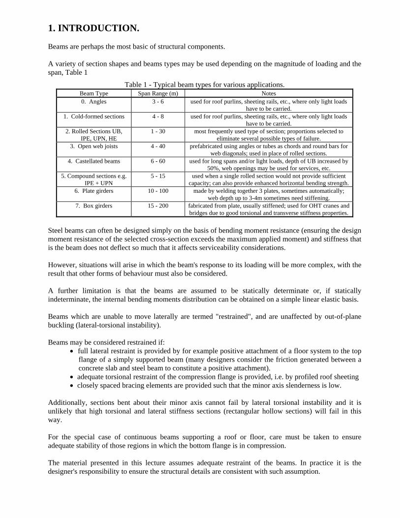
2. MOMENT RESISTANCE. For a doubly symmetrical section or a singly symmetrical section bent about the axis of symmetry, the basic theory of bending, assuming elastic behaviour, gives the distribution of bending stress shown in Figure 1.
Figure 1 - Longitudinal stress distribution for bending about an axis of symmetry (elastic theory).
Since the maximum stress σmax is given by:
( )I
dM 2max =σ (1)
where M is the moment at cross-section under consideration; d is the overall depth of section; I is the second moment of area about the neutral axis (line of zero strain). Limiting this to a fraction of the material yield stress gives a design condition of the form:
W ≥ M/fd (2)
Where: ( )2dIW = and fd is the limiting normal bending stress.
When M is taken as the moment produced by the working loads, this approach to design is termed 'elastic' or 'permissible stress' designs and is the method traditionally used in many existing codes of practice. In more modern Limit States codes fd is taken as the material strength fy possibly divided by a suitable material factor γM and M is taken as the moment due to the factored loads i.e. the working loads suitably increased so as to provide a margin of safety in the design. Equation (2), in this case, represents the condition of first yield. Values of W for the standard range of sections are available in tables of section properties.
Selection of a suitable beam therefore comes down to:
1. Determination of the maximum moment in the beam. 2. Extraction of the appropriate value of fd from a suitable code. 3. Selection of a section with an adequate value of W subject to considerations of minimum weight,
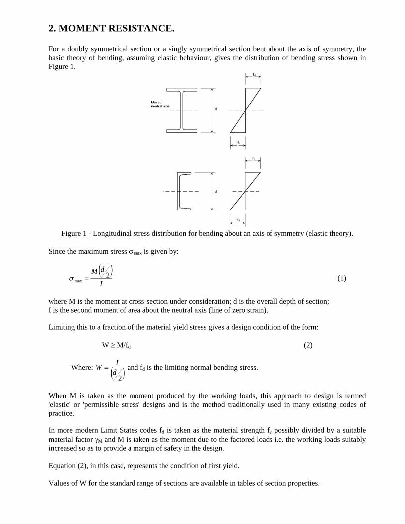
depth of section, rationalisation of sizes throughout the structure, etc... Clearly, sections for which the majority of the material is located as far away as possible from the neutral axis will tend to be the most efficient in elastic bending. Figure 2 gives some quantitative idea of this for some of the more common structural shapes. I-sections are most often chosen for beams because of their structural efficiency; being open sections they can also be connected to adjacent parts of the structure without undue difficulty.
Figure 2 – Relative Section properties for bending of different cross section shapes.
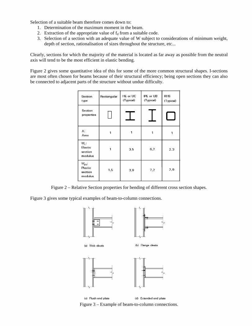
Figure 3 gives some typical examples of beam-to-column connections.
Figure 3 – Example of beam-to-column connections.
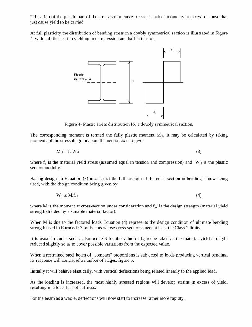
Utilisation of the plastic part of the stress-strain curve for steel enables moments in excess of those that just cause yield to be carried. At full plasticity the distribution of bending stress in a doubly symmetrical section is illustrated in Figure 4, with half the section yielding in compression and half in tension.
Figure 4- Plastic stress distribution for a doubly symmetrical section.
The corresponding moment is termed the fully plastic moment Mpl. It may be calculated by taking moments of the stress diagram about the neutral axis to give:
Mpl = fy Wpl (3) where fy is the material yield stress (assumed equal in tension and compression) and Wpl is the plastic section modulus. Basing design on Equation (3) means that the full strength of the cross-section in bending is now being used, with the design condition being given by:
Wpl ≥ M/fyd (4) where M is the moment at cross-section under consideration and fyd is the design strength (material yield strength divided by a suitable material factor). When M is due to the factored loads Equation (4) represents the design condition of ultimate bending strength used in Eurocode 3 for beams whose cross-sections meet at least the Class 2 limits. It is usual in codes such as Eurocode 3 for the value of fyd to be taken as the material yield strength, reduced slightly so as to cover possible variations from the expected value. When a restrained steel beam of "compact" proportions is subjected to loads producing vertical bending, its response will consist of a number of stages, figure 5. Initially it will behave elastically, with vertical deflections being related linearly to the applied load. As the loading is increased, the most highly stressed regions will develop strains in excess of yield, resulting in a local loss of stiffness. For the beam as a whole, deflections will now start to increase rather more rapidly.
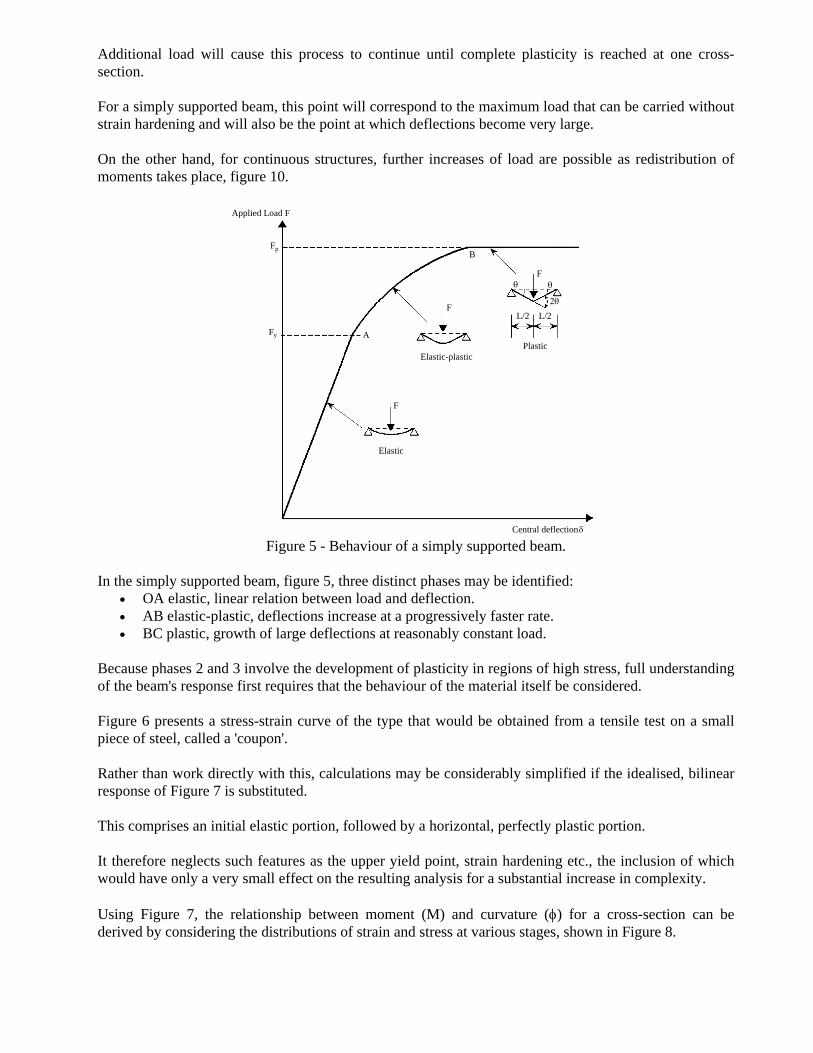
Additional load will cause this process to continue until complete plasticity is reached at one cross-section. For a simply supported beam, this point will correspond to the maximum load that can be carried without strain hardening and will also be the point at which deflections become very large. On the other hand, for continuous structures, further increases of load are possible as redistribution of moments takes place, figure 10.
A
B
F
F
F
L/2 L/2
Applied Load F
Fp
Fy
Central deflectionδ
θ θ
2θ
PlasticElastic-plastic
Elastic
Figure 5 - Behaviour of a simply supported beam.
In the simply supported beam, figure 5, three distinct phases may be identified:
• OA elastic, linear relation between load and deflection. • AB elastic-plastic, deflections increase at a progressively faster rate. • BC plastic, growth of large deflections at reasonably constant load.
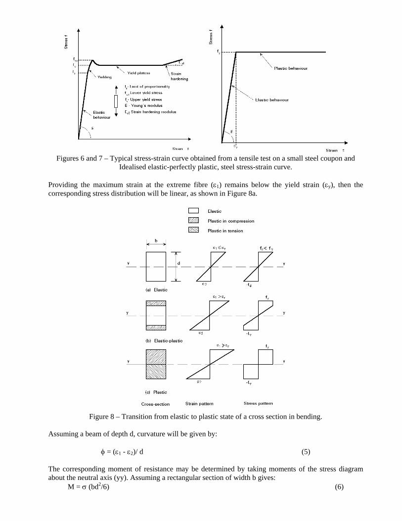
Because phases 2 and 3 involve the development of plasticity in regions of high stress, full understanding of the beam's response first requires that the behaviour of the material itself be considered. Figure 6 presents a stress-strain curve of the type that would be obtained from a tensile test on a small piece of steel, called a 'coupon'. Rather than work directly with this, calculations may be considerably simplified if the idealised, bilinear response of Figure 7 is substituted. This comprises an initial elastic portion, followed by a horizontal, perfectly plastic portion. It therefore neglects such features as the upper yield point, strain hardening etc., the inclusion of which would have only a very small effect on the resulting analysis for a substantial increase in complexity. Using Figure 7, the relationship between moment (M) and curvature (φ) for a cross-section can be derived by considering the distributions of strain and stress at various stages, shown in Figure 8.
Figures 6 and 7 – Typical stress-strain curve obtained from a tensile test on a small steel coupon and
Idealised elastic-perfectly plastic, steel stress-strain curve. Providing the maximum strain at the extreme fibre (ε1) remains below the yield strain (εy), then the corresponding stress distribution will be linear, as shown in Figure 8a.
Figure 8 – Transition from elastic to plastic state of a cross section in bending.
Assuming a beam of depth d, curvature will be given by:
φ = (ε1 - ε2)/ d (5) The corresponding moment of resistance may be determined by taking moments of the stress diagram about the neutral axis (yy). Assuming a rectangular section of width b gives:
M = σ (bd2/6) (6)
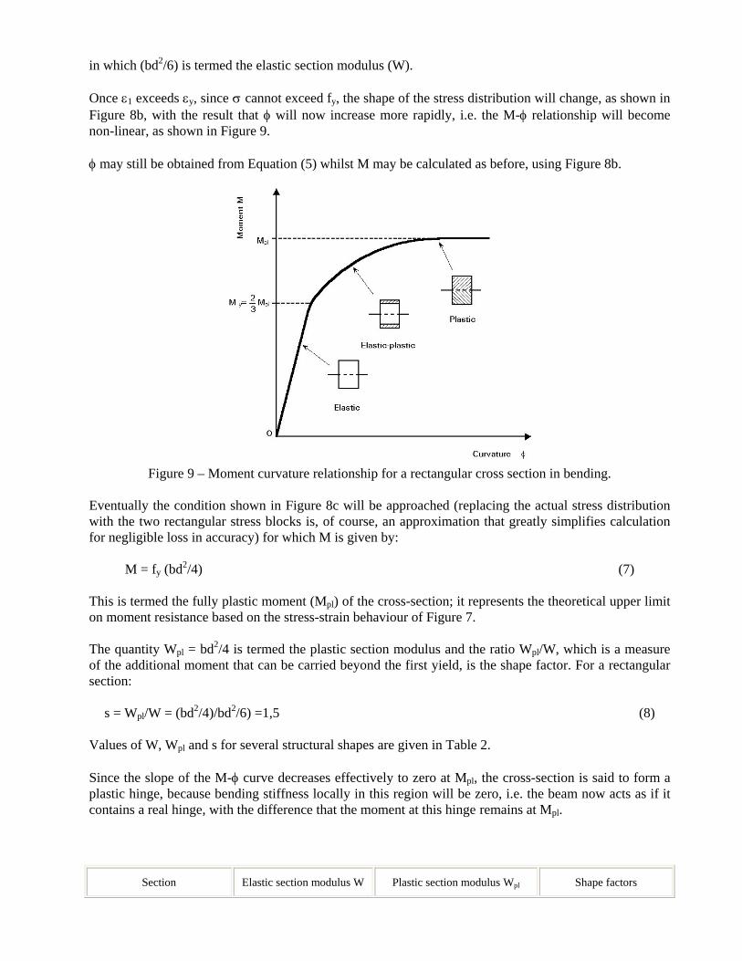
in which (bd2/6) is termed the elastic section modulus (W). Once ε1 exceeds εy, since σ cannot exceed fy, the shape of the stress distribution will change, as shown in Figure 8b, with the result that φ will now increase more rapidly, i.e. the M-φ relationship will become non-linear, as shown in Figure 9. φ may still be obtained from Equation (5) whilst M may be calculated as before, using Figure 8b.
Figure 9 – Moment curvature relationship for a rectangular cross section in bending.
Eventually the condition shown in Figure 8c will be approached (replacing the actual stress distribution with the two rectangular stress blocks is, of course, an approximation that greatly simplifies calculation for negligible loss in accuracy) for which M is given by:
M = fy (bd2/4) (7) This is termed the fully plastic moment (Mpl) of the cross-section; it represents the theoretical upper limit on moment resistance based on the stress-strain behaviour of Figure 7. The quantity Wpl = bd2/4 is termed the plastic section modulus and the ratio Wpl/W, which is a measure of the additional moment that can be carried beyond the first yield, is the shape factor. For a rectangular section:
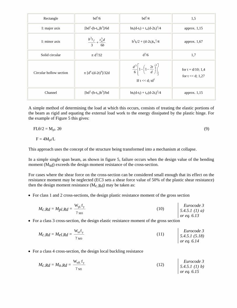
s = Wpl/W = (bd2/4)/bd2/6) =1,5 (8) Values of W, Wpl and s for several structural shapes are given in Table 2. Since the slope of the M-φ curve decreases effectively to zero at Mpl, the cross-section is said to form a plastic hinge, because bending stiffness locally in this region will be zero, i.e. the beam now acts as if it contains a real hinge, with the difference that the moment at this hinge remains at Mpl.
A simple method of determining the load at which this occurs, consists of treating the elastic portions of the beam as rigid and equating the external load work to the energy dissipated by the plastic hinge. For the example of Figure 5 this gives:
FLθ/2 = Mpl. 2θ (9)
F = 4Mpl/L This approach uses the concept of the structure being transformed into a mechanism at collapse. In a simple single span beam, as shown in figure 5, failure occurs when the design value of the bending moment (Msd) exceeds the design moment resistance of the cross-section. For cases where the shear force on the cross-section can be considered small enough that its effect on the resistance moment may be neglected (EC3 sets a shear force value of 50% of the plastic shear resistance) then the design moment resistance (Mc.Rd) may be taken as: • For class 1 and 2 cross-sections, the design plastic resistance moment of the gross section
Mc.Rd = Mpl.Rd = W fpl y
M
.
γ 0 (10)
Eurocode 3 5.4.5.1 (1) a) or eq. 6.13
• For a class 3 cross-section, the design elastic resistance moment of the gross section
Mc.Rd = Mel.Rd = W fel y
Mγ 0 (11)
Eurocode 3 5.4.5.1 (5.18) or eq. 6.14
• For a class 4 cross-section, the design local buckling resistance
Mc.Rd = Mo.Rd = W feff y
M
.
γ 1 (12)
Eurocode 3 5.4.5.1 (1) b) or eq. 6.15
If bolt holes are located in the tension flange at the critical cross-section it is required to check that the ratio of the net area to gross area of the flange is not so small that the section would rupture on the net section before the gross section yielded. This check is the same as that given for ductile tension members and will be satisfied provided Af.net/Af for the tension flange is not less than 0.81 or 0.88 for flange thickness less than 40mm in S275 and S355
steel respectively ⎟⎟⎠
⎞⎜⎜⎝
⎛≥
0
2
9,0 Mu
My
ft
fnet
ff
AA
γγ
. Eurocode 3 (5.4.5.3) or eq. 6.16
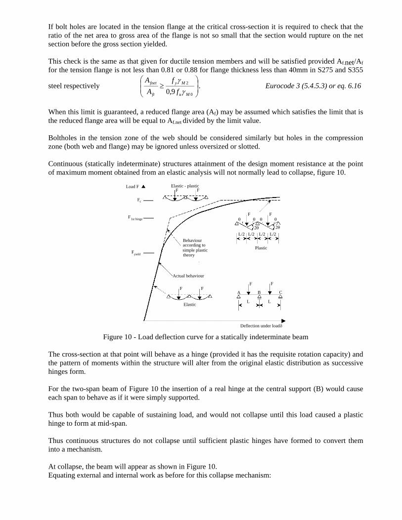
When this limit is guaranteed, a reduced flange area (Af) may be assumed which satisfies the limit that is the reduced flange area will be equal to Af.net divided by the limit value. Boltholes in the tension zone of the web should be considered similarly but holes in the compression zone (both web and flange) may be ignored unless oversized or slotted. Continuous (statically indeterminate) structures attainment of the design moment resistance at the point of maximum moment obtained from an elastic analysis will not normally lead to collapse, figure 10.
Load F Elastic - plasticF F
F F
L/2 L/2 L/2 L/2
Plastic
Behaviouraccording tosimple plastictheory
Actual behaviour
F F
Elastic
A B C
F F
L L
Fc
F1st hinge
Fyield
θ θ θ θ
2θ 2θ
Deflection under loadδ
Figure 10 - Load deflection curve for a statically indeterminate beam The cross-section at that point will behave as a hinge (provided it has the requisite rotation capacity) and the pattern of moments within the structure will alter from the original elastic distribution as successive hinges form. For the two-span beam of Figure 10 the insertion of a real hinge at the central support (B) would cause each span to behave as if it were simply supported. Thus both would be capable of sustaining load, and would not collapse until this load caused a plastic hinge to form at mid-span. Thus continuous structures do not collapse until sufficient plastic hinges have formed to convert them into a mechanism. At collapse, the beam will appear as shown in Figure 10. Equating external and internal work as before for this collapse mechanism:
2FLθ/2 = Mpl (2θ + 2θ + 2θ) (13)
F = 6Mpl/L Figure 10 shows the load-deflection curve for this two-span beam obtained from an elastic-plastic analysis. Each change in slope corresponds to the formation of a plastic hinge that produces progressive "softening" of the structure. Collapse occurs at an applied load given by Equation (13) when sufficient hinges have formed to transform the beam into a mechanism with no inherent stiffness, corresponding to the final horizontal segment of the curve. It is usual, when conducting this type of analysis, to assume that plastic hinges form suddenly; this corresponds to regarding the cross-section as having a unit shape factor, i.e. Wpl = W. Although the elastic-plastic analysis of statically indeterminate beams is quite complex, the determination of the collapse load from considerations of the collapse mechanism for most types of continuous beam and portal frames is relatively straightforward. It should be noted that, in passing from the elastic state corresponding to loads up to Fyield to the plastic state corresponding to the load Fcollapse, the beam of Figure 10 has undergone a redistribution of moment. Thus the shape of the plastic moment diagram will differ from that of the elastic moment diagram. In this case the former will correspond to Mpl at all three plastic hinges, whilst the latter will have a maximum at the central support. This is plastic design and requires a cross-section that can rotate whilst sustaining the plastic resistance moment i.e. a class 1 section is necessary. 2.1 Bending of I-Sections. Applying the stress-strain curve of Figure 11 to the idealised I-section of Figure 11a bending about the yy axis, in which half of the area is assumed to be concentrated at the mid-depth of each flange, leads to the bilinear M-φ curve of Figure 12.
Figure 11 – Sections.
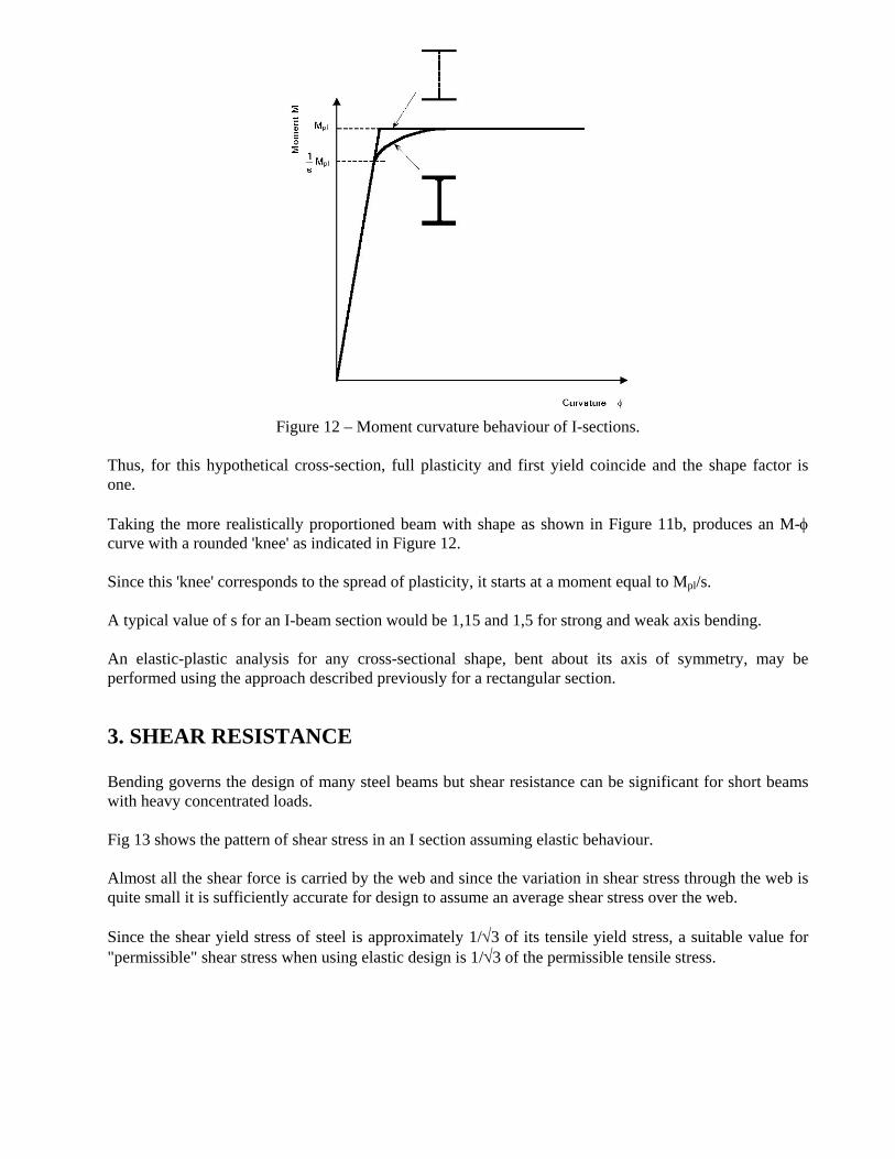
Figure 12 – Moment curvature behaviour of I-sections.
Thus, for this hypothetical cross-section, full plasticity and first yield coincide and the shape factor is one. Taking the more realistically proportioned beam with shape as shown in Figure 11b, produces an M-φ curve with a rounded 'knee' as indicated in Figure 12. Since this 'knee' corresponds to the spread of plasticity, it starts at a moment equal to Mpl/s. A typical value of s for an I-beam section would be 1,15 and 1,5 for strong and weak axis bending. An elastic-plastic analysis for any cross-sectional shape, bent about its axis of symmetry, may be performed using the approach described previously for a rectangular section.
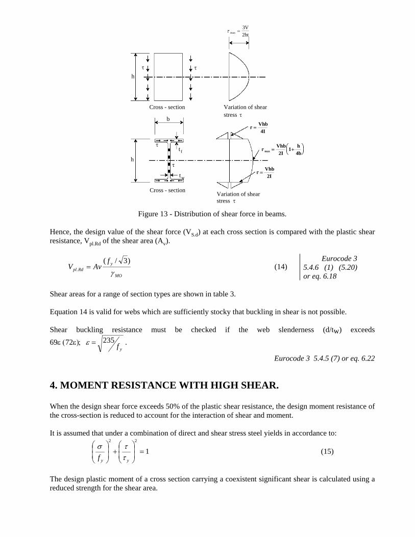
3. SHEAR RESISTANCE Bending governs the design of many steel beams but shear resistance can be significant for short beams with heavy concentrated loads. Fig 13 shows the pattern of shear stress in an I section assuming elastic behaviour. Almost all the shear force is carried by the web and since the variation in shear stress through the web is quite small it is sufficiently accurate for design to assume an average shear stress over the web. Since the shear yield stress of steel is approximately 1/√3 of its tensile yield stress, a suitable value for "permissible" shear stress when using elastic design is 1/√3 of the permissible tensile stress.
τ maxVht
=32
h
Cross - section
b
h
Cross - section
τ τ
Variation of shearstress τ
τ
τ
Variation of shearstress τ
t f
tw
τ =Vhb4I
τ maxVhb2I
h4b
= +⎛⎝⎜
⎞⎠⎟
1
τ =Vhb2I
Figure 13 - Distribution of shear force in beams.
Hence, the design value of the shear force (VS.d) at each cross section is compared with the plastic shear resistance, Vpl.Rd of the shear area (Av).
MO
yRdpl
fAvV
γ)3/(
. = (14) Eurocode 3
5.4.6 (1) (5.20) or eq. 6.18
Shear areas for a range of section types are shown in table 3. Equation 14 is valid for webs which are sufficiently stocky that buckling in shear is not possible. Shear buckling resistance must be checked if the web slenderness (d/tw) exceeds
69ε (72ε); yf
235=ε .
Eurocode 3 5.4.5 (7) or eq. 6.22
4. MOMENT RESISTANCE WITH HIGH SHEAR. When the design shear force exceeds 50% of the plastic shear resistance, the design moment resistance of the cross-section is reduced to account for the interaction of shear and moment. It is assumed that under a combination of direct and shear stress steel yields in accordance to:
122
=⎟⎟⎠
⎞⎜⎜⎝
⎛+⎟
⎟⎠
⎞⎜⎜⎝
⎛
yyf ττσ (15)
The design plastic moment of a cross section carrying a coexistent significant shear is calculated using a reduced strength for the shear area.
This reduced strength is dependent on the ratio of the shear load to shear capacity by the relationship, 2
.
12⎟⎟⎠
⎞⎜⎜⎝
⎛−=
Rdpl
sd
VVρ (16)
Eurocode 3 eq. 6.29 and the reduced strength is (1-ρ)fy for the shear area. For an I beam or H section bent about its major axis this leads to the reduced design plastic resistance moment in the presence of shear (Mv.Rd).
Mo
y
w
vplRdv
ftAWM
γρ
⎥⎦
⎤⎢⎣
⎡−=
4
2
. (17) Eurocode 3 5.4.7 (3)a (5.22) or eq. 6.30
Table 3 - Shear Areas Av for Typical Sections.
Rolled Load parallel to web 1,04 h tw * htw
I and H sections Fabricated Load parallel to web (h - 2tf) tw htw
Load parallel to flanges A- (h - 2tf) tw *
d
tw
Rolled channel sections Load parallel to web 1,04 h tw * htw
Rolled angle sections Load parallel to longer leg h t
t
d
w
Rolled rectangular hollow Load parallel to depth Ah/(b + h) ** h
b
sections of uniform thickness Load parallel to breadth Ah/(b + h) **
h
b
Circular hollow sections and tubes of uniform thickness 0,6 A **
Plates and solid bars A **
* This is an approximate formula. More accurate values of Av for rolled sections can be determined from:
• for I and H sections: Av = A - 2btf + (tw + 2r) tf • for channel sections: Av = A - 2btf + (tw + 2r) tf
It is convenient to note that 1,04 / √3 = 0,60 and so for a rolled I, H or channel section: Vpl.Rd = 0,60 h tw fy / γM0
** A is the total cross-sectional area
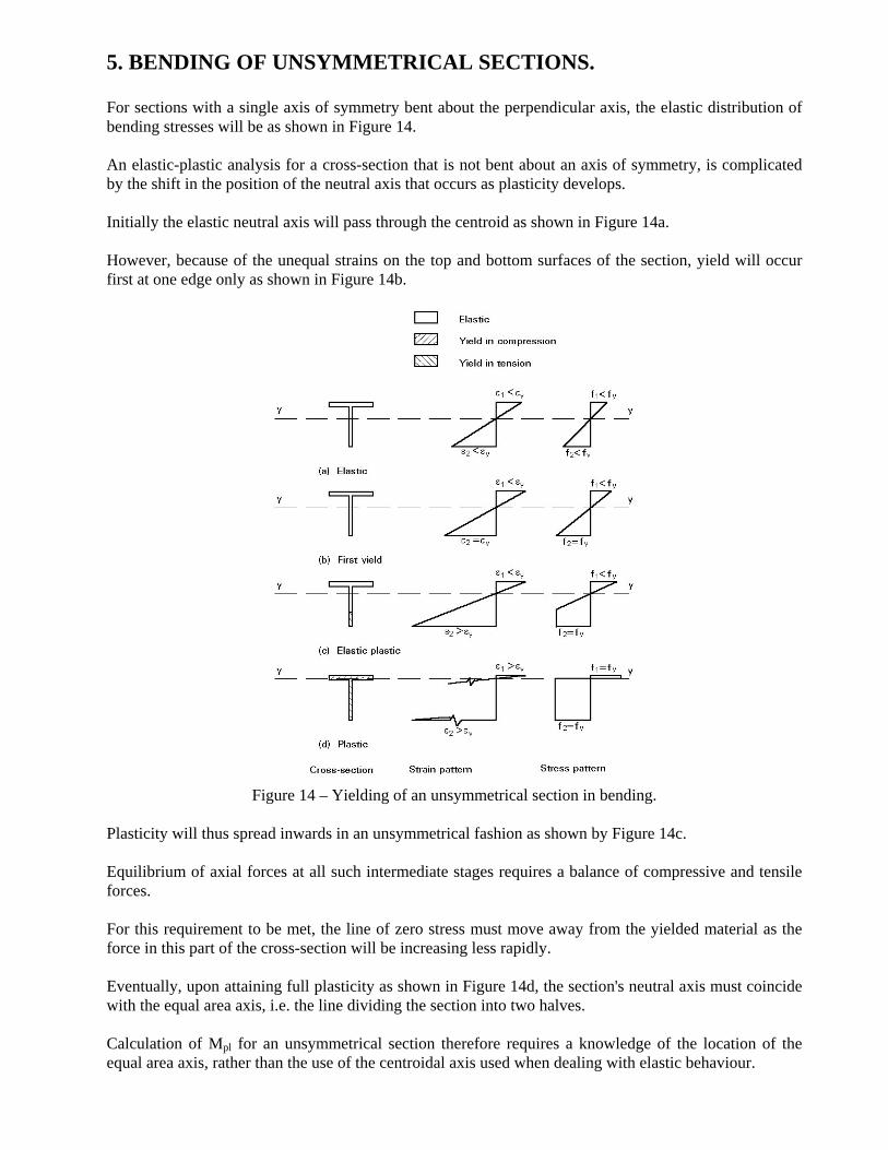
5. BENDING OF UNSYMMETRICAL SECTIONS. For sections with a single axis of symmetry bent about the perpendicular axis, the elastic distribution of bending stresses will be as shown in Figure 14. An elastic-plastic analysis for a cross-section that is not bent about an axis of symmetry, is complicated by the shift in the position of the neutral axis that occurs as plasticity develops. Initially the elastic neutral axis will pass through the centroid as shown in Figure 14a. However, because of the unequal strains on the top and bottom surfaces of the section, yield will occur first at one edge only as shown in Figure 14b.
Figure 14 – Yielding of an unsymmetrical section in bending.
Plasticity will thus spread inwards in an unsymmetrical fashion as shown by Figure 14c. Equilibrium of axial forces at all such intermediate stages requires a balance of compressive and tensile forces. For this requirement to be met, the line of zero stress must move away from the yielded material as the force in this part of the cross-section will be increasing less rapidly. Eventually, upon attaining full plasticity as shown in Figure 14d, the section's neutral axis must coincide with the equal area axis, i.e. the line dividing the section into two halves. Calculation of Mpl for an unsymmetrical section therefore requires a knowledge of the location of the equal area axis, rather than the use of the centroidal axis used when dealing with elastic behaviour.
Singly symmetrical sections have two different values of the elastic section modulus for the two faces, because of the different distances of the latter from the elastic neutral axis. However, such sections possess a single value of plastic section modulus equal to Mpl/fy. They will therefore have two values of shape factor depending on which of the faces is under consideration. For extreme sections i.e. as tees, these may differ quite widely with one value actually being less than unity. Although this does not affect the basic relationship between My and Mpl for the section, it can be a source of confusion in situations which require the specific consideration of yield in compression (or tension).
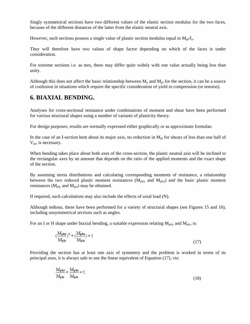
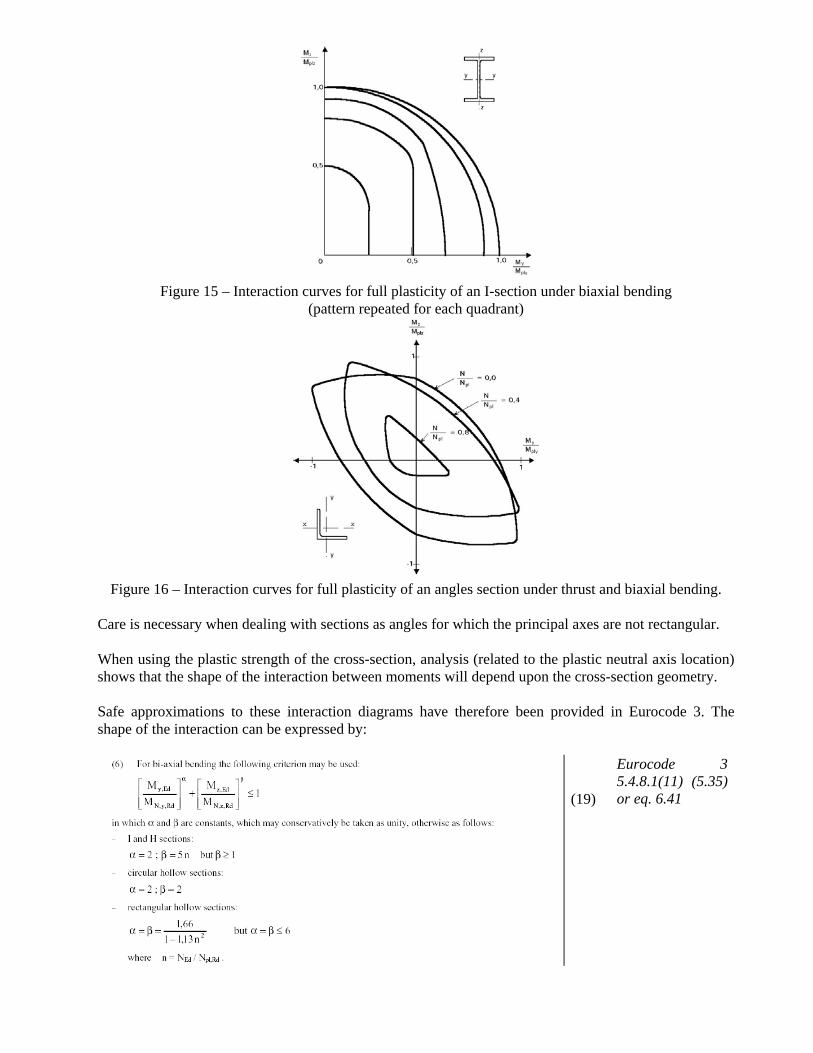
6. BIAXIAL BENDING. Analyses for cross-sectional resistance under combinations of moment and shear have been performed for various structural shapes using a number of variants of plasticity theory. For design purposes, results are normally expressed either graphically or as approximate formulae. In the case of an I-section bent about its major axis, no reduction in Mpl for shears of less than one half of Vpw is necessary. When bending takes place about both axes of the cross-section, the plastic neutral axis will be inclined to the rectangular axes by an amount that depends on the ratio of the applied moments and the exact shape of the section. By assuming stress distributions and calculating corresponding moments of resistance, a relationship between the two reduced plastic moment resistances (Mplry and Mplrz) and the basic plastic moment resistances (Mply and Mplz) may be obtained. If required, such calculations may also include the effects of axial load (N). Although tedious, these have been performed for a variety of structural shapes (see Figures 15 and 16), including unsymmetrical sections such as angles. For an I or H shape under biaxial bending, a suitable expression relating Mplry and Mplrz is:
(17) Providing the section has at least one axis of symmetry and the problem is worked in terms of its principal axes, it is always safe to use the linear equivalent of Equation (17), viz:
(18)
Figure 15 – Interaction curves for full plasticity of an I-section under biaxial bending
(pattern repeated for each quadrant)
Figure 16 – Interaction curves for full plasticity of an angles section under thrust and biaxial bending.
Care is necessary when dealing with sections as angles for which the principal axes are not rectangular. When using the plastic strength of the cross-section, analysis (related to the plastic neutral axis location) shows that the shape of the interaction between moments will depend upon the cross-section geometry. Safe approximations to these interaction diagrams have therefore been provided in Eurocode 3. The shape of the interaction can be expressed by:
(19)
Eurocode 3 5.4.8.1(11) (5.35) or eq. 6.41
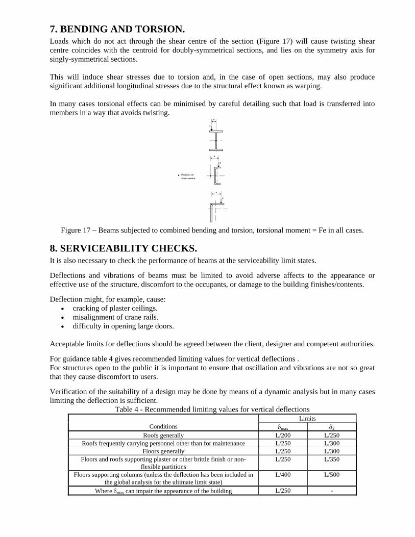
7. BENDING AND TORSION. Loads which do not act through the shear centre of the section (Figure 17) will cause twisting shear centre coincides with the centroid for doubly-symmetrical sections, and lies on the symmetry axis for singly-symmetrical sections. This will induce shear stresses due to torsion and, in the case of open sections, may also produce significant additional longitudinal stresses due to the structural effect known as warping. In many cases torsional effects can be minimised by careful detailing such that load is transferred into members in a way that avoids twisting.
Figure 17 – Beams subjected to combined bending and torsion, torsional moment = Fe in all cases.
8. SERVICEABILITY CHECKS. It is also necessary to check the performance of beams at the serviceability limit states.
Deflections and vibrations of beams must be limited to avoid adverse affects to the appearance or effective use of the structure, discomfort to the occupants, or damage to the building finishes/contents.
Deflection might, for example, cause: • cracking of plaster ceilings. • misalignment of crane rails. • difficulty in opening large doors.
Acceptable limits for deflections should be agreed between the client, designer and competent authorities.
For guidance table 4 gives recommended limiting values for vertical deflections . For structures open to the public it is important to ensure that oscillation and vibrations are not so great that they cause discomfort to users.
Verification of the suitability of a design may be done by means of a dynamic analysis but in many cases limiting the deflection is sufficient.
Table 4 - Recommended limiting values for vertical deflections Limits
Conditions δmax δ2 Roofs generally L/200 L/250
Roofs frequently carrying personnel other than for maintenance L/250 L/300 Floors generally L/250 L/300
Floors and roofs supporting plaster or other brittle finish or non-flexible partitions
L/250 L/350
Floors supporting columns (unless the deflection has been included in the global analysis for the ultimate limit state)
L/400 L/500
Where δmax can impair the appearance of the building L/250 -
Floors in dwellings and offices should have a lowest natural frequency not less than 3 cycles/second. This condition will be satisfied if the instantaneous total deflection (table 3) is less than 28mm. For floors in gymnasia or dance halls, the lowest natural frequency should not be less than 5 cycles/second - a deflection limit of 10mm would satisfy this limit. Flat roofs (slopes < 5°) are vulnerable to pounding if the roof deflects such that pools of water may form.
9. CONCLUDING SUMMARY. • The main design requirement for restrained beams is the provision of adequate bending strength. • Section modulus, either elastic or plastic depending upon the design philosophy adopted, is the most
appropriate property for use in selecting a suitable section. • Design moment resistances for cross-sections depend upon section classification. • Providing instability effects do not occur, steel beams can withstand moments in excess of those that
just cause yield. Stress redistribution over the cross-section enables the fully plastic pattern of bending stresses to develop, for which the moment of resistance is the full plastic moment, Mpl.
• Statically indeterminate beams only collapse when sufficient regions of full local plasticity, termed
"plastic hinges" have developed to convert the "structure" into a mechanism. • The value of Mpl is given by the product of yield stress (fy) and a geometrical property of the cross-
section termed the "plastic section modulus" - Wpl; the ratio Wpl/W is called the "shape factor". • Holes in the tension zone of a beam may in some cases cause a reduction in the movement resistance. • Shear capacity and deflection must also be checked in simple beam design. • Co-existent shear forces below 50% of the plastic shear resistance do not affect moment resistance.
Where high shear forces occur, the shear area contribution to moment resistance should be deducted. • Serviceability limits on deflection or vibration may control the design.
ADDITIONAL READING. 1. Dowling, P.J., Owens, G.W. and Knowles, P., "Structural Steel Design", Butterworths, 1988. 2. Salmon, C. G. Johnson, J. E., "Steel Structures - Design and Behaviour", Harper & Row, 1980. 3. Ballio, G., Mazzolani, F., "Theory and Design of Steel Structures", Chapman & Hall, 1983. 4. McGinley, TJ. Ang, TC, "Structural Steelwork Design to Limit State Theory", Butterworths, 1987