AIWXSIS OF A NUClXAR-- UQUID-&WJ!AL WCTED-FAN CYCIB
By F. E. Rom and W. W. Wachtl ["I An analysis of a nuclear-powered liquid-metal dtucted-fan cycle is
presented f o r a range of engine operating conditions at f l i g h t Mach numbers of 0.9 and 1.5 and a t an al t i tude of 50,000 fee t .
The compressor and f an pressure rat ios , heat-exchanger i n l e t Mach umber, and duct-outlet temperature are optimized f o r given heat- exchanger wall temperatures t o give maximum thrus t per engine-plus- exchanger weight, which i n turn resul ts i n minimum gross weight.
Airplane gross weight and reactor heat re lease a re presented fo r a range of the sum of reactor, shield, payload, and auxi l iary weight, and fo r typ ica l values of airplane l i f t -drag r a t i o and structure-to- gross weight r a t io s . For a heat-exchanger effect ive w a l l temperature of 18000 R, sum of the shield, reactor, payload, and auxi l iary weight of 150,000 pounds, and structure-to-gross weight r a t i o of 0.35, the airplane gross weight i s 288,000 pounds fo r a f l i g h t Mach number of 0.9. The reactor maximum wall temperature i s 1858' R. For a f l i g h t Mach number of 1.5, the airplane gross weight is 367,000 pounds and the reactor maximum wall temperature i s 2080° R f o r the same assumptions. The e f fec t of a l t i t ude on gross weight and reactor heat release is a lso shown.
The required gross weight and reactor heat re lease f o r the ducted- f an cycle is compared with tha t required f o r the turbojet cycle. The gross weight f o r both cycles is approximately the same. The reactor heat releases required fo r the ducted fan a re about 10 and 20 percent higher than f o r the turbojet cycle for f l i g h t Mach numbers of 0.9 and 1.5, respectively.
INTRODUCTION
A general study of nuclear-powered a i r c r a f t propulsion cycles i s being carr ied out at the NACA Lewis laboratory. Several reports giving the r e su l t s of previous studies have been issued. References 1 and 2 discuss the direct-air cycle while reference 3 i s a preliminary compari- son of the d i rec t -a i r , liquid-metal turbojet, and helium compressor-jet cycles. Reference 4 presents a detailed anal metal
D DATA ?!T CONTAIFS RESTRICTED DATA X THE ATOMIC ENERGY ACf OP NhMITTAL OR DISCLOSURE OF S IN ANY MANNER TO AN UlYI OBLIIIIIIK p-N is P ~ o H x B r r m .
Restriction/Classification Cancelled
Restriction/Classification Cancelled
Restriction/Classification Cancelled
NACA RM E52G16
turbojet cycle. The liquid-metal turbine-propeller cycle is analyzed *r
in reference 5. The present report extends these studies by considering the nuclear-powered liquid-metal ducted-fan cycle.
8
The chemically fueled ducted-fan cycle is studied in reference 6 as 0) UI
a dual-purpose power plant where the cycle showed high-speed design-point 4 4
performance comparable with that of the turbojet but superior low-speed off-design performance. According to these results, the ducted fan may also have possibilities as a nuclear-powered high-performance engine with good low-speed off-design characteristics. The analysis presented herein considers the high-performance design-point nuclear-powered ducted-fan cycle. In this cycle the shaft power output of a compressor-turbine combination (defined herein as basic engine) powered with a nuclear heat source is used to drive a ducted fan. The duct air is heated by the same nuclear heat source.
Engine performance is emphasized inasmuch as reference 4 indicated that for fixed values of airplane lift-drag ratio, structure-to-gross- weight ratio, and the sum of shield, reactor, payload, and auxiliary weights, the maximum engine net thrust per pound of engine-plus-exchanger weight gives the minimum-gross-weight airplane. However, the engine data are presented in such a manner that the gross weight, reactor heat release, and reactor wall temperature can readily be found.
The results are presented for flight Mach numbers of 0.9 to 1.5 at an altitude of 50,000 feet. The effect of flight altitude on optimum engine design-point airplane performance is also shown. The engine para- meters considered are turbine-inlet temperature, basic-engine heat- exchanger effective wall temperature, basic-engine compressor pressure ratio, fan pressure ratio, duct heat-exchanger inlet Mach number, duct heat-exchanger effective wall temperature, and duct-outlet air temperature. The fan pressure ratio, basic-engine compressor pressure ratio, duct heat- exchanger inlet Mach number, and duct-outlet air temperature are optimized for maximum thrust per engine-plus-heat-exchanger weight for a range of duct heat-exchanger effective wall temperatures. In general, a fixed value is assumed for the basic-engine heat-exchanger inlet Mach number and for the effective wall temperature. The effect of changing the basic-engine heat-exchanger effective wall temperature is investigated by considering the case where the basic-engine heat-exchanger effective wall temperature is equal to the variable duct heat-exchanger effective wall temperatures.
The liquid-metal ducted-fan cycle is compared with the liquid-metal + r l r ; h n i a + n-ml n 9- - - - ,+ZL l - ,,,.-Lr --- L- -I---- LL- Y- Y V J - Y - J LAL I V I L V U ~ ~ C I I U I G ~ ~ P L U I ~ ~ ~ I U L L ~ CIU DLLUW UIC; relG.tP*re desf GZ- point performances of the two cycles.
SYMBOLS
The following symbols a re used in t h i s report:
area, sq f t
velocity coefficient
specific heat a t constant pressure, ~ t u / ( l b ) -(*)
drag, l b
hydraulic diameter, f t
thrust , l b
f r e e flow factor (flow area divided by t o t a l area)
acceleration of gravity, 32.2 ft /sec 2
enthalpy, ~ t u / l b
mechanical equivalent of heat, 778 f t -1b f ~ t u
thermal conductivity, (Btu) ( f t )/(set) (sq f t ) (%)
l i f t , l b
length, f t
Mach number
t o t a l pressure, lb/sq f t
s t a t i c pressure, lb/sq f t
reactor heat release, Btu/sec
t o t a l temperature, OR
s t a t i c temperature, %
over-all heat t ransfer coefficient, ~ t u / ( s e c ) (sq f t ) (9)
velocity, f t /sec
weight, l b
a i r flow, lb/sec
NACA RM E52G16
r a t i o of spec i f i c heats
enthalpy change, ~ t u / l b
difference between l o c a l reac tor w a l l and l o c a l coolant temperature, OR
difference between basic-engine heat-exchanger e f f ec t i ve w a l l and maximum coolant temperature, OF
' r a t io of t o t a l pressure t o NACA standard sea l e v e l pressure
r a t i o of t o t a l temperature t o NACA standard sea l e v e l temperature
density, lb/cu f t
Subscripts
a t o t a l air flow
c compressor
d duct
e basic engine
F f r o n t a l
f fan
Q gross
3 Je t
K sum of reactor , shie ld , payload, and aux i l i a ry
2 l i qu id
m. reactor maximum w a l l
N nacel le
r reac tor
s s t ruc ture
NACA RM E52G16
sum of compressor, turbine, shell, fan, basic-engine heat exchanger, and duct heat exchanger
turbine
basic-engine heat-exchanger effective wall
duct heat -exchanger effective wall
heat exchanger
free stream
fan inlet
2 fan outlet or compressor inlet
3 compressor outlet
3 ' duct heat-exchanger outlet
4 turbine inlet
5 turbine outlet
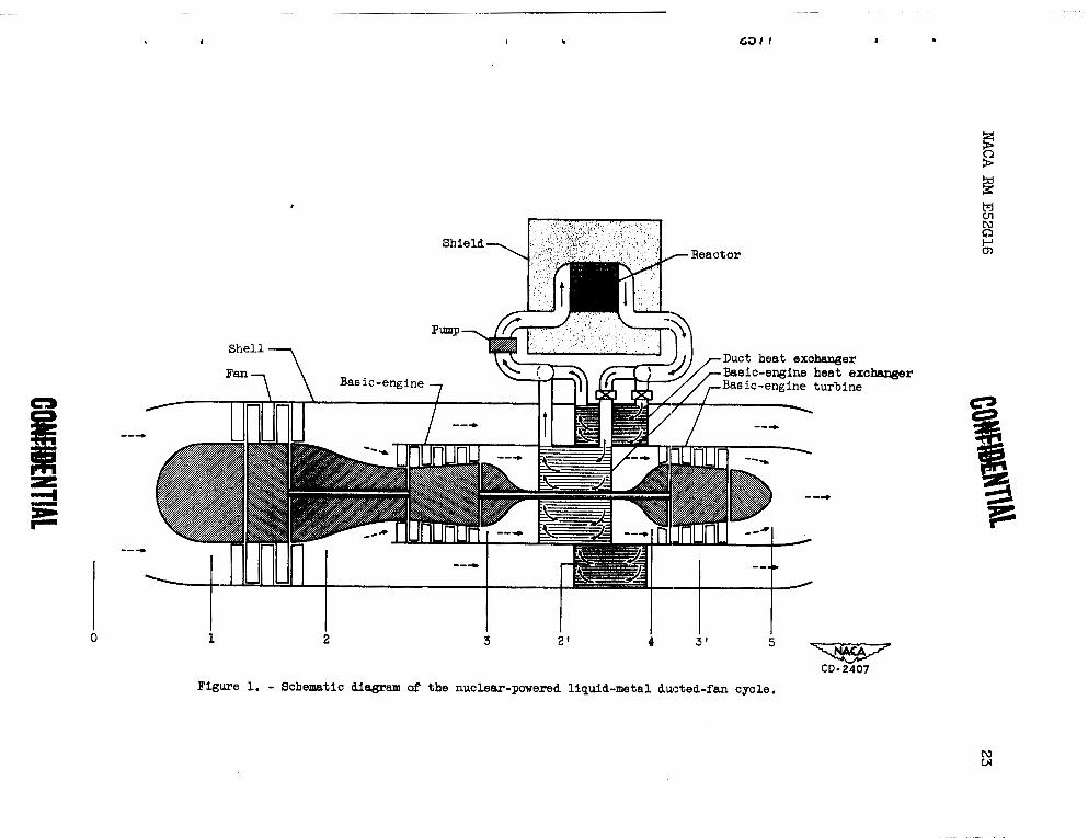
The liquid-metal ducted-fan cycle is shown schematically in figure 1. The engine consists of a compressor-turbine combination (referred to as the basic engine) which drives a ducted low-pressure- ratio compressor (fan). The air leaving the fan is divided between the basic engine and the duct portion of the cycle so as to utilize completely the shaft power of the basic engine. Lithium is used to tranport the heat from the reactor to the basic-engine and duct heat exchangers. The propulsive thrust is supplied by the exhaust jets issuing from the nozzle of both the basic engine and the duct. The stations used in the analysis of the cycle are also shown in figure 1.
ASSUMPTIONS
Engine component efficiencies. - The engine component efficiencies assumed for the analysis are as follows:
The in le t -d i f fuse r total-pressure-recovery r a t i o s pl/pO, which a r e * t h e same as used i n reference 4, a r e 0.965 and 0.950 a t Mach numbers of 0.9 and 1.5, respectively.
a
Tail-pipe pressure r a t i o P ~ / ~ ~ . - I n computations of t he shaf t work N m
and j e t th rus t of t he bas ic engine, t h e basic-engine P ~ / ~ ~ i s assumed 4 4
t o be equal t o the ram pressure r a t i o pl/pOI According t o reference 7 t h i s assumption gives c lose t o the optimum d i v i s i o n of power between t he j e t and propeller f o r a turbine-propeller engine. Inasmuch as t h e ducted- f a n engine has a lower propulsive e f f i c iency than the turbine-propel ler because of i t s lower a i r flow, t he optimum p51P0 i s expected t o be
s l i g h t l y higher than f o r the turbine-propeller . I n reference 7, however, it i s shown t h a t t o t a l t h ru s t i s not sens i t ive t o P ~ / ~ ~ on e i t h e r s i de
of the optimum f o r t he turbine-propeller cycle. Preliminary ca lcu la t ions on the ducted-fan cycle indicated t he same s m a l l e f fec t . \ Consequently t he assumption t h a t P ~ / ~ ~ i s equal t o P ~ / ~ ~ i s considered applicable t o the ducted fan. Both the duct and basic-engine exhaust j e t s a r e assumed t o discharge t o atmospheric s t a t i c pressure.
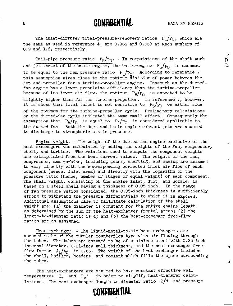
Engine weight. - The weight of the ducted-fan engine exclusive of the . heat exchangers was calcula ted by adding t he weights of t he fan, compressor, she l l , and turbine . The r e l a t i o n s used t o compute the component weights a r e extrapolated from the be s t current values. The weights of t he fan, compressor, and turbine, including gears, shaft ing, and casing a r e assumed 4
t o vary d i r ec t l y with the corresponding corrected i n l e t a i r flow of each component (hence, i n l e t a rea ) and d i r e c t l y with t he logarithm of the pressure r a t i o (hence, number of stages of equal weight) of each component. The s h e l l weight, consis t ing of the engine i n l e t , duct, and nozzle, i s based on a s t e e l s h e l l having a thickness of 0.05 inch. In the range of f a n pressure r a t i o s considered, t he 0.05-inch thickness i s s u f f i c i e n t l y s t rong t o withstand the pressure d i f f e r e n t i a l s t o which it i s exposed. Additional assumptions made t o f a c i l i t a t e ca lcu la t ion of the s h e l l weight are: (1) the diameter i s constant f o r the e n t i r e engine length, a s determined by the sum of the heat-exchanger f r o n t a l areas; ( 2 ) t he length-to-diameter r a t i o i s 4; and (3) t he heat-exchanger free-flow r a t i o s a re a s assigned.
Heat exchanger. - The l iquid-metal- to-air heat exchangers a r e assumed t o be of t he tubular counterflow type with air flowing through t he tubes. The tubes a r e assumed t o be of s t a i n l e s s s t e e l with 0.25-inch i n t e r n a l diameter, 0.01-inch wal l thickness, and the heat-exchanger f r e e - 7
flow fac to r & /A+ i s 0.65. The weight of t he heat exchanger includes the she l l , b a f f l e s , headers, and coolant which f i l l s t he space surrounding t he tubes. a
The heat-exchangers a r e assumed t o have constant e f f ec t i ve w a l l temperatures Tw and TWt i n order t o simplify heat - t ransfer calcu- l a t i ons . The heat-exdhanger length-to-diameter r a t i o 2/d and pressure
NACA RM E52G16
.. drop axe computed from t h i s assumption by means of t he char ts presented i n reference 4, which were obtained by the methods given i n reference 8 . Reference 8 calculates pressure drop by a step-by-sbep process which
Y takes i n t o account simultaneous f r i c t i o n and momentum pressure drop. No e r ro r i n 2/d and only a s l i gh t e r ror i n pressure drop r e s u l t s fram assuming a constant effect ive wal l temperature.
Reactor maximum w a l l temperature Tm. - The reactor maximum w a l l N temperature i s calculated frcm the following assumptions: U1 4 ~ 1. The flow leaving the reactor i s divided in to two pa ra l l e l
, flows, one t o each heat exchanger.
2. The power input along the reactor passage i s constant.
3. The basic-ensine heat-exzkizrige~ iiiiet liquid-metal temperature is 50° F higher than Tw f o r a reactor heat re lease Q of 100,000 Btu per second%nd t h i s difference i s d i r ec t ly proportional t o the reactor heat release.
4. The liquid-metal (lithium) velocity i n t he reactor i s 15 f e e t per second.
5. The reactor diameter and length a r e each 2.5 f ee t .
6. The reactor free-flow r a t i o is 0.35.
7. The hydraulic diameter of the reactor flow passages i s 0.25 inch.
8. The heat generated by the reactor i s only tha t required t o power the engines with no aux i l i a r i e s or heat losses.
Reactor, shield, payload, and auxi l iary weights WK. - A range of values from 100,000 t o 200,000 pounds is assumed f o r WK, the sum of the
reactor, shield, payload, and auxil iary weight (pumps, piping, e l e c t r i c a l equipment, e t c ) .
Airplane assumitions. - The structure-to-gross-weight r a t i o wS/Vg of the a i rplane i s assumed t o be 0.35 and 0.25. The airplane design l i f t -d rag r a t i o L/D f o r a. submerged engine in s t a l l a t i on i s assumed t o be 18 f o r a f l i g h t Mach number of 0.9 and 6 and 9 f o r a f l i g h t Mach number of 1.5.
METHODS
It was shown i n reference 4 t ha t optimizing the engine net t h rus t per engine-plus -exchanger weight F,/w~ i s suf f ic ien t t o determine the a i rplane minimum gwss weight f o r f %xed values of L/D, Y ~ / W , , and WK.
NACA RM E52G16
In the present analysis, a similar optimization for maximum F,/w~ is carried out.
Cycle Analysis
Range of variables. - The performance of the ducted-fan cycle with a nuclear heat source is calculated at flight Mach numbers % of 0.9 and 1.5 for an altitude of 50,000 feet. The fan pressure ratio p2/p1 is varied from 1.2 to 5.0 and the compressor pressure ratio p3/p2 is varied from 1.0 to 10.0. In general, Tw is fixed at 2270' R and the turbine-inlet temperature Tq is fixed at 2000° R. However, a special case is considered where Tw is set equal to TW1 to find the effect of lower-temperature operation; Twt is varied from 1600 to 2200' R while Tg' is varied from 1100 to 2000° R. The M2' is varied from 0.12 to 0.24 while the M3 is held constant at 0.15 based on the results of the turbojet cycle of reference 4 which gave 0.15 as close to the optimum value.. In the course of the analysis it was found that a basic engine with M3 n 0.12 gave slightly better engine performance. Therefore this value was used for the case of reduced Tw. *
Calculation of net thrust per pound of air per second F~/w~. - The fan inlet total temperature TI and the total pressure PI are determined for the assumed flight conditions and corresponding diffuser- C
pressure-recovery ratio pl/pO. The enthalpy of the air entering the fan hl and the enthalpy rise through the fan Ahf and through the compressor Ahc are determined from the thermodynamic-property tables and methods presented in reference 9 for the assumed compression efficiencies. The fan-outlet total temperature T2 and total pressure P2 are the same as the duct heat-exchanger inlet temperature T2' and pressure P2', respectively. Similarly, the compressor-outlet tempera- ture T3 and pressure P3 are the same as the basic-engine heat- exchanger inlet temperature and pressure. The heat-exchanger pressure ratios P2 '/pgl and p3/p4 can then be computed from the assumed inlet
Mach numbers, effective wall temperatures, and duct-outlet and turbine- inlet temperature from the figures presented in reference 4.
The turbine pressure ratio can be found as follows (assuming that P1 = p5):
By use of the thermodynamic charts in reference 9, P~/P,-, T4, h5, and T5 can be found. The turbine enthalpy drop Aht is then determined.
NACA RM E52G16
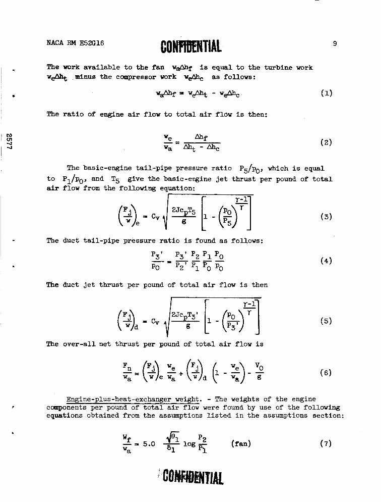
The work avai lable t o the f an w&f i s equal t o the turbine work w& ,minus the compressor work w& as follows:
The r a t i o of engine air flow t o t o t a l air flow is then:
The basic-engine ta i l -p ipe pressure r a t i o P ~ / ~ ~ , which i s equal
t o P ~ / ~ ~ , and T5 give the basic-engine j e t th rus t per pound of t o t a l air flow from the following equation:
The duct t a i l -p ipe pressure r a t i o i s found a s follows:
The duct j e t th rus t per pound of t o t a l air flow is then
The over-al l net t h rus t per pound of t o t a l air flow i s
Engine-plus-heat-exchanger weight. - The weights of the engine components per pound of t o t a l a i r flow were found by use of the following equations obtained from the assumptions l i s t e d i n the assumptions section:
4% p2 2 , 5.0 - 61
log - p'1
(fan) wa
NACA RM E52G16
Wt 6 P4 - = 14.1 - log - W e 64 P5
(compressor) (8)
( turbine) (9)
( shell) ( 10)
The duct heat-exchanger weight per pound of duct air flow wx,&rd is found by the following relation derived from the assumptions as in reference 4:
where wd P wa - we) and (w/A)~,~ is the air flow per unit area in the tubes of the duct heat exchanger and is found from PZ1) TZ1) and The duct heat exchanger 2/d is found by the methods presented in
M21 '
reference 4.
The basic-engine heat-exchanger weight per pound of basic-engine air flow Wx, ./we is found similarly by:
where (w/A)~,~ is the air flow per unit area in the tubes of the basic
engine heat-exchanger as found from P3, T3, and M3. The heat-exchanger
1/13 is found by the metQods of reference 4.
The total engine-plus-heat-exchanger weight per pound of total air flow wT/wa from equations (7) to (12) is then:
NACA iiM E52G16
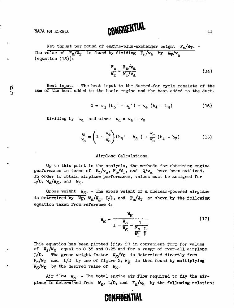
Net t h ru s t per pound of engine-plus-exchanger weight F ~ w ~ . - The value of Ff lT i s found by dividing Fn/wa by WT/wa (equation (13)) :
IU Heat input. - The heat input t o the ducted-fan cycle consis ts of the Ui 4 sum of the heat added t o t he basic engine and the heat added t o the duct. 4
Airplane Calculations
Up t o t h i s point i n the analysis, t he methods f o r obtaining engine performance i n terms of F,Jw~, F,/w~, and &/wa have been outlined. I n order t o obtain a i rplane performance, values must be assigned f o r L/D, ws/Wg, and WK.
Gross weight Wg. - The gross weight of a nuclear-powered a i rplane is determined by WK, wS., L/D, and F ~ / U T as shown by t h e following
-
equation taken from reference 4:
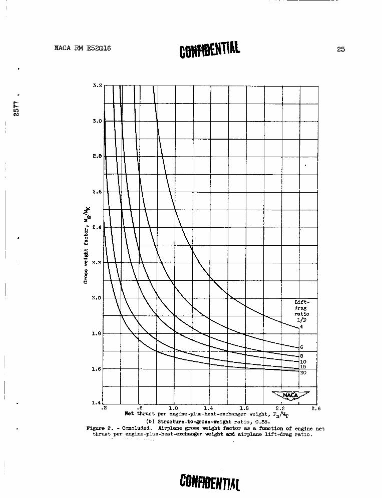
This e uation has been p lo t ted ( f i g . 2) i n convenient form f o r values of W,bg equal t o 0.35 and 0.25 and f o r a range of over-a l l a i rp lane LID. The gross weight f ac to r wg/wK i s determined d i r e c t l y from F& and L/D by use of f igure 2; Wg i s then found by multiplying W&K by the desi red value of WK.
Air flow wa. - The t o t a l engine air flow required t o fly t h e air- plane is determined from Wg, LID, and ~ ~ / v a by the following re la t ion :
NACA RM E52G16
Reactor Calculat ions
Reactor heat r e lease Q. - The reac to r heat r e l e a se Q expressed i n Btu per second i s obtained by mult iplying Q/W, (equation (16 ) ) by
wa ( equation ( 18 ) ) :
The Q ca lcula ted i n t h i s manner includes only the heat required t o power the cycle; no losses or power t o d r ive aux i l i a ry equipment a r e included.
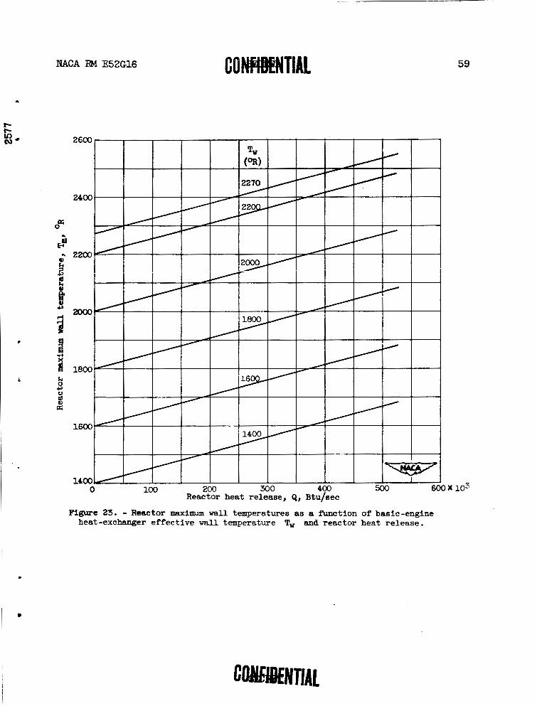
Reactor maximum w a l l temperature Tm. - The temperature Tm i s
obtained by adding t h e difference between t he reac to r w a l l and l iqu id- metal temperature ATy and ATZ ( t h e di f ference between Tw and maximum liquid-metal temperature) t o Tw.
Reactor
Liquid metal --- Actual wall --- Effective wall /
,/ ---- Air
TZ/
Basic-engine heat exchanger
Duct heat exchanger
NACA RM E52G16
A heat balance f o r the two heat exchangers and the reactor w i l l give the desired value of N,; however, t o simplify the calculations, ATZ is assumed t o be 5 0 O F f o r Q=100,000 Btu per second and i s d i r ec t ly propor- t i o n a l t o Q on the bas i s of the performance of the same type of heat exchanger i n the turbojet cycle of reference 4. The 50° F i s conservatvie inasmuch as it is based on t o t a l engine heat requirement ra ther than just on the basic-engine heat requirement, which i s only a par t of the t o t a l heat requirement. This assumption then gives the following r e l a t i on f o r ATz :
The following i s the r e l a t i on used t o compute ATy:
where from reference 10
For lithium, ATy i s given by the following equation (using equation (22)
and da ta from reference ll) :
Then re fe r r ing t o equations ( 2 0 ) ~ (21), and (23)
RESUITS AND DISCUSSION
Engine Performance
Two cases of ducted-fan operation a r e considered i n t he present report . The first case considered assumes t h a t Tw and T4 a r e f ixed at 2270' and 2000~ R, respectively. A value of 2000° R f o r T4 i s current operating pract ice and can be a t ta ined eas i ly with Tw of 2270' R. These temperatures lead t o Tm corresponding t o the bes t which can be
NACA RM E52G16
expected with metal l ic materials . The Twl, T3', M z t were var ied together with p3/p2 and p2/p1 t o determine t h e conditions f o r pe s t Fn/wT. The r e s u l t s of t h i s case a r e presented i n d e t a i l .
I n order t o determine engine performance at reduced Tw, t he second case is considered where Tw = Twl. The values of Tgl, M Z t , p3/p2, and
p2/p1 which give maximum Fn/wT a r e then determined. The r e s u l t s of
these calculations a re compared with the f i r s t s e t .
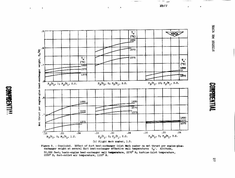
Optimum duct heat-exchanger i n l e t Mach number M Z 1 . - I n f i gu re 3,
Fn/wT i s p lo t ted as a function of j T31 i s held at 1100~ R f o r both
pa r t s of t h i s f igure . Figures 3 ( a ) and 3(b) a re f o r a f l i g h t a l t i t u d e of 50,000 fee t and MO of 0.9 and 1.5, respect ively . The basic engine i s operating with T, = 2270' R, T4 = 2000' R, and M3 - 0.15.
Several combinations of p2/p1, p3/p2, and Twl a r e i l l u s t r a t e d .
For MO = 0.9 ( f i g . 3 ( a ) ) , t he optimum M2' i s about 0.24 or s l i g h t l y under, while f o r a f l i g h t Mach number of 1.5 ( f i g . 3 ( b ) ) , t he optimum occurs around 0.24 or s l i g h t l y higher. The curves ind ica te t h a t t h r u s t per engine-plus-heat-exchanger weight i s not very sens i t ive t o duct- in le t Mach number.
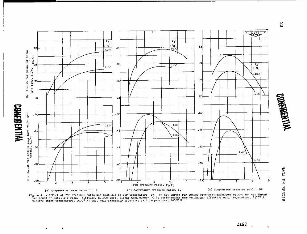
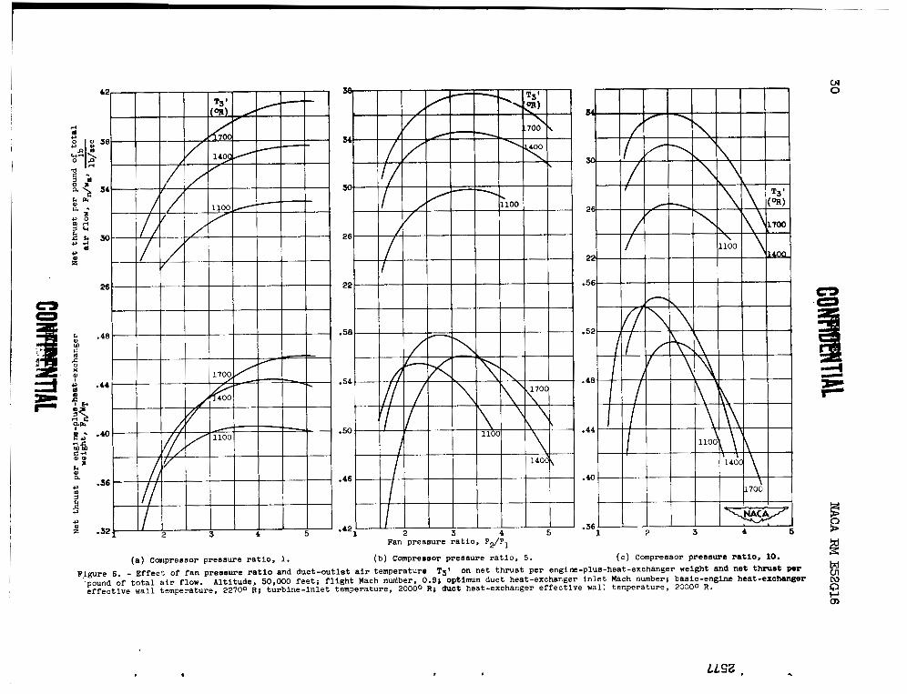
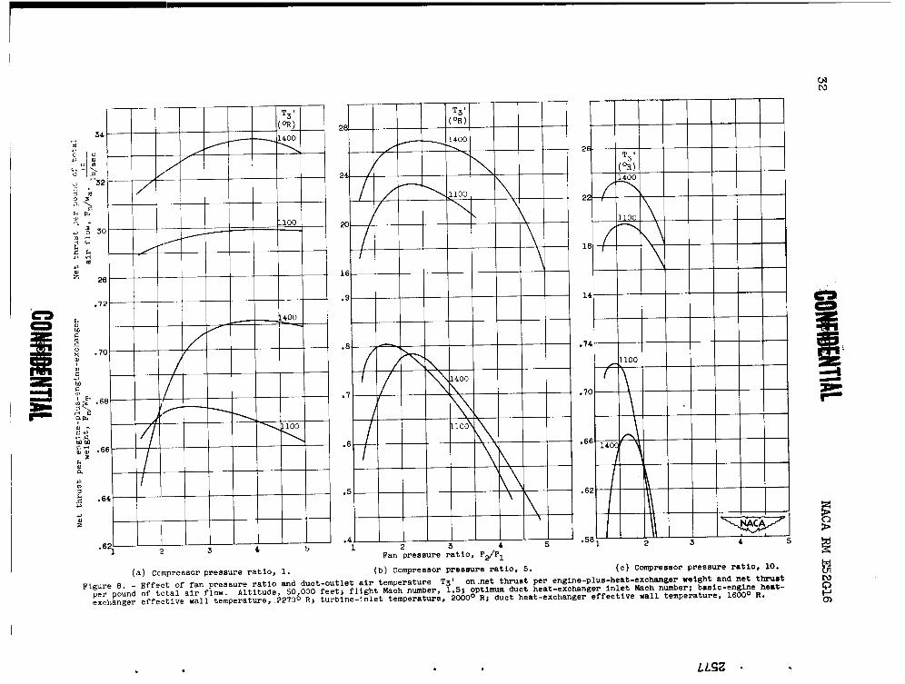
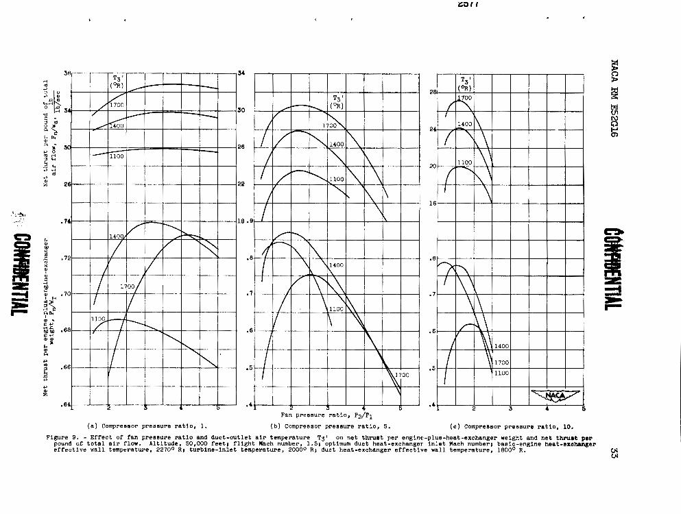
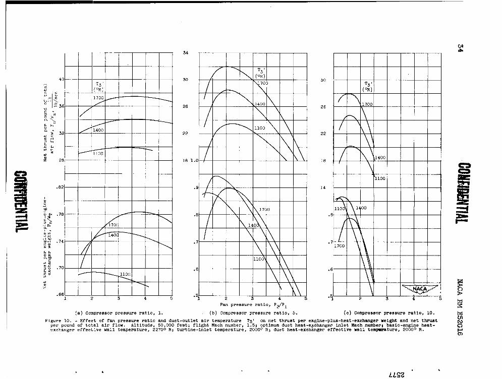
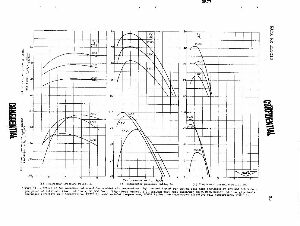
Optimum fan pressure r a t i q p2/pl. - I n f igures 4 t o 11, Fn/wT and
F ~ / w ~ are p lo t ted a s functions of p2/p1 f o r various values of T3', p3/p2 of 1, 5, and 10, and Twl of 1600°, 1800°, 2000°, and 2200' R.
The basic engine i s operating with Tw of 2270° R, Tq of 2000' R, and M3 of 0.15. These f igures show a l l t h e engine performance optimized f o r M Z t .
I n general, increasing the p3/p2 decreases t he optimum p2/p1 f o r
a given value of Twl and Tgl . I n addit ion, it can be seen t h a t the re
i s an optimum p3/p2 for a given value of TW1 and Tg . Furthermore,
the re i s an optimum T3' f o r each Twl. The optimum p2/p1, p3/p2, and
Tgl obtained from these f igures a r e presented l a t e r i n t he repor t .
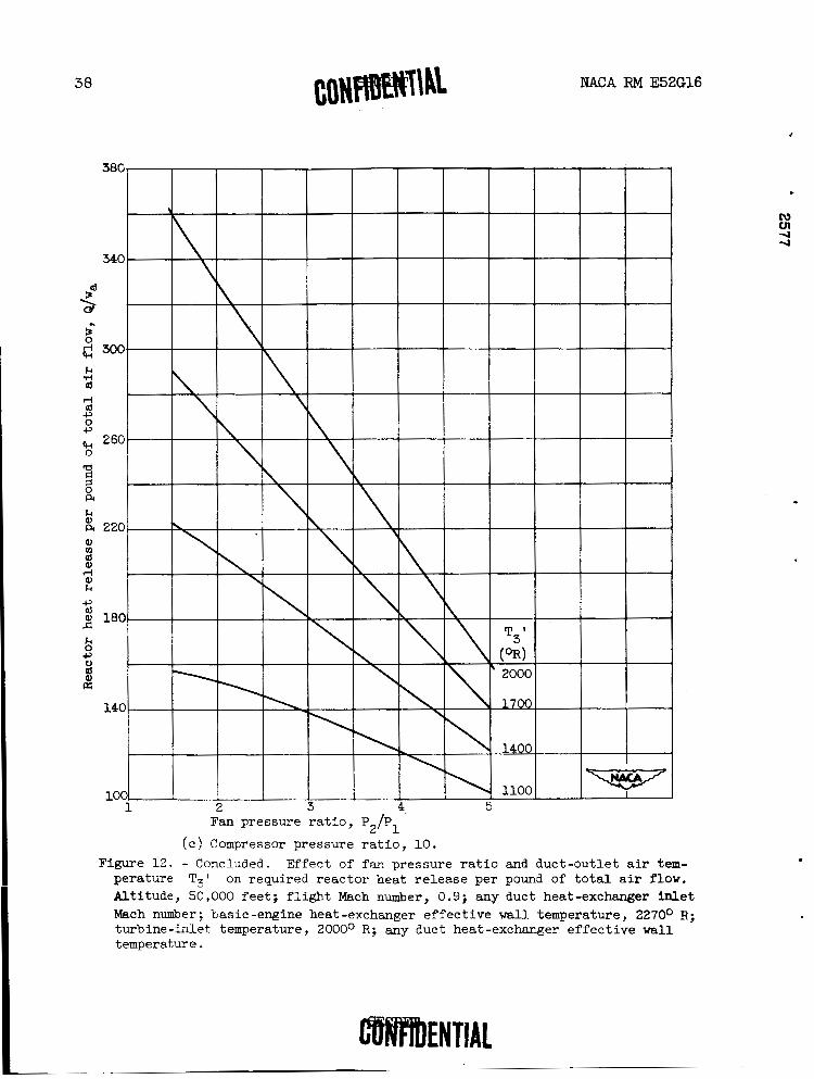
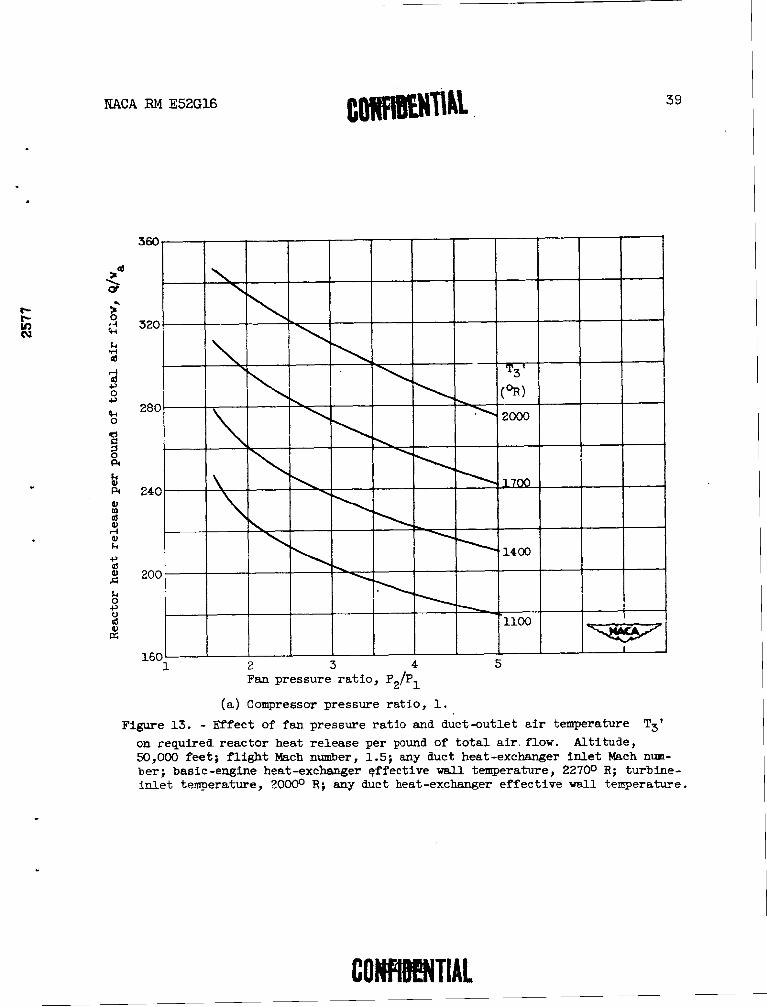
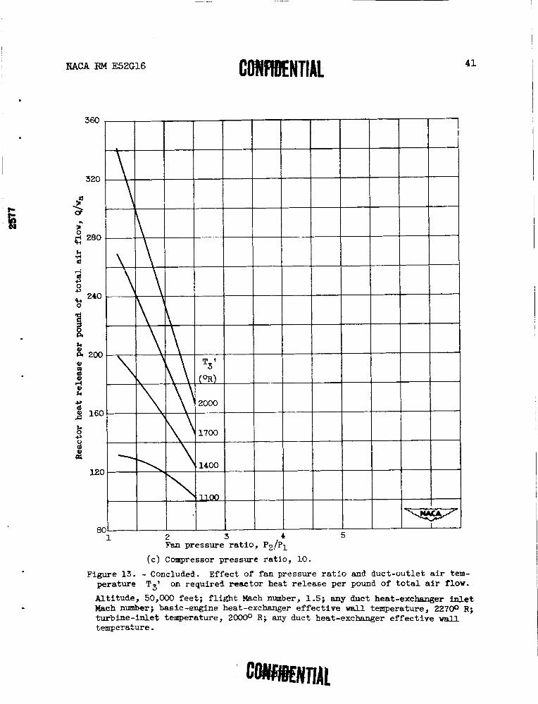
Reactor heat re lease per pound of t o t a l air flow Q/W, and r a t i o of basic-engine air flow t o t o t a l air flow w,/w,. - Values of Q/wa
are shok-ii as a f i ~ n c t i o n of P ~ / P ~ sfid m-1 ' 5 in figures 12 and 13 for
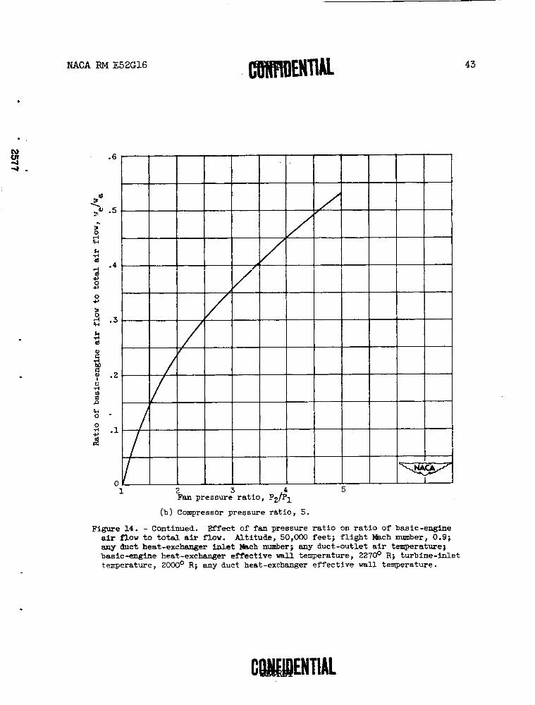
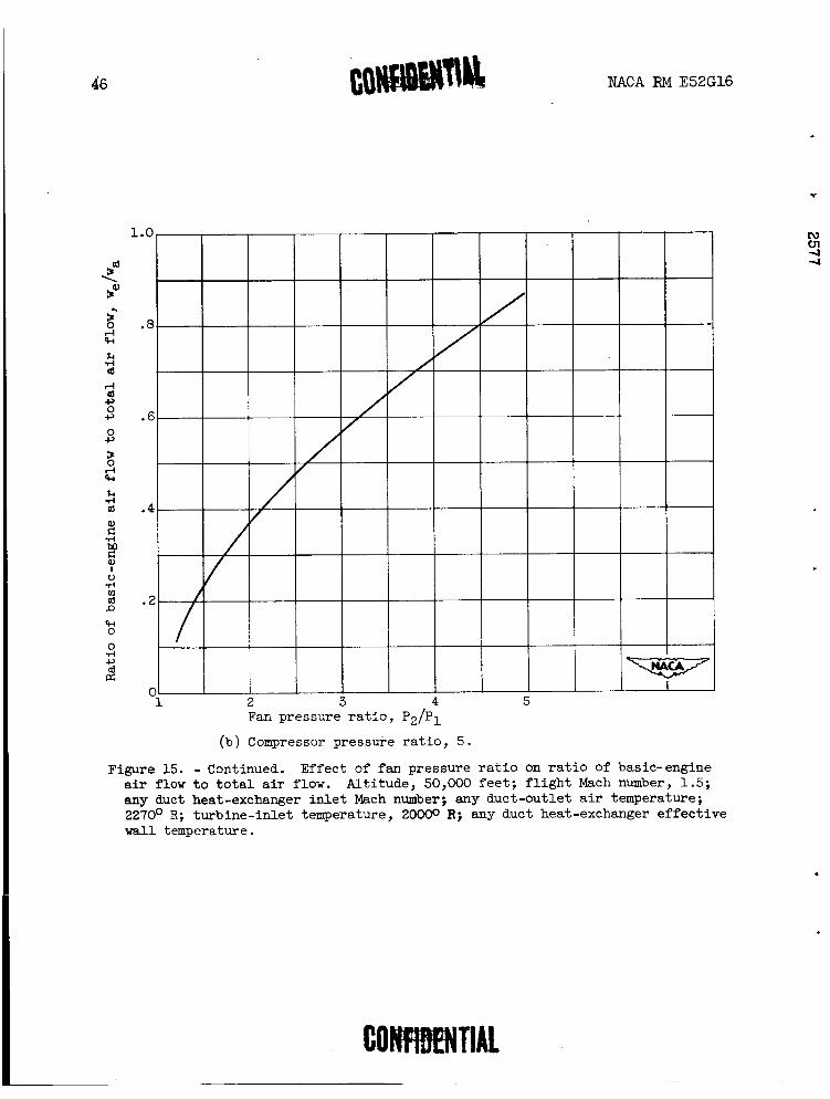
Mg of 0.9 and 1.5, respectively, and a l t i t u d e of 50,000 f e e t . These values correspond t o the engine conditions i n f igures 4 t o 11. Values of w,/w, a r e shown i n f igures 14 and 15 f o r t he same f l i g h t and engine conditions as the previous f igures .
NACA RM E52G16
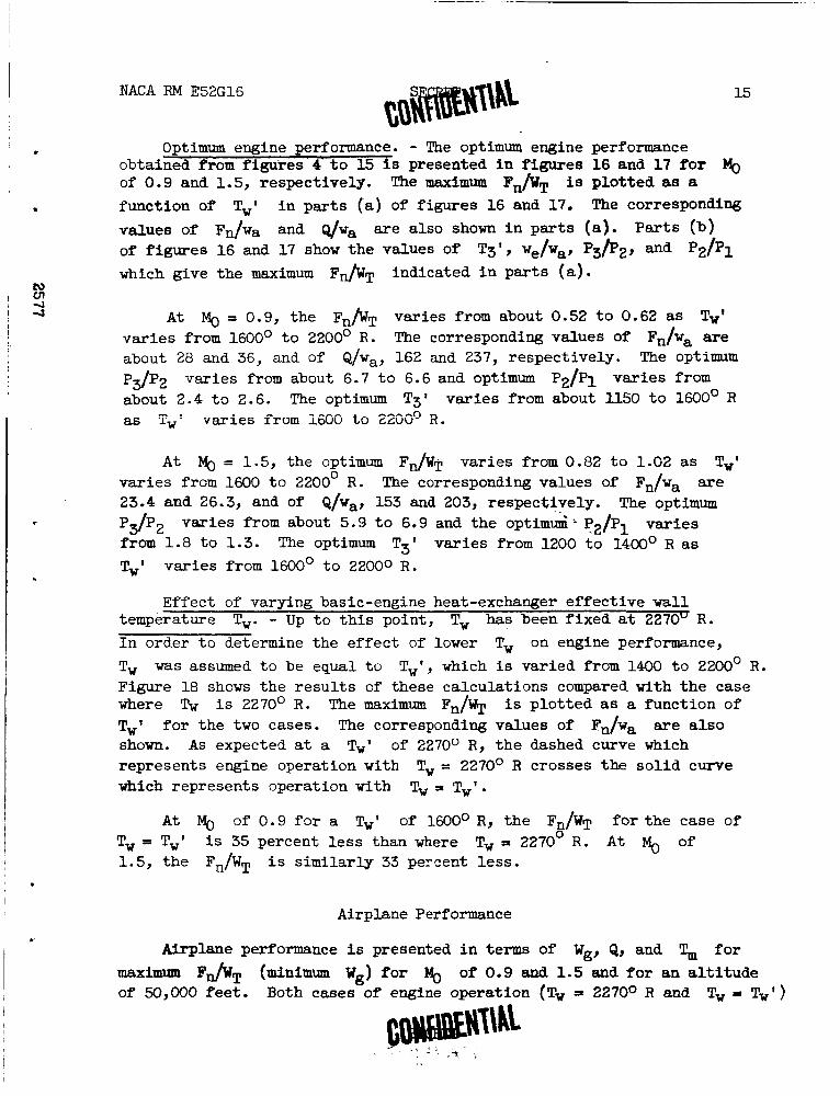
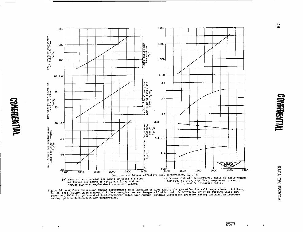
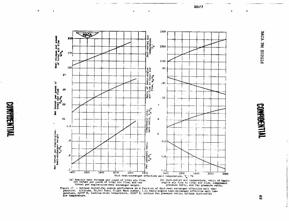
Optimum engine performance. - The optimum engine performance obtained from f igures 4 t o 15 i s presented i n f igures 16 and 17 f o r Mg of 0.9 and 1.5, respectively. The maximum F ~ / W ~ is plot ted as a function of Twl i n par ts ( a ) of figures 16 and 17. The corresponding
values of and &/w, are also shown i n par t s (a). Pa r t s (b) of f igures 16 and 17 show the values of T3', we/wa, p3/P2, and p2/p1
which give the maximum F a T indicated i n par t s (a) .
A t Mg = 0.9, the Fn/WT varies from about 0.52 t o 0.62 as Tw' var ies from 1 6 0 0 ~ t o 2200' R. The corresponding values of Fn/wa are about 28 and 36, and of Q,/wa, 162 and 237, respectively. The optimum
p3/p2 varies from about 6.7 t o 6.6 and optimum p2/p1 varies from about 2.4 t o 2.6. The optimum Tgl var ies from about 1150 t o 1600' R as T varies from 1606 io 2260' R.
A t Mg = 1.5, the optimum F d T varies from 0.82 t o 1.02 a s Twl varies from 16M) t o 2200' R. The corresponding values of FJv, a re 23.4 and 26.3, and of Q/w,, 153 and 203, respectively. The optimum
P ~ / P ~ varies from about 5.9 t o 6.9 and the optim&i ' P ~ / P ~ varies from 1.8 t o 1.3. The optimum Tgl var ies from 1200 t o 1 4 0 0 ~ R a s
Twl var ies from 1600' t o 22000 R.
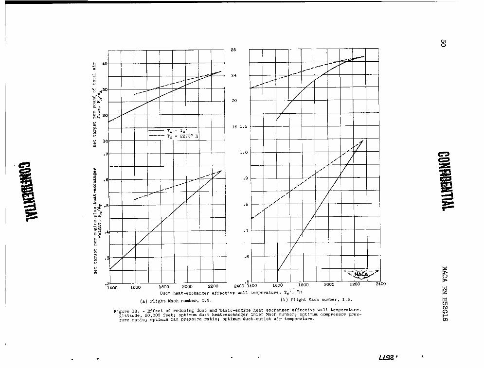
Effect of varying basic-engine heat-exchanger effect ive w a l l temperature Tw. - Up t o t h i s point, Tw has been f ixed at 2270"'R.
I n order t o determine the effect of lower T, on engine performance,
T, was assumed to be equal t o Twl, which is varied from 1400 t o 2200' R. Figure 18 shows the r e su l t s of these calculations compared with the case where Tw i s 2270' R. The maximum Fn/wT i s plot ted a s a function of Twl f o r the two cases. The corresponding values of Fn/wa are a l so shown. A s expected a t a Twl of 2270° R, the dashed curve which represents engine operation with T,= 2270° R crosses the so l id curve which represents operation with Tw = Twl.
A t Mg of 0.9 f o r a Twt of 1600O R, the Fn/wT f o r the case of Tw = TW1 is 35 percent l e s s than where Tw a 2270' R. A t % of 1.5, the F,/w~ i s similarly 33 percent less .
Airplane Performance
Airplane performance i s presented i n terms of Wgy Q y and T, f o r
maximum F ~ V ~ (minimum Ifg) f o r % of 0.9 and 1.5 and f o r an a l t i t ude of 50,000 fee t . Both cases of engine operation ( T ~ = 2270° R and Tw m T w l )
NACA RM E52G16
I
a r e considered. I n the case of Mg of 1.5, two values of L/D ( 6 and 9) I(
a r e shown.
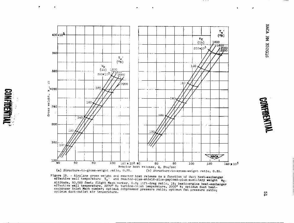
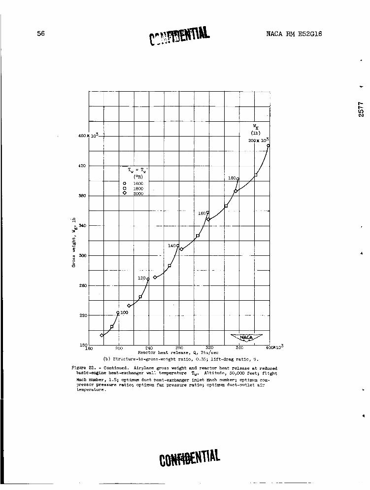
Gross weight Wg, reactor heat re lease Q, and reac tor maximum w a l l rl. - temperature T,. - Figures 19 t o 22 show Wg i n pounds, a s a function of
Q i n Btu per second f o r w,/w= of 0.25 and 0.35, f o r values of WK of 1 - 100,000 t o 200,000 pounds, f o r Twl of 1600°, 1800°, 2000°, and 2200' R, and f o r MO of 0.9 and 1.5. Figure 23 shows Tm as a funct ion of Q f o r a range of Tw from 1400' t o 2270° R.
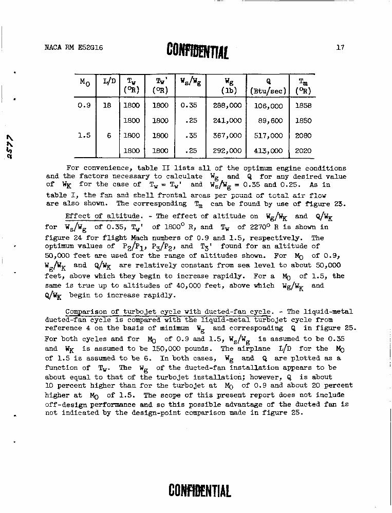
I n the case where Tw = 2270° R ( f i g s . 19 and 20), the gross weight increases a s Twl i s reduced, f o r a given value of WK, but Q decreases. The following t ab l e l is ts t yp i ca l values of Wg, Q, and Tm found from f igures 19, 20, and 23 f o r a value of WK equal t o 150,000 pounds.
For convenience, t ab l e I l ists a l l of the optimum engine conditions and t h e fhctors necessary t o ca lcu la te Wg, w,, and Q fo r any desi red
value of WK f o r .Tw of 2270' R, f o r wS/Wg of 0.35 and 0.25, and for
severa l values of Twl. Also shown i s t he f a n f r o n t a l a rea per pound of t o t a l air flow and t h e s h e l l f r o n t a l a rea per pound of t o t a l air flow. The s h e l l f r o n t a l area i s the sum of t he basic-engine and duct heat- exchanger f r o n t a l areas. The corresponding Tm can be found by use of f igure 23.
Figures 21 and 22 present t he second case where Tw = Tw' for
Mg of 0.9 and 1 .5 and an a l t i t u d e of 50,000 f e e t . The f o l l m i n g t.&le 1j~t.s t . ~ i c = l vn_ppn nQ W- - b - snd Tm f fim ftgEen 21 ..gJ -.I --- ' t o 23 fo r WK equal t o 150,000 pounds:
Tm
2320
2310
2470
2435
Mg
0.9
1.5
L/D
18
6
Tw (03)
2270
2270
2270
2270
Twl (9)
1800
1800
1800
1800
w s h g
0.35
.25
.35
.25
Wg ( l b )
273,000
231,000
325,000
267,000
--
Q ( ~ t u / s e c )
91,000
77,100
383,000
308,000
NACA RM E52G16
For convenience, tab le I1 l i s t s a l l of the optimum engine conditions and the fac tors necessary t o calculate Wg and Q f o r any desired value of WK f o r the case of Tw = TW1 and wS/Wg = 0.35 and 0.25. As i n
t=%Ie I, the f a and s h e l l f r sn ta l =cas pe r poun6 of total f l ~ ~ are a lso shown. The corresponding T, can be found by use of f igure 23.
Mo
0.9
1.5
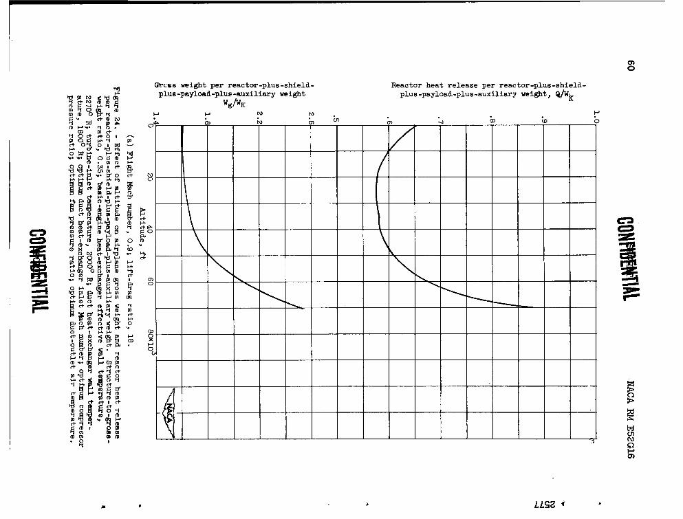
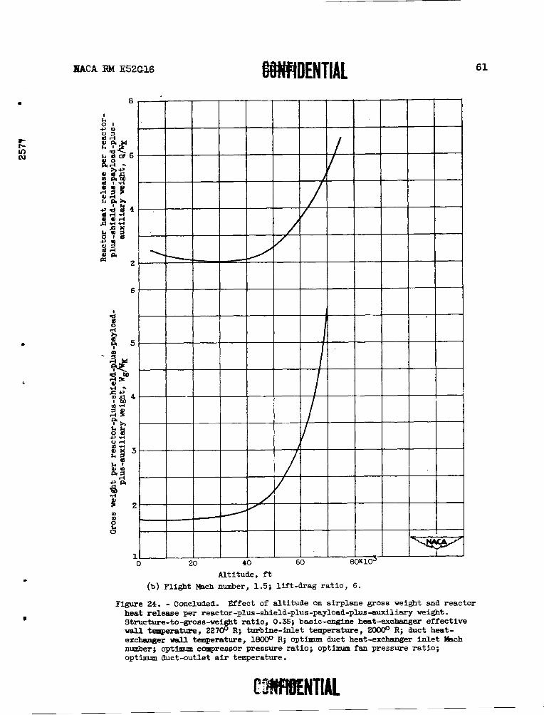
Effect of a l t i tude . - The ef fec t of a l t i t ude on wg/WK and Q / W ~
f o r wS/wg of 0.35, Ty' of 1800' R, and Tw of 2270° R i s shown i n
US&
0.35
.25
.35
.25
figure 24 fo r f l i g h t Mach numbers of 0.9 and 1.5, respectively. The optimum values of p2/p17 P ~ / P ~ , and T3' found f o r an a l t i t ude of 50,000 f e e t are used fo r the range of a l t i tudes shown. For of 0.9, wg/wK and Q/WK a re re la t ive ly constant from sea leve l t o about 50,000
fee t , above which they begin t o increase rapidly. For a Mg of 1.5, the same i s t r u e up t o a l t i tudes of 40,000 fee t , above which wg/wK and Q/WK begin t o increase rapidly.
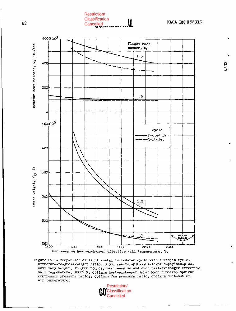
Comparison of turbojet cycle with ducted-fan cycle. - The liquid-metal ducted-fan cycle i s compared with the liquid-metal turbojet cycle from
Wg ( lb )
288,000
241,000
367,000
292,000
Tw' (OR)
1800
1800
1800
1800
LID
18
6
-
reference 4 on the basis of minimum Wg and corresponding Q i n f igure 25.
Tw (OR)
1800
1800
1800
1800
For both cycles and f o r Mg of 0.9 and 1.5, wS/wg i s assumed t o be 0.35 and WK i s assumed t o be 150,000 pounds. The airplane L/D f o r the Mg
Q ( ~ t u / s e c )
106,000
89,600
517,00
413,000
of 1.5 i s assumed t o be 6. I n both cases, Wg and Q a r e p lo t ted as a function of T,. The Wg of the ducted-fan ins t a l l a t ion appears t o be about equal t o tha t of the turbojet instal la t ion; however, Q i s about 10 percent higher than f o r the turbojet a t Mg of 0.9 and about 20 percent
Tm (OR)
1858
1850
2080
2020
higher a t Mo of 1.5. The scope of th i s present report does not include off-design performance and so t h i s possible advantage of the ducted fan is not indicated by the design-point comparison made i n f igure 25.
SUMMARY OF RESULTS
NACA RPll E52G16
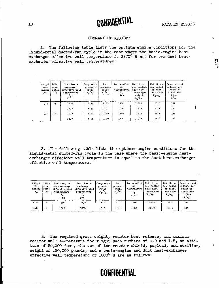
1. The following table lists the optimum engine conditions for the liquid-metal ducted-fan cycle in the case where the basic-engine heat- exchanger effective wall temperature is 2270' R and for two duct heat- exchanger effective wall temperatures.
Flight Mach number
Mo
0.9
1.5
1 -
- Lift drag ratio L/D
Duct heat- exchanger
effective wall temperature
Compressor pressure ratio
p3/pz
2. The following table lists the optimum engine conditions for the liquid-metal ducted-fan cycle in the case where the basic-engine heat- exchanger effective wall temperature is equal to the duct heat-exchanger effective wall temperature.
Fan pressure ratio
~ 2 1 ~ 1
--- Reactor heat release per pound of total air
f low Q/Y,
181
4
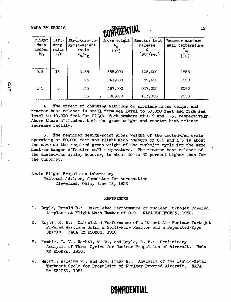
3. Tne required gross weight, reactor heat release, acd-mximmi reactor wall temperature for flight Mach numbers of 0.9 and 1.5, an alti- tude of 50,000 feet, the sum of the reactor shield, payload, and auxiliary +
weight of 150,000 pounds, and a basic-engine and duct heat-exchanger effective wall temperature of 1800' R are as follows:
Duct-outlet air
temperature
Net thrust per engine- plus-heat- exchanger weight
'n/'~
Net thrust per pound of total air flow lJn/wa
Reactor heat release per pound of total air flow Q/Y,
NACA RM E52G16
Gross weight I Reactor heat I Reactor maximum Flight Mach
n-er Mg
-
4. The ef fec t of changing a l t i tude on airplane gross weight and reactor heat re lease i s s m a l l from sea l eve l t o 50,000 f e e t and from sea L e ~ e l to 49,090 feet f o r fiigiit Kach n w e r s of 0.9 and 1.5, respectively. Above these al t i tudes, both .the gross weight and reactor heat re lease increase rapidly.
Lift- drag ra t io
L/D (lb)
5. The required design-point gross weight of the ducted-fan cycle operating at 50,000 f e e t and f l i g h t Mach numbers of 0.9 and 1.5 is about the same as the required gross weight of the turbojet cycle f o r the same heat -exchanger effect ive w a l l temperature. The reactor heat re lease of the ducted-fan cycle, however, is about 10 t o 20 percent higher than f o r the turbojet .
- Structure-to- gross-weight
ra t io ws /Ug
Lewis Fl ight Propulsion Laboratory National Advisory Committee fo r Aeronautics
Cleveland, Ohio, June 12, 1952
release Q
( ~ t u / s e c )
1. Doyle, Ronald B.: Calculated Performance of Nuclear Turbojet Powered Airplane at Flight Mach Number of 0.9. NACA RM E50B23, 1950.
w a l l temperature Tm (5)
2. Doyle, R. B.: Calculated Performance of a Direct-Air Nuclear Turbojet- Powered Airplane Using a Split-Flow Reactor and a Separated-Type Shield. NACA RM E50K06, 1950.
3. Humble, L. V., Wachtl, W. W., and Doyle, R. B.: Preliminary Analysis of Three Cycles fo r Nuclear Propulsion of Aircraft . mACA RM E50H24, 1950.
4. Wachtl, W i N i a m W., and Rom, Frank E.: Analysis of the Liquid-Metal Turbojet Cycle f o r Propulsion of Nuclear Powered Aircraft. NACA RM E51.30, 1951.
NACA RM E52G16
5. Wachtl, William W., and Rom, Frank E.: Analysis of a Liquid-Metal Turbine-Propeller Cycle for Propulsion of Low-Speed Nuclear- Powered Aircraft. NACA RM E52D02, 1951.
6. Behun, M., Rom, F. E., and Hensley, R. V.: Evaluation of a Ducted- Fan Power Plant Designed for High Output and Good Cruise Fuel Economy. NACA RM E50E01, 1950.
7. Trout, Arthur M., and Hall, Eldon W.: Method for Determining Optimum Division of Power Between Jet and Propeller for Maximum Thrust andPower of a Turbine-Propeller Engine. NACA TN 2178, 1950.
8. Pinkel, Benjamin, Noyes, Robert N., and Valerino, Michael F.: Method for Determining Pressure Drop of Air Flowing Through Constant-Area Passages for Arbitrary Heat-Input Distributions. NACA TN 2186, 1950.
9. English, Robert E., and Wachtl, William W.: Charts of Thermodynamic Properties of Air and Combustion Products from 300° to 35000 R. NACA TN 2071, April 1950.
10. Lyon, Richard N.: Forced Convection Heat Transfer Theory and Experi- ments with Liquid Metals. Rep. No. ORNL 361, Tech. Div., Eng. Res. Sec., Oak Ridge Nat. Lab., Aug. 19, 1949. (contract W-7405, eng. 26.).
11. Anon.: Liquid-Metals Handbook. Atomic Energy Commission and Bur. Ships. Navy Dept., June 1, 1950.
TABLE I - OPTIMW ENGINE CONDITIONS FOR BASIC-ENGINE HEAT-EXCHANGER EFFECTIVE WALL TEMPEiATUHE OF 2210° R
TABLE I1 - OPTIMUM ENGINE CONDITIONS FOR BASIC-ENOINE HEAT-EXCHANGER EFPECTIVE WALL TENPWATLTRE EQUAL TO DUCT HEAT-EXCIWIOER EFFECTIVE WALL TEMPERATURE
Gross weight per reactor- plus-payload- plus- auxiliary weight
Reactor heat release per pound of total air flow
'a"",
125.7 180.5 246
125.7 180.5 246
132.1 166.0 212.3
132.1 166.0 212.3
132.1 166.0 212,3 132.1 166.0 212.3
Net thrust per pound of total air flow
Fn/wa
17.53 27.00 36.6
17.53 27.00 36.6
16.52 19-71 25.76
16.52 19.73 25.76
16.52 19.73 25.76 16.52 19.73 25.76
Total air flow per reactor-plus- shield-plus- payload-plus- auxiliary
Net thrust per engine- plus-heat- exchanger
Reactor heat release per reactor-plus- shield-plus- payload-plus- auxiliary
Pan pres- sure ratio
Compressor pressure ratio
2.310 1.916 1.781
1.877 1.608 1.511
2.901 2.440 2.222
2.249 1.961 1.818
2.240 2.041 1.935 1.830 1.695 1.622
weight
WWK
0.9200 .7116 ,665
0.7478 .5973 .5643
3.867 2.421 3.051
2.997 2.749 2.497
1.989 ! 1.907
1.772 1.626 1.584 1.485
Duct-outlet air temp- ature
(OR)
Duct heat- exchanger effective wall
~cture ~ross- ,ght lo
0.007322 .003942 .002703
0,005949 .003309 .002294
0.02927 .02061 .01437
0.02289 .01656 .01178
0.01506 .01149 .00835 0.01231 .009544 .006997
Fan frontal area per pound of total air flow
'3"2
3.0 4.6 6.58
3.0 4.6 6.58
4.0 5.0 4.0
4.0 5.0 4.0
4.0 5.0 4.0
4.0 4.0 4.0
Basic engine heat- exchanger
1.6 2.0 2.57
1.6 2.0 2.57
1.2 1.2 1.4
1.2 1.2 1.4
1.2 1.2 1.4
1.2 1.2 1.4
Shell frontal area per pound of total air flow
Af/wa
0.201
0.201
0.105
0.105
0.105
0.105
temperature (OR)
Tw'
1400 1800 2270
1400 1800 2270
1600 1800 2000
1600 1800 2000
1600 1800 2000
1600 1800 2000
1.35
1.25
>.35
1.25
2.35
>.25
Ad/wa
0.225
0.225
0.153
0.153
0.153
0.153
effective wall tem- erature (OR)
Tw
1400 1800 2270
1400 1800 2270
1600 1800 2000
1600 1800 2000
1600 1800 2000
1600 1800 2000
1000 1260 1630
1000 1260 1630
1120 1260 1400
1120 1260 1400
1120 1260 1400
1120 1260 1400
0.2559 .4332 .629
0.2559 .4332 .629
0.5459 .6942 .8334
0.5459 .6942 .a334
0.5459 .6942 .a334 0.5459 ,6942 .a334
CD- 2407
Figure 1. - Schematic diagram of the nuclear-powered liquid-metal du1:ted-fan cycle.
NACA RM E52G16
Net thrust per engine -plus -heat -exchanger Weight, F , / W ~ (a) Structure-to-groes-weight ratio, 0.25.
Figure 2 . - Airpiae Goes e i g h t factor as a function of engine net thrust per engine-plus-heat- exchanger weight and airplane l i f t ldrsg ratio.
(a) Flight k c h number, 0.9.
w e 5. - Effect of duct heat-exchanger inlet Efach number on net thruet per engine-plus-cxchanger *i6ht at several duct heat-exchanger effective wall temperature8 T,'. Altihb, 50,000 iceti baaic-engine heat-exchanger w a l l tcqxrature, 22700 R; turbine-inlet temperature, 20000 R) duct-outlet air t a - perature, llOOo R.
(b) Flight Mach number, 1.5.
Figure 3. - Concluded. Effect of duct heat-exchanger inlet k c h number on net thrust per engine-plur- exchanger weight at several duct heat-exchanger effective wall temperatm.es Twt. Altitude,
50,000 feet; basic -engine heat -exchanger wall taqprrature, 2270' R; turbine-inlet temperature, 2000~ R; duct-outlet air temperature, llwO R.
Figure 4. - Effect of fan pressure ratio and duct-outlet air temperature on net thrust per engine-plus-heat-exchanger welght and net thrust per pountl of total air flow. Altitude, 50,000 feet; flight Mach number,T$:9; baslc-engine heat-exchanger effective wall temperature, 2210° R; turbine-inlet temperature, 20000 R; duct heat-exchanger effective wall temperature, 16000 R.
LLSZ
Fan pressure ratio, r2/p1
(a) Compressor preeeure ratio, 1. (b) Compressor pressure ratio, 5. (c) Compressor pressure ratio, 10. Figure 5. - Effect of fan pressure ratio and duct-outlet air tempergture T3' on net thrust per engine-plus-heat-exch'angsr weight and net thmst p&
pound of total air flow. Altitude, 50,000 feetj flight Mach 'number, 0.91 optimum duct heat exchanger inlet Mach number; basic-engine heat-exchanger effective wall temperature. 2270° R # turbine-inlet temperature, 2000° R J duct heat-exchanger effective wall temperature, 180O0 R.
(a) Ccmlpressor pressure ratio, 1. ,,re 6. - Effec; of fan pressure rat10 and duct-outlet alr tempentun Tss on net thrust per engln-plus-heat-exchmger welgnt and net thruet ~r * pound of total air flow. Altitude, 50,000 feet; fllght Mach nuniber, 0.9) o p t l m duct heat-exchanger Inlet Mach number; basic-engla h e a t - e u h ~ g e r effective wall l;emperature, 22700 R; turbine-inlet temperature, 20000 R; duct heat-exchanger effective wall temperature, 20000 R. 0
Figure 7. - Effect of fan prerrurm ratio ana duct-outlet air trmprrature T3' on net thntrt per rwinr-plur-heat-rxoknger weight and net t b r t per pound of total air flow. Altitude, 60,000 feet) flight Maoh numbrr 0.91 optlanun duot hut-exohanger inlet Maoh number) bario-m&n wt-k.lyrr effeotive wall temperature, 22700 Rj turbine-inlet *c%p?~tr-lure, 20600 R) duot heat-exohanger effrotive wall temperatme, 22000 R.
(E1 I-'
(c) Compressor pressure ratio, 10.
Figure 9. - Effect of fan pressure ratio and duct-outlet air temperature TJ' on net thruat per engine-plus-heat-exchanger weight and net thruat per pound oE total air flow. Altitude, 50,000 feeti flight Mach number, 1.5; optimum duct heat-exchanger inlet Mach number8 basic-engine heat-exchnger effective wall temperature, 2270° Rj turbine-inlet temperature, 2000° R I duct heat-exchanger effective wall temperature, 1800° R. W
Figure 10. - Effect of fan pressure ratio and duct-outlet air temperature Tj' on net thrust per engine-plus-heat-exchanger weight and net thrust per pound of total air flow. Altitude, 50,000 feat; flight Mach number, 1.51 optimum duct heat-eychanger inlet Hach number; basic-engine heat- exchanger effective wall temperature, 22700 R; turbine-inlet temperature, 2000° Rj duct heat-exchanger effective wall tempcu!ature, 2000° R.
Flgure 11. - Effect of fan pressure ratio and duct-outlet air temperature Tgt on net thrust per engine-plus-heat-exchanger weight and net thrust per pound of total air flow. Altitude, 50,000 feet; flight Mach number, 1.5; optimum duct heat-exchanger Inlet Mach numbers basic-engine heat- exchanger effective wall temperature, 2270° R i turbine-inlet temperature, 20000 Rj duct heat-exchanger effective wall temperature, 2200° R . .
NACA RM E52G16
Fan pressure r a t i o , p2/p1
(a) Compressor pressure ra t io , 1.
Figure 12 . - Effect of fan pressure r a t i o and duct-outlet a i r temperature T3' on required reactor heat release per pound of t o t a l a i r flow. Altitude, 50,000 f e e t ) fligbt Mach number, 0.9) any duct heat-exchanger i n l e t Mach num- ber; basic -engine heat -exchanger effect ive wall temperature, 2270° R; turbine- i n l e t temperature, 2000° R; any duct heat-exchanger effective w a l l temperature.
Fan pressure ratio, p2/P1
(b) Compressor pressure ratio, 5.
Figure 12. - Continued. Effect of fan pressure ratio and duct-outlet air tem- perature T3' on required reactor heat release per pound of total air flw. Altitude, 50,000 feet; flight Mach number, 0.9; any duct heat-exchanger inlet Mach number; basic-engine heat-exchanger effective w a l l temperature, 2270° R; turbine-inlet temperature, 2000° R; any duct heat -exchanger effective w a l l temperature.
NACA RM E52G16
Fan pressure ratio, p2/p1
(c) Compressor pressure ratio, 10.
Figure 12. - Concluded. Effect of f m pressure ratio and duct-outlet air tem- perature T3' on required reactor heat release per pound of total air f l o w . Altitude, 50,000 feet; flight Mach number, 0.9; any duct heat-exchanger inlet Mach number; basic-engine heat-exchanger effective wall temperature, 2270° R; turbine-iclet temperature, 2000° R; any duct heat-exchanger effective wall temperature.
Fan pressure ratio, P2/P1
(a) Compressor pressure ratio, 1.
Figure 13. - Effect of fan pressure ratio and duct-outlet air temperature T3' on required reactor heat release per pound of total air.flow. Altitude, 50,000 feet; flight Mach number, 1.5; any duct heat-exchanger inlet Mach num- ber; basic-engine heat -exchanger effective wall temperature, 22700 R; turbine- inlet temperature, 2000° R; any duct heat-exchanger effective wall temperature.
NACA RM E52G16
Fan pressure ratio, p2/p1
(b) Compressor pressure ratio, 5.
Figure 13. - Continued. Effect of fan pressure ratio and duct-outlet air tem- ----L..-- p ~ ; ~ ~ ~ ~ ~ ~ T3' ~ i i yeq-&:red reactcr hzat release per pound nf t.ot~1.1 air flow. Altitude, 50,000 feet; flight Mach number, 1.5; any duct heat-exchanger inlet Mach number; basic-engine heat-exchanger effective wall temperature, 2270° R; turbine-inlet temperature, 2000° R; any duct heat-exchanger effective wall temperature.
(c) Compressor pressure ratio, 10.
Figure 13. - Concluded. Effect of fan pressure ratio and duct-outlet air tem- perature T3' on required reactor heat release per pound of total air flov.
Altitude, 50,000 feet; flight Mach number, 1.5; any duct heat-exchanger inlet Mach number ; basic -engine heat-exchanger effective w a l l temperature, 22700 R; turbine-inlet temperature, 2000° R; any duct heat-exchanger effective wan temperature.
NACA RM ~ 5 2 ~ 1 6
(a) Compressor pressure ratio, 1.
Figure 14. - Effect of fan pressure ratio on ratio of basic-engine air flow to total air flow. Altitude, 50,000 feet; flight Mach number, 0.9; my duct heat -exchanger inlet Mach number ; nny duct -outlet air temperature; basic - engine heat -exchanger effective wall temperature, 22700 R; turbine-Inlet temperature, 2000' R; any duct heat-exchanger effective wall temperature.
1 2 3 4 5 Fan pressure ratio, p2/P1
(b) Compressor pressure ratio, 5.
Figure 14. - Continued. Effect of fan pressure ratio on ratio of basic-engine air flow to total air flow. Altitude, 50,000 feet; flight frlach number, 0.9; any duct heat-exchanger inlet Mach number; any duct-outlet air temperature; basic -engine heat -exchanger effective m a l l terqperature , 2270° R; turbine-inlet temperature, 2000~ R; any duct heat-exchanger effective wall temperature.
NACA RM E52G16
Fan pressure ratio, p2/p1
(c) Compressor pressure ratio, 10.
~ i ~ u r e 14. - Concluded. Effect of fan pressure ratio on ratio of basic-eogine air flow to total air flow. Altitude, 50,000 feet; flight Mach number, 0.9; any duct heat-exchanger inlet Mach number; any duct-outlet air temperature; basic-engine heat-exchanger effective wall temperature, 2270° R; turbine-inlet temperature, 20000 R; any duct heat-exchanger effective w a l l temperature.
NACA RM E52G16
Figure 15. - Effect of fan pressure ratio on ratio of basic engine air flow to total air flow. Altitude, 50,000 feet; flight Mach number, 1.5; any duct heat-exchanger inlet Mach number; any duct-outlet air temperature; basic- engine heat exchanger effective wall temperature, 22700 R; turbine-inlet temperature, 2000° R; any duct heat-exchanger effective wall temperature.
Fan pressure ratio, pZ/pl
(b) Compressor pressure ratio, 5.
Figure 15. - Continued. Effect of fan pressure ratio on ratio of basic-engine air flow to total air flow. Altitude, 50,000 feet; flight Mach number, 1.5; any duct heat-exchanger inlet Mach number; any duct-outlet air temperature; 2270' R; turbine-inlet temperature, 20000 R; any duct heat-exchanger effective wall temperature.
NACA RM E52G16
(c) Compressor pressure ratio, 10.
Figure 15. - Concluded. Effect of fan pressure ratio on ratio of basioengine air flow to total air flow. Altitude, 50,000 feet; flight Mach number, 1.5; any duct heat-exchanger inlet Mach number; any duct-outlet air temperature; 2270' R; turbine-inlet temperature, 2000° R; any duct heat -exchanger effective wall temperature.
00
Duct heat-exchanger effective wall temperature, TWt, OR (a) Reactor heat release per pound of total air flow, (b) Duct-outlet air temperature, ratio of basic-engine
net thrmat per pound of total air flow; and net air flow to total air flow, compressor pressure thrust per engine-plus-heat exchanger weight. ratio, and fan pressure ratio.
FLgure 16. - Optimum ducted-fan engine performance as a function of duct heat-exchanger effective wall temperature. Altitude, 50,000 feet; flight Mach number, 0.9; basic-engine heat-exchanger effeotive wall temperature, 2270° R; turbine-inlet tem- perature, 2000' R; optimum duct heat-exchanger inlet Mach number; optimum compressor pressure ratio; optimum fan pressure ratio; optimum duct-outlet air temperature.
(a) Reactor heat release er pound of total air flow, (b) Duct-outlet atr temperature ratio of basic- net thrust per pound OF total air flow; and net engine air Plow to total air fiow, compressor thruat per engine-plue-heat exchanger weight. presaure ratio, and fan pressure ratio.
Figure 17. - Optimum ducted-fan engine perfomnoe as a function of duct-heat exchanger effective wall tem- perature. Altitude, 50,000 feet; flight Mach number, 1.51 baaic-engine heat-eachanger effective wall tem- perature, 22700 R; turbine-inlet temperature, 2000' R; optimum fan pressure ratio; optimum duct-outlet air temperature.
Duct heat-exchanger effective wall temperature, Tw', OR
Figwe 20. - Airplane gross weight and reactor. heat release as a functior of duct heat-exchanger wall temperature Tw1 and reactor-plus-shield- plus-payload-plus-auxiliary weight WK. Altitude, 50,000 feet; flight Mach number, 1.5; basic-engine heat-exchanger effective wall tem- perature, 2270' R; turbine-inlet temperature, 2000° R; optimum duct heat-exchanger inlet Mach number; optimum compressor pressure ratio; optimum fan pressure ratio; optimum duct-outlet air temperature.
NACA RM E5ZG16
. -. (a) Structure-to-gross-weight ratio, 0.25.
Figure Z l . - Airplane gross weight and reactor heat release at reduced basic-engine heat-exchanger effective wall temperature TY. Altitude, 50,000 feet; flight Mach number, 0.9; airplane lift-dreg ratio, 18; optimum duct heat-exchanger inlet Mach number; optimum compressor pressure ratio; optimum fan pressure ratio; optimum duct-outlet air temperature.
NACA RM E52G16
Reactor heat release, Q, ~ t u / s e c
(b) Structure-to-gross weight ra t io , 0.35.
Figure 21. - Concluded. Airplane gross weight and reactor heat release a t reduced basic-engine heat-exchanger effective w a l l temperature T,. Altitude, 50,000 fee t ) f l i gh t Mach num- ber, 0.9; airplane l i f t -d rag ra t io , 18; optimum duct.heat-exchanger inleZ Mach number; optimum compressor pressure ra t io ; optimum fan pressure r a t io ; optimum duct-outlet a i r ternperature.
Figure 22. - Airplane gross weight and reactor heat release at reduced basic- en- heat-exchanger effective ua I l teaperatwe T,. Ntitude, 50,000 feet; fliat lbch number, 1.5; optimum duct heat-exchanger inlet Uach number; o p t h compressor presaure ratio; optbum fan pressure ratio; optimum duct- outlet air temperature.