NASA Technical Memorandum 100661 Results of EVA/Mobile Transporter Space Station Truss Assembly Tests J. J. Watson, W. L. Heard, Jr., H. G. Bush, M. S. Lake, J. K. Jensen, R. E. Wallsom, and J. E. Phelps November 1988 i_sls I_ASA) al S cscL 22B G3118 National Aeronautics and Space Administration Langley Research Center Hampton, Virginia 23665 N89-13qS3 gaclas 0183250
Transcript
NASA Technical Memorandum 100661
Results of EVA/Mobile Transporter
Space Station Truss Assembly Tests
J. J. Watson, W. L. Heard, Jr., H. G. Bush, M. S. Lake,J. K. Jensen, R. E. Wallsom, and J. E. Phelps
November 1988
i_sls I_ASA) al S cscL 22B
G3118
National Aeronautics andSpace Administration
Langley Research CenterHampton, Virginia 23665
N89-13qS3
gaclas
0183250
RESIJI.,T$ OF EVA/MOBILE TRANSPORTERSPA_'E STATION TRUSS ASSEMBLY TESTS
by
J. J. Watson, W. L. Heard Jr., H. G. Bush, M. S. LakeJ. K. Jensen, R. E. Wallsom, J. E. Phelps
INTRODUCTION
The Space Station Freedom (SSF) baseline configuration is shown in Figure 1. The primary structureis an erectable truss beam, 110 meters long, with a five-meter-square cross section. The currentbaseline proposal for on-orbit construction makes use of a Mobile Transporter (MT) attached to the topof an Assembly Work Platform (AWP) and two astronauts in extravehicular activity (EVA) asdiscussed in reference 1. The construction method uses the EVA astronauts to assemble the station
from Astronaut Positioning Devices (APD's) on the AWP. The AWP, which is a partially deployable,
partially erectable truss structure approaching 10 meters in length, remains attached directly to theOrbiter sills for all construction activities associated with the first two SSF buildup flights. The
construction tasks include integrated installation of SSF system components as well as assembly of the
primary truss structure. Currently, half of the truss beam with associated essential subsystems is to becompleted during Flight 1 and the other half during Flight 2. However, this scenario is undergoingclose scrutiny due to the complexity of the tasks involved and manifesting considerations.
The NASA Langley Research Center (LaRC) has an ongoing in-house research program to study amobile transporter concept that could be used not only, as generally accepted, for maintenance, repair,and growth activities after SSF is operational, but also for construction during the first two SSF buildup flights. This alternate construction scenario eliminates the AWP and the structural complexity andrisk of moving the SSF truss system after each bay is completed. Instead, the SSF truss would beattached to the Orbiter sills through a transition truss, and the MT equipped with APD's (as originallyconceived in references 2 and 3), would "walk" along the completed truss segment carrying the
astronauts and building material as additional structure is being assembled. Although use of the MT inthis manner requires the EVA crew and MT to move away from the cargo bay during the first two
Station buildup flights, this is a requirement that is accepted for later flights.
This paper presents the results of a ground test program designed to study EVA assembly of near fullscale SSF u'uss structure with integration of utility trays using the NASA LaRC alternate constructionscenario. Test hardware, assembly procedures, and assembly times are presented for 1-g and neutral
buoyancy tests.
MOBILE TRANSPORTER ASSEMBLY SCENARIO FOR SPACE STATION
A schematic of the Mobile Transporter (MT) as envisioned for the assembly of Space Station is shownin Figure 2. The MT would be folded in the Shuttle cargo bay and remotely deployed to an uprightposition when orbit is achieved. The Space Station truss consists of a series of segments called bays.Each bay is a five meter cube, and all bays are identical. Guide pins, attached to the truss nodal joints,form the interface between the MT guide mils and the truss structure. The truss is assembled one bayat a time above the MT platform by two EVA astronauts. The astronauts are secured in foot restraintsattached to APD's. The APD's are not complex robotic arms, but relatively simple devices used to
move the astronauts to various positions on their respective sides of the MT so that the requiredconstruction tasks can be accomplished. After the crew has assembled a bay, the MT drawbar extends(as shown in Fig. 2) pushing the MT one bay-length away from the completed structure along the trusslongitudinal axis. The next contiguous bay is then assembled, after which the drawbar is retracted tograsp new nodal joint guide pins and extended to move the transporter into position for assembly of
the next bay. In this way the MT steps along the truss as the truss is being assembled. The platforn_ isused to transport Space Station operational equipment which requires integrated installation during theprimary truss assembly. A Shuttle type remote manipulator am1 attached to the MT is cnvisioncd tosupport these tasks.
SCENARIO FOR INTEGRATED INSTALLATION OF UTILITY TRAYS
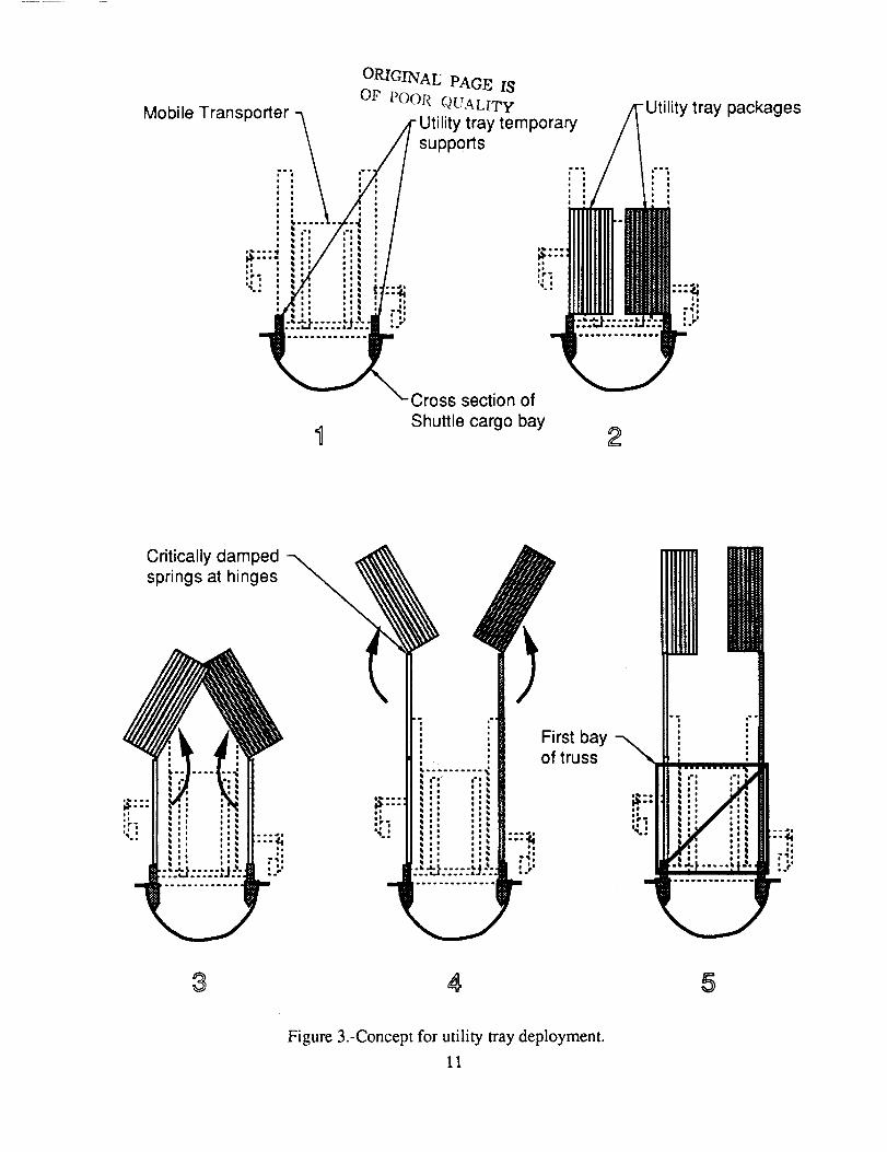
A major concern associated with SSF construction is installation of the utility system that is vital to theSSF operation. It is generally accepted that the electrical and fluid utility lines will be housed inprotective trays that are attached to the inside of the primary truss structure. Although electrical andfluid line connections are beyond the scope of this investigation, a scenario for integrated installation ofthe utility trays during truss assembly was addressed. This scenario permits folded bay-lengthpackages of tray segments to automatically deploy to their proper positions prior to assembly of thesupporting bay of the truss. The deployed tray segments can then be attached directly to the trussnodes during truss assembly. This procedure, by minimizing astronaut handling, is designed to have aminimal impact on truss assembly.
A series of sketches representing the general procedure is shown in Figure 3. Sketch 1 represents across section of the Shuttle cargo bay with the MT deployed and ready for assembly to begin.Temporary utility tray supports are shown deployed on either side of the cargo bay. The utility traysare fan-folded into 5 m long packages. Critically damped springs are used at the hinge lines. TheShuttle Remote Manipulator System is used to unstow the packages and attach them to the supportsbefore truss assembly is begun (sketch 2). The EVA astronauts release latches that allow the packagesto unfold two bay lengths (sketches 3 and 4). The EVA crew then assembles the first bay of truss andattaches the utility trays (sketch 5). The MT then translates one bay-length, after which the EVA crewunlatches the utility tray package (allowing it to unfold another bay length) and assembles the nexttruss bay. The procedure is repeated until the desired truss configuration is achieved.
TEST HARDWARE
Mock-up and Operation of Mobile Transporter
Figure 4 is a schematic of the MT mock-up used in the Space Station truss EVA constructionsimulations conducted in 1-g at LaRC and in neutral buoyancy at the Marshall Space Flight Center'sNeutral Buoyancy Simulator (NBS). The MT mock-up was supported on a tower and remainedstationary during the tests. The truss structure was assembled one bay at a time under the transporter.When a bay was completed, it was moved out of the work area by the drawbar thus producing therelative motion between the truss and MT to simulate the MT "walking" along the completed trussstructure. A remote manipulator arm was not required nor used for these tests. As indicated in the
inset, the preferred position for the EVA astronauts is with their heads pointing away from the MT.This orientation provides the best visibility and least obstructed work area. However, for comfort andsafety reasons, the test subjects were positioned with their heads pointing toward the MT during the 1-g and neutral buoyancy tests. To accomplish this, the lower segment of each astronaut positioningdevice (APD) was slaved to the motion of the rotating upper segment to remain vertical at all times.For the flight article the lower segment is envisioned to be independently rotated about and elbow joint.The APD's could also be moved one bay-length forward or aft as indicated by the arrows in thesketch. The two rectangular canisters shown attached to the top of the MT are for stowage of trussstruts and nodes.
Strut and Node Stowage
All struts and nodes were stowed in two stowage canisters. The stowage arrangement is shown inFigure 5. Although the size of the NBS test facility limited the size of truss that could be assembled toonly three bays, the canisters were sized to hold enough struts and nodes for assembly of I0 bays oftruss (approximately half the size of the Space Station Revised Baseline Configuration) plus several
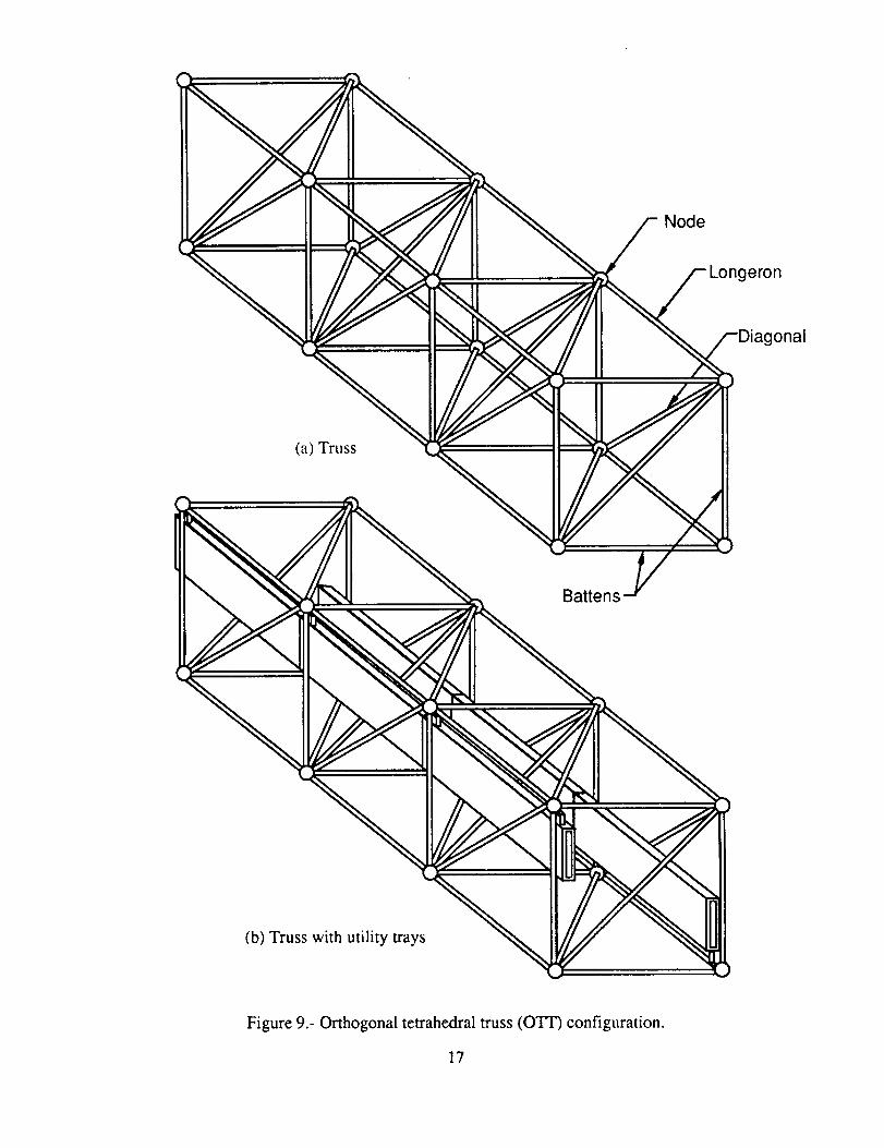
Thetrusshardwarewascomposedof struts(termedlongerons,battens,anddiagonalsasindicatedinFig.9) andnodes.Thestrutsweretwo-inch-diameteraluminumtubeswith a fitting ateachendtopermitsideinsertioninto thematingnodefitting duringtrussassembly.Thesefittings alsowereused
3
to setall thestrutlengthsto within tolerancevaluesprior to thetests.Forthe l-g tests,thestrutswerefabricatedfrom thinwall 7075aluminumtubingto minimizetheirweight(approximately8.8lb. foreachlongeronandbattenstrut,and11.9lb. for adiagonalstrut). Thestrutsfor theneutralbuoyancytestsconsistedof weldedsectionsof 6061aluminumtubingwith a 1/8inchwall thickness.Theweldedsectionsconsistedof internalairtightchambersfor positivebuoyancyandfloodedchamberstowhich leadshotcouldbeaddedor removedfor neutralbuoyancyadjustment. Carewastakento setall strutlengthsaccurately,however,manyof thestrutsfabricatedfor neutralbuoyancyusedid notmeetthestraightnessrequirementsdueto incorrectweldingtechniquesandinadequatefixturing. Inorderto meetNBSscheduling,theas-fabricatedstrutswereusedin thetests,althoughthecontractorfabricatedsomereplacementsthatwereusedin latertests.
A typical trussnodaljoint is shownin Figure10. Thenodes(topphotograph)weremodifiedspheresto whichupto 26fittingscouldbeattachedfor accommodatingstrut(andpayload)connections.(Withthisarrangementvarioustrussconfigurationsarepossibleandthepotentialfor trussgrowthisprovided).Thejoint usedwasdesignedatNASA LaRCto facilitateEVA assemblywhile retainingstructuralefficiency. An earlyversionof thejoint ispresentedin reference5. A patternwaspaintedon thestrutandnodefittingsto provideahighlyvisiblelockpositionindicator.ThephotographlabeledINSERTshowsthepatternwhenthestrutlockingcollar ispositionedfor insertioninto thematingnodefitting. The photographlabeledCAPTUREDshowsthepatternwhenthestrutiscapturedin thenodefitting. With thelockingcollar in thispositionthestrut-to-nodejoint is securebutwill notprovidethedesignstructuralstiffness.By manuallyrotatingthelockingcollar45degrees,thelockingpatternbecomesawidebar(photographlabeledLOCKED),andthejoint is lockedinto itsdesignpreloadedcondition.Thenodescouldnotbemadeneutrallybuoyantwithoutaddingexternalflotation. Thus,following assemblyof agivenbay,andbeforethetrusswasmovedby thedrawbar,flotationwasattachedby scubadiverstoeachof thelowernodesoneachsideof thetrussto neutrallybuoyit andthenodedirectlyaboveit. In thiswaythetrussneutralbuoyancywasmaintained.
Utility Trays
Theintegratedutility trayinstallationsweredoneonly in neutralbuoyancytests.As shown in Figure11, two neutrally buoyed tray systems were provided, one for each side of the three-bay truss. An
individual tray was nominally a 3 X 15 X 0.5-foot aluminum box with a dry weight of approximately150 lb. Three trays were linked together with simple hinges to form the utility tray system for one side
of the truss. Four tubular members were attached to an edge of the unfolded tray system at intervalscorresponding to truss node locations. These tubular members, which had end fittings identical to thestrut end fittings, were used to attach the trays to the truss nodes during assembly.
Figure 12 is a schematic showing the method used to install the trays during assembly of the truss.The view is looking downward on the mobile transporter (represented by the dashed lines). Since theMT support tower (also represented by dashed lines) would interfere with the initial, inward,unfolding of the utility tray packages, the packages were predeployed one bay-length. The twopartially unfolded tray packages were then supported in place on the support tower. (This methodsimulated the temporary support system shown in Figure 13, envisioned for the Shuttle cargo bay, thatholds the packages in place during assembly of the transition truss and first bay of SSF truss). Theneutral buoyancy tests began with assembly of the initial truss bay and attachment of the first tray totwo of the nodes. The pins used to secure the second and third trays in the folded configuration werethen pulled and the trays unfolded with the aid of scuba divers (simulating springs) as the drawbar wasextended to move the completed bay out of the work area.
TEST PROGRAM
Assembly tests were conducted both in 1-g and in neutral buoyancy. The 1-g tests were performedwith the test subjects in street clothes. The neutral buoyancy tests were performed with the testsubjects in scuba, and also with the test subjects in pressure suits (Extravehicular Mobility Units(EMU's)). These tests were conducted in an attempt to isolate the effects of water drag and pressure
suitencumbranceonassemblytimes.Dueto theeffectsof gravitytheassemblyproceduresdevelopedfor the 1-gtestswerenecessarilysomewhatdifferentfrom thoseusedfor the0-g tests.However,the1-gassemblyprocedure,thoughnotasefficientastheneutralbuoyancyprocedure,wasduplicatedinsomeof the .scuba neutral buoyancy tests for comparison of assembly times. The size of the NBS testfacility (75 feet in diameter and 40 feet deep) limited the size of truss that could be continuouslyassembled to only three bays. Complete or partial disassembly was accomplished by scuba diversbetween assemblies during a given test.
The assembly procedures used for the pressure suited neutral buoyancy tests were also duplicated inscuba tests. The difference in assembly times were assumed to be attributable to pressure suitencumbrance. The following three scenarios were used for the pressure suited assembly tests: (1)consecutive three-bay truss assemblies without integrated installation of utility trays (with associatedscuba disassemblies of approximately 17 minute average durations), (2) consecutive three-bay trussassemblies with integrated installation of utility trays (with associated scuba disassemblies ofapproximately 26 minute average durations), and (3) an initial three-bay truss assembly with integratedutility trays followed by consecutive two-bay assemblies (with associated scuba disassemblies of twobays of approximately 10 minute average durations). During the scuba disassemblies, the test subjectswere idle. The duration of a test was limited to approximately two hours by NBS safety rules whichpermitted only one decompression stop for the test subjects when being brought to the surface. Thetest scenarios were developed in order to build as much truss structure as possible in the limited timeavailable for a given test. Tethering of the hardware was not addressed in these tests.
l-g Tests
Figure 14 shows a 1-g test in progress. Figure 14(a) shows the first bay being assembled. The trusssupport frame, shown at the lower right; was used in the 1-g tests to carry the weight of the truss afterassembly. Figure 14(b) shows the entire three-bay truss. To facilitate handling by the test subjects,itwas necessary to develop unique assembly procedures for the 1-g tests because of gravity effects. Theshort bracket shown attached to the tower in Figure 14(a) was used as a prop to help support the uppertruss struts as they were being passed from the test subject on the far side of the truss to the test subjecton the near side. When a lower truss member was being passed across the truss, an engineer on thefloor assisted by manually supporting the free end of the strut.
Numerous truss assemblies were performed in 1-g by a number of different subjects including twoNASA astronauts in order to check out the hardware, develop efficient procedures,and train testsubjects and console operators. Following these preliminary tests, four timed tests were performed inwhich well trained engineers were used as test subjects and expert console operators, exclusively. Athree-bay truss was assembled for each of these tests.
Neutral Buoyancy Tests
Figure 15 is a schematic showing the assembly sequence used for the neutral buoyancy tests. After thefirst batten frame is assembled, all remaining bays are assembled identically following a very simpleand easily memorized routine. Test subject 1 always moves in a counterclockwise direction, while thetest subject 2 always moves in a clockwise direction. Struts and nodes are removed from the stowagecanister and temporarily stowed on the APD foot restraint handrails when the test subjects pass thecanisters so that no long distance translations are required for material resupply.
Figure 16, 17, and 18 show neutral buoyancy tests in progress. Figure 16 shows a scuba assembly,and Figures. 17 and 18 show pressure suit assemblies both with and without integrated installation of
utility trays. As with the 1-g tests, numerous assemblies for hardware checkout, proceduraldevelopment, and personnel familiarity were performed in scuba. Several additional pressure suit testswere also performed to verify the test setup. Two different pairs of test subjects were used in these
tests as well as two pairs of console operators. Eight timed assembly tests were performed duringwhich a total of 49 bays of truss were assembled by a single pair each of trained, engineer test subjects
andexpertconsoleoperators, respectively. In the last five of these tests 34 bays of truss were
assembled with integrated installation of utility trays. Two additional tests were performed by a pair ofNASA astronauts to provide them with some hands-on experience with the assembly procedures andhardware, and to solicit their comments for consideration.
TEST RESUI_TS
Pressure Suited Neutral Buoyancy Tests
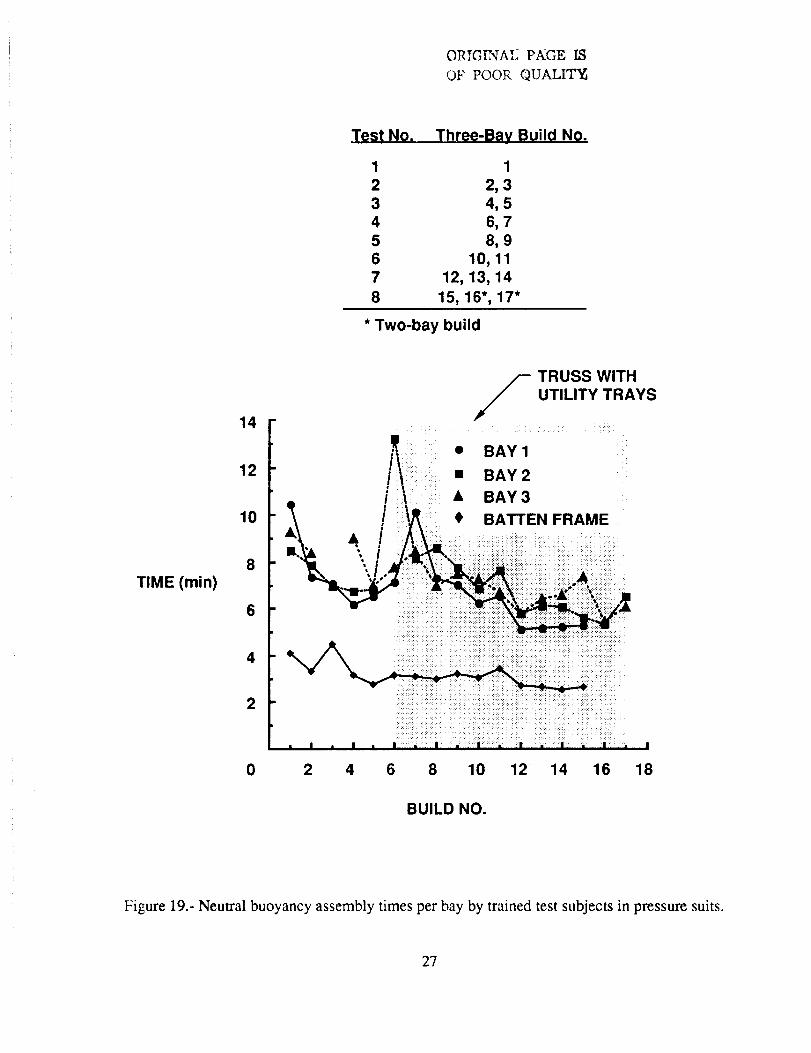
The assembly times using trained engineers as test subjects for the first batten frame and succeedinggeneral bays of the truss are presented in Figure 19 as a function of build number. The build number
applies to a three-bay assembly, with the exception of builds 16 and 17 which were two-bayassemblies performed during Test 8. As can be seen, the assembly times generally decreased as thetest subjects and the console operators became more experienced. The few spikes in the data reflectminor difficulties encountered while making some of the strut-to-node connections (attributed to strut
crookedness). However, all connections were accomplished by the test subjects without scuba diverassistance. It is interesting to note that as the test subjects became more experienced, and developedtheir techniques, the assembly times which included integrated installation of utility trays became fasterthan the assembly times without utility trays. These assembly times are considerably faster than the13.5-14 minutes per bay (with no utility trays) reported in reference 6 for neutral buoyancy assemblytests of competing Space Station truss concepts. The tests reported in reference 6, however, usedseveral different AWP hardware configurations, as well as different assembly procedures than thoseused in the tests reported herein. The fidelity of the test fixtures used in the ref. 6 tests and the
assembly procedures were compromised significantly by the small size of the Weightless EnvironmentTraining Facility (WETF) in which they were performed, and by the use of many pairs of astronauttest subjects performing only one or two tests each, so that they could not become thoroughly trainedor highly experienced with the various AWP hardware designs and assembly concepts. Such "quick-look" tests should not be considered verifications of a concept.
The assembly times by a pair of astronaut test subjects for the first batten frame and succeeding generalbays of the truss in the present tests are presented in Figure 20 as a function of build number. One ofthese astronauts had no previous experience with the Mobile Transporter or the truss hardware, andrelatively few hours of neutral buoyancy experience in the pressure suit. The other astronaut hadperformed several 1-g assemblies with the MT using the same truss hardware, but different assemblyprocedures. However, this astronaut had many hours of neutral buoyancy pressure suit experienceplus approximately 12 hours of actual on-orbit EVA structural assembly experience with the ACCESSShuttle flight experiment (ref. 5). A comparison of Figs. 19 and 20 shows that the astronaut assemblytimes were somewhat greater than those from the first few tests of the experienced test subjects, andsignificantly greater than the times realized in the latter builds. Except for the two spikes that areindicative of additional time taken to install crooked struts, the astronaut times also show a generallydownward trend as experience is gained. These results demonstrate the importance of using only welltrained test subjects to verify assembly times and evaluate hardware or concepts.
Comparison of l-g, Scuba, and Pressure Suit Three-bay Assemblies
In order to provide data that may be useful for more accurate estimations of on-orbit assemblytimes from data obtained in 1-g and neutral buoyancy assembly tests, an attempt was made toisolate the effects of water drag and pressure suit encumbrance. Figure 21 shows a comparison ofthree-bay truss assemblies performed in 1-g with the test subjects in street clothes, and in neutralbuoyancy with the test subjects in either scuba or pressure suits. All of these results were obtainedwith the same pair of trained, engineer test subjects and the same pair of trained console operators.
The neutral buoyancy tests included integrated installation of utility trays, whereas utility trayinstallation was not possible with the 1-g test setup. The average assembly time for the three-baytruss without utility trays was approximately 14.82 minutes in 1-g and 15.73 minutes in scuba.Because these assembly times are so close and the effects of gravity were significant deviations
6
from thescubatests,it is unlikelythatanyrealisticconclusionsontheeffectsof waterdragcanbedrawn.
However,theresultsfromthescubaandpressuresuitneutralbuoyancytestscanbeusedto estimatetheeffectsof pressuresuitencumbrancebecausethesetestswereessentiallyidenticalexceptfor thetestsubjects'attire. Theaverageassemblytimefor athree-baytrusswasapproximatelyfour minuteslongerin pressuresuitsthanin scuba.Theseresultssuggestthat,with theparticularassemblyconceptstudied,afive to six secondsperstrutpenaltyin assemblytimeisdirectly attributableto thecurrentpressuresuit (ExtravehicularMobility Unit (EMU)) design,andprimarily theglovedesign. It wasnecessaryto usetheseries1000glovesin thesetestsbecausetheseries3000gloveswerenotavailable.Howevertheastronautscommentedthatuseof series3000gloveswith low torquewristbearingswouldimproveperformanceconsiderably.
ConcludingRemarks
Eighttimedneutralbuoyancytestswereconductedtoevaluatetheuseof a MobileTransporterconceptin conjunctionwith EVA astronautsto constructSpaceStationtrussstructure.A three-bayorthogonaltetrahedraltrussconfiguration(consistingof 44 two-inch-diameteraluminumstruts)with a 15-footsquarecrosssectionwasrepeatedlyassembledby asinglepair of trainedpressuresuitedtestsubjectsworkingfrom theMobileTransporterastronautpositioningdevices(mobilefoot restraints).Thetestsubjectsweretranslatedto variousworksitesattheapproximaterateof onefoot persecond.A totalof48baysof trusswereassembled,34of which includedintegratedinstallationof utility trays.Theunitassemblytimeaveragedfrom thelastfour assembliesof thethree-baytruss(44struts)was27.6s/strut,or 6rain/bay,which includesintegratedinstallationof utility trays.Tetheringof thehardwarewasnot addressedin thesetests.
Therelativelyhighlydevelopedjoint, designedat theNASA LangleyResearchCenter,wasusedforall structuralconnections.In severalinstancesdifficulties in makingjoint connectionswereencounteredwhichwerelikely causedby useof crookedstrutsthatwereexcessivelyoutof tolerance.However,trainedtestsubjectswereabletom',_eall of thestructuralconnectionswithoutassistancefrom utility divers.Therapidassemblytimesachieveddemonstratethecompatibilityof thejointdesignwith EVA assembly.Thepatternpaintedoneachjoint washighlyvisiblefrom longdistancesandeasilyinterpretedbythetestsubjectsandconsoleoperatorsasto thelockedor unlockedconditionof thejoint andthedirectionof rotationof thelockingcollarnecessaryto achieveeitherof theseconditions.
Theresultsof thesetestsindicatethatEVA assemblyof SpaceStationsizestructurecanbesignificantlyenhancedwhenusinga MobileTransporterequippedwith astronautpositioningdevices.Rapidassemblytimescanbeexpectedandaredependentprimarilyon the rate of translationpermissible for on-orbit operations. The concept used to demonstrate integrated installation of utility
Adkisson,R. W.:"The Role of a Mobile Transporter in Large Space Structures Assembly andMaintenance." Engineering, Construction, and Operations in Space, August 1988, pp. 787-796.
Mikulas, Martin M., Jr.; Bush, Harold G.; Wallsom, Richard E.; Dorsey, John T.; and Rhodes,Marvin D." A Manned-Machine Space Station Construction Concept. NASA TM 85762,February 1984.
°
4,
Bush, Harold G.; Mikulas, Martin M., Jr.; Wallsom, Richard E.; and Jensen, J. Kermit:
Conceptual Design of a Mobile Remote Manipulator System. NASA TM 86262, July 1984.
Sutter, Thomas R. and Bush, Harold G.: A Comparison of Two Trusses for the SpaceStation Structure. NASA TM 4093, 1989.
. Heard, Walter L., Jr.; Bush, Harold G.,; Watson, Judith J.; Spring, Sherwood C.; and Ross,Jerry L.: Astronaut/EVA Construction of Space Station. AIAA Paper No. 88-2454.Presented at the AIAA SDM Issues of International Space Station Conference, Williamsburg,Va., April 21-22 1988.
. Lichwala, B. E.: Selection of an Assembly Truss Member Arrangement for the NASA SpaceStation. Presented at the AIAA SDM Issues of International Space Station Conference,Williamsburg, Va., April 21-22 1988.
ORIGINAL PAGE IS
OF POOR QUALITY
tin,
O
O
¢-O
!
, ,...,
9
Astronauts in EVA work from foot restraints attached to
positioning devices to assembly truss and install payloads
,e canisters for
Guide rails truss struts and nodes
Platform for transporting payloads
_ /Remote manipulator armfor manipulation of large
payloads
Drawbar
Guide
pins
Figure 2.-EVA/Mobile Transporter concept for assembly of Space Station.
Figure 11. - Utility tray packages used in neutral buoyancy assembly tests.
19
"_'_'i_'" __ Mobile Tran sport e r
1. Utility trays unfolded one
bay-length prior to start
of assembly test
II "'''-kl"-----.e .!_'_:.7.:: .........................._ ...........................rnE• .......... • r ................ ... .......... w i...... I--:._ - ........ "JI,I . ...... "t I l i
" '""'Ii 4, . i i a o Iee • BG O0 : O I
i • i_ l I i II _ ..... i I I I It I I I ........ _ I
..... ::::::' .: " I
4. Drawbar extended; scuba divers
complete unfolding and Iockup
;4":_:%gl I.QeI iel
:: :'I,IlI L .. I 1 re:
II llllllIlll I II iii iI .... I........[ il'-.I --°- °....... A.iI f_ _t e I I i Ii B o t0t I iI o°_ • I e e ii i
o o • • loo i eoo o* I°l o _ I• • i e o .°......... ° I e
• ..leieo e i I
L...°...°..I i o_1 "%'1,
......................... _o
............... ; .................... I " "l,-------------,,........... -.a
l0on|| e--.
2. Assemble first bay and
attach trays
e e I..o
la
ill...illll ..... °.ilLllllllq I
,............,i I • o•I i i
11.-;." I: ',e ------- u a
........ ° .... °ioiI
5. Assemble second bay and attach trays
,
.........................................Trays unfold as drawbar isextended
II Ii|III
II
ea • _lI Ie I •oo_ a al
i • . nl i
: _-'." ..I. ,; ..... .._.lb.... ...... o
I I e :
O|OO
6. Retract drawbar to grasp nodes ofsecond bay
Figure 12- Schematic of utility tray deployment for neutral buoyancy tests.
2O
ORIGIN_,.EP._GEISOF POORQUALITY
TRANSITION
UTILITY TRAY PACKAGE
TEMPORARY SUPPC
Figure 13. - Computer drawing of predeployment of three-bay utility tray system.
21
ORIGINAL PAGE Ig
OF POOR QUALITY
(a) Assembly of first I_ay.
(b) Three-bay truss completed.
Figure 14. - Three-bay Space Station truss assembly in 1-g with Mobile Transporter.