76
Retrofits and Actuator Upgrades Kurt Christianson, PE Application Engineer, Americas FSRUG 1-18-17

Retrofits and Actuator Upgrades
Kurt Christianson, PE
Application Engineer, Americas
FSRUG
1-18-17

Operating Experience, Teflon Balance Seals
Manufacturer’s include Furon and Variseal.
The concern is FME when the seal fails.

Operating Experience, Teflon Balance Seal
‣ The balance seal
eliminates flow
through the balance
holes in the plug (or
disc).
‣ Teflon seals are low
friction.
‣ Reduce actuator
force required
‣ Reduce hysteresis
‣ Teflon seals provide
tight shutoff.

Operating Experience, Teflon Balance Seal
Balanced Plug vs. Unbalanced
Unbalanced Plug Balanced Plug (No Step)
Teflon Balance
Seal

Operating Experience, Teflon Balance Seal
“The picture of the orange finger indicating a wire caught in a disk stack was taken from River Bend. They had similar
FME issues as Grand Gulf. It did not look like a variseal failure, because they use a ribbon element inside the Teflon
balance seal. Today we use St. Gobain "Furon" balance seals, which is a competitor of Variseal. The Furon balance seal
has a ribbon spring element as well.
The Teflon balance seal manufactured by Furon which is similar to the Variseal design is the preferred option for plug
sealing when Teflon is allowed in nuclear applications. The Teflon balance seals used by IMI CCI have no record of
chronic failure. If other manufactures are seeing failures of similar balance seals in their valve designs (i.e. Copes
FWREG at Riverbend) it may be due to valve design.
There is no concern of failure with Teflon balance seals in DRAG® valve designs, and IMI CCI will continue to use these
seals when possible to take advantage of their superior sealing capabilities, long life, and low friction.”
Sincerely,
Kurt Christianson, PE
Application Engineer, Nuclear
IMI CCI


© 2002. CCI – Control Components Inc. All rights
reserved. 1/23/2017 8

© 2002. CCI – Control Components Inc. All rights
reserved. 1/23/2017 9

© 2002. CCI – Control Components Inc. All rights
reserved. 1/23/2017 10
© 2002. CCI – Control Components Inc. All rights
reserved. 1/23/2017 11
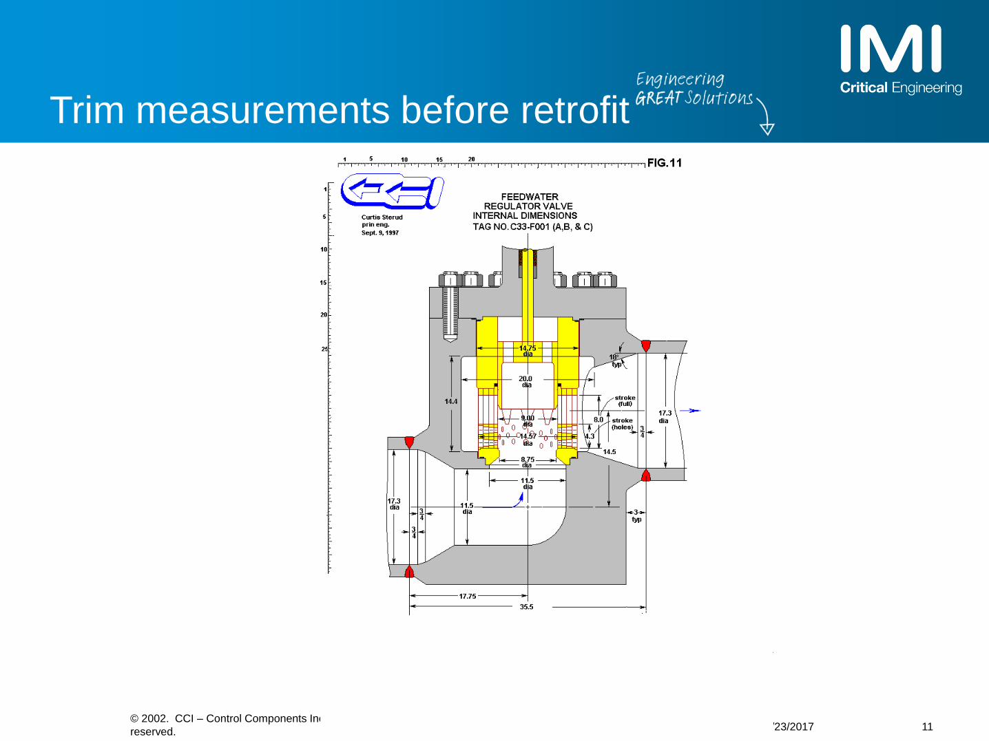
Trim measurements before retrofit

© 2002. CCI – Control Components Inc.
All rights reserved.
1/23/2017 12

© 2002. CCI – Control Components Inc. All rights
reserved. 1/23/2017 13

© 2002. CCI – Control Components Inc. All rights
reserved. 1/23/2017 14

© 2002. CCI – Control Components Inc. All rights
reserved. 1/23/2017 15

© 2002. CCI – Control Components Inc. All rights
reserved. 1/23/2017 16
FWR RETRIFITED WITH CCI DRAG TRIM

© 2002. CCI – Control Components Inc. All rights
reserved. 1/23/2017 17
REPLACEMENT OF THE ACTUATOR

© 2002. CCI – Control Components Inc. All rights
reserved. 1/23/2017 18
RECIRC RETROFITED WITH CCI DRAG TRIM

© 2002. CCI – Control Components Inc. All rights
reserved. 1/23/2017 19

© 2002. CCI – Control Components Inc. All rights
reserved. 1/23/2017 20

© 2002. CCI – Control Components Inc. All rights
reserved. 1/23/2017 21
ATMOSPHERIC VENT VALVE

We are an international leader in the engineering and manufacturing of critical service flow control valves for the Nuclear Industry.
We solve control valve problems.

Our global reach

IMI CCI (California) manufacturing
• 194,000 sq. ft. facility
• 300 employees
• DRAG® technology
• Full manufacturing
• Located in Rancho Santa Margarita, CA
• Primary supply location for North America
• Designed to maintain fast-response
capability for parts and maintenance
services
• Sales/customer service, engineering,
project management & quality
management resources
• Spare parts, repairs, and technical
service
• Full manufacturing/machining/welding/
assembly & test capability
• Assembly & test for complete valves
• Stellite machining
• Valve repair services
• Spare parts supply & distribution
• Technical services
• Project management
• Design engineering for DRAG®
• Upgrade design team
• Quality management services
CapabilitiesCredentials Products
• ASME N & NPT certification
• 10CFR50 Appendix B, Part 21
• HAF604 (China)
• NB National Board certified
• Dir. 97/23/CE (PED)
• API 6A
• RTN & GOST-R (Russia)
• CRN (Canada)
• NUPIC and NIAC audited/approved
• ISO 9001:2000 (2008)
• Residual heat removal applications
• ASDV/CSDV/TB
• Power operated relief valve
• Feedwater/level control
• Reactor water cleanup
• Recirculation valves
• Temperature/pressure control
• Chemical volume & control valves
• AUX steam control
• Pump test loop/sampling
• Heater drain valves
• Pneumatic actuation

Presentation Overview
25
Severe Service Applications
DRAG® Technology Overview
QuickTrak® Valve Positioning System
High Rangeability Valve Design
IMI Technologies for Nuclear

ButterflyBall
Globe
Severe service
Control Valve HierarchyPe
rfo
rman
ce
Severity

DRAG® Valve Applications in Nuclear (not all!)

© 2002. CCI – Control Components Inc. All rights
reserved. 1/23/2017 28
CCI APPLICATIONS IN PWR UNITS


ISA guide: velocity control limits
Service conditions
Gas / steam kinetic
energy criteria
Equivalent liquid /
water velocity
psia ft / s
Continuous service single
phase fluids70 100
Cavitating & multiphase fluid
outlet40 75
Vibration sensitive system 11 40
Intermittent duty 150 -
Trim outlet kinetic energy criteria
KE =V2
2gc

Velocity control principle
‣ Single stage pressure drop
DP = P1 - P2

Velocity control principle
‣ Multiple stages of pressure drop

Single Stage and Multi Stage Valve Trim
33
‣ DRAG® Eliminates Cavitation

Cavitation damage can not be predicted.
Cavitation Damage – Not Enough Stages

Determining valve trim loss coefficients
• The loss coefficients of control valves can be calculated using the
piping system methods from Crane 410.
• Loss coefficients can be summed in series. The summation must
include the effect of changes in area. This can be done using the area
expansion coefficient, Ec.
exitn
ci
ientryT K
E
KKK 2
2
1
A
AEc

Typical loss coefficients for control valves
• Single-stage cage has K = 1.5.
• Three-stage cage with Ec = 2 has K = 1.97
• A series of right angle turns with Ec = 1.072
have an average loss coefficient of K = 1.32
(determined experimentally).
• Four right angle turns with Ec = 1.072 have
K = 6.7.
• Discharge velocity can be found using
Darcy equation, pressure drop, density, and
loss coefficient.
K
PgV
net1442 D
Cv=29.9d^2/K^0.5

Key Critical Service Elements
Process Insight
• Understanding of the applications
Reliability
• Control of Fluid Velocity/ Kinetic
Energy
• Material of Construction
• Robust Design
• Multi Stage Pressure Reduction
• Discrete Flow Passages
Control Resolution
• Actuator/Positioner
• Trim Design
Multi Stage Pressure Reduction
Discrete Flow Passages

DRAG® velocity control flow path
Over the plug flowUnder the plug flow

DRAG® EDM Diskstacks
Inlet
Outlet
Inlet
Inlet Inlet

DRAG® Laser Cut Disk Stacks

Feedwater Regulator Valve
‣ Rangeability for low flow
conditions
‣ Rangeability achieved
through trim
characterization

Basic Design Parameters
42
Low pressure drop
High CvFull Load
High pressure drop
Low Cv
Startup

SPINDLE
BONNET
PLUG
BONNET FLANGE
DISK STACK &
TRIM ASSEMBLY
Disk Stack in Control Valve

Quick Change Trim
‣ No parts screwed or welded into the valve body.
‣ Lifting holes provided for all trim components.
‣ No special tools for disassembly.

Presentation Overview
45
Severe Service Applications Feedwater
DRAG® Technology Overview
QuickTrak® Valve Positioning System
High Rangeability Valve Design
Actuator Upgrades

DRAG® Boiler Feedpump Recirculation
1/23/2017
‣ Features
‣ Offers reliable pump protection -
28 Stages of pressure drop
‣ Pressurized seat provides long-
term, reliable shut-off – MSS-SP61
‣ Coins seat with 1500 PLI
‣ “Soft” 316 seat ring coins under
load & provides erosion / corrosion
protection
‣ Weir groove deflects clearance jet
‣ PER Groove provides equal
pressure boundary between plug
and disk stack

DRAG® 100D feedwater regulator
1/23/2017
‣ Features
‣ DRAG® disk stack control element
‣ Equal-percentage trim characteristic
‣ High rangeability
‣ Long valve stroke
‣ Angle & globe configuration
‣ Can combine start up and main into a
single control valve element
‣ Long service life
‣ Low cost of ownership
‣ Aux Feedwater Applications
‣ Smaller
‣ Safety Related
‣ Tight Cv control required
‣ Tight shutoff

Flashing Fluid Solutions
CCI has the best heater drain valve in the industry.
Heater Drain with through body leakage, addressed with seat diffuser.

Presentation Overview
49
Severe Service Applications
DRAG® Technology Overview
QuickTrak® Valve Positioning System
High Rangeability Valve Design
Actuator Upgrades

50
QuickTrak™ transformationComplex system to simple system

5
QuickTrak™ improves plant performance
‣ Fast stroking & fast response for system
protection - NO OVERSHOOT
‣ Precise positioning for accurate process
control – Superior performance
‣ Reduces maintenance time, down time &
cost – Severe service rugged design
‣ Elimination of quick exhausts, boosters &
relays – Simple calibration
‣ Integral electronic position feedback
eliminates complex linkages susceptible
to wear, damage & poor resolution

52
Key components – QuickTrakTM Controller
‣ Digital microprocessor control with digital display
‣ Highly accurate tuning with high repeatiblity
‣ Simple calibration – no boosters or exhaust
‣ Magnetostrictive probe feedback
‣ Diagnostic program‣ Advanced I/O system

53
Key components – High Capactiy Pneumatic Control with no mechanical linkage
Encoder
Step Motor
Pressure Sensors
Spool Valve
High Capactiy
Cv 30 or
Cv 9
Probe
3 Way Valve -
for fail modes

Fully
rem
ote
dPa
rtia
llyre
mo
ted
Versions :•Standard Location ( CE or UL)•Hazardous Location ( ATEX/IECEX)
Options :•On Board•Remote ( fully or partially)
1
Note 1 : the remote mounting can affect the performances

Remote Installation Features
‣ Remote Mount
‣ Longest remote mount in the industry
‣ Unlimited feedback probe wire length
‣ High air capacity minimizes pneumatic lag
55

Presentation Overview
56
Severe Service Applications
DRAG® Technology Overview
QuickTrak® Valve Positioning System
High Rangeability Valve Design
IMI Technologies for Nuclear

Level Control Valves

• Single control valve solution. High Rangeability.
• Characterized Disk Stack. Multi-stage for start up. Low restriction for full load.
• High resolution with CCI Piston Actuator.
Level Control Valves
58

Plug-in-plug design
• Can meet the highest
rangeability requirements.
• 200:1 or better
59

Plug in Plug, Cv vs. Stroke 100% range
Cv vs. Stroke
0.0000%
10.0000%
20.0000%
30.0000%
40.0000%
50.0000%
60.0000%
70.0000%
80.0000%
90.0000%
100.0000%
0.0000% 10.0000% 20.0000% 30.0000% 40.0000% 50.0000% 60.0000% 70.0000% 80.0000% 90.0000% 100.0000%
% stroke
% C
v
60

Presentation Overview
61
Severe Service Applications
DRAG® Technology Overview
QuickTrak® Valve Positioning System
High Rangeability Valve Design
Actuator Upgrades

The Problem
• O-rings in the piston and stem bushing were rolled, broken and dry.
• Seals failed, leading to leakage and actuator going to fail position
• 12 to 15 cycles/minute
• High radiation, high temperature environment

Failure Mechanism
• Wear on only 1 side• High cyclic operation• Coil spring buckling

64
Improved Design
• Solution• Replace
Buna-N o-rings with Viton o-rings
• Two thrust rings
• Increased o-ringclearance

Testing
• 7,800,000 cycles• Grease was were it belonged

66
Testing (cont)
• O-ring NOT cracked and worn• Thrust rings in good condition

Improving on a sound designComparison
Legacy Actuator
‣ No piston guiding
‣ Minimal stem guiding
‣ No lubrication reservoirs
‣ Full actuator disassembly to change
stem o-ring
‣ No stem wiper
‣ Limited accessory mounting
67
HE Actuator
‣ Double piston guiding
‣ Double stem guiding
‣ Piston and stem lubrication
reservoirs
‣ Quick change bushing housing
‣ Stem wiper ring
‣ Larger diameter stem
‣ Greater accessory mounting
flexibility
‣ Improved performance in
horizontal orientation

Endurance Actuation features
‣ Double piston guiding
Two graphite filled PTFE guide bands on the
piston, one above and one below the O-ring
‣ Double stem guiding
Two graphite filled PTFE guide bands in the
bushing housing, one above and one below the
O-ring
‣ Piston and stem lubrication reservoirs
O-ring grease reservoirs machined into the
piston and bushing housing
‣ Quick change stem bushing housing with
integral wiper
‣ Wiper keeps debris off of actuator shaft,
resulting in longer service life and better
sealing
‣ Easily field-serviceable bushing housing3

Endurance Actuation features
‣ Increased quantity of cylinder tie rods
Increased actuator structural stiffness
‣ Increased quantity of pneumatic ports
Increased the number of pneumatic ports from
3 per end cap to 4 giving greater pneumatic
component mounting flexibility
‣ Increased accessory connection pads
Increased the number of accessory mounting
pads from two to eight for ease of installing
accessories
‣ Increased stem diameter
Stiffer stem to take full advantage of the better
piston and stem guiding
4

Hardware improvements
1. Double piston guiding
Legacy Actuator
‣ No specific guiding
‣ Relied on O-ring which wears in operation, reducing guiding
HE Actuator
‣ Graphite filled Teflon guide rings above and below the O-ring
‣ Significantly more guiding independent of the O-ring (performance supporting data)
5

Hardware improvements
2. Double stem guiding
Legacy Actuator
‣ Simple bronze bushing
‣ May gall the stem if in direct contact
HE Actuator
‣ Graphite filled Teflon guide rings above and below the O-ring
‣ Significantly more guiding independent of the O-ring
6

Hardware improvements
3. Piston and stem
lubrication reservoirs
‣ O-ring grease reservoirs machined into the piston and bushing housing
‣ Significantly longer O-ring service life
7

Hardware improvements
4. Quick change stem bushing
housing with integral wiper
Legacy Actuator
‣ Previous designs needed actuator disassembly to service stem O-ring or had a difficult screw-in assembly
HE Actuator
‣ Easily field serviceable bushing housing. Remove six ¼-20 screws and it slides out. Has an extraction groove to pry if needed.
8

Ready to support your needs
5. Complete life-cycle support
‣ Designed and supported by IMI-CCI’s engineering team in California
‣ Industry common accessories and controls
‣ Direct fit to existing Drag® valves - No machining required
‣ Spare parts availability from California
‣ (17) Trained field service technicians

Positioner, componentand accessory options
‣ Positioners
‣ FasTrak, DVC6200, Siemens PS2, Siemens 760, Westlock, Metso
‣ Pneumatic Components
‣ Norgren, YTC, Parker, Midland, Bifold, Versa, Fairchild, ControlAir
‣ Electrical Accessories
‣ ASCO, Norgren, Versa, Westlock, Namco, Topworx, Go switch, Hoffman


