1 EN 7.418.2 / 01.21 Return Line Filter RFB Flow direction from in to out up to 600 l/min, up to 10 bar 1. TECHNICAL SPECIFICATIONS 1.1 FILTER HOUSING Design The RFB filters are suitable for smaller to medium flow rates. The filter is mounted in the tank and flow passes through it through a pipe connection from below or from the side. The optimal flow conditions created by flow from beneath guarantee optimum air separation, high pulsation stability and very long filter service lives. The filter housings are designed in accordance with international regulations. They consist of a housing tube, filter head and a filter cover. The element is top-removable! Standard equipment Fixing holes on the filter head with bypass valve Inlet as plug-in connection Outlet via diffuser (openings with outlet grille) multi-patented filter (including integrated housing seal and two-part bypass) without clogging indicator with non-return valve 1.2 FILTER ELEMENTS HYDAC filter elements are validated and their quality is constantly monitored according to the following standards: ISO 2941, ISO 2942, ISO 2943, ISO 3724, ISO 3968, ISO 11170, ISO 16889 Filter elements are available with the following pressure stability values: Plastic fibre (ULP): 6 bar Glass fibre with pre-filter (UMC): 6 bar 1.4 SEALS NBR (= Perbunan) 1.5 MOUNTING As in-tank filter 1.6 SPECIAL MODELS AND ACCESSORIES Proof of originality can be provided at element (no element / retrofit element) by clogging indicator Differential pressure measurement at element (clogging indicator) Seals made of FKM without non-return valve 1.7 SPARE PARTS See Original Spare Parts List 1.8 COMPATIBILITY WITH HYDRAULIC FLUIDS ISO 2943 Hydraulic oils H to HLPD DIN 51524 Lubrication oils DIN 51517, API, ACEA, DIN 51515, ISO 6743 Compressor oils DIN 51506 Biodegradable operating fluids VDMA 24568 HETG, HEES, HEPG 1.3 FILTER SPECIFICATIONS Nominal pressure 10 bar Temperature range -30 °C to +100 °C Material of filter head and cover EN-AC-47000 Material of housing tube Steel Material of floor section (inlet) PA66-GF30 Bypass cracking pressure 2.5 bar (others on request) 1.9 IMPORTANT INFORMATION Filter housings must be earthed. When using electrical clogging indicators, the electrical power supply to the system must be switched off before removing the clogging indicator connector RFB 0170 RFB 0300 RFB 0400 RFB 0600 Symbol Tank
Transcript
1
EN 7
.418
.2 / 0
1.21
Return Line Filter RFBFlow direction from in to out up to 600 l/min, up to 10 bar
1. TECHNICAL SPECIFICATIONS
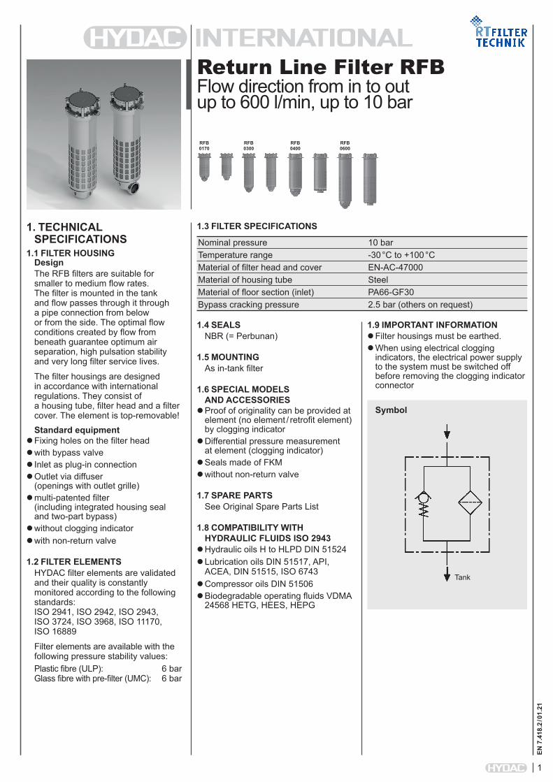
1.1 FILTER HOUSINGDesignThe RFB filters are suitable for smaller to medium flow rates. The filter is mounted in the tank and flow passes through it through a pipe connection from below or from the side. The optimal flow conditions created by flow from beneath guarantee optimum air separation, high pulsation stability and very long filter service lives.
The filter housings are designed in accordance with international regulations. They consist of a housing tube, filter head and a filter cover. The element is top-removable!Standard equipment
Fixing holes on the filter head with bypass valve Inlet as plug-in connection Outlet via diffuser
(openings with outlet grille) multi-patented filter
(including integrated housing seal and two-part bypass)
without clogging indicator with non-return valve
1.2 FILTER ELEMENTSHYDAC filter elements are validated and their quality is constantly monitored according to the following standards: ISO 2941, ISO 2942, ISO 2943, ISO 3724, ISO 3968, ISO 11170, ISO 16889
Filter elements are available with the following pressure stability values:Plastic fibre (ULP): 6 bar Glass fibre with pre-filter (UMC): 6 bar
1.4 SEALSNBR (= Perbunan)
1.5 MOUNTINGAs in-tank filter
1.6 SPECIAL MODELS AND ACCESSORIES
Proof of originality can be provided at element (no element / retrofit element) by clogging indicator
Differential pressure measurement at element (clogging indicator)
Seals made of FKM without non-return valve
1.7 SPARE PARTSSee Original Spare Parts List
1.8 COMPATIBILITY WITH HYDRAULIC FLUIDS ISO 2943
Hydraulic oils H to HLPD DIN 51524Lubrication oils DIN 51517, API,
ACEA, DIN 51515, ISO 6743Compressor oils DIN 51506 Biodegradable operating fluids VDMA
24568 HETG, HEES, HEPG
1.3 FILTER SPECIFICATIONS
Nominal pressure 10 bar Temperature range -30 °C to +100 °C Material of filter head and cover EN-AC-47000 Material of housing tube Steel Material of floor section (inlet) PA66-GF30 Bypass cracking pressure 2.5 bar (others on request)
1.9 IMPORTANT INFORMATION Filter housings must be earthed. When using electrical clogging
indicators, the electrical power supply to the system must be switched off before removing the clogging indicator connector
RFB 0170
RFB 0300
RFB 0400
RFB 0600
Symbol
Tank
2
EN 7
.418
.2 / 0
1.21
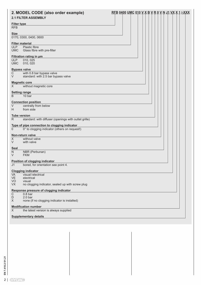
RFB 0400 UMC 010 V X B V R 0 V N J1 VX X 1 /-XXX
Filter typeRFB
Size0170, 0300, 0400, 0600
Filter materialULP Plastic fibre UMC Glass fibre with pre-filter
Filtration rating in µmULP 010, 025 UMC 010, 020
Bypass valveC with 0.8 bar bypass valve V standard: with 2.5 bar bypass valve
Magnetic coreX without magnetic core
Setting rangeB 10 bar
Connection positionV centrally from belowH from side
Tube versionR standard: with diffuser (openings with outlet grille)
Type of pipe connection to clogging indicator0 0° to clogging indicator (others on request!)
Non-return valveX without valve V with valve
SealN NBR (Perbunan) V FKM
Position of clogging indicatorJ1 bored, for orientation see point 4.
Clogging indicatorVA visual / electrical VE electrical VO visual VX no clogging indicator, sealed up with screw plug
Response pressure of clogging indicatorC 0.8 bar D 2.0 bar X none (if no clogging indicator is installed)
Modification numberX the latest version is always supplied
Supplementary details
2. MODEL CODE (also order example)2.1 FILTER ASSEMBLY
3
EN 7
.418
.2 / 0
1.21
UMC-0010-xxx-xxxx-x-N-RT /-XXX
Filter materialULP, UMC
Filtration rating in µmULP 0010, 0025 UMC 0010, 0020
RT code
SealN NBR (Perbunan) V FKM
Packaging
Supplementary details
2.2 REPLACEMENT ELEMENT
3. FILTER CALCULATION / DIMENSIONING3.1 PERFORMANCE CURVES FOR FILTER ASSEMBLY
The total performance curves with element UMC ... apply to mineral oil with a density of 0.86 kg/dm³ and a kinematic viscosity of 30 mm²/s.
Diffuser with opening V 304.5 202.5 168 269.5 – 3.2
RFB0300
Diffuser with opening H 472.5 296.5 262 – 447450
3.9
Diffuser with opening V 454.5 278.5 244 419.5 – 4.0
Housing closure V Housing connection H
Mounting element e. g.:Cyl. scr. ISO4762-M10x25-8.8Recommended torque 25 +5 Nm (when specified standard part is used with steel as material for the flange)
Torque 20 +5 Nm
Ø D1
Ø d2
4x Ø k
Ø d1
OUT
IN
OUT
IN
Ø D1
B
J1 connection for differential pressure indicator (e. g. VE, VA, VO)
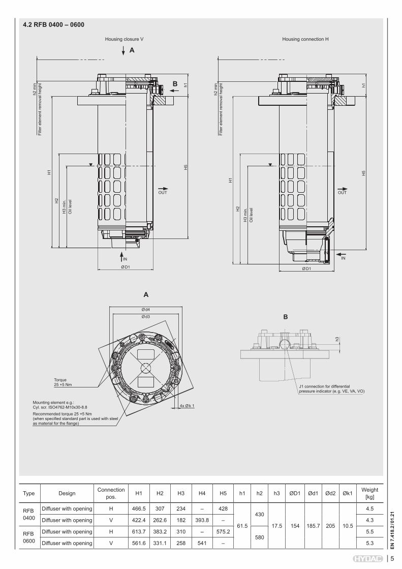
Diffuser with opening V 422.4 262.6 182 393.8 – 4.3
RFB0600
Diffuser with opening H 613.7 383.2 310 – 575.2580
5.5
Diffuser with opening V 561.6 331.1 258 541 – 5.3
Filte
r ele
men
t rem
oval
hei
ght
Filte
r ele
men
t rem
oval
hei
ght
h2 m
in
h2 m
in
Oil
leve
l
Oil
leve
l
OUT
IN
Housing closure V Housing connection H
Mounting element e.g.:Cyl. scr. ISO4762-M10x30-8.8Recommended torque 25 +5 Nm (when specified standard part is used with steel as material for the flange)
Torque 25 +5 Nm
Ø d4
Ø d3
4x Ø k 1
J1 connection for differential pressure indicator (e. g. VE, VA, VO)
h3
h1h1
H5
H5
H1
H1
H2
H2
H3
min
.
H3
min
.
Ø D1Ø D1
IN IN
OUT
6
EN 7
.418
.2 / 0
1.21
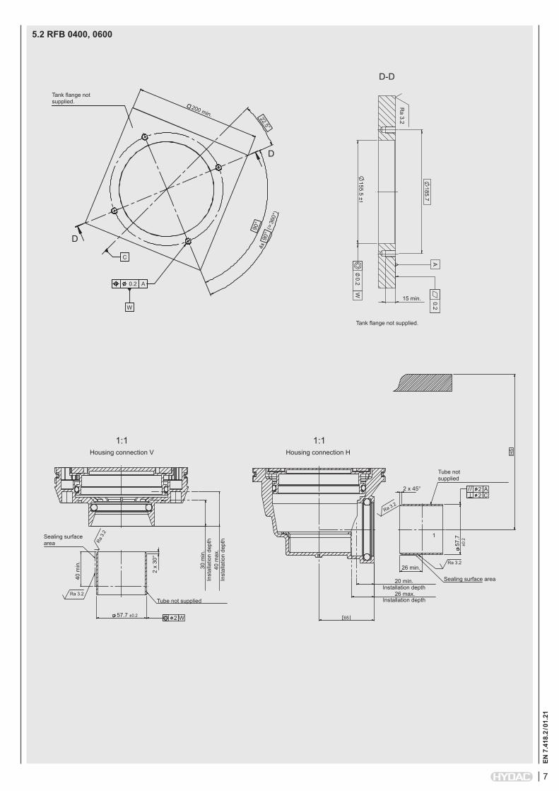
5. SPECIFICATIONS FOR THE TANK FLANGE1. In the filter mounting interface, the tank flange should have a maximum flatness of 0.2 mm
and a maximum roughness of Ra 3.2 µm.2. In addition, the mounting interface should be free from damage and scratches.3. The fixing holes of the flange must be blind, or stud bolts with threadlocker must be used
to fix the filter. As an alternative, the tank flange can be continuously welded from the inside.4. Both the tank sheet metal and the filter mounting flange must be sufficiently robust
so that neither deform when the seal is compressed during tightening.
Tank flange not supplied.
Tank flange not supplied.
Housing connection V Housing connection H
Inst
alla
tion
dept
hSealing surface area
Sealing surface area
Tube not supplied
Tube not supplied
Ra 3.265
Ra 3.2
Ra 3.2
Inst
alla
tion
dept
h40
max
.
30 m
in.
40 m
in.
2 x
30°
2 x 30°
Ra 3
.2
Installation depth
Installation depth
35 ±0.2
35 ±0.2
2
22
W
AC
180
140 ±10.2
0.2
□ 200 min.
15 min.
4x 90° (= 360°)
4x M100.2 A
W
C
90°
22.5
°
A
W
Ra 3.2
25 min.
30 min.
1
30 max.
H5
H5
5.1 RFB 0170, 0300
D
D
1:1 1:1
D-D
7
EN 7
.418
.2 / 0
1.21
5.2 RFB 0400, 0600
200 min.
D
D
Tank flange not supplied.
4x 9
0° (
= 360
°)
90°
22.5°0.2 A
C
W
Tank flange not supplied.
185.7
155.5 ± 10.2
0.2
15 min.
A
W
Ra 3.2
D-D
Housing connection V Housing connection H
Inst
alla
tion
dept
hSealing surface area
Sealing surface area
Tube not supplied
Tube not supplied
Ra 3.2
65
Ra 3.2
Ra 3.2
Inst
alla
tion
dept
h40
max
.
30 m
in.
40 m
in.
2 x
30°
2 x 45°
Ra 3
.2
Installation depth
Installation depth
57.7 ±0.2
57.7
±0
.2
2
22
W
AC
20 min.
26 min.
1
26 max.
H5
1:1 1:1
8
EN 7
.418
.2 / 0
1.21
NOTEThe information in this brochure relates to the operating conditions and applications described. For applications or operating conditions not described, please contact the relevant technical department. All technical details are subject to change.