e G)NNA STATIQN UNIT ¹a COi;IPLETED ROCHESTER GAS AND ELECTRIC CORP R&XbN GINNA STATION CONTROLLED COPY NUMBER PROCEDURE NO. M-32.2 REV. NO. 7 DB-50 REACTOR TRIP CIRCUIT BREAKER INSPECTION MAINTENANCE AND TEST TECHNICAL REVIEW PORC REVIEW DATE MAR 2 7 '985 QC R EW PLANT S ERINTENDENT APR 02!9"„5 EFFECTIVE DATE QA~ NON-QA CATEGORY 1.0 REVIEWED BY: ~ THIS PROCEDURE CONTAINS 35 PAGES SCO+X+0078 860407 PDR ADOCK 05000244 P PDR
Transcript
e G)NNA STATIQNUNIT ¹a
COi;IPLETED
ROCHESTER GAS AND ELECTRIC CORP R&XbN
GINNA STATION
CONTROLLED COPY NUMBER
PROCEDURE NO. M-32.2 REV. NO. 7
DB-50 REACTOR TRIP CIRCUIT BREAKER INSPECTION
MAINTENANCE AND TEST
TECHNICAL REVIEW
PORC REVIEW DATE MAR 2 7 '985
QC R EW PLANT S ERINTENDENT
APR 02!9"„5EFFECTIVE DATE
QA~ NON-QA CATEGORY 1.0
REVIEWED BY: ~
THIS PROCEDURE CONTAINS 35 PAGES
SCO+X+0078 860407PDR ADOCK 05000244P PDR
M-32.2'1
M-32.2
DB-50 REACTOR TRIP CIRCUIT BREAKER INSPECTION
MAINTENANCE AND TEST
1.0 PURPOSE
To provide instructions to perform inspection,maintenance and test of DB-50 Reactor Trip andReactor Trip Bypass Breakers.
2.0
2 '
REFERENCES:
Westinghouse switchgear division instruction book1B-33-850-3C instructions for DB-50, DBF-16 andDBL-50 air circuit breakers.
2 '
2 '
2 '
2.5
2.6
2 '
Westinghouse Technical Bulletin NSD-TB-83-02, Rev. 1,dated September 13, 1983.
Maintenance program for DB-50 reactor .trip switchgearrevision 0, October 14, 1983.
NRC generic letter 83-28.
November 23, 1984 NRC request for additionalinformation concerning generic letter 83-28.
W FCN RGE 0-40503 shunt coils RT switchgear.
RG&E's 2/28/84 response to NRC's request forsupplemental information concerning generic letter83-28.
3.0 INITIALCONDITIONS:
3.1 Notify QC prior to starting the job, for assignmentof Inspection Personnel.
3 ' Plant may be in any mode of operations.
M-32.2:2
3.3 The Shift Supervisor and Head Control Operator shallbe notified just prior to any inspection or maintenanceon the reactor trip system.
Shift Supervisor
Head Control Operator
4.0
F 1
PRECAUTIONS:
Obtain replacement parts in accordance with A-801..
5.0 INSTRUCTIONS:
5.1 Indicate here and on front cover of procedure thebreaker to be worked on. N/A other spaces not .
required.
5.2l.
5 .'2 . 1
Bypass
Remove from Service:
At power (mark N/A if not at power).
Spare
5 ~ 2 ~ 1 ~ 1 Establish communications between Control Room , RelayRoom , and Reactor Trip Breaker .
5.2 '.2 Electricians place reactor trip bypass breaker intoposition to bypass breaker under going maintenance,and rack into the "Fully Racked In" position. Verifythat 20 AST and 20 ET indicating lights are illuminatedat breaker panel.
5.2.1.3 "Close" By-pass Breaker by actuation of resetpushbutton switch in reactor logic test cabinet of
indicating lights are NOT illuminated.
5 '.1.4 "Trip" By-pass Breaker by actuation of pushbuttontrip,.switch in .reactor logic test cabinet of the
indicating lights are illuminated.
M-32.2:3
5.2.1.5 "Close" By-pass Breaker by actuation of resetpushbutton switch, and verify that 20 AST and 20 ETindicating lights are not .illuminated.
5 '.1 ~ 6 "Trip" Reactor Trip Breaker to be worked on byactuation of pushbutton trip switch in the reactorlogic test cabinet for that train.
5.3 Notify I/C shop foreman to perform PT-32.5, ReactorTrip Breakers "A" & "B" Train Response Time Testing.
5 ' Hold breaker in accordance with A-1401 Station HoldingRules, if applicable.
5.5
5.5.1
5.5 '.1
~Test inTri Bar Fi . 1
Energize the undervoltage coil from a dc source, atthe rated voltage, with a capacity of at least 0.25
~ amperes.
5.5.1 ~ 2
5.5.1.2.1Mechanical trip force test.Raise and lower the trip bar by hand to assure thatit does not bind; i.e., it should feel like a freeweight. Close the breaker and initiate a trip bypushing down the positioning lever. Log results ondata sheet.
5. 5. 1. 2. 2 Close the breaker manually.
5.5.1.2.3 Add weights to weight stand via bear'ing arrangementpulling vertically on the trip bar. Record the totalweight (weights and weight stand) added to the bar.The trip force should be 870 grams or less. Logresults on data sheet.
5. 5. 1. 2. 4 The fo 1 1 owing steps are to establish that there ismargin in the trip force of the undervoltage device.
M-32.2:4
BieaRC i@stag
gQ wqiP4~pttb54 ~
U v I (Fv
l�app(TioHha
m&GN7ppOFO yZRf a CHEWTg)PPW'6 foACE
M-32. 2 5
5.5.1.2.5 Load the trip bar (see attached drawing) with aweight of 460 grams minimum to 560 grams maximum.
5.5.1.2.6 Manually close the breaker.
5.5.1.2.7 De-energize the undervoltage coil and observe andthat the breaker trips. If the breaker does nottrip, it is an indication that the undervoltagedevice requires cleaning and/or lubrication orreplacement. Log results on data sheet.
5.5.1.2.8 Re-energize the undervoltage coil and manually closebreaker.
5.5.1 ~ 2 ' Apply 70 VDC + .5v to shunt trip circuit and applytrip signal. Repeat 5 times. If breaker -fails totrip notify I&C Supervisor. Log results on data sheet.
5. 5. 1. 2. 10 Remove the weights.
5 '
5.6.1
~Cleanin
When cleaning is required, it should consist ofwiping with paper towels or lint-free cloths toremove dust and dirt. In some cases, brushing with amedium bristle or stiff bristle brush may benecessary. Do not use a wire brush. Brushing shouldbe supplemented by vacuuming.
If sticky or gummy substances are present, a mildsolvent such as Stoddards Solvent may be used. Thepreferred method is to apply the solvent by dampeninga paper towel and wiping the affected area. Inconfined areas or in cleaning small parts, apply thesolvent sparingly using a small brush. Do not applythe solvent to coils, wires, or other electricallyinsulated parts.CAUTIoN: Keep sparks and flames away. Do not breathe
large c[uantities o f vapor.'void excesscontact with skin.
M-32.2:6
step 5.6.1 cont.
Except for use in cleaning of removed arc chutes,avoid the use of high pressure air. Dirt, grit orother substances can be driven into spaces betweenparts creating friction, which would not otherwiseoccur. Log results on data sheet.
5.7
5.7.1 0 eratin Mechanism Fi . 1
NOTE: This test will require two persons. Sincethe Undervoltage Trip Attachment (UVTA) isdeenergized itmust be temporarily restrainedin the reset position. One person will berequired to hold back the UVTA reset lever(Figure 4) by means of a wire or nylon cord(12" minimum) . The other person willperform the following:
5.7.F 1
5.7.1.2
CAUTION: Keep hands and tools well away from movingparts of the breaker to avoid personalinjury or equipment.
Rotate the manual ope,matin'g handle ~slowl in aclockwise direction to move the contacts toward theclosed position.Observe whether all moving parts are in properalignment and move freely.
5.7.1.3
5.7.1.4
Be sure that the contacts are clean and properlyaligned.
If the contacts are in alignment and all parts movefreely, continue the clockwise rotation until thebreaker is latched.
M-32.2:7
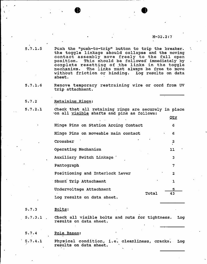
5.7.1 ~ 5 Push the "push-to-trip" button to trip the breaker.the toggle linkage should collapse and the movingcontact assembly move freely to the full openposition. This should be followed'mmediately bycomplete resetting of the links in the togglemechanism. The links must always be free to movewithout friction or binding. Log results on datasheet.
5.7.1.6 Remove temporary restraining wire or cord from UVtrip attachment.
5 ' '
5.7.2.1Retainin Rin s:
Check that all retaining rings are securely in placeon all visible shafts and pins as follows:
Hinge Pins on Station Arcing Contact
Hinge Pins on moveable main contact
Crossbar
Operating Mechanism
Auxiliary Switch Linkage "
Pantograph
Positioning and Interlock Lever
Shunt Trip Attachment
Undervoltage Attachment
Log results on data sheet.Total 43
5.7.3 Bolts:
5.7.3.1 Check all visible bolts and nuts for tightness. Logresults on data sheet.
5.7.4 Pole Bases:
5.7 ~ 4 ~ 1 Physical condition, i.e. cleanliness, cracks. Logresults on data sheet.
M-32.2:8
5.7.5
5.7.5 '
Arc Chutes:
While a .somewhat pitted, mottled and sooty appearanceis normal, be alert for heavy erosion or brokenplates. Damaged chutes should be replaced. Logresults on data sheet.
5.7.6
5.7.6.1
Arcin & Main Contacts Fi . 1
Check for roughness, spawling, galling 6 distortion.Log results on data sheet.
NOTE: Some tarnishing is normal due to silveroxides and sulfides. Dress or replace persec. V-A-l.
5.7.6 ' The DB-50 arcing contact should touch first on closing,open last on opening. Contact pressure on the mainsis maintained by adjusting gap G to 050-093 inches.This gap is adjusted by removing the cross BHR andscrewing the insulting link in or out on the stud.Be sure to tighten the lock nuts after eachadjustment. Log results on data sheet.
CAUTION: Do not over-adj ust as this will cause thecontact springs to compress to the solidposition and thus increase the closingeffort.
5.7.6.3 Check for over-adjustment by prying the stationaryarc tips open to at least 1/16 — inch gap. Logresults on data sheet.
5.7.6.4 Re-install the three arc chutes.
H-32.2:9
4o
SHUNT TRIPATTACHNENTWZTH U V,ATTACHNENTREMOVED
MECHANZSN,
STLTICPCLRY~aCONTACT
~IPfKB ST(Xips
Er
rr ~
"LCWER COll.~r>MILL
GASCON.C83'
WAX!LlARYM4lHC KQCT
MOVWOCCNT4CTHHQQ
LCAQ\ Si&g SOT
LPP+M C~LTERMINAL
NOSCLENClQ
BREAKER SHOWN ZN CLOSED POSITZON
,CLOSING SQLENIQD - CONSTRUCTION DETAILS
M-32.2:10
g,tIq ~~ ~~ ~~ ~
aoeeeQ
I '
(
l+I
'
9 lg
a
J
II
CQ T QL RELAy" ADJUSTNENT AND CQNSTRUCTIQlP5ETAZLSH-32.2:11
';~)~i RtP PiN CN RELAY
,~'1
SOLENOID!HAGUE,i l.WAil
~".V= w
i
'
Ii
i
RELAY RELEASEARM
t E.VER p~'~I
CLOSlNG SOLENOIDMoviNG CCeE.
OPERkflVO Olt:54
IIEI JY VOI O~5roP 5LJRItiCE 0
REL.E45EL.EVER
CovERl59
P4OVIIIO CONT. L..P >55R.P, I 95
5TaTIORaRV COIIT. L..P. IOO~A.P. I4$
A~T~4IC
I ~ » ~ ~I
I
i ~
~'V ~~~a
5t » SO'» ~ COl'ti I
1RC It'» TE /CR 5 ~ C .'vgt
A
0
M-32.2:12
5.7.7
5.7.F 1
Insulatin Link Fi . 1
Check for cleanliness, chips, cracks, and tightnessof locknut. Log results on data sheet.
5.7.8 w~irin
5.7.8.1 Check condition of insulation and terminations. Logresults on data sheet.
5.7.9
5,7.9.1
Closin Solenoid Fi . 2
Check for loose bolts. Log results on data sheet.
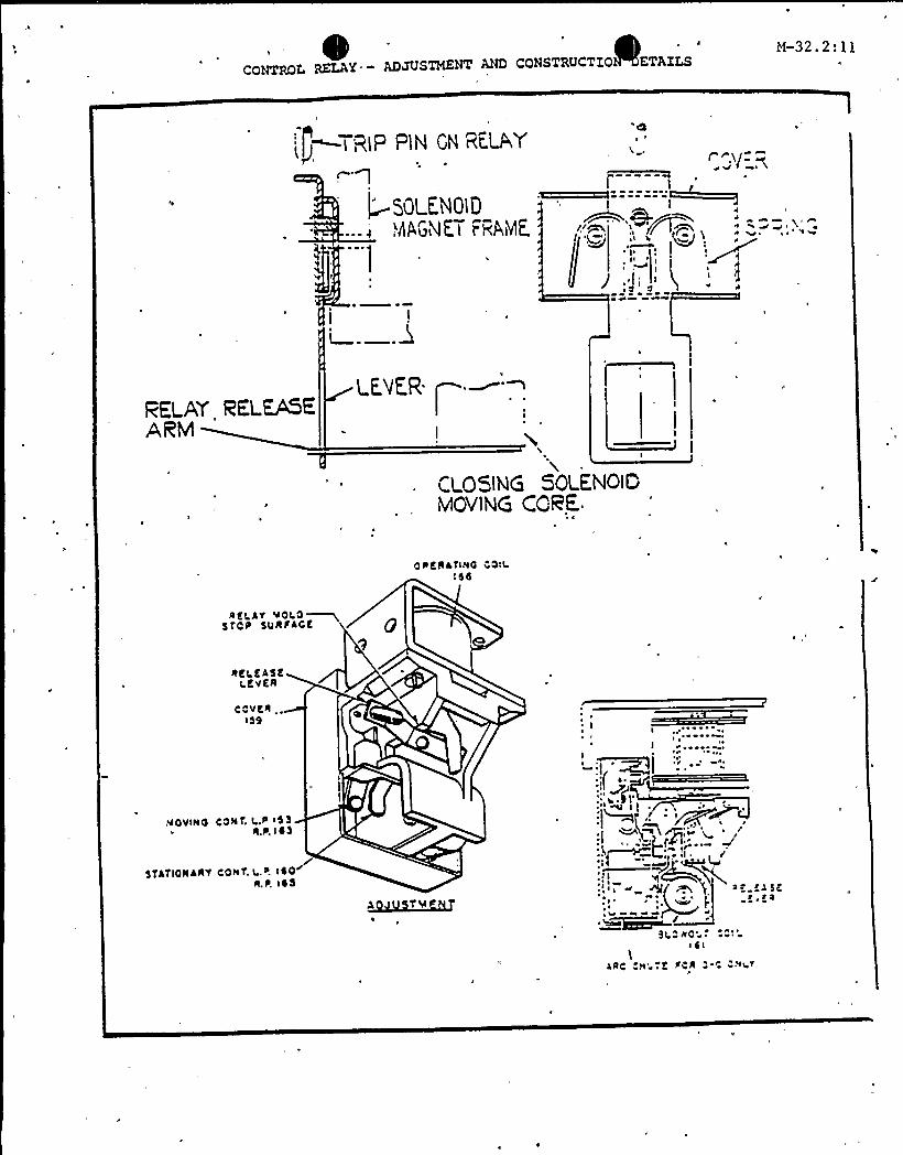
5.7.10 Control Rela Fi . 3
5.7. 10 ~ 1 Examine contacts for burning wear '& pitting; replaceif necessary. Log results on data sheet.
5.7.11
5.7.11.1
Undervolta e Tri Attachment UVTA Fi . 4
With the UV attachment deenergized but held in thereset position by a temporary restraining wire orcord on the reset lever, (per activity 2a) thebreaker is closed manually. Then, the temporaryrestraint is ~slowl released*, allowing UV attachmentto perform the breaker trip function before the resetlever comes to rest. Monitor for unhesitant, smoother,positive, snap-action of the UV attachment, and breakertrip. Log results on data sheet.
*CAUTION: Be sure to hold the very end o f therestraining line and keep .both hands, aswell as equipment, away from crossbar whichwill snap back as breaker trips.
5.7.11.2 If lubrication of UV Attachment is considerednecessary, lubricate per Attachment l. (NA otherwise)
5.7.11.3 With UV coil energized inspect for visible.gap betweenUVTA trip level and breaker trip bar with breakerhalf-way closed. Log results on data sheet.
M-32.2e13
5.7.11.4 Dro out Volta e Test:
5.7.11.4.1 Connect a d.c. power supply (adjustable 10-125V,rated 5 amps at 125V) and a voltmeter (+ 1% accuracy)across UVTA coil by means of test leads acrossSECONDARY CONTACT terminals. 'pply rated voltage andclose breaker manually.
NOTE Obtain "Reference" dropout voltage fromprevious completed procedure for thisbreaker and log on data sheet.
5.7.11.4.2 Reduce voltage to within 5-6 volts of last recordeddropout voltage (on very first test make quick trialrun) and then decrease voltage ~slowl (15 sec/volt)until breaker trips. Repeat test twice and average thethree readings. Record the average dropout voltage on
KZtest on this UTVA, then the measurement also becomesits "REFERENCE" dropout voltage.
5.7.11.4.3 ~Re lace UTVA under the following criteria, based on"after lubrication" data: a) Dropout voltage isgreater than 75 VDC and less than 37.5 VDC. b)Dropout voltage differs by more than + 5 volts fromthe "REFERENCE" voltage.
Replaced Not Replaced
5.7.11.5 Check mounting bolt tightness.
5.7. 12
5.7.12.1
Shunt Tri Attachment Fi . 5)
With the breaker in the open position, manually pushthe moving core against the stationary core (shouldfeel free and non-binding) and rotate the breakerhandle to the closed position. The breaker should betrip free. (Trip lever will raise trip bar whichprevents 'closing of breaker.) Log results on datasheet.-
5.7 ~ 12.2, The trip lever of the shunt trip should have from1/32 to 1/8 inch clearance to the trip bar. Logresults on data sheet;
M-32.2:14
5.7.12.3 Check mounting bolts. Log results on data sheet.
5.7.12.4\
Close breaker and apply 70 VDC to shunt coil ofclosed breaker via SECONDARY CONTACT Terminals. Ifbreaker does not trip, replace SHUNT TRIP attachment.Log results on data sheet.
tf-32.2:15
/I 1
/
IIIIIrI
ADJUSTABLE RESET LEVER
CROSS BAR
/x~A/ / LATCH
FRAME COILQo
MOVING CORE
SELF LOCKINGSCREW
COVER~ROD
,./r .~nri R&~
r rg
«C
STATIONARYCORE
TRIP /SPRING
TRIPLEVER
- Undervoltage Trip Attachment - Construction Details
~ ) ~
SHUNT TRIP ATTACHHENT LOCATION AND CONSTRUCTION DETAILS
I'1
))iJ
ii~ (
~,
Iy 'jIi
St4fiOII44TCO(t C
CO( I.F00 C ~ 4.5I <
VOV 514~ CO((K
~ I 7 $ 4(t
~(
I(0(
5
I I
I II II II I~ II II I
5 T5IL5t ~ 57 I f'Tfi
M-32.2 17
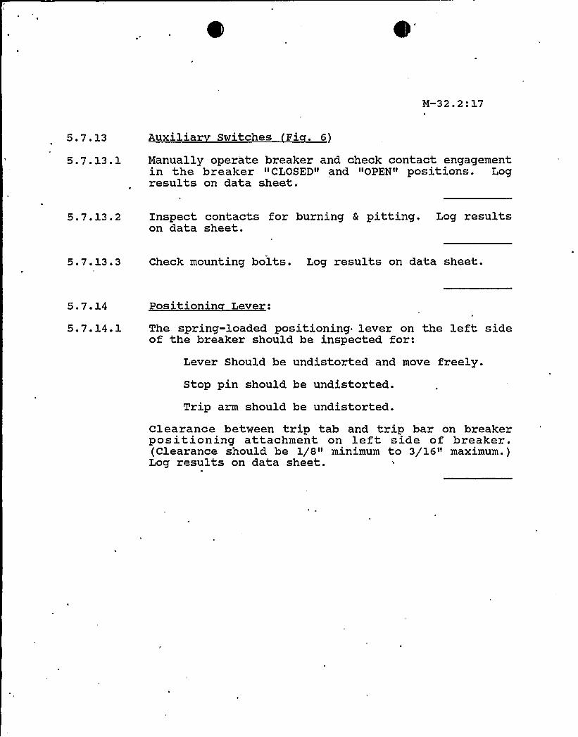
5.7.13 Auxiliar Switches Fi . 6)
5.7. 13. 1 Manually operate breaker and check contact engagementin the breaker "CLOSED" and "OPEN" positions. Logresults on data sheet.
5.7.13.2 1nspect contacts for burning & pitting. Log resultson data sheet.
5.7.13.3 Check mounting bolts. Log results on data sheet.
5.7.14
5 ' '4 '
Positionin Lever:
The spring-loaded positioning lever on the left sideof the breaker should be inspected for:
Lever Should be undistorted and move freely.Stop pin should be undistorted.
Trip arm should be undistorted.Clearance between trip tab and trip bar on breakerpositioning attachment on left side of breaker.(Clearance should be 1/8" minimum to 3/16" maximum.)Log results on data sheet.
M-32.2:18
AUXILIARY SWITCH CONSTRUCTION DETAILS
~i5~ i ~ aCa COvCa5iit+ 0gtv{O
COOf ICEt ro4(0
C01fiCt~»<O<0i
C4$ t ~ttOe i CO> C+
M-32.2:19
5.7.15
5.7.15 '
Cell Interlocks:
Depress the positioning interlock lever on left sideof breaker; closed breaker should trip.
5.8 Breaker Me er Readin s:
5 ~ 8 ~ 1 With breaker open measure resistance between eachphase to ground and phase to phase, using 500 voltmegger. Log results on data, sheet.
5.8.2 With breaker closed measure resistance between eachphase to ground and phase to phase, using a 500 voltmegger. Log results on data sheet.
5 ' ~Testin
5 '.1 Tri Bar Fi . 1
5.9.1.1 Energize the undervoltage coil from a dc source, atthe rated voltage, with a capacity of at least 0.24amperes.
5.9.1.25.9.1.F 1
Mechanical trip force test.Raise and lower the trip bar by hand to assure thatit does not bind; i.e., it should feel like a freeweight. Close the breaker and initiate a trip bypushing down the position lever. Log results on datasheet.
5.9.1.2.2 Close the breaker manually.
5.9.1 ' ' Add weights to weight stand via bearing arrangementpulling vertically on the trip bar. Record the totalweight (weights and weight stand) added to the bar.The trip force should be 870 grams or less. Logresults'n. data sheet.
5.9.1.2.4 The following steps are to establish that there ismargin in the trip force of the undervoltage device.
l
M-32.2:20
5.9.1.2.5 Load the trip bar (see ~ attached drawing) with aweight of 460 grams minimum to 560 grams maximum.
5. 9. 1. 2. 6 Manually close, the breaker.
5.9.1.2.7 De-energize the undervoltage coil and observe andthat the breaker trips. If the breaker does nottrip, it is an indication that the undervoltagedevice requires replacement. Log results on datasheet.
5.9.1.2.8 Re-energize the undervoltage coil and manually closebreaker.
5.9.1.2.9 Apply 70 VDC + .5v to shunt trip circuit and applytrip signal. Repeat 5 times. If breaker fails totrip notify I&C Supervisor. Log results on data sheet.
5.9.1.2.10 Remove the weights.
5.10
5.10.1
Function Check Prior to Returnin to Service:
Check for any tools and equipment left in breaker.
5.10.2 After inspection and maintenance, perform a finaloperational check of the UV Attachment and breakertrip action by closing the breaker either manually orelectrically, then tripped by de-energizing of the UVAttachment. Repeat this 10 times and document onattached data sheet.NOTE: This applies to post maintenance testing
and is not associated with PT or RSSP testprocedures.
5. 11 Switch ear Enclosure: (N/A this step if switchgearis alive and/or if maintenance.was on spare Rxbreaker. )
I
J
M-32.2:21
5.11.1 Inspect both the stationary portions of the main, aswell as, secondary disconnecting devices for abnormalwear and overheating. Discolorations of the surfaceis not harmful unless corrosion due to atmosphericconditions is sufficiently severe as to leave depositson the contact surfaces. Any deposits must be removedby rubbing with a clean cloth moistened with Stoddard'sSolvent, otherwise a new-contact has to be installed.Log results on data sheet.
5. 11 ~ 2 Remove dust fr'm buses, ~ connections, . supports,enclosure surfaces etc. using the methods outlined inSection III.
5.- 11 ~ 3 Check buses, primary connections and supports for tightbolts; also, check all secondary wiring connectionsat the terminal blocks. Log 'results on data sheet.
5 ~ ll~ 4 Inspect the positioning stop bracket and supportrails for signs of mechanical damage and corrosion.Log results on data sheet.
5.11.5E
Check breaker support wheels for free movement.Inspect cell interlock switches for distortion, freemovement and test for proper contact operation. Logresults on data sheet.
5.11.6 Megger test switchgear bus and wiring. Log results ondata sheet.
5.11.7 Place the breaker in the cubicle, place it in the"test" position, and close the breaker.
5.11.7.1 Depress the position lever, and the breaker shouldtrip.
5.11.7.2 Try closing the breaker between the "test" and"connected" position; it should not close.
M-32.2:22
Remove hold on breaker.
Notify Results and Test supervisor of maintenanceh
~brea er using test procedures PT-32.5 (Reactor TripBreakers "A" & "B" Train Response Time. Testing).
I&C Supervisor and the Electric Shops Foreman reviewthe results of this procedure and evaluate them tothe previous breaker maintenance results.COMMENTS:
Electric Foreman
I&C Supervisor
COMPLETED BY:
DATE COMPLETED:
ELECTRICIAN FOREMAN:
Q. C. SUPERVISION:
RESULTS & TEST SUPERVISION:
I&C SUPERVISOR:
POST PORC REVIEW DATE:
H-32.2:23
El
IV LUBRICATION
17180:4 36 Rev.'0
Ol/TA FIELD Li/BRlCA / /ONH-32.2:2EI
~tp EKHGKC7
bf)TGH . SPACER/ I /h'S/OE p'OUTJ/OE
t *
ZW.CHSPEW'y
LAZCh'~., LLSU]VFACE'5
LATCH GOIDE PIN
L//DC'/hl
8eiVor PIA TRtP SeemENLARGE'0 Y/El/l/ A
'NLARGED
j/lEN'B'-LuBRICArE
SuRPACZSINO/ CA TE O i@I TH
637O ( |"
A',QO5 ~a EHLAR'S~DV/EW 8
hI,,
L"
Rev. 0
l
H-32,2:25
IV Lubrication
The only points requiring periodic re-lubrication on the DB-50, as
configured for reactor trip service, are located on the UV trip attach-
These should be lubricated with 5370IGM lubricant {see "C" below)
as follows:
Lubrication Points "" Referring to the attached sketch (Fig. 8), the
following points require periodic lubrication:
1
2
3
4
5
Latch to latch springLatch loop to latch guide-pinLatch to latch pin
Latch pivot pinPin running through the trip spring
NOTE: The latch pin, latch guide pin, latch pivot pin, and the tripspring pin are to be lubricated at all points along their lengthswhere there is existing or potential metal-to-metal contact,including ends where pins pass through support brackets. In
addition, lubricant should be applied to bracket. inside surfaces
which may contact latch pivot pin ends.
Lubrication Techni ues
1. The lubricant is to be applied using the container and dispensing tube
provided with the Lubrication Kit. Lubricant handling and applicationtechniques are further described in the Instruction Sheet accompanying
the Kit, and reproduced on following pages.
2. The lubrication may be performed without'removing the UVTA from itsmounting. However, special care is required to reach all lubricationpoints by varying the direction of the application bottle dispensingtube.
17180:438 Rev. 0
H-32.2:26
3. Dispense drops of lubricant at designated points by placing tip of
dispensing tube at the appropriate location and gently raising the
container.
4. Apply lubricant liberally at all points, and manually exercise the
mechanism during and following lubricant application. This manual
exercising is accomplished by first blocking the Breaker. partiallytowards the closed position (so that the UTVA reset lever isreleased). Exercise the device by manipulating the reset lever.
Lubrication Precautions
1. The lubrication mixture must be kept thoroughly mixed prior to and
throughout the procedure by vigorously shaking the containeroccasionally.
2, Place a cloth beneath the UVTA while applying lubricant to collectover-shoot and run-off lubricant.
3. Additional precautions on handling of the lubricant are provided inthe Instruction Sheet accompanying the Lubrication Kit. (See attached
procedure on following pages)
4. Intervals between relubrication of the UVTA should not exceed 200
Breaker operation cycles. (Breaker open then Breaker closed equals
one cycle.)
B. In cases where a solvent has been used to clean a circu'it breaker so thatoriginally applied lubrication may have been removed or in cases where a
circuit breaker shows signs of sluggishness or friction, lubricant 53701GW
latch surfaces. Upon completion of lubrication, the'.breaker'hould be
closed and tripped several times.
CAUTION: NEVER USE 53701GW LUBRICANT ON CURRENT CARRYING PARTS.
17180:439 Rev. 0
H-32.2:27
C. Lubrication Materials The only UVTA lubricant. approved by Westinghousei's a composition of a finely ground and purified natural ore of molybdenum
disulfide and iso-propyl alcohol. It is prepared by mixing 5 parts by
weight of this lubricating grade molybdenum disulfide with 3 parts by
we gi ht of commercial grade iso-propyl alcohol. This lubricant is identi-fied as Westinghouse Spec 53701GW, Rev. C. For better flow characteris-
tics, the mix ratio has been revised slightly from earlier batches. Any
on-hand supplies of lubricant to an earlier Revision of this Specificationmay be used providing lubricant application is closely monitored to ascer-
Wtain that adequate flow is attained.
This lubricant, including handling and dispensing accessories, iscommercial ly available thru:
NOTE: The solvent and the liquid portion of the lubricant are flammable.
Proper ventilation should be maintained. Keep away from sparks-, fireor flame.
1. Thoroughly mix contents in glass container of lubricant by shaking
vigorously for two minutes.
2. Pour lubricant into plastic container and attach the dispensing tube
assembly. Tighten the tube assembly on the container. Pull gently on
tube to make sure it is fully extended.
3. Oispense drops of lubricant at designated points by placing tip ofdispensing tube at appropriate location and raising lubricantcontainer to the vertical position. Squeeze container gently ifnecessary.
It may be desirable to try out the dispenser to get a feel for the
position required to dispense one drop. The closer the lubricantcontainer is to a vertical position above the tube tip, the faster theflow. By lowering the container to the horizontal position the flowof lubricant can be stopped.
4. While using the lubricant, shake the container about every minute tokeep the lubricant from settling out.
17180:441 Rav A
y<-Z2.2:29
5. If the contents have been left standing for longer than 5 minutes, itwill require shaking for two minutes.
After using the dispenser for lubrication'and if lubricant is to be
stored overnight or longer, the following storage steps should be
taken.
a) Remove dispensing tube assembly from container and poor lubricantinto original container and seal with cap.
b) Wipe excess lubricant from outside surface of dispensing tube witha clean towel or cloth.
c) Add 1/4 to 1/2 inch of solvent to dispensing container and attachdispensing tube assembly to top of container, then shake.
d) 1nvert container to wash lubricant from dispensing tube. 12 to 15
drops of solvent should clean tube. The solvent is flammable and
should be dispensed into a suitable container used for storage offlammable waste solvents. Remove dispensing tube assembly,
discard excess solvent, and store the clean dispensing tube
assembly for future use.
e) Seal solvent container with original cap.
7. If tip of dispensing tube assembly becomes clogged it can usually be
cleaned by inserting a common pin into the tip opening to clear it.Repeat Sec. 6(c) and (d).
~C1ean-U
Lubricant can be removed from skin areas by using liquid hand cleaner and water.
NOTE: If lubricant does not dispense properly, clean„dispenser tube persection 6 and/or section 7. If lubricant still does not dispenseproperly, examine tube for damage and if damaged, replace dispenser tubeassembly, 693C500G03. If the dispenser tube assembly is satisfactory,replace container of lubricant with a new one.
1718D:4Qau h
M-32.2'30
DATA SHEET
REACTOR TRIP BREAKER BYPASS
WESTINGHOUSE DB-50 S/N
TYPE OF INSPECTION: ANNUAL SPECIAL
5.5.1 Trip Bar— Acceptable Unacceptable
5.5.1.2 Trip bar trip force grams
Loaded trip bar UV test Tripped Didn't tripLoaded trip bar shunt trip test
Acceptable
CORRECTIVE ACTIONS:
Unacceptable
5.6 Cleanliness—
CORRECTIVE ACTIONS:
Good Fair Poor
5.7.1 Operating MechanismUnacceptable
CORRECTIVE ACTIONS:
Acceptable
5.7.2 Retaining Rings
CORRECTIVE ACTIONS:
None missing One ormore missing(Identify)
e
M-32.2:31
DATA SHEET
Bolts— Tight Loose (Identify)CORRECTIVE ACTIONS:
Pole Bases— Good Poor
CORRECTIVE ACTIONS:
ARC Chutes:
CORRECTIVE ACTIONS:
No erosion or damage
Moderate erosion
Heavy erosion and/or damaged plates
Arcing and Main Contacts
Condition:
Alignment:
Good Fair Unacceptable
Acceptable Unacceptable
Gap: Phase A in. Phase B in. Phase C in.CORRECTIVE ACTIONS:
Insulating Links: Good Fair Poor
Wiring: Good
CORRECTIVE ACTIONS:
Fair Poor
M-32.2:32
DATA SHEET
Closing Solenoid Bolts:
CORRECTIVE ACTIONS:
Tight Loose
Control Relay Contacts:
CORRECTIVE ACTIONS:
Good Fair Poor
Undervoltage Trip attachment:
Action: Acceptable
Unacceptable
Acceptable after lube
Gap:
Bolt:Acceptable
Tight
Unacceptable
Loose
DROPOUT VOLTAGE TEST
Reference voltage: VDC
1st VDC 2nd VDC 3rd VDC
Average VDC
CORRECTIVE ACTIONS:
Shunt Trip Attachment:
Core Movement: Free Binding
Trip Free: Yes No
Trip Bar Clearance:Acceptable
Mounting Bolts: Tight
Acceptable
Loose
Not
M-32.2:33
DATA SHEET
SHUNT TRIP VOLTAGE TEST:
Acceptable
CORRECTIVE ACTIONS:
Not acceptable
5.7.13 Auxiliary Switches:
Contact Engagement:Unacceptable
Contact Pitting:Bolts: TightCORRECTIVE ACTIONS:
Good
Loose
Acceptable
Fair Poor
5 ' '4 Positioning Lever:Unacceptable
CORRECTIVE ACTIONS:
Acceptable
5.7.15 Cell Interlocks Tests:
Acceptable
CORRECTIVE ACTIONS:
Unacceptable
5.8 Breaker Megger Readings:
Breaker Open
Phase 1 — Phase 2
Phase 2 — Phase 3
Phase 2 — Gnd
Phase 1 — Phase 3
Phase 1 — Gnd
Phase 3 — Gnd
M-32.2:34
DATA SHEET
Step 5.8 cont.
Breaker Closed
Phase 1 — Phase 2
Phase 2 — Phase 3
Phase 2 — Gnd
Phase 1 - Phase 3
Phase 1 — Gnd
Phase 3 — Gnd
CORRECTIVE ACTIONS:
5.9.1 Trip Bar— Acceptable Unacceptable
5.9.1.2 Trip har trip force grams
Loaded trip bar UV test Tripped Didn't tripLoaded trip bar shunt trip test
Acceptable Unacceptable
CORRECTIVE ACTIONS:
5. 10 Function Check:
Manual test of UV Attachment UV operation verified 10times


![VARIABLE-SPEED DRIVE COMPRESSORS€¦ · ASHRAE Capacity [W] Tc=54.4°C, Tliq=32.2°C, Tsuc=32.2°C Evaporating temperature [°C] ASHRAE Displacement Voltage and frequencies (dual](https://static.documents.pub/doc/80x56/613c733e4c23507cb635640c/variable-speed-drive-compressors-ashrae-capacity-w-tc544c-tliq322c-tsuc322c.jpg)
![Zehnder ComfoWell 220 [dB] 5.9 10.2 11.1 16.3 14.8 32.2 25.8 28.1 1x end plate CW-P 220 + 2x attenuators CW-S 220 + 1x end plate CW-P 220 or mounting plate CW-M 220 Insertion loss](https://static.documents.pub/doc/80x56/5f0e08317e708231d43d4802/zehnder-comfowell-220-db-59-102-111-163-148-322-258-281-1x-end-plate-cw-p.jpg)


