20
IM2059 04/2014 REV01 FLEXTEC™ 450&650 CE OPERATOR’S MANUAL ENGLISH THE LINCOLN ELECTRIC COMPANY 22801 St. Clair Ave., Cleveland Ohio 44117-1199 USA www.lincolnelectric.eu
IM2059 04/2014 REV01
FLEXTEC™ 450&650 CE
OPERATOR’S MANUAL
ENGLISH
THE LINCOLN ELECTRIC COMPANY 22801 St. Clair Ave., Cleveland Ohio 44117-1199 USA
www.lincolnelectric.eu
English English I
THE LINCOLN ELECTRIC COMPANY
EC DECLARATION OF CONFORMITY FOR FLEXTEC™450 CE Manufacturer and technical documentation holder:
The Lincoln Electric Company
Address:
22801 St. Clair Ave. Cleveland Ohio 44117-1199 USA
EC Company:
Lincoln Electric Europe S.L.
Address:
c/o Balmes, 89 - 80 2a 08008 Barcelona SPAIN
Hereby declare that welding equipment:
Flextec™ 450 CE, including options and accessories
Product numbers:
K3065 (Product numbers may also contain prefixes and suffixes)
Is in conformity with Council Directives and amendments:
Electromagnetic Compatibility (EMC) Directive 2004/108/EC
Low Voltage Directive (LVD) 2006/95/EC
Standards: EN 60974-10 Arc Welding Equipment – Part 10: Electromagnetic compatibility (EMC) requirements, 2003 EN 60974-1, Arc Welding Equipment – Part 1: Welding Power Sources, 2005
CE marking affixed in ’11
Frank Stupczy, Manufacturer Dario Gatti, European Community Representative
Compliance Engineering Manager European Engineering Director Machines 03 March 2013 04 March 2013 MCD361a
English English II
THE LINCOLN ELECTRIC COMPANY
EC DECLARATION OF CONFORMITY FOR FLEXTEC™650 CE Manufacturer and technical documentation holder:
The Lincoln Electric Company
Address:
22801 St. Clair Ave. Cleveland Ohio 44117-1199 USA
EC Company:
Lincoln Electric Europe S.L.
Address:
c/o Balmes, 89 - 80 2a 08008 Barcelona SPAIN
Hereby declare that welding equipment:
Flextec™ 650 with CE marking and installed CE filter.
Product numbers:
K3060 and K3129 (Product numbers may also contain prefixes and suffixes)
Is in conformity with Council Directives and amendments:
Electromagnetic Compatibility (EMC) Directive 2004/108/EC
Low Voltage Directive (LVD) 2006/95/EC
Standards: EN 60974-10 Arc Welding Equipment – Part 10: Electromagnetic compatibility (EMC) requirements, 2007 EN 60974-1, Arc Welding Equipment – Part 1: Welding Power Sources, 2005
CE marking affixed in ’13 Frank Stupczy, Manufacturer Dario Gatti, European Community Representative
Compliance Engineering Manager European Engineering Director Machines 25 September 2013 1 October 2013
MCD390
English English III
12/05
THANKS! For having chosen the QUALITY of the Lincoln Electric products. Please Examine Package and Equipment for Damage. Claims for material damaged in shipment must be notified
immediately to the dealer. For future reference record in the table below your equipment identification information. Model Name, Code &
Serial Number can be found on the machine rating plate.
Model Name:
………………...…………………………….…………………………………………………………………………………………..Code & Serial number:
………………….……………………………………………….. …………………………………………………….……………..
Date & Where Purchased:
…………………………………………………………………... ……………………….…………………………………………..
ENGLISH INDEX Technical Specifications .................................................................................................................................................. 1 Electromagnetic Compatibility (EMC) .............................................................................................................................. 3 Safety .............................................................................................................................................................................. 4 Installation and Operator Instructions .............................................................................................................................. 5 WEEE ............................................................................................................................................................................ 16 Spare Parts .................................................................................................................................................................... 16 Electrical Schematic ...................................................................................................................................................... 16 Suggested Accessories ................................................................................................................................................. 16
English English 1
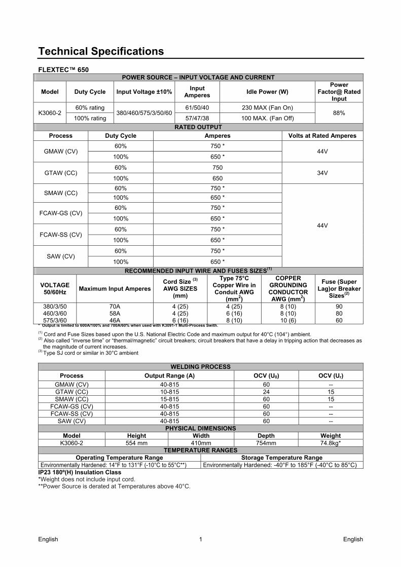
Technical Specifications FLEXTEC™ 650
POWER SOURCE – INPUT VOLTAGE AND CURRENT
Model Duty Cycle Input Voltage ±10%Input
Amperes Idle Power (W)
Power Factor@ Rated
Input
K3060-2 60% rating
380/460/575/3/50/6061/50/40 230 MAX (Fan On)
88% 100% rating 57/47/38 100 MAX. (Fan Off)
RATED OUTPUT
Process Duty Cycle Amperes Volts at Rated Amperes
GMAW (CV) 60% 750 *
44V 100% 650 *
GTAW (CC) 60% 750
34V 100% 650
SMAW (CC) 60% 750 *
44V
100% 650 *
FCAW-GS (CV) 60% 750 *
100% 650 *
FCAW-SS (CV) 60% 750 *
100% 650 *
SAW (CV) 60% 750 *
100% 650 *
RECOMMENDED INPUT WIRE AND FUSES SIZES(1)
VOLTAGE 50/60Hz
Maximum Input Amperes Cord Size (3)
AWG SIZES (mm)
Type 75°C Copper Wire in Conduit AWG
(mm2)
COPPER GROUNDING CONDUCTOR AWG (mm2)
Fuse (Super Lag)or Breaker
Sizes(2)
380/3/50 460/3/60 575/3/60
70A 58A 46A
4 (25) 4 (25) 6 (16)
4 (25) 6 (16) 8 (10)
8 (10) 8 (10) 10 (6)
90 80 60
* Output is limited to 600A/100% and 700A/60% when used with K3091-1 Multi-Process Swith.
(1) Cord and Fuse Sizes based upon the U.S. National Electric Code and maximum output for 40°C (104°) ambient. (2) Also called “inverse time” or “thermal/magnetic” circuit breakers; circuit breakers that have a delay in tripping action that decreases as
the magnitude of current increases. (3) Type SJ cord or similar in 30°C ambient
WELDING PROCESS
Process Output Range (A) OCV (U0) OCV (Ur)
GMAW (CV) 40-815 60 -- GTAW (CC) 10-815 24 15 SMAW (CC) 15-815 60 15
FCAW-GS (CV) 40-815 60 -- FCAW-SS (CV) 40-815 60 --
SAW (CV) 40-815 60 -- PHYSICAL DIMENSIONS
Model Height Width Depth WeightK3060-2 554 mm 410mm 754mm 74.8kg*
TEMPERATURE RANGESOperating Temperature Range Storage Temperature Range
Environmentally Hardened: 14°F to 131°F (-10°C to 55°C**) Environmentally Hardened: -40°F to 185°F (-40°C to 85°C) IP23 180º(H) Insulation Class *Weight does not include input cord. **Power Source is derated at Temperatures above 40°C.
English English 2
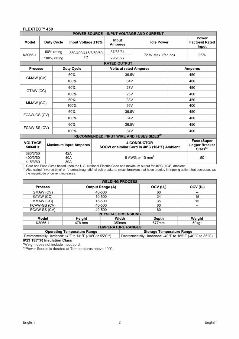
FLEXTEC™ 450
POWER SOURCE – INPUT VOLTAGE AND CURRENT
Model Duty Cycle Input Voltage ±10%Input
Amperes Idle Power
Power Factor@ Rated
Input
K3065-1 60% rating 380/400/415/3/50/60
Hz
37/35/34 72 W Max. (fan on) 95%
100% rating 29/28/27
RATED OUTPUT
Process Duty Cycle Volts at rated Amperes Amperes
GMAW (CV) 60% 36.5V 450
100% 34V 400
GTAW (CC) 60% 28V 450
100% 26V 400
MMAW (CC) 60% 38V 450
100% 36V 400
FCAW-GS (CV) 60% 36.5V 450
100% 34V 400
FCAW-SS (CV) 60% 36.5V 450
100% 34V 400
RECOMMENDED INPUT WIRE AND FUSES SIZES(1)
VOLTAGE 50/60Hz
Maximum Input Amperes 4 CONDUCTOR
SOOW or similar Cord in 40°C (104°F) Ambient
Fuse (Super Lag)or Breaker
Sizes(2) 380/3/50 400/3/60 415/3/60
42A 40A 39A
8 AWG or 10 mm2 50
(1) Cord and Fuse Sizes based upon the U.S. National Electric Code and maximum output for 40°C (104°) ambient. (2) Also called “inverse time” or “thermal/magnetic” circuit breakers; circuit breakers that have a delay in tripping action that decreases as
the magnitude of current increases.
WELDING PROCESS
Process Output Range (A) OCV (U0) OCV (Ur)
GMAW (CV) 40-500 60 -- GTAW (CC) 10-500 24 15 MMAW (CC) 15-500 35 15
FCAW-GS (CV) 40-500 60 -- FCAW-SS (CV) 40-500 60 --
PHYSICAL DIMENSIONSModel Height Width Depth Weight
K3065-1 478 mm 359mm 677mm 59kg* TEMPERATURE RANGES
Operating Temperature Range Storage Temperature Range Environmentally Hardened: 14°F to 131°F (-10°C to 55°C**) Environmentally Hardened: -40°F to 185°F (-40°C to 85°C)
IP23 155º(F) Insulation Class *Weight does not include input cord. **Power Source is derated at Temperatures above 40°C.

English English 3
Electromagnetic Compatibility (EMC) 11/04
This machine has been designed in accordance with all relevant directives and standards. However, it may still generate electromagnetic disturbances that can affect other systems like telecommunications (telephone, radio, and television) or other safety systems. These disturbances can cause safety problems in the affected systems. Read and understand this section to eliminate or reduce the amount of electromagnetic disturbance generated by this machine.
This machine has been designed to operate in an industrial area. The operator must install and operate this equipment as described in this manual. If any electromagnetic disturbances are detected the operator must put in place corrective actions to eliminate these disturbances with, if necessary, assistance from Lincoln Electric. The Class A equipment is not intended for use in residential locations where the electrical
power is provided by the public low-voltage supply system. There may be potential difficulties in ensuring electromagnetic compatibility in those locations, due to conducted as well as radiated disturbances. This equipment does not comply with IEC 61000-3-12. If it is connected to a public low-voltage system, it is responsibility of the installer or user of the equipment to ensure, by consultation with the distribution network operator if necessary, that the equipment may be connected. Before installing the machine, the operator must check the work area for any devices that may malfunction because of electromagnetic disturbances. Consider the following. Input and output cables, control cables, and telephone cables that are in or adjacent to the work area and the
machine. Radio and/or television transmitters and receivers. Computers or computer controlled equipment. Safety and control equipment for industrial processes. Equipment for calibration and measurement. Personal medical devices like pacemakers and hearing aids. Check the electromagnetic immunity for equipment operating in or near the work area. The operator must be sure
that all equipment in the area is compatible. This may require additional protection measures. The dimensions of the work area to consider will depend on the construction of the area and other activities that are
taking place. Consider the following guidelines to reduce electromagnetic emissions from the machine. Connect the machine to the input supply according to this manual. If disturbances occur if may be necessary to take
additional precautions such as filtering the input supply. The output cables should be kept as short as possible and should be positioned together. If possible connect the
work piece to ground in order to reduce the electromagnetic emissions. The operator must check that connecting the work piece to ground does not cause problems or unsafe operating conditions for personnel and equipment.
Shielding of cables in the work area can reduce electromagnetic emissions. This may be necessary for special applications.
Only for Flextec™ 650: CE input filter kit K3129-1 must be installed. Instructions how to install the CE filter kit are provided with the kit.
English English 4
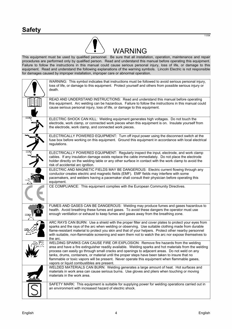
Safety 11/04
WARNING This equipment must be used by qualified personnel. Be sure that all installation, operation, maintenance and repair procedures are performed only by qualified person. Read and understand this manual before operating this equipment. Failure to follow the instructions in this manual could cause serious personal injury, loss of life, or damage to this equipment. Read and understand the following explanations of the warning symbols. Lincoln Electric is not responsible for damages caused by improper installation, improper care or abnormal operation.
WARNING: This symbol indicates that instructions must be followed to avoid serious personal injury, loss of life, or damage to this equipment. Protect yourself and others from possible serious injury or death.
READ AND UNDERSTAND INSTRUCTIONS: Read and understand this manual before operating this equipment. Arc welding can be hazardous. Failure to follow the instructions in this manual could cause serious personal injury, loss of life, or damage to this equipment.
ELECTRIC SHOCK CAN KILL: Welding equipment generates high voltages. Do not touch the electrode, work clamp, or connected work pieces when this equipment is on. Insulate yourself from the electrode, work clamp, and connected work pieces.
ELECTRICALLY POWERED EQUIPMENT: Turn off input power using the disconnect switch at the fuse box before working on this equipment. Ground this equipment in accordance with local electrical regulations.
ELECTRICALLY POWERED EQUIPMENT: Regularly inspect the input, electrode, and work clamp cables. If any insulation damage exists replace the cable immediately. Do not place the electrode holder directly on the welding table or any other surface in contact with the work clamp to avoid the risk of accidental arc ignition.
ELECTRIC AND MAGNETIC FIELDS MAY BE DANGEROUS: Electric current flowing through any conductor creates electric and magnetic fields (EMF). EMF fields may interfere with some pacemakers, and welders having a pacemaker shall consult their physician before operating this equipment.
CE COMPLIANCE: This equipment complies with the European Community Directives.
FUMES AND GASES CAN BE DANGEROUS: Welding may produce fumes and gases hazardous to health. Avoid breathing these fumes and gases. To avoid these dangers the operator must use enough ventilation or exhaust to keep fumes and gases away from the breathing zone.
ARC RAYS CAN BURN: Use a shield with the proper filter and cover plates to protect your eyes from sparks and the rays of the arc when welding or observing. Use suitable clothing made from durable flame-resistant material to protect you skin and that of your helpers. Protect other nearby personnel with suitable, non-flammable screening and warn them not to watch the arc nor expose themselves to the arc.
WELDING SPARKS CAN CAUSE FIRE OR EXPLOSION: Remove fire hazards from the welding area and have a fire extinguisher readily available. Welding sparks and hot materials from the welding process can easily go through small cracks and openings to adjacent areas. Do not weld on any tanks, drums, containers, or material until the proper steps have been taken to insure that no flammable or toxic vapors will be present. Never operate this equipment when flammable gases, vapors or liquid combustibles are present.
WELDED MATERIALS CAN BURN: Welding generates a large amount of heat. Hot surfaces and materials in work area can cause serious burns. Use gloves and pliers when touching or moving materials in the work area.
SAFETY MARK: This equipment is suitable for supplying power for welding operations carried out in an environment with increased hazard of electric shock.
English English 5
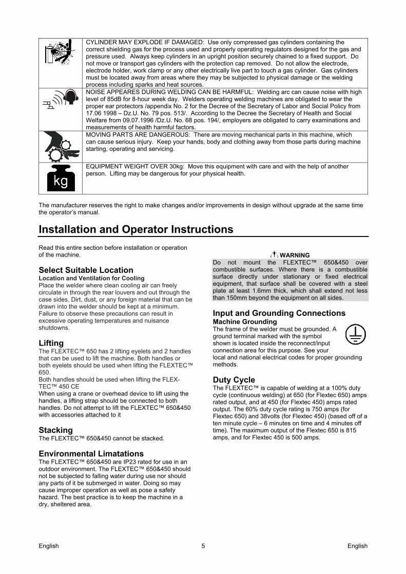
CYLINDER MAY EXPLODE IF DAMAGED: Use only compressed gas cylinders containing the correct shielding gas for the process used and properly operating regulators designed for the gas and pressure used. Always keep cylinders in an upright position securely chained to a fixed support. Do not move or transport gas cylinders with the protection cap removed. Do not allow the electrode, electrode holder, work clamp or any other electrically live part to touch a gas cylinder. Gas cylinders must be located away from areas where they may be subjected to physical damage or the welding process including sparks and heat sources.
NOISE APPEARES DURING WELDING CAN BE HARMFUL: Welding arc can cause noise with high level of 85dB for 8-hour week day. Welders operating welding machines are obligated to wear the proper ear protectors /appendix No. 2 for the Decree of the Secretary of Labor and Social Policy from 17.06 1998 – Dz.U. No. 79 pos. 513/. According to the Decree the Secretary of Health and Social Welfare from 09.07.1996 /Dz.U. No. 68 pos. 194/, employers are obligated to carry examinations and measurements of health harmful factors. MOVING PARTS ARE DANGEROUS: There are moving mechanical parts in this machine, which can cause serious injury. Keep your hands, body and clothing away from those parts during machine starting, operating and servicing.
EQUIPMENT WEIGHT OVER 30kg: Move this equipment with care and with the help of another person. Lifting may be dangerous for your physical health.
The manufacturer reserves the right to make changes and/or improvements in design without upgrade at the same time the operator’s manual.
Installation and Operator Instructions Read this entire section before installation or operation of the machine.
Select Suitable Location Location and Ventilation for Cooling Place the welder where clean cooling air can freely circulate in through the rear louvers and out through the case sides. Dirt, dust, or any foreign material that can be drawn into the welder should be kept at a minimum. Failure to observe these precautions can result in excessive operating temperatures and nuisance shutdowns.
Lifting The FLEXTEC™ 650 has 2 lifting eyelets and 2 handles that can be used to lift the machine. Both handles or both eyelets should be used when lifting the FLEXTEC™ 650. Both handles should be used when lifting the FLEX-TEC™ 450 CE When using a crane or overhead device to lift using the handles, a lifting strap should be connected to both handles. Do not attempt to lift the FLEXTEC™ 650&450 with accessories attached to it
Stacking The FLEXTEC™ 650&450 cannot be stacked.
Environmental Limatations The FLEXTEC™ 650&450 are IP23 rated for use in an outdoor environment. The FLEXTEC™ 650&450 should not be subjected to falling water during use nor should any parts of it be submerged in water. Doing so may cause improper operation as well as pose a safety hazard. The best practice is to keep the machine in a dry, sheltered area.
WARNING
Do not mount the FLEXTEC™ 650&450 over combustible surfaces. Where there is a combustible surface directly under stationary or fixed electrical equipment, that surface shall be covered with a steel plate at least 1.6mm thick, which shall extend not less than 150mm beyond the equipment on all sides.
Input and Grounding Connections Machine Grounding The frame of the welder must be grounded. A ground terminal marked with the symbol shown is located inside the reconnect/input connection area for this purpose. See your local and national electrical codes for proper grounding methods.
Duty Cycle The FLEXTEC™ is capable of welding at a 100% duty cycle (continuous welding) at 650 (for Flextec 650) amps rated output, and at 450 (for Flextec 450) amps rated output. The 60% duty cycle rating is 750 amps (for Flextec 650) and 38volts (for Flextec 450) (based off of a ten minute cycle – 6 minutes on time and 4 minutes off time). The maximum output of the Flextec 650 is 815 amps, and for Flextec 450 is 500 amps.
English English 6
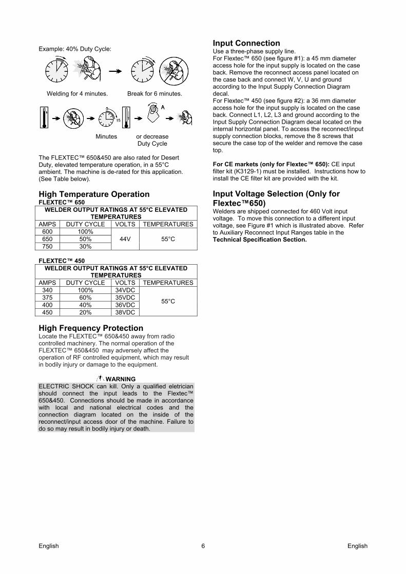
Example: 40% Duty Cycle:
Welding for 4 minutes. Break for 6 minutes.
Minutes or decrease
Duty Cycle
The FLEXTEC™ 650&450 are also rated for Desert Duty, elevated temperature operation, in a 55°C ambient. The machine is de-rated for this application. (See Table below).
High Temperature Operation FLEXTEC™ 650
WELDER OUTPUT RATINGS AT 55°C ELEVATED TEMPERATURES
AMPS DUTY CYCLE VOLTS TEMPERATURES 600 100%
44V 55°C 650 50% 750 30%
FLEXTEC™ 450
WELDER OUTPUT RATINGS AT 55°C ELEVATED TEMPERATURES
AMPS DUTY CYCLE VOLTS TEMPERATURES 340 100% 34VDC
55°C 375 60% 35VDC 400 40% 36VDC 450 20% 38VDC
High Frequency Protection Locate the FLEXTEC™ 650&450 away from radio controlled machinery. The normal operation of the FLEXTEC™ 650&450 may adversely affect the operation of RF controlled equipment, which may result in bodily injury or damage to the equipment.
WARNING ELECTRIC SHOCK can kill. Only a qualified eletrician should connect the input leads to the Flextec™ 650&450. Connections should be made in accordance with local and national electrical codes and the connection diagram located on the inside of the reconnect/input access door of the machine. Failure to do so may result in bodily injury or death.
Input Connection Use a three-phase supply line. For Flextec™ 650 (see figure #1): a 45 mm diameter access hole for the input supply is located on the case back. Remove the reconnect access panel located on the case back and connect W, V, U and ground according to the Input Supply Connection Diagram decal. For Flextec™ 450 (see figure #2): a 36 mm diameter access hole for the input supply is located on the case back. Connect L1, L2, L3 and ground according to the Input Supply Connection Diagram decal located on the internal horizontal panel. To access the reconnect/input supply connection blocks, remove the 8 screws that secure the case top of the welder and remove the case top. For CE markets (only for Flextec™ 650): CE input filter kit (K3129-1) must be installed. Instructions how to install the CE filter kit are provided with the kit.
Input Voltage Selection (Only for Flextec™650) Welders are shipped connected for 460 Volt input voltage. To move this connection to a different input voltage, see Figure #1 which is illustrated above. Refer to Auxiliary Reconnect Input Ranges table in the Technical Specification Section.
English English 7
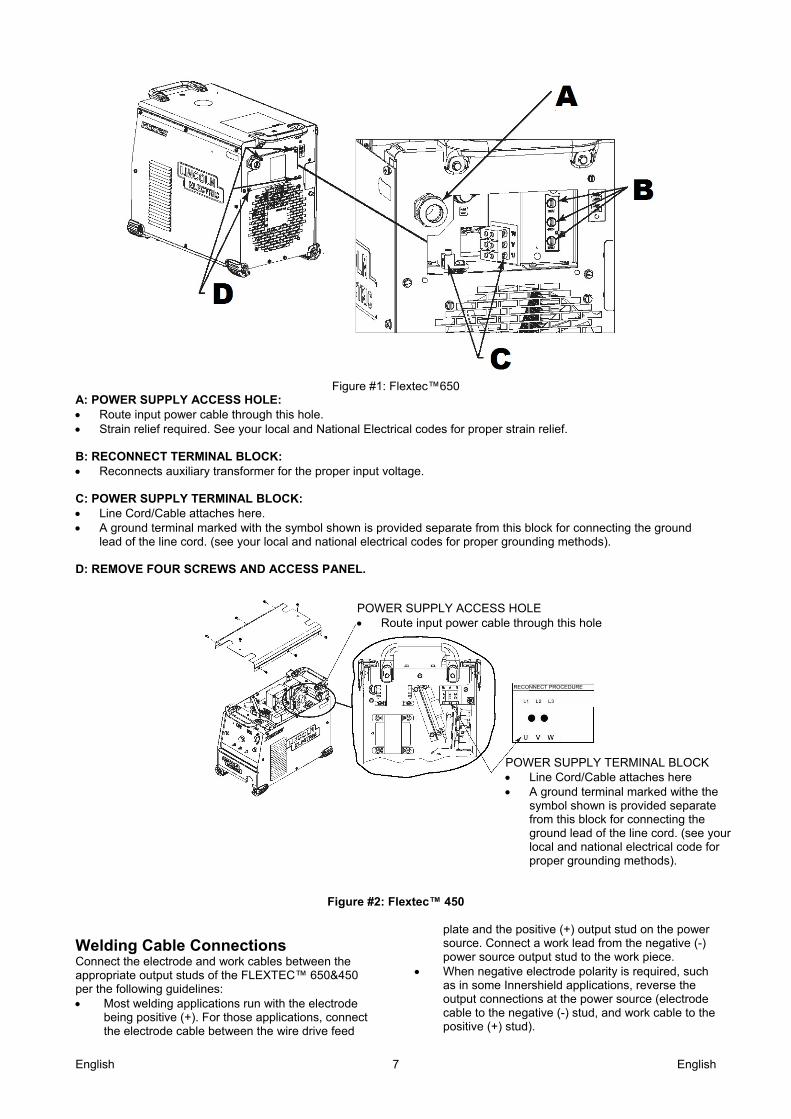
Figure #1: Flextec™650
A: POWER SUPPLY ACCESS HOLE: Route input power cable through this hole. Strain relief required. See your local and National Electrical codes for proper strain relief.
B: RECONNECT TERMINAL BLOCK: Reconnects auxiliary transformer for the proper input voltage.
C: POWER SUPPLY TERMINAL BLOCK: Line Cord/Cable attaches here. A ground terminal marked with the symbol shown is provided separate from this block for connecting the ground
lead of the line cord. (see your local and national electrical codes for proper grounding methods).
D: REMOVE FOUR SCREWS AND ACCESS PANEL.
Figure #2: Flextec™ 450
Welding Cable Connections Connect the electrode and work cables between the appropriate output studs of the FLEXTEC™ 650&450 per the following guidelines: Most welding applications run with the electrode
being positive (+). For those applications, connect the electrode cable between the wire drive feed
plate and the positive (+) output stud on the power source. Connect a work lead from the negative (-) power source output stud to the work piece.
When negative electrode polarity is required, such as in some Innershield applications, reverse the output connections at the power source (electrode cable to the negative (-) stud, and work cable to the positive (+) stud).
POWER SUPPLY ACCESS HOLE Route input power cable through this hole
RECONNECT PROCEDURE
POWER SUPPLY TERMINAL BLOCK Line Cord/Cable attaches here A ground terminal marked withe the
symbol shown is provided separate from this block for connecting the ground lead of the line cord. (see your local and national electrical code for proper grounding methods).
English English 8
Control Cable Connections General guidelines Genuine Lincoln control cables should be used at all times (except where noted otherwise). Generally, it is recommended that the total length not exceed 100 feet (30.5 m). The use of non-standard cables, especially in lengths greater than 25 feet, can lead to communication problems (system shutdowns), poor motor acceleration (poor arc starting), and low wire driving force (wire feeding problems). Always use the shortest length of control cable possible, and DO NOT coil excess cable. Regarding cable placement, best results will be obtained when control cables are routed separate from the weld cables. This minimizes the possibility of interference between the high currents flowing through the weld cables, and the low level signals in the control cables.
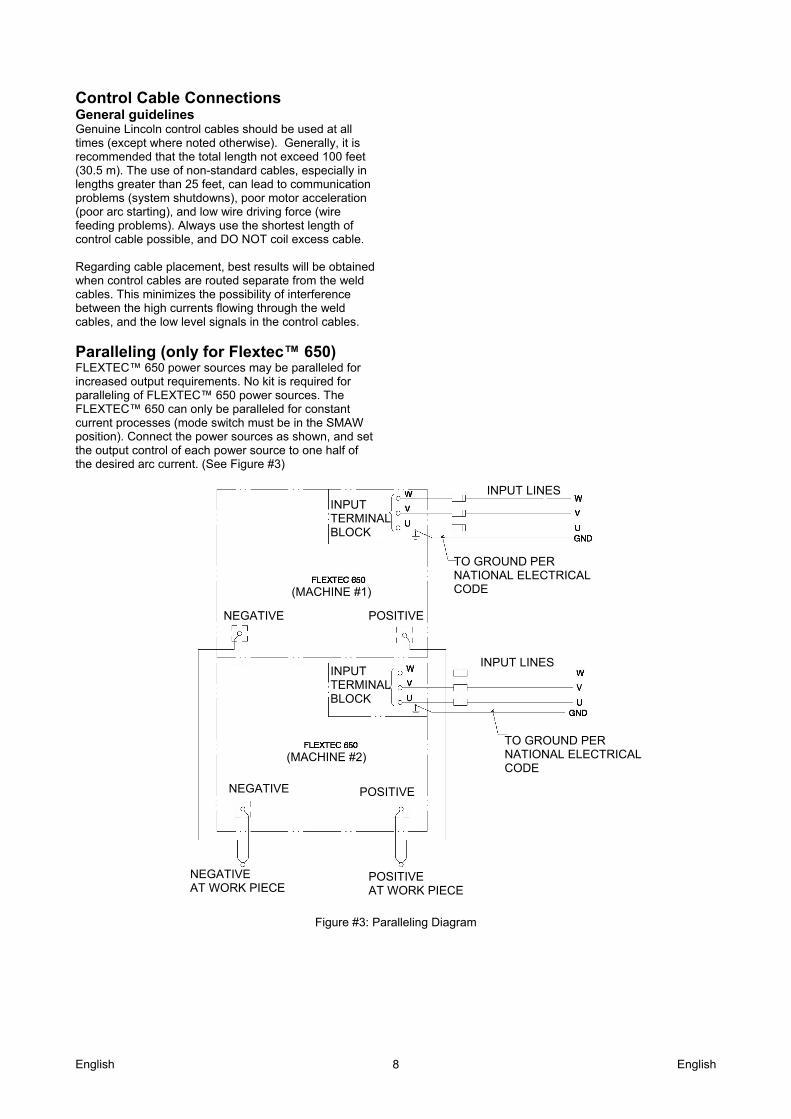
Paralleling (only for Flextec™ 650) FLEXTEC™ 650 power sources may be paralleled for increased output requirements. No kit is required for paralleling of FLEXTEC™ 650 power sources. The FLEXTEC™ 650 can only be paralleled for constant current processes (mode switch must be in the SMAW position). Connect the power sources as shown, and set the output control of each power source to one half of the desired arc current. (See Figure #3)
Figure #3: Paralleling Diagram
INPUT TERMINAL BLOCK
INPUT TERMINAL BLOCK
(MACHINE #1)
(MACHINE #2)
NEGATIVE POSITIVE
NEGATIVE AT WORK PIECE
POSITIVE AT WORK PIECE
NEGATIVE POSITIVE
INPUT LINES
INPUT LINES
TO GROUND PER NATIONAL ELECTRICAL CODE
TO GROUND PER NATIONAL ELECTRICAL CODE
English English 9
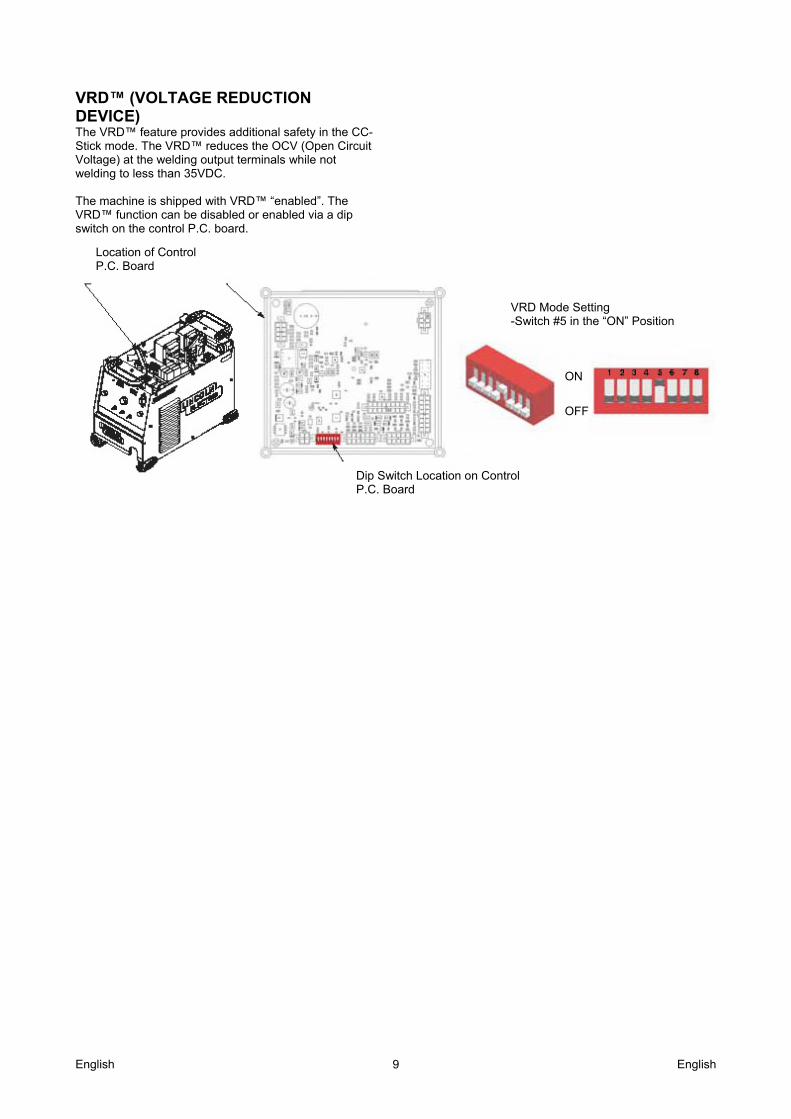
VRD™ (VOLTAGE REDUCTION DEVICE) The VRD™ feature provides additional safety in the CC-Stick mode. The VRD™ reduces the OCV (Open Circuit Voltage) at the welding output terminals while not welding to less than 35VDC. The machine is shipped with VRD™ “enabled”. The VRD™ function can be disabled or enabled via a dip switch on the control P.C. board.
Location of Control P.C. Board
Dip Switch Location on Control P.C. Board
VRD Mode Setting -Switch #5 in the “ON” Position
ON
OFF
English English 10
Product Description The FLEXTEC™ 650 is a multi-process CC/CV DC inverter and is rated for 650 amps, 44 volts at a 100% duty cycle. The FLEXTEC™ 450 is a multi-process CC/CV DC inverter and is rated for 450 amps, 38 volts at a 60% duty cycle. The FLEXTEC™ 650&450 are intended for both factory and field operation. It comes in a compact, rugged case that is designed for portability and outdoor use with an IP23 environmental rating. The FLEXTEC™ 650 operates on 3 phase 380V, 460V, or 575V 50hz or 60hz power. The FLEXTEC™ 450 CE operates on 380V, 400V, or 415V 50hz or 60hz power. The FLEXTEC™ 650&450 are designed for CC-SMAW, CC-GTAW (lift tig), CV-GMAW, CV-FCAW-SS, CV-FCAW-GS and CV-SAW (only for Flextec™ 650) welding processes. CAG (arc gouging) is also supported
Design Features Severe Duty Design for outdoor use (IP23 rating) Passive Power Factor Correction – reliably gives
88% (for Flextec™ 650) and 95% (for Flextec™ 450) power factor for lower installation costs.
91% (for Flextec™ 650) and 89% (for Flextec™ 450) Efficiency rating – reduces electrical utility costs.
F.A.N. (fan as needed). Cooling fan runs when the output is energized and for a 5 minute cool down period after output is disabled.
Thermal protection by thermostats with Thermal Indicator LED.
Error Codes display on LED screen for ease of trouble shooting.
Electronic over current protection. Input voltage misconnection protection. Utilizes digital signal processing and microprocessor
control. VRD™ Voltage Reduction Device - Enable this
function for reduced OCV in CC modes for added safety.
Capabilities The following capabilities are supported: Wire Feeders: LF33, LN10, DH10, LN25-Pro, LT-7Tractor and NA series (only for Flextec™ 650).
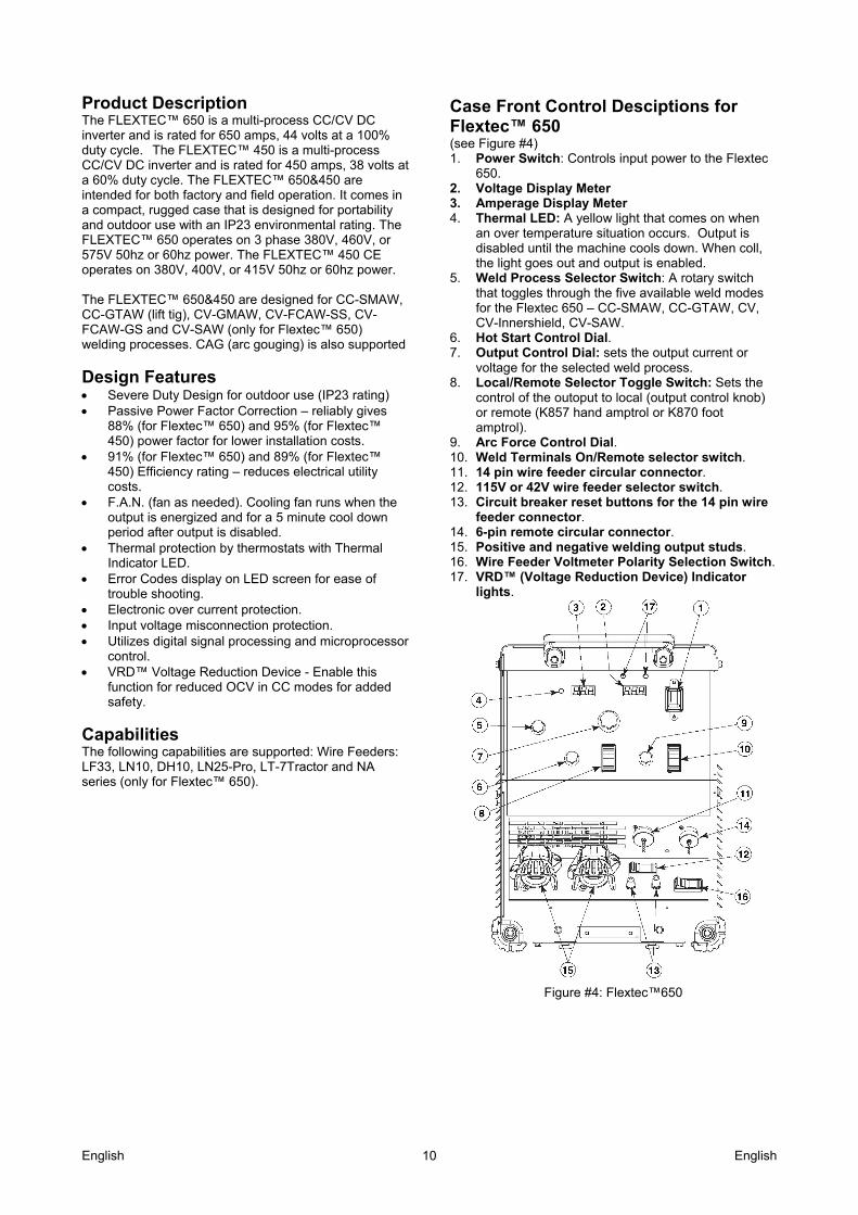
Case Front Control Desciptions for Flextec™ 650 (see Figure #4) 1. Power Switch: Controls input power to the Flextec
650. 2. Voltage Display Meter 3. Amperage Display Meter 4. Thermal LED: A yellow light that comes on when
an over temperature situation occurs. Output is disabled until the machine cools down. When coll, the light goes out and output is enabled.
5. Weld Process Selector Switch: A rotary switch that toggles through the five available weld modes for the Flextec 650 – CC-SMAW, CC-GTAW, CV, CV-Innershield, CV-SAW.
6. Hot Start Control Dial. 7. Output Control Dial: sets the output current or
voltage for the selected weld process. 8. Local/Remote Selector Toggle Switch: Sets the
control of the outoput to local (output control knob) or remote (K857 hand amptrol or K870 foot amptrol).
9. Arc Force Control Dial. 10. Weld Terminals On/Remote selector switch. 11. 14 pin wire feeder circular connector. 12. 115V or 42V wire feeder selector switch. 13. Circuit breaker reset buttons for the 14 pin wire
feeder connector. 14. 6-pin remote circular connector. 15. Positive and negative welding output studs. 16. Wire Feeder Voltmeter Polarity Selection Switch. 17. VRD™ (Voltage Reduction Device) Indicator
lights.
Figure #4: Flextec™650
English English 11
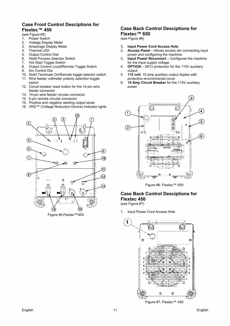
Case Front Control Desciptions for Flextec™ 450 (see Figure #5) 1. Power Switch 2. Voltage Display Meter 3. Amperage Display Meter 4. Thermal LED 5. Output Control Dial 6. Weld Process Selector Switch 7. Hot Start Toggle Switch 8. Output Control Local/Remote Toggle Switch 9. Arc Control Dia 10. Weld Terminals On/Remote toggle selector switch 11. Wire feeder voltmeter polarity selection toggle
switch 12. Circuit breaker reset button for the 14-pin wire
feeder connector 13. 14-pin wire feeder circular connector 14. 6-pin remote circular connector 15. Positive and negative welding output studs 16. VRD™ (Voltage Reduction Device) Indicator lights
Figure #5:Flextec™450
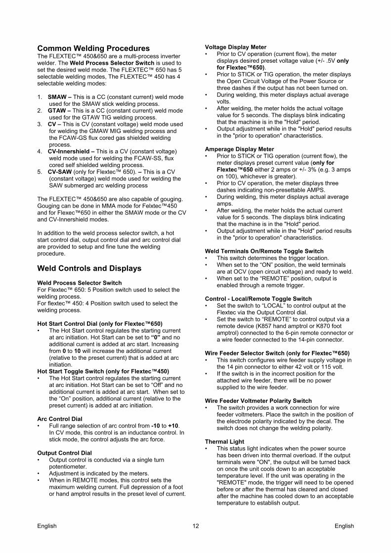
Case Back Control Desciptions for Flextec™ 650 (see Figure #6) 1. Input Power Cord Access Hole 2. Access Panel – Allows access dor connecting input
power and configuring the machine. 3. Input Power Reconnect – Configures the machine
for the input supply voltage. 4. OPTION – GFCI protection for the 115V auxiliary
output. 5. 115 volt, 15 amp auxiliary output duplex with
protective environmental cover. 6. 15 Amp Circuit Breaker for the 115V auxiliary
power.
Figure #6: Flextec™ 650
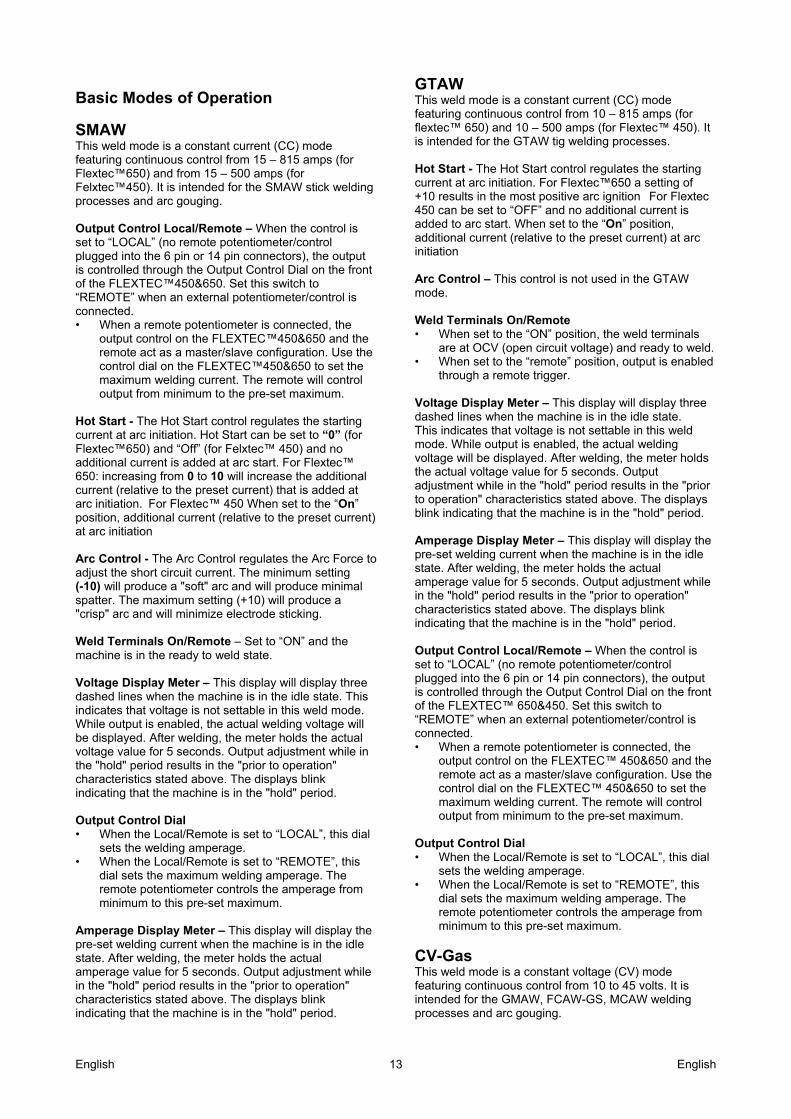
Case Back Control Desciptions for Flextec 450 (see Figure #7) 1. Input Power Cord Access Hole
Figure #7: Flextec™ 450
English English 12
Common Welding Procedures The FLEXTEC™ 450&650 are a multi-process inverter welder. The Weld Process Selector Switch is used to set the desired weld mode. The FLEXTEC™ 650 has 5 selectable welding modes, The FLEXTEC™ 450 has 4 selectable welding modes: 1. SMAW – This is a CC (constant current) weld mode
used for the SMAW stick welding process. 2. GTAW – This is a CC (constant current) weld mode
used for the GTAW TIG welding process. 3. CV – This is CV (constant voltage) weld mode used
for welding the GMAW MIG welding process and the FCAW-GS flux cored gas shielded welding process.
4. CV-Innershield – This is a CV (constant voltage) weld mode used for welding the FCAW-SS, flux cored self shielded welding process.
5. CV-SAW (only for Flextec™ 650). – This is a CV (constant voltage) weld mode used for welding the SAW submerged arc welding process
The FLEXTEC™ 450&650 are also capable of gouging. Gouging can be done in MMA mode for Felxtec™450 and for Flexec™650 in either the SMAW mode or the CV and CV-Innershield modes. In addition to the weld process selector switch, a hot start control dial, output control dial and arc control dial are provided to setup and fine tune the welding procedure.
Weld Controls and Displays Weld Process Selector Switch For Flextec™ 650: 5 Position switch used to select the welding process. For flextec™ 450: 4 Position switch used to select the welding process. Hot Start Control Dial (only for Flextec™650) • The Hot Start control regulates the starting current
at arc initiation. Hot Start can be set to “0” and no additional current is added at arc start. Increasing from 0 to 10 will increase the additional current (relative to the preset current) that is added at arc initiation.
Hot Start Toggle Switch (only for Flextec™450) • The Hot Start control regulates the starting current
at arc initiation. Hot Start can be set to “Off” and no additional current is added at arc start. When set to the “On” position, additional current (relative to the preset current) is added at arc initiation.
Arc Control Dial • Full range selection of arc control from -10 to +10.
In CV mode, this control is an inductance control. In stick mode, the control adjusts the arc force.
Output Control Dial • Output control is conducted via a single turn
potentiometer. • Adjustment is indicated by the meters. • When in REMOTE modes, this control sets the
maximum welding current. Full depression of a foot or hand amptrol results in the preset level of current.
Voltage Display Meter • Prior to CV operation (current flow), the meter
displays desired preset voltage value (+/- .5V only for Flextec™650).
• Prior to STICK or TIG operation, the meter displays the Open Circuit Voltage of the Power Source or three dashes if the output has not been turned on.
• During welding, this meter displays actual average volts.
• After welding, the meter holds the actual voltage value for 5 seconds. The displays blink indicating that the machine is in the "Hold" period.
• Output adjustment while in the "Hold" period results in the "prior to operation" characteristics.
Amperage Display Meter • Prior to STICK or TIG operation (current flow), the
meter displays preset current value (only for Flextec™650 either 2 amps or +/- 3% (e.g. 3 amps on 100), whichever is greater).
• Prior to CV operation, the meter displays three dashes indicating non-presettable AMPS.
• During welding, this meter displays actual average amps.
• After welding, the meter holds the actual current value for 5 seconds. The displays blink indicating that the machine is in the "Hold" period.
• Output adjustment while in the "Hold" period results in the "prior to operation" characteristics.
Weld Terminals On/Remote Toggle Switch • This switch determines the trigger location. • When set to the “ON” position, the weld terminals
are at OCV (open circuit voltage) and ready to weld. • When set to the “REMOTE” position, output is
enabled through a remote trigger.
Control - Local/Remote Toggle Switch • Set the switch to “LOCAL” to control output at the
Flextec via the Output Control dial. • Set the switch to “REMOTE” to control output via a
remote device (K857 hand amptrol or K870 foot amptrol) connected to the 6-pin remote connector or a wire feeder connected to the 14-pin connector.
Wire Feeder Selector Switch (only for Flextec™650) • This switch configures wire feeder supply voltage in
the 14 pin connector to either 42 volt or 115 volt. • If the switch is in the incorrect position for the
attached wire feeder, there will be no power supplied to the wire feeder.
Wire Feeder Voltmeter Polarity Switch • The switch provides a work connection for wire
feeder voltmeters. Place the switch in the position of the electrode polarity indicated by the decal. The switch does not change the welding polarity.
Thermal Light • This status light indicates when the power source
has been driven into thermal overload. If the output terminals were "ON", the output will be turned back on once the unit cools down to an acceptable temperature level. If the unit was operating in the "REMOTE" mode, the trigger will need to be opened before or after the thermal has cleared and closed after the machine has cooled down to an acceptable temperature to establish output.
English English 13
Basic Modes of Operation
SMAW This weld mode is a constant current (CC) mode featuring continuous control from 15 – 815 amps (for Flextec™650) and from 15 – 500 amps (for Felxtec™450). It is intended for the SMAW stick welding processes and arc gouging. Output Control Local/Remote – When the control is set to “LOCAL” (no remote potentiometer/control plugged into the 6 pin or 14 pin connectors), the output is controlled through the Output Control Dial on the front of the FLEXTEC™450&650. Set this switch to “REMOTE” when an external potentiometer/control is connected. • When a remote potentiometer is connected, the
output control on the FLEXTEC™450&650 and the remote act as a master/slave configuration. Use the control dial on the FLEXTEC™450&650 to set the maximum welding current. The remote will control output from minimum to the pre-set maximum.
Hot Start - The Hot Start control regulates the starting current at arc initiation. Hot Start can be set to “0” (for Flextec™650) and “Off” (for Felxtec™ 450) and no additional current is added at arc start. For Flextec™ 650: increasing from 0 to 10 will increase the additional current (relative to the preset current) that is added at arc initiation. For Flextec™ 450 When set to the “On” position, additional current (relative to the preset current) at arc initiation Arc Control - The Arc Control regulates the Arc Force to adjust the short circuit current. The minimum setting (-10) will produce a "soft" arc and will produce minimal spatter. The maximum setting (+10) will produce a "crisp" arc and will minimize electrode sticking. Weld Terminals On/Remote – Set to “ON” and the machine is in the ready to weld state. Voltage Display Meter – This display will display three dashed lines when the machine is in the idle state. This indicates that voltage is not settable in this weld mode. While output is enabled, the actual welding voltage will be displayed. After welding, the meter holds the actual voltage value for 5 seconds. Output adjustment while in the "hold" period results in the "prior to operation" characteristics stated above. The displays blink indicating that the machine is in the "hold" period. Output Control Dial • When the Local/Remote is set to “LOCAL”, this dial
sets the welding amperage. • When the Local/Remote is set to “REMOTE”, this
dial sets the maximum welding amperage. The remote potentiometer controls the amperage from minimum to this pre-set maximum.
Amperage Display Meter – This display will display the pre-set welding current when the machine is in the idle state. After welding, the meter holds the actual amperage value for 5 seconds. Output adjustment while in the "hold" period results in the "prior to operation" characteristics stated above. The displays blink indicating that the machine is in the "hold" period.
GTAW This weld mode is a constant current (CC) mode featuring continuous control from 10 – 815 amps (for flextec™ 650) and 10 – 500 amps (for Flextec™ 450). It is intended for the GTAW tig welding processes. Hot Start - The Hot Start control regulates the starting current at arc initiation. For Flextec™650 a setting of +10 results in the most positive arc ignition For Flextec 450 can be set to “OFF” and no additional current is added to arc start. When set to the “On” position, additional current (relative to the preset current) at arc initiation Arc Control – This control is not used in the GTAW mode. Weld Terminals On/Remote • When set to the “ON” position, the weld terminals
are at OCV (open circuit voltage) and ready to weld. • When set to the “remote” position, output is enabled
through a remote trigger.
Voltage Display Meter – This display will display three dashed lines when the machine is in the idle state. This indicates that voltage is not settable in this weld mode. While output is enabled, the actual welding voltage will be displayed. After welding, the meter holds the actual voltage value for 5 seconds. Output adjustment while in the "hold" period results in the "prior to operation" characteristics stated above. The displays blink indicating that the machine is in the "hold" period. Amperage Display Meter – This display will display the pre-set welding current when the machine is in the idle state. After welding, the meter holds the actual amperage value for 5 seconds. Output adjustment while in the "hold" period results in the "prior to operation" characteristics stated above. The displays blink indicating that the machine is in the "hold" period. Output Control Local/Remote – When the control is set to “LOCAL” (no remote potentiometer/control plugged into the 6 pin or 14 pin connectors), the output is controlled through the Output Control Dial on the front of the FLEXTEC™ 650&450. Set this switch to “REMOTE” when an external potentiometer/control is connected. • When a remote potentiometer is connected, the
output control on the FLEXTEC™ 450&650 and the remote act as a master/slave configuration. Use the control dial on the FLEXTEC™ 450&650 to set the maximum welding current. The remote will control output from minimum to the pre-set maximum.
Output Control Dial • When the Local/Remote is set to “LOCAL”, this dial
sets the welding amperage. • When the Local/Remote is set to “REMOTE”, this
dial sets the maximum welding amperage. The remote potentiometer controls the amperage from minimum to this pre-set maximum.
CV-Gas This weld mode is a constant voltage (CV) mode featuring continuous control from 10 to 45 volts. It is intended for the GMAW, FCAW-GS, MCAW welding processes and arc gouging.
English English 14
Hot Start For Flextec™ 650– Rotate from the “0” position to the “10” position to provide more energy during the start of a weld. Hot Start For Flextec™ 450– Toggle to “ON” position to provide more energy during the start of a weld. Arc Control – The Arc Control regulates pinch effect. At the minimum setting (-10), minimizes pinch and results in a soft arc. Low pinch settings are preferable for welding with gas mixes containing mostly inert gases. At the maximum setting (+10), maximizes pinch effect and results in a crisp arc. High pinch settings are preferable for welding FCAW and GMAW with CO2. Weld Terminals On/Remote • When set to the “ON” position, the weld terminals
are at OCV (open circuit voltage) and ready to weld. This selection is used for across the arc wire feeders.
• When set to the “REMOTE” position, output is enabled through a remote trigger.
Amperage Display Meter – This display will display three dashed lines when the machine is in the idle state. This indicates that amperage is not settable in this weld mode. While output is enabled, the actual welding amperage will be displayed. After welding, the meter holds the actual amperage value for 5 seconds. Output adjustment while in the "hold" period results in the "prior to operation" characteristics stated above. The displays blink indicating that the machine is in the "hold" period. Voltage Display Meter – This display will display the pre-set welding voltage when the machine is in the idle state. After welding, the meter holds the actual voltage value for 5 seconds. Output adjustment while in the "hold" period results in the "prior to operation" characteristics stated above. The displays blink indicating that the machine is in the "hold" period. Output Control Local/Remote – When the control is set to “LOCAL” (no remote potentiometer/control plugged into the 6 pin or 14 pin connectors), the output is controlled through the Output Control Dial on the front of the FLEXTEC™ 650&450. Set this switch to “REMOTE” when an external potentiometer/control is connected. Output Control Dial When the Local/Remote is set to “LOCAL”, this dial
sets the welding voltage. When the Local/Remote is set to “REMOTE”, this
dial is disabled.
CV-Innershield This weld mode is a constant voltage (CV) mode featuring continuous control from 10 to 45 volts. It is intended for the FCAW-SS welding process and arc gouging. Hot Start For Flextec™ 650– Rotate from the “0” position to the “10” position to provide more energy during the start of a weld. Hot Start For Flextec™ 450– Toggle to “ON” position to provide more energy during the start of a weld.
Arc Control – The Arc Control regulates pinch effect. At the minimum setting (-10), minimizes pinch and results in a soft arc. At the maximum setting (+10), maximizes pinch effect and results in a crisp arc. Weld Terminals On/Remote When set to the “ON” position, the weld terminals
are at OCV (open circuit voltage) and ready to weld. This selection is used for across the arc wire feeders.
When set to the “REMOTE” position, output is enabled through a remote trigger.
Amperage Display Meter – This display will display three dashed lines when the machine is in the idle state. This indi-cates that amperage is not settable in this weld mode. While output is enabled, the actual welding amperage will be displayed. After welding, the meter holds the actual amperage value for 5 seconds. Output adjustment while in the "hold" period results in the "prior to operation" characteristics stated above. The displays blink indicating that the machine is in the "hold" period. Voltage Display Meter – This display will display the pre-set welding voltage when the machine is in the idle state. After welding, the meter holds the actual voltage value for 5 seconds. Output adjustment while in the "hold" period results in the "prior to operation" characteristics stated above. The displays blink indicating that the machine is in the "hold" period. Output Control Local/Remote – When the control is set to “LOCAL” (no remote potentiometer/control plugged into the 6 pin or 14 pin connectors), the output is controlled through the Output Control Dial on the front of the FLEXTEC™ 450&650. Set this switch to “REMOTE” when an external potentiometer/control is connected. Output Control Dial When the Local/Remote is set to “LOCAL”, this dial
sets the welding voltage. When the Local/Remote is set to “REMOTE”, this
dial is disabled.
CV-SAW (only for Flextec™650) This weld mode is a constant voltage (CV) mode featuring continuous control from 10 to 45 volts. It is intended for the CV-SAW submerged arc welding process. Hot Start – Not used for this welding process. Arc Control – Not used for this welding process . Weld Terminals On/Remote When set to the “ON” position, the weld terminals
are at OCV (open circuit voltage) and ready to weld. This selection is used for across the arc wire feeders.
When set to the “REMOTE” position, output is enabled through a remote trigger.
English English 15
Amperage Display Meter – This display will display three dashed lines when the machine is in the idle state. This indicates that amperage is not settable in this weld mode. While output is enabled, the actual welding amperage will be displayed. After welding, the meter holds the actual amperage value for 5 seconds. Output adjustment while in the "hold" period results in the "prior to operation" characteristics stated above. The displays blink indicating that the machine is in the "hold" period. Voltage Display Meter – This display will display the pre-set welding voltage when the machine is in the idle state. After welding, the meter holds the actual voltage value for 5 seconds. Output adjustment while in the "hold" period results in the "prior to operation" characteristics stated above. The displays blink indicating that the machine is in the "hold" period. Output Control Local/Remote – When the control is set to “LOCAL” (no remote potentiometer/control plugged into the 6 pin or 14 pin connectors), the output is controlled through the Output Control Dial on the front of the FLEXTEC™ 650. Set this switch to “REMOTE” when an external potentiometer/control is connected. Output Control Dial When the Local/Remote is set to “LOCAL”, this dial
sets the welding voltage. When the Local/Remote is set to “REMOTE”, this
dial is disabled
Maintenance
WARNING For any maintenance or repair operations it is recommended to contact the nearest technical service center or Lincoln Electric. Maintenance or repairs performed by unauthorized service centers or personnel will null and void the manufacturer’s warranty. The frequency of the maintenance operations may vary in accordance with the working environment. Any noticeable damage should be reported immediately. Check cables and connections integrity. Replace, if
necessary. Keep clean the machine. Use a soft dry cloth to
clean the external case, especially the airflow inlet / outlet louvers.
WARNING
Do not open this machine and do not introduce anything into its openings. Power supply must be disconnected from the machine before each maintenance and service. After each repair, perform proper tests to ensure safety.
English English 16
WEEE 07/06
En
gli
sh
Do not dispose of electrical equipment together with normal waste! In observance of European Directive 2002/96/EC on Waste Electrical and Electronic Equipment (WEEE) and its implementation in accordance with national law, electrical equipment that has reached the end of its life must be collected separately and returned to an environmentally compatible recycling facility. As the owner of the equipment, you should get information on approved collection systems from our local representative. By applying this European Directive you will protect the environment and human health!
Spare Parts 12/05
Part List reading instructions Do not use this part list for a machine if its code number is not listed. Contact the Lincoln Electric Service
Department for any code number not listed. Use the illustration of assembly page and the table below to determine where the part is located for your particular
code machine. Use only the parts marked "X" in the column under the heading number called for in the assembly page (# indicate
a change in this printing). First, read the Part List reading instructions above, then refer to the "Spare Part" manual supplied with the machine, that contains a picture-descriptive part number cross-reference.
Electrical Schematic Refer to the "Spare Part" manual supplied with the machine.
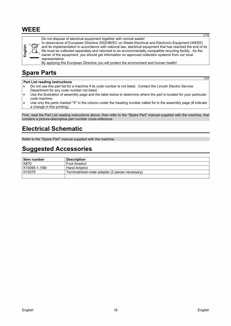
Suggested Accessories Item number Description K870 Foot Amptrol K10095-1-15M Hand Amptrol K10376 Terminal/twist-mate adapter (2 pieces necessary)


