Review of Advanced Materials for Proton Exchange Membrane FuelCellsAlexander Kraytsberg† and Yair Ein-Eli*,†,‡
†Department of Materials Science and Engineering, and ‡The Nancy and Stephan Grand Technion Energy Program (GTEP),TechnionIsrael Institute of Technology, Haifa 3200003, Israel
ABSTRACT: The scientific community is focused on the development of inexpensive and high-performing membrane materialsfor proton exchange membrane (PEM) fuel cells (FCs). The major approach to reducing the cost of FCs, which is crucial for thewidespread acceptance of FCs as energy sources for various practical applications, is reducing the cost of the membrane. Effortsare being made in the development of advanced polymeric materials, which will satisfy the technical and economic demands ofthe consumers. Because most alternative membranes are outperformed by Nafion membranes over an entire set of importantproperties, it may be worthwhile to compromise on certain parameters to develop alternative specialized membranes. This reviewpresents the properties (mainly conductivity and chemical and mechanical stability) of modern solid polymer electrolytes (SPEs)for PEM FCs.
1. INTRODUCTIONFuel cells (FCs) are electrochemical devices that produceelectrical energy from the chemical energy of a fuel and oxygen.Although the most common fuel is hydrogen, other fuels, suchas methanol, are also used. For the past 5 decades, FCs havebeen recognized as a preferred energy source for a wide varietyof applications. Hydrogen contains more energy per unit weightthan any other fuel, and therefore, a hydrogen-based powerplant may be more efficient on a weight basis than aconventional power plant that uses other fuels; this aspect isparticularly important for air, ground, and marine trans-portation. Moreover, the advantage of direct electricitygeneration from hydrogen via a FC is evident if electricalenergy is used directly (e.g., in domestic power supplies,communication equipment, electronic devices, and portableelectronics) rather than indirectly to generate mechanicalmovement. Since the 1960s, FCs have been used to powernumerous mechanical and electronic systems, from spacecraftsystems to electric vehicles, submarines, and portableelectronics.In a FC, hydrogen (or another fuel) is supplied to the anode
side, whereas oxygen (pure oxygen or air) is supplied to thecathode side. At the anode, electrons are stripped fromhydrogen atoms; the process is facilitated by a catalyst [e.g.,platinum (Pt)-containing compounds]. The produced protonspass through a proton-conducting electrolyte, whereas theelectrons are directed through an external path, powering anattached device and leading to the cathode, reducing oxygen. Atthe cathode, the protons are combined with oxygen, formingwater. Overall, the FC combines hydrogen and oxygen toproduce water and electricity.The first FC was developed as early as 1839 by Sir William
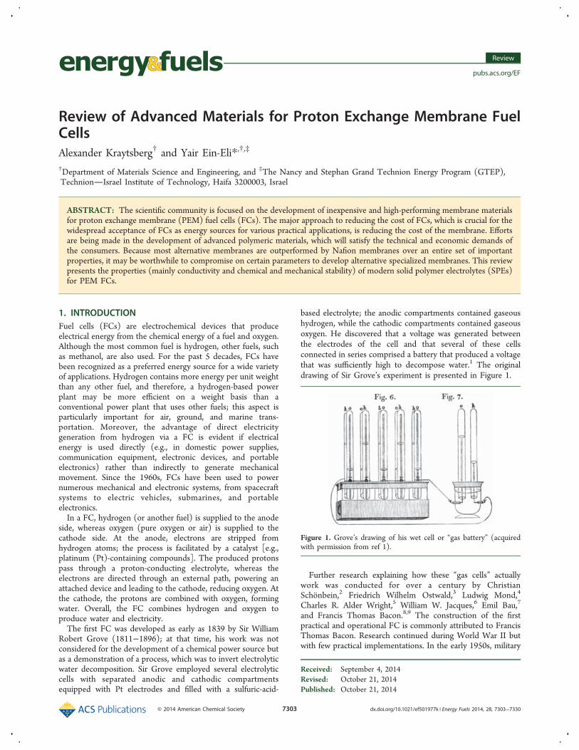
Robert Grove (1811−1896); at that time, his work was notconsidered for the development of a chemical power source butas a demonstration of a process, which was to invert electrolyticwater decomposition. Sir Grove employed several electrolyticcells with separated anodic and cathodic compartmentsequipped with Pt electrodes and filled with a sulfuric-acid-
based electrolyte; the anodic compartments contained gaseoushydrogen, while the cathodic compartments contained gaseousoxygen. He discovered that a voltage was generated betweenthe electrodes of the cell and that several of these cellsconnected in series comprised a battery that produced a voltagethat was sufficiently high to decompose water.1 The originaldrawing of Sir Grove’s experiment is presented in Figure 1.
Further research explaining how these “gas cells” actuallywork was conducted for over a century by ChristianSchonbein,2 Friedrich Wilhelm Ostwald,3 Ludwig Mond,4
Charles R. Alder Wright,5 William W. Jacques,6 Emil Bau,7
and Francis Thomas Bacon.8,9 The construction of the firstpractical and operational FC is commonly attributed to FrancisThomas Bacon. Research continued during World War II butwith few practical implementations. In the early 1950s, military
Received: September 4, 2014Revised: October 21, 2014Published: October 21, 2014
Figure 1. Grove’s drawing of his wet cell or “gas battery” (acquiredwith permission from ref 1).
demands for a robust power supply for space and mobileapplications began to promote the idea of producing electricityvia an electrochemical process that used atmospheric or storedoxygen and employed a device without moving parts. Becausethese technological improvements were designed for space andmilitary applications, the research costs were often of secondaryimportance. Because air is not available in space or underwaterand it is impractical to store oxygen for internal combustionengines, chemical power sources (i.e., batteries) may serve asreliable power sources.The conventional batteries of the 1950s were extremely
heavy. This fact stimulated the National Aeronautics and SpaceAdministration (NASA) to develop FCs as a provisionalchemical power source. The full implementation of FCs insubmarines required an additional 40 years, with the first non-nuclear, air-independent-propulsion submarines entering serv-ice in European fleets in the early 2000s.FCs with solid polymer electrolyte (SPE) membranes
separating the anodic (fuel) compartment from the cathodic(oxidant) compartment were first introduced in the Geminispace program in the early 1960s. Those cells were expensiveand had short lifetimes because of the poor stability of the SPEmembranes. The sulfonated polystyrene−divinylbenzene mem-branes suffered from rapid oxidative degradation. Additionally,this material was prohibitively expensive for practicalcommercial applications.Commercial applications of FCs gradually became more
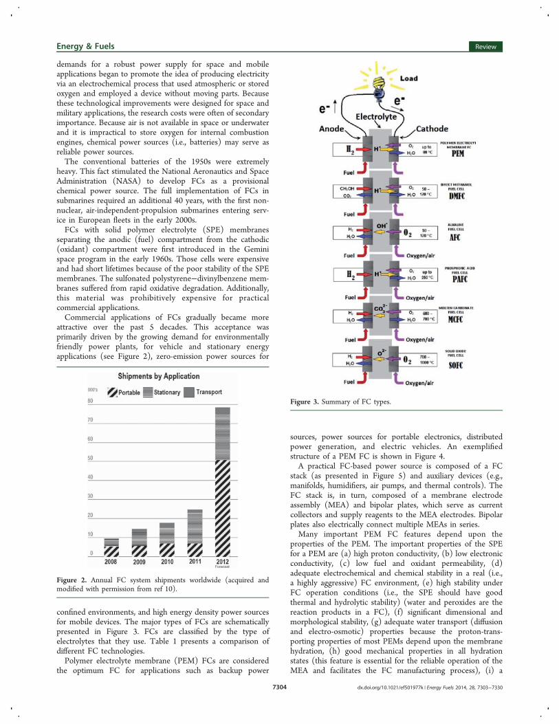
attractive over the past 5 decades. This acceptance wasprimarily driven by the growing demand for environmentallyfriendly power plants, for vehicle and stationary energyapplications (see Figure 2), zero-emission power sources for
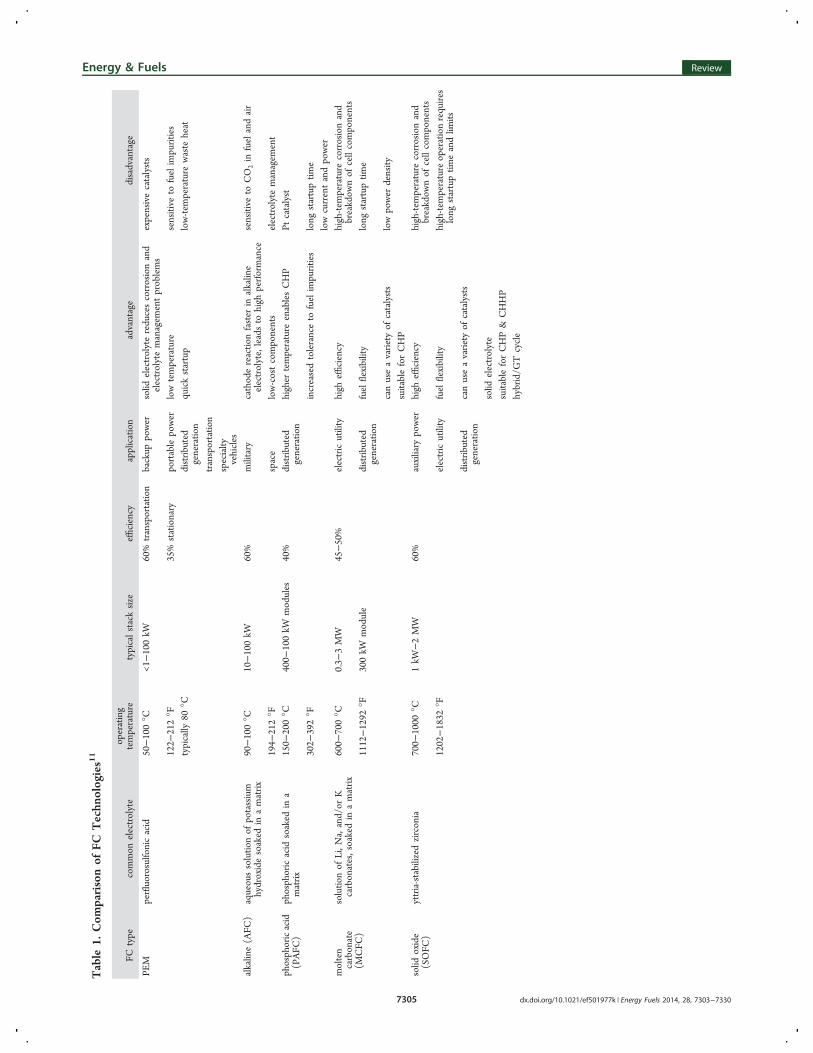
confined environments, and high energy density power sourcesfor mobile devices. The major types of FCs are schematicallypresented in Figure 3. FCs are classified by the type ofelectrolytes that they use. Table 1 presents a comparison ofdifferent FC technologies.Polymer electrolyte membrane (PEM) FCs are considered
the optimum FC for applications such as backup power
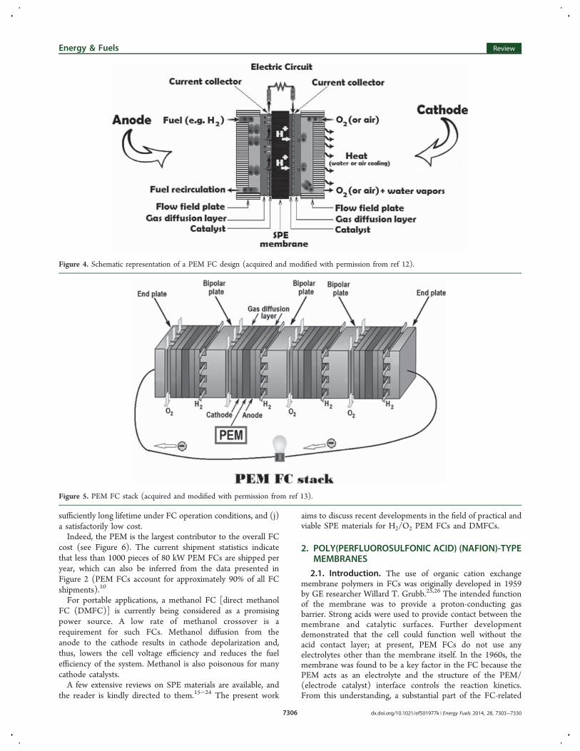
sources, power sources for portable electronics, distributedpower generation, and electric vehicles. An exemplifiedstructure of a PEM FC is shown in Figure 4.A practical FC-based power source is composed of a FC
stack (as presented in Figure 5) and auxiliary devices (e.g.,manifolds, humidifiers, air pumps, and thermal controls). TheFC stack is, in turn, composed of a membrane electrodeassembly (MEA) and bipolar plates, which serve as currentcollectors and supply reagents to the MEA electrodes. Bipolarplates also electrically connect multiple MEAs in series.Many important PEM FC features depend upon the
properties of the PEM. The important properties of the SPEfor a PEM are (a) high proton conductivity, (b) low electronicconductivity, (c) low fuel and oxidant permeability, (d)adequate electrochemical and chemical stability in a real (i.e.,a highly aggressive) FC environment, (e) high stability underFC operation conditions (i.e., the SPE should have goodthermal and hydrolytic stability) (water and peroxides are thereaction products in a FC), (f) significant dimensional andmorphological stability, (g) adequate water transport (diffusionand electro-osmotic) properties because the proton-trans-porting properties of most PEMs depend upon the membranehydration, (h) good mechanical properties in all hydrationstates (this feature is essential for the reliable operation of theMEA and facilitates the FC manufacturing process), (i) a
Figure 2. Annual FC system shipments worldwide (acquired andmodified with permission from ref 10).
Figure 3. Summary of FC types.
Energy & Fuels Review
dx.doi.org/10.1021/ef501977k | Energy Fuels 2014, 28, 7303−73307304
Table
1.Com
parisonof
FCTechn
ologies11
FCtype
common
electrolyte
operating
temperature
typicalstacksize
efficiency
application
advantage
disadvantage
PEM
perfluorosulfonicacid
50−100°C
<1−100kW
60%
transportatio
nbackup
power
solid
electrolytereducescorrosionand
electrolytemanagem
entproblems
expensivecatalysts
122−
212°F
35%
stationary
portablepower
lowtemperature
sensitive
tofuelimpurities
typically
80°C
distrib
uted
generatio
nquickstartup
low-tem
perature
waste
heat
transportatio
nspecialty
vehicles
alkaline(AFC
)aqueoussolutio
nof
potassium
hydroxidesoaked
inamatrix
90−100°C
10−100kW
60%
military
cathodereactio
nfaster
inalkaline
electrolyte,leadsto
high
performance
sensitive
toCO
2in
fuelandair
194−
212°F
space
low-costcomponents
electrolytemanagem
ent
phosphoricacid
(PAFC
)phosphoricacid
soaked
ina
matrix
150−
200°C
400−
100kW
modules
40%
distrib
uted
generatio
nhigher
temperature
enablesCHP
Ptcatalyst
302−
392°F
increasedtoleranceto
fuelimpurities
long
startuptim
elowcurrentandpower
molten
carbonate
(MCFC
)
solutio
nof
Li,N
a,and/or
Kcarbonates,soakedin
amatrix
600−
700°C
0.3−
3MW
45−50%
electricutility
high
efficiency
high-tem
perature
corrosionand
breakdow
nof
cellcomponents
1112−1292
°F300kW
module
distrib
uted
generatio
nfuelflexibility
long
startuptim
e
canuseavariety
ofcatalysts
lowpower
density
suitableforCHP
solid
oxide
(SOFC
)yttria-stabilized
zirconia
700−
1000
°C1kW
−2MW
60%
auxiliary
power
high
efficiency
high-tem
perature
corrosionand
breakdow
nof
cellcomponents
1202−1832
°Felectricutility
fuelflexibility
high-tem
peratureoperationrequires
long
startuptim
eandlim
itsdistrib
uted
generatio
ncanuseavariety
ofcatalysts
solid
electrolyte
suitableforCHP&
CHHP
hybrid/G
Tcycle
Energy & Fuels Review
dx.doi.org/10.1021/ef501977k | Energy Fuels 2014, 28, 7303−73307305
sufficiently long lifetime under FC operation conditions, and (j)a satisfactorily low cost.Indeed, the PEM is the largest contributor to the overall FC
cost (see Figure 6). The current shipment statistics indicatethat less than 1000 pieces of 80 kW PEM FCs are shipped peryear, which can also be inferred from the data presented inFigure 2 (PEM FCs account for approximately 90% of all FCshipments).10
For portable applications, a methanol FC [direct methanolFC (DMFC)] is currently being considered as a promisingpower source. A low rate of methanol crossover is arequirement for such FCs. Methanol diffusion from theanode to the cathode results in cathode depolarization and,thus, lowers the cell voltage efficiency and reduces the fuelefficiency of the system. Methanol is also poisonous for manycathode catalysts.A few extensive reviews on SPE materials are available, and
the reader is kindly directed to them.15−24 The present work
aims to discuss recent developments in the field of practical andviable SPE materials for H2/O2 PEM FCs and DMFCs.
2.1. Introduction. The use of organic cation exchangemembrane polymers in FCs was originally developed in 1959by GE researcher Willard T. Grubb.25,26 The intended functionof the membrane was to provide a proton-conducting gasbarrier. Strong acids were used to provide contact between themembrane and catalytic surfaces. Further developmentdemonstrated that the cell could function well without theacid contact layer; at present, PEM FCs do not use anyelectrolytes other than the membrane itself. In the 1960s, themembrane was found to be a key factor in the FC because thePEM acts as an electrolyte and the structure of the PEM/(electrode catalyst) interface controls the reaction kinetics.From this understanding, a substantial part of the FC-related
Figure 4. Schematic representation of a PEM FC design (acquired and modified with permission from ref 12).
Figure 5. PEM FC stack (acquired and modified with permission from ref 13).
Energy & Fuels Review
dx.doi.org/10.1021/ef501977k | Energy Fuels 2014, 28, 7303−73307306
research was focused on improving PEM properties, developinga stronger, more durable, and flexible SPE, and increasing SPEproton conductivity.Currently, Nafion is the PEM that serves as a benchmark in
the FC industry. This material was developed in the late 1960sby Dr. Walther Grot from DuPont (this material was originallysuggested to be employed as a permselective separator inchloralkali electrolyzers).27 Nafion was developed by modifyinganother DuPont product, Teflon,28 which was the first syntheticpolymer with ionic properties (ionomers) ever developed. Ionicproperties are impelled to Nafion by adding a pendant sulfonicacid group into the polymer backbone. The exemplifiedstructure of Nafion is shown in Figure 7, where the sulfonic
acid group is shown in its anhydrous form, SO3H. Whenexposed to water, the hydrolyzed form (SO3
−H3O+) appears,
allowing for proton transport across the material.Commercial Nafion membranes with thicknesses of 2, 5, 7,
and 10 mil (1 mil = 25.4 μm; Nafion 112, 115, 117, and 1110,respectively) appear to be the most widely used grades ofNafion. This material provides high proton conductivity andmoderate water swelling. The thinner membranes are generallyapplied to hydrogen/air applications to minimize ohmic losses,whereas the thicker membranes are employed for DMFCs formethanol crossover reduction.22
Being similar to Teflon, Nafion exhibits excellent resistanceto chemical attacks and an extremely low release rate ofdegradation products into the surrounding medium; it also hasa relatively high operation temperature range and may be used
in many applications at temperatures up to 190 °C. Nafion hasa high proton conductivity and acts as a superacid catalystbecause its sulfonic acid groups act as an extremely strongproton donor. The interaction of sulfonic acid groups withwater results in rapid water absorption and water transportthrough the Nafion material.
2.2. Nafion Membrane Conductivity. Hydrophilicsulfonic groups, which are side-attached to the fluorinatedhydrophobic backbone of Nafion, may be subjected tohydration; i.e., water molecules may accumulate around thesegroups. Water affects the Nafion proton conductivity bycontrolling the formation, dimensions, and connectivity ofproton pathways in Nafion. As more water molecules becomeavailable, these water clusters grow in size and the Nafionmaterial separates into hydrophobic regions and water-filledhydrophilic domains.30−35 Nafion with a low water contentcontains only small isolated water clusters and behaves as aninsulator. Eventually, a percolation threshold of protonconductivity is passed. At this point, the water clusters areconnected in a random network embedded in a continuous,sponge-like fluorocarbon phase. However, most of the watermolecules are still located at the borders of the clusters, andthus, most of the water molecules inside the percolationchannels accumulate in sulfonate group solvation shells. Thisleads to a high activation energy for proton transfer, whichimpedes a “hop-turn” (i.e., Grotthuss-type) proton conductivityand results in a primarily proton-diffusion-based conductivity.At the same time, the low proton mobility results in smallproton conductivity. As the water content increases, thechannels become broader and more free water moleculesbecome available. However, the strong electrostatic interactionbetween the hydronium ions and multiple sulfonate groups stillimpedes Grotthuss-type proton conductivity and results in apredominantly diffusion-based proton conductivity. Under thishydration state, proton mobility is a key factor that determinesthe proton conductivity.As the water content increases, the water clusters and
channels increase in size and the amount of available free waterinside the aqueous phase increases. This results in an increasingdominance of the Grotthuss-type conductivity, which increasesproton transport capabilities. Once Nafion becomes fullysaturated with water, its structure is patterned with highly
Figure 6. Breakdown of the 2013 projected FC stack cost at 1000/year production of 80 kW systems (data acquired with permission from ref 14).
Figure 7. Nafion formula (acquired and modified with permissionfrom ref 29).
Energy & Fuels Review
dx.doi.org/10.1021/ef501977k | Energy Fuels 2014, 28, 7303−73307307
interconnected water channels and nearly spherical smallhydrophilic domains containing water drops. These nearlyspherical domains are surrounded by the hydrophobic polymerbackbone chains, with the hydrophilic ionic groups located atthe interface. A well-developed percolated network is formed,with the network comprising channels filled with free water.Thus, a saturated Nafion membrane resembles a phase-separated system containing hydrophobic main chain agglom-erates and hydrophilic water/acid segments. The protonconductivity of the Nafion membrane approaches a valueclose to the conductivities of bulk aqueous electrolytes, and theconductivity is controlled by a Grotthuss-type mechanism.DuPont’s Nafion is not entirely unique, and similarperfluorinated ionomers have been developed by othercompanies (e.g., Aciplex and Flemion of Asahi ChemicalCompany).36−38 Nafion-type perfluorinated ionomers withshorter pendant groups (such as AQUIVION of SolvaySolexis) are also currently marketed and appear to outperformNafion, having a lower methanol crossover and superior watermanagement.39,40
2.3. Nafion Membrane Drawbacks. Although Nafioncurrently dominates the market, particularly in FC design andproduction,41 it has some serious drawbacks. (a) Because theproton conductivity is determined by the water-filled channels,Nafion is not adequate for temperatures materially lower than 0°C or significantly over 100 °C.42,43 (b) Nafion is seeminglystable against peroxide-type ion and radical degradation (whichare intermediate products of the reactions at the electrodes ofthe FC);44 e.g., it is stable against 30% H2O2 even at 80 °C.However, alien cations (i.e., other than H+) are known tocatalyze the polymer chain decomposition.45,46 Additionally, afew of the hydrogen-containing terminal groups of the polymerare susceptible to peroxide radical attacks.47 (c) Contaminatingions, especially multi-charged ions,44,48 may also drasticallydecrease the membrane conductivity and decrease the watercontent of the Nafion membrane.44,49 Thus, alien ion impuritiesshould be minimized during membrane production andoperation. (d) Nafion has poor mechanical and chemicalstabilities at elevated temperatures.50−53 Being a part of anassembled MEA, the membrane suffers from severe degradationin the course of multiple thermal and hydration/dehydrationcycles.54−56 Because membrane mechanical degradation istypically the limiting parameter in determining FC lifetimes,substantial efforts were made to avoid or at least minimize thistype of degradation. The membrane operational life also largelydepends upon the MEA design and MEA assemblyprocess.57−59 The appropriate routes for improving themechanical stability of a Nafion membrane are through theprecise controls of membrane swelling, temperature, andtemperature gradient36,60−63 and the reinforcement of themembranes with an inert matrix,64−66 which may be composedof a polymer structure36,50,67−75 or an inorganic matrix.Composite membranes comprising Nafion and inorganic fillershave been used. This is the general method to improve themembrane chemical and temperature stabilities the method isless commonly used to enhance the membrane mechanicalstability.36,65,76−82 The introduction of a reinforcing matrixtypically decreases the membrane-specific conductivity andwater vapor permeability. These changes appear because a partof Nafion is substituted with the matrix material, which isimpermeable to water and protons. The effects of the matrixextend beyond a simple substitution of a portion of an activematerial with inert media. An inert matrix-embedded Nafion
membrane may have lower proton conductivity and watervapor permeability than bulk Nafion because of a decrease inthe membrane connectivity and because of the matrix-restrictedmacromolecular transport.70 However, several additives may beused to enhance the proton conductivity of the reinforcedNafion membranes (e.g., phosphotungstic acid).83 The employ-ment of a reinforcing matrix may result in an increase in theoverall membrane conductivity because the reinforced mem-brane may be substantially thinner than the Nafionmembrane.60 The presence of inorganic fillers with graftedfunctional groups is more efficient and enhances the overallcomposite membrane properties, such as water uptake, ionexchange capacity (IEC), and conductivity, while maintainingthe mechanical properties of the composite membrane. Theshape of the inorganic fillers also strongly affects the propertiesof the composite membranes.84 Surface treatments may alsoresult in the improvement of membrane mechanical proper-ties.85,86 (e) Nafion has insufficient resistance to methanolcrossover. This feature stems from the fact that, although thewater-filled network provides a path for proton transfer, it alsoprovides a route for methanol diffusion. This drawback ofNafion may be addressed by the addition of fine inorganicparticles to the polymer matrix.87 Another way to overcome thehigh methanol permeability of Nafion is to introduce otherpolymers with different properties inside the Nafion voidspace.88 There are two approaches to such a modification: thefirst approach suggests the introduction of individual polymermolecules inside the voidspace (i.e., semi-interpenetratingpolymer networks or a semi-IPN architecture),88−90 and thesecond approach suggests the introduction of an intercon-nected polymer net comprising cross-linked polymer molecules(i.e., interpenetrating polymer network or IPN).91 The highmethanol permeability of Nafion is an issue, particularly if aPEM DMFC uses only this membrane. (f) The cost of a SPE iscritical from a practical perspective. Nafion membranes areprohibitively expensive because of their complex manufacturingprocess.
3. NON-NAFION SPE
The development of Nafion in the early 1960s was followed bya significant decline in the development of non-Nafion SPEmaterials in subsequent decades. However, the aforementioneddrawbacks (particularly the high price of Nafion) has become adriving force for the development of new polymer electrolytes,which are expected to be more affordable, more mechanicallyand chemically stable, and less permeable to methanolcompared to Nafion. There has also been a growing demandfor materials capable of operating at high (>100 °C) andmedium (>80 °C) temperatures with high conductivity at lowhydration levels. The operation of FCs at elevated temperaturesoffers several substantial advantages.20,40,92−95
First, the commonly used Pt-based catalysts are poisoned bycarbon monoxide (CO) at low operational temperatures;unfortunately, CO is often present in fuel-grade H2. Thisrequires an expensive H2 fuel purification process for PEM FCs.At high temperatures (particularly at temperatures aboveapproximately 160 °C), catalyst poisoning does not occurand the cell may tolerate up to 3% CO in the H2 fuel withoutsignificant power losses.40,96 Second, faster electrode kineticsare expected at elevated temperatures, which increases the FCefficiency. Third, the absence of biphasic water (vapor andliquid) simplifies water management.
Energy & Fuels Review
dx.doi.org/10.1021/ef501977k | Energy Fuels 2014, 28, 7303−73307308
Modern SPE-related research is focused on the followingareas: (a) developing SPEs for H2/O2 FCs with high operationtemperatures (such SPEs are expected to operate under low-humidity conditions), (b) developing SPEs for DMFCs withhigh protonic conductivity but low methanol permeability, and(c) developing low-cost substitutes for Nafion-type membranes.Numerous partially fluorinated SPE and non-fluorinated
(hydrocarbon) SPE materials have been investigated97 (ref 98provides an extensive review of methods using such SPEs).These SPE materials have similar proton conductivitymechanisms as Nafion. However, these materials maypotentially offer advantages over Nafion depending upon thepresence of water inside the polymer,99−101 the specifics ofproduction costs, water management, methanol crossover, andthermal cycling stability.3.1. Polystyrene-Based Membranes. Polystyrene−sul-
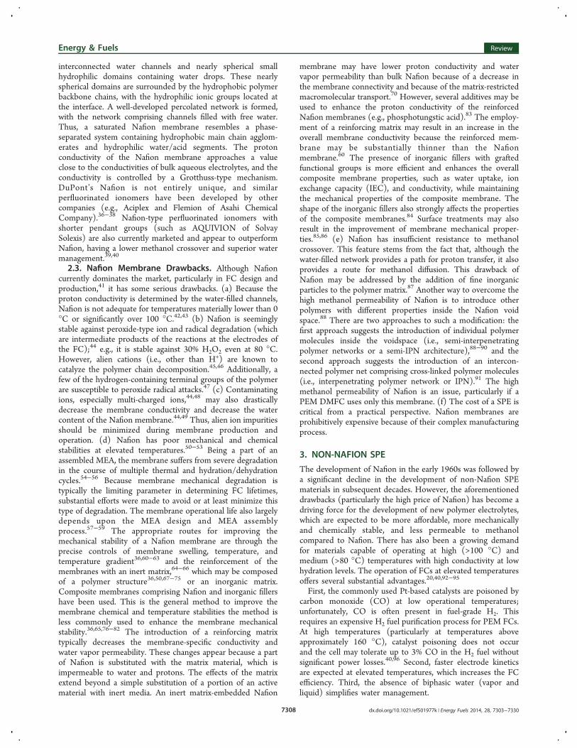
fonic acid (PSSA) membranes were the first commercialpolymer membranes25 (see Figure 8). The first polystyrenemembranes were developed in 1955 by GE and were used inthe first-ever operational PEM FC (the Grubb−Niedrach FC)in the Gemini program.102,103 However, the system exhibited ashort lifetime (<200 h) because of membrane degradation, andthe emergence of Nafion reduced interest in the developmentof polystyrene-based membrane materials.The call for materials with medium and high operating
temperatures and with high conductivity at low water contentshas revived the interest in polystyrene-based membrane
materials.22 Given that the cost of SPE is a focus of the FCindustry, the attractive feature of PSSA-based membranes isthat polystyrene, its derivatives, and many styrene-containingcopolymers are relatively inexpensive. Furthermore, themethanol permeability of PSSA-based membranes is lowerthan that of Nafion104,105 (i.e., the methanol selectivity β106 ofthe PSSA membrane is larger).However, PSSA membranes are unstable107 under practical
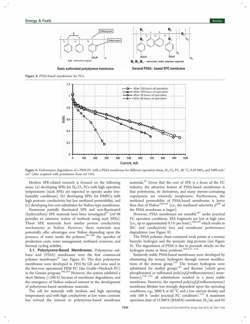
FC operation conditions. SSA fragments are lost at high rates(i.e., up to approximately 0.1% per hour),108,109 which results inIEC and conductivity loss and membrane performancedegradation (see Figure 9).The PSSA polymer chain contained weak points at a ternary
benzylic hydrogen and the aromatic ring protons (see Figure8). The degradation of PSSA is due to peroxide attacks on thehydrogen atoms in these positions.104,111−114
Relatively stable PSSA-based membranes were developed byeliminating the ternary hydrogens through various modifica-tions of the styrene group.115 The ternary hydrogens weresubstituted for methyl groups112 and fluorine [which givesphosphonated or sulfonated poly(α,β,β-trifluorostyrene) mem-branes];116−123 all substitutions resulted in a more stablemembrane. However, the reported poly(α,β,β-trifluorostyrene)membrane lifetime was strongly dependent upon the operatingconditions, e.g., 3000 h at 50 °C and a low current density andonly 500 h “under practical FC conditions”.119 A maximumoperation time of 15 000 h (BAM3G membrane, H2/air, and 85
Figure 8. PSSA-based membranes for FCs.
Figure 9. Performance degradation of a PEM FC with a PSSA membrane for different operation times, H2/O2 FC, 80 °C, 0.20 MPa, and 1000 mA/cm2 (data acquired with permission from ref 110).
Energy & Fuels Review
dx.doi.org/10.1021/ef501977k | Energy Fuels 2014, 28, 7303−73307309
°C) was reported for the pre-commercial BAM3G series SPEmembranes. These membranes contained (α,β,β-trifluorostyr-ene)-sulfonated pendant groups and perfluorinated backbones(see Figure 10).101,119,123 BAM membranes also demonstratedfair conductivity values of between 5 × 10⁻² and 9 × 10⁻² S/cm.101
We were unable to find substantial information on the criticalparameters of these membranes (e.g., available thickness andmechanical strength). These membranes may not becommercially available. Because this material is partiallyfluorinated, it is expected to have several of the samedisadvantages as Nafion membranes, such as being non-environmentally friendly, which poses a problem with theirsafe production and disposal. The costs and unit pricing forthese membranes were also not available. The PSSA-basedmembrane material has a substantially higher water contentthan Nafion membranes but a lower conductivity (see Figure11).101,124 These conductivity values are still acceptable for FCapplications.This suggests that PSSA-based materials offer a slimmer and
less interlinked water-filled network (the presence of such ahydrophilic network is now considered a requirement for SPEproton conductivity125). The amount of sulfonic acid functionalgroups is also lower. These factors result in unfavorable
material swelling and a steep decline in conductivity with adecreasing membrane water content. However, the electro-osmotic water drag is expected to be advantageously reduced incomparison to Nafion.126 The attempts to control theseparameters of a PSSA-based SPE led to the use of variousSSA copolymers127,128 [using polymers with various (R1)groups of different lengths (n3); see Figure 8] because thefeatures of the SPE depend upon the properties of the polymerbackbone.31,129
SPEs containing various SSA copolymers, including sulfo-nated poly(styrene-block-isobutylene-block-styrene) triblockcopolymers,130,131 sulfonated polystyrene-block-(ethylene-ran-butylene)-block-polystyrene,132,133 sulfonated styrene−ethylenecopolymers,134 sulfonated polystyrene(ethylene−butylene)-polystyrene triblock copolymers,135 ,136 and poly-[norbornenylethylstyrene-s-styrene]-poly(n-propyl-p-styrene-sulfonate) (PNS−PSSP) block polymers,137 were prepared andinvestigated. These SPEs often demonstrated higher protonconductivity (up to 10−1 S/cm) than Nafion. These materialsalso often demonstrated superior methanol selectivity com-pared to Nafion. However, the stability data for thesemembranes were typically not reported in the literature, andthe applicability of PSSA-co-polymer polymers in FCs is likelylimited because the sulfonated polystyrene unit has a rather lowoxidative stability.The next step was to graft oligomer SSA fragments onto the
backbone of a highly stable polymer. Such grafted polymermembranes offered a substantially higher IECs with moderateswelling because these membranes possessed isotropicallyconnected ionic domains with high proton concentrations.Block copolymer membranes swelled excessively even at lowIEC, which resulted in lower proton concentrations andconductivity. This prevented copolymer-based SPEs fromattaining a high IEC; furthermore, high hydration compromisedmembrane mechanical properties.138
Next, polystyrene SSA-grafted membranes were investi-gated.139−141 These membranes were synthesized by thepreliminary preparation of SSA−oligomer segments, followedby their copolymerization with styrene. The preparedmembranes demonstrated high proton conductivity (up to0.24 S/cm), and these results have stimulated furtherdevelopment in the field.Stable polymers, such as tetrafluoroethylene (PTFE, Teflon),
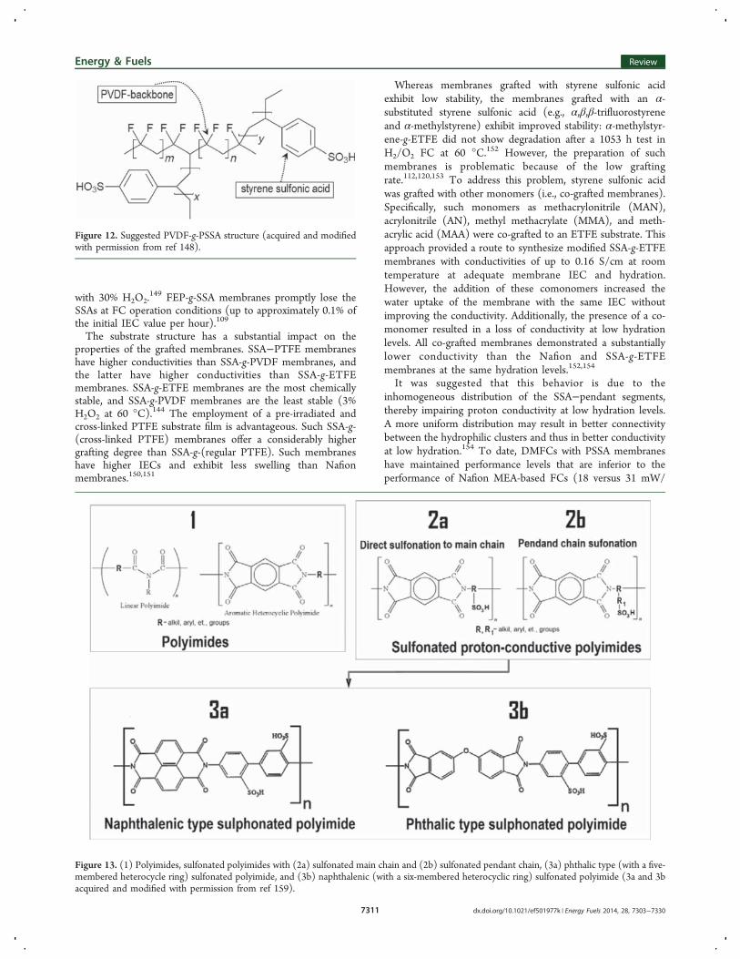
poly(tetrafluoroethylene-co-hexafluoropropylene) (FEP), poly-(tetrafluoroethylene-co-perfluoropropyl vinyl ether) (PFA),polyvinylidene fluoride (PVDF), poly(vinylidene fluoride-co-hexafluoropropylene) (PVDF-co-HEP), poly(ethylene-alt-tetra-fluoroethylene) (ETFE), polyvinyl fluoride (PVF), and poly-ethylene, present attractive skeleton structures for SSA-graftedmembranes.120,142−145 Radiation-induced grafting is a commonmethod for the preparation of such polymers with SSA andmodified SSA segments.PVDF-g-SSA membranes (see Figure 12) demonstrated
good proton conductivity (up to 0.13 S/cm). Unfortunately,these membranes exhibited substantially higher water absorp-tion (up to 59 water molecules per SO3 unit) than Nafion,which is a disadvantage for SPE materials.146,147
Teflon-g-SSA, (low-density polyethylene)-g-SSA, and [tetra-fluoroethylene-co-perfluoropropylene (FEP, Teflon 100)]-g-SSA materials were prepared by radiation-induced graftingand also demonstrated initial conductivities in the range from0.1 × 10−2 to 10 × 10−2 S/cm, but the conductivity diminishedby several orders of magnitude after treating the membranes
Figure 10. General structure of the sulfonated poly(α,β,β-trifluor-ostyrene) BAM3G membrane (acquired with permission from ref119).
Figure 11. Proton conductivity versus water content for PSSA materialwith different degrees of sulfonation and for Nafion 117 (acquired andmodified with permission from ref 124).
Energy & Fuels Review
dx.doi.org/10.1021/ef501977k | Energy Fuels 2014, 28, 7303−73307310
with 30% H2O2.149 FEP-g-SSA membranes promptly lose the
SSAs at FC operation conditions (up to approximately 0.1% ofthe initial IEC value per hour).109
The substrate structure has a substantial impact on theproperties of the grafted membranes. SSA−PTFE membraneshave higher conductivities than SSA-g-PVDF membranes, andthe latter have higher conductivities than SSA-g-ETFEmembranes. SSA-g-ETFE membranes are the most chemicallystable, and SSA-g-PVDF membranes are the least stable (3%H2O2 at 60 °C).144 The employment of a pre-irradiated andcross-linked PTFE substrate film is advantageous. Such SSA-g-(cross-linked PTFE) membranes offer a considerably highergrafting degree than SSA-g-(regular PTFE). Such membraneshave higher IECs and exhibit less swelling than Nafionmembranes.150,151
Whereas membranes grafted with styrene sulfonic acidexhibit low stability, the membranes grafted with an α-substituted styrene sulfonic acid (e.g., α,β,β-trifluorostyreneand α-methylstyrene) exhibit improved stability: α-methylstyr-ene-g-ETFE did not show degradation after a 1053 h test inH2/O2 FC at 60 °C.152 However, the preparation of suchmembranes is problematic because of the low graftingrate.112,120,153 To address this problem, styrene sulfonic acidwas grafted with other monomers (i.e., co-grafted membranes).Specifically, such monomers as methacrylonitrile (MAN),acrylonitrile (AN), methyl methacrylate (MMA), and meth-acrylic acid (MAA) were co-grafted to an ETFE substrate. Thisapproach provided a route to synthesize modified SSA-g-ETFEmembranes with conductivities of up to 0.16 S/cm at roomtemperature at adequate membrane IEC and hydration.However, the addition of these comonomers increased thewater uptake of the membrane with the same IEC withoutimproving the conductivity. Additionally, the presence of a co-monomer resulted in a loss of conductivity at low hydrationlevels. All co-grafted membranes demonstrated a substantiallylower conductivity than the Nafion and SSA-g-ETFEmembranes at the same hydration levels.152,154
It was suggested that this behavior is due to theinhomogeneous distribution of the SSA−pendant segments,thereby impairing proton conductivity at low hydration levels.A more uniform distribution may result in better connectivitybetween the hydrophilic clusters and thus in better conductivityat low hydration.154 To date, DMFCs with PSSA membraneshave maintained performance levels that are inferior to theperformance of Nafion MEA-based FCs (18 versus 31 mW/
Figure 12. Suggested PVDF-g-PSSA structure (acquired and modifiedwith permission from ref 148).
Figure 13. (1) Polyimides, sulfonated polyimides with (2a) sulfonated main chain and (2b) sulfonated pendant chain, (3a) phthalic type (with a five-membered heterocycle ring) sulfonated polyimide, and (3b) naphthalenic (with a six-membered heterocyclic ring) sulfonated polyimide (3a and 3bacquired and modified with permission from ref 159).
Energy & Fuels Review
dx.doi.org/10.1021/ef501977k | Energy Fuels 2014, 28, 7303−73307311
cm2), despite the lower methanol permeability of PSSAmembranes.155
3.2. Sulfonated Polyimide (SPI)-Based Membranes.Polyimides are a family of thermostable polymers, featuring acombination of high mechanical and thermal properties and adurability against aggressive chemicals and heat.22,23,156−158
These polymers are typically good insulators and may bemodified with sulfonic groups. This modification impartshydrophilicity and proton conductivity. The two routes forthe sulfonation of polyimides are illustrated in Figure 13:sulfonation of the main polymer chain and sulfonation of thependant polymer chains.158
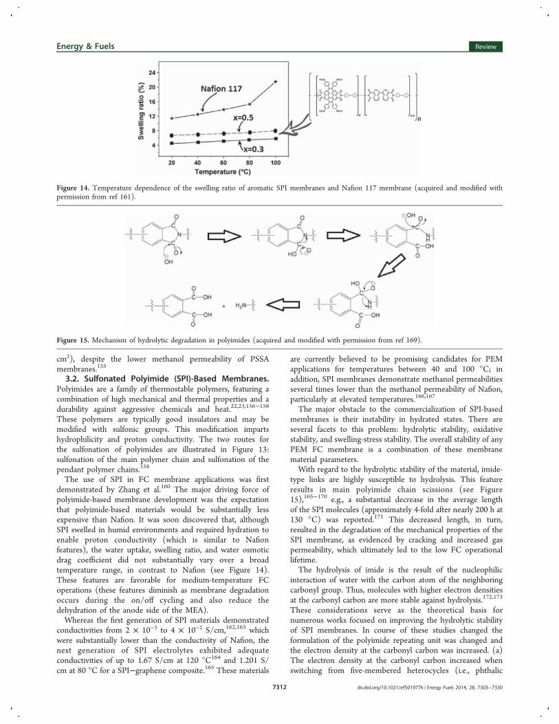
The use of SPI in FC membrane applications was firstdemonstrated by Zhang et al.160 The major driving force ofpolyimide-based membrane development was the expectationthat polyimide-based materials would be substantially lessexpensive than Nafion. It was soon discovered that, althoughSPI swelled in humid environments and required hydration toenable proton conductivity (which is similar to Nafionfeatures), the water uptake, swelling ratio, and water osmoticdrag coefficient did not substantially vary over a broadtemperature range, in contrast to Nafion (see Figure 14).These features are favorable for medium-temperature FCoperations (these features diminish as membrane degradationoccurs during the on/off cycling and also reduce thedehydration of the anode side of the MEA).Whereas the first generation of SPI materials demonstrated
conductivities from 2 × 10⁻³ to 4 × 10⁻² S/cm,162,163 whichwere substantially lower than the conductivity of Nafion, thenext generation of SPI electrolytes exhibited adequateconductivities of up to 1.67 S/cm at 120 °C164 and 1.201 S/cm at 80 °C for a SPI−graphene composite.165 These materials
are currently believed to be promising candidates for PEMapplications for temperatures between 40 and 100 °C; inaddition, SPI membranes demonstrate methanol permeabilitiesseveral times lower than the methanol permeability of Nafion,particularly at elevated temperatures.166,167
The major obstacle to the commercialization of SPI-basedmembranes is their instability in hydrated states. There areseveral facets to this problem: hydrolytic stability, oxidativestability, and swelling-stress stability. The overall stability of anyPEM FC membrane is a combination of these membranematerial parameters.With regard to the hydrolytic stability of the material, imide-
type links are highly susceptible to hydrolysis. This featureresults in main polyimide chain scissions (see Figure15),165−170 e.g., a substantial decrease in the average lengthof the SPI molecules (approximately 4-fold after nearly 200 h at130 °C) was reported.171 This decreased length, in turn,resulted in the degradation of the mechanical properties of theSPI membrane, as evidenced by cracking and increased gaspermeability, which ultimately led to the low FC operationallifetime.The hydrolysis of imide is the result of the nucleophilic
interaction of water with the carbon atom of the neighboringcarbonyl group. Thus, molecules with higher electron densitiesat the carbonyl carbon are more stable against hydrolysis.172,173
These considerations serve as the theoretical basis fornumerous works focused on improving the hydrolytic stabilityof SPI membranes. In course of these studies changed theformulation of the polyimide repeating unit was changed andthe electron density at the carbonyl carbon was increased. (a)The electron density at the carbonyl carbon increased whenswitching from five-membered heterocycles (i.e., phthalic
Figure 14. Temperature dependence of the swelling ratio of aromatic SPI membranes and Nafion 117 membrane (acquired and modified withpermission from ref 161).
Figure 15. Mechanism of hydrolytic degradation in polyimides (acquired and modified with permission from ref 169).
Energy & Fuels Review
dx.doi.org/10.1021/ef501977k | Energy Fuels 2014, 28, 7303−73307312
polyimides) to six-membered heterocycles (i.e., naphthalenicpolyimides). This results in naphthalenic polyimides withhigher hydrolytic stability.159,167,174,175 (b) The electron densitydistribution may be changed by the introduction of bulkyaliphatic fragments in both the main chain and pendantfragments.176,177 (c) The electron density on carbonyl may alsobe increased by introducing “bridging” electron-donating sulfurin the main polyimide chain. This sulfur substantially decreasesthe electrophilicity of the carbonyl carbon, and such modifiedpolyimides demonstrate a higher resistance to hydroly-sis.178−180 (d) Electron-donating phenoxy groups can also beintroduced into the imide rings. These groups decrease theelectrophilicity of the imide rings, thus enhancing theirsusceptibility to hydrolysis.181 Additionally, the benzophenonegroup at the meta position of the imide group positivelyinfluences on the hydrolytic stability of the SPI materials.182 (e)The electron density on the carbonyl carbons of thenaphthalimide ring strongly depends upon the monomerstructure. If the main chain of the polyimide comprisesmonomer units with a common aromatic moiety (type A inFigure 14), it actually contains four carbonyl groups in the samearomatic system. This structure offers a lower electron densityfor each amide group than in the case of the monomer unitscomposed of two naphtyl rings separated by an aliphatic-typelink (type B in Figure 16). As a result, the binaphtylimide
configuration decreases the possibility of a nucleophilic attackat this position. This enhances the material hydrolytic stability,and SPIs of type B have an improved hydrolytic stabilitycompared to SPIs of type A.183,184 (f) Because the sulfonic acidgroup is a strong electron-withdrawing group, the distancingfrom the imide is also expected to result in an increase in thehydrolytic stability of the polyimide main chain. Indeed, themembranes, which are made of SPIs with sulfonated pendantchains, were found to be more stable when compared to asimilar main chain of sulfonated polyimides.177,186 (g) Incontrast, the introduction of trifluoromethyl groups, which havea strong electron-withdrawing ability, compromised the stabilityof the imide group.187 (h) The hydrolysis reaction of the imiderings was found to be equilibrated by a reverse condensationreaction.188 This is the basis of the assumption that the mainpolyamide chain may be regenerated. The rigidity of the main
polymer chain helped the two ends of the scissoned chainremain to be close to one another and, thus, assist in chainrepolymerization.189 This assumption was supported by theobservations that, in the case of the cross-linked SPIs withdifferent cross-linker alkyl chain lengths, the hydrolyticresistance of the membrane decreased with an increased alkylchain length (i.e., with an increased polymer net flexibility).190
With regard to swelling-stress stability, it is commonlyaccepted that water absorption causes polymer chain tension,which results in SPE degradation. The conductivity of a proton-conductive SPE was found to increase with an increasingmaterial water content.191 The latter is particularly true withrespect to the SPIs, which have a substantially lowerconductivity than Nafion at low water contents. Nafioncontains a substantial amount of small water clusters, even atan overall low water content. These clusters form channels forproton transport;34 this is not the case for the SPIs.186 Protonconductivity also increased with increasing IEC (i.e., the densityof the sulfonic acid groups).19 The water absorption of SPEmaterials also increased with increasing IEC because the SO3groups are strongly hydrophilic.192 This general provision isalso true for SPIs (e.g., the absorption of up to 12 watermolecules per acid group has been reported).193
Branched and/or cross-linked polymers counteract thehydration-related stresses better than their linear-chain counter-parts; such types of SPIs have been reported.190,194−197
Branched and/or cross-linked polymers have typically demon-strated higher degradation stability than their linear equivalents.Another way to reduce the polymer chain tension uponhydration is the use of flexible polyimide chains.198−202
However, although the polymer chain flexibility accommodatesthe mechanical stresses of water absorption, the flexibility alsointerferes with the repolymerization of the polyimide backbone(see point h). No solution to this issue has been found to date.Interestingly, it was recently found that compound
membranes comprising a porous spongy-like polyimide filmwith pores filled with a series of SPIs demonstrated higherhydrolytic stability than membranes prepared from these SPIswithout matrices.203
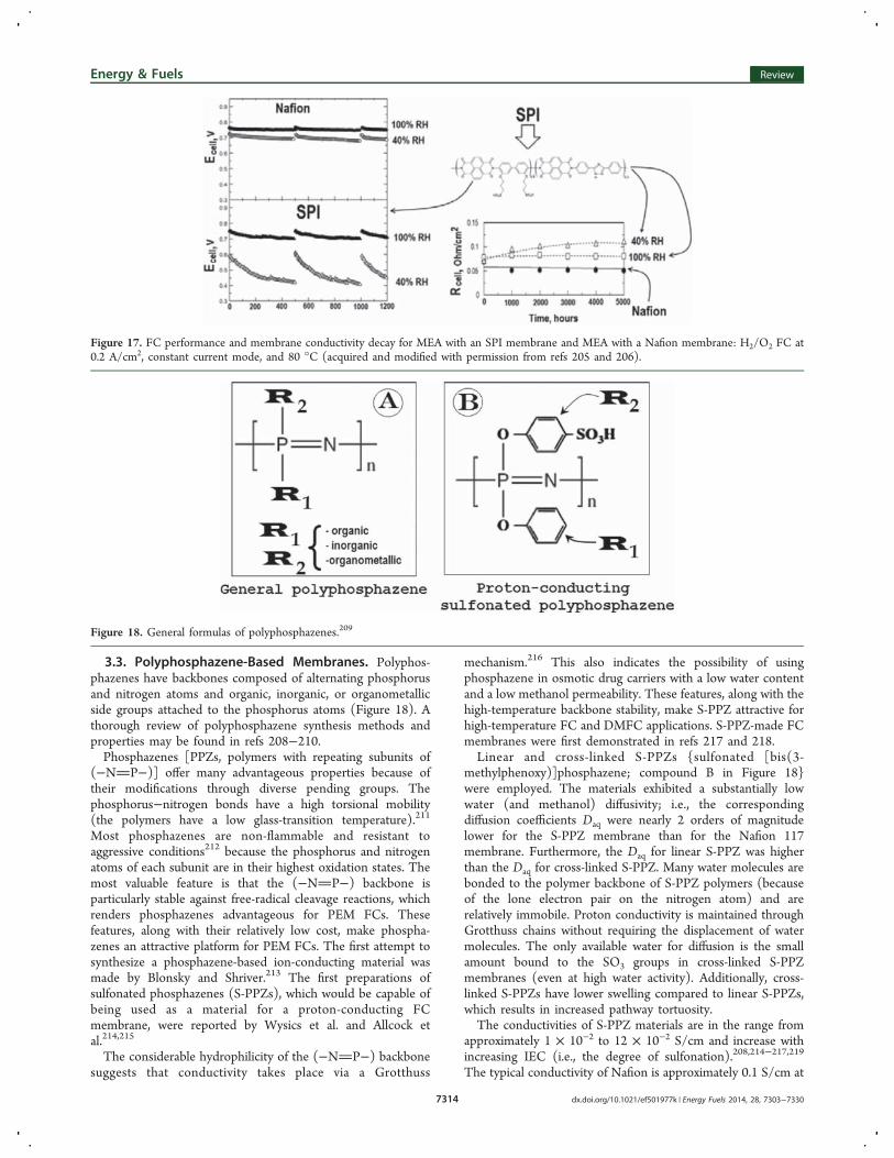
FCs (H2/O2 FC at 0.2 A/cm2) with various main-chainsulfonated polyimide membranes were tested between 60 and90 °C.204 The MEA lifetime strongly depended upon thetemperature and sulfonation. The MEA operational time wassmall at 90 °C. FCs (H2/O2 FC at 0.2 A/cm2 and 80 °C) withSPI with sulfonated pendant segments demonstrated substan-tially higher stability over 5000 h of operation.205,206 TheseMEAs demonstrated a fair performance; however, they wereoutperformed by a Nafion-based MEA (see Figure 17).FC testing (H2/O2 FC at 0.2 A/cm2 and 70 °C) revealed
that cross-linked sulfonated poly(imide-siloxane) MEAs per-form substantially better than Nafion 212 MEAs at lowerhumidification levels196 but have similar performance levels athigher humidification. Unfortunately, the authors did not reportdata on the operational lifetime of their MEAs. The SPI MEAperformance and conductivity also strongly depended upon theFC operational mode such that the membrane conductivity andFC performance degraded rapidly for a higher testing currentdensity.207
Although testing SPI MEA membranes using practical FCoperation conditions is an appropriate approach, the results ofthis testing are influenced by the stability of the membrane andthe stability of the membrane/catalyst interface.
Figure 16. SPIs with (A) monomer unit with common aromatic(naphtyl) system and (B) binaphthyl-type monomer unit, i.e., twonaphtyl rings separated with aliphatic-type link (acquired and modifiedwith permission from refs 183 and 185).
Energy & Fuels Review
dx.doi.org/10.1021/ef501977k | Energy Fuels 2014, 28, 7303−73307313
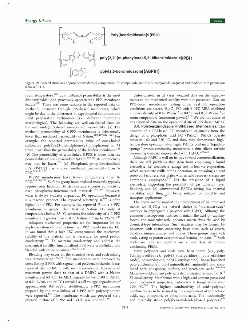
3.3. Polyphosphazene-Based Membranes. Polyphos-phazenes have backbones composed of alternating phosphorusand nitrogen atoms and organic, inorganic, or organometallicside groups attached to the phosphorus atoms (Figure 18). Athorough review of polyphosphazene synthesis methods andproperties may be found in refs 208−210.Phosphazenes [PPZs, polymers with repeating subunits of
(−NP−)] offer many advantageous properties because oftheir modifications through diverse pending groups. Thephosphorus−nitrogen bonds have a high torsional mobility(the polymers have a low glass-transition temperature).211
Most phosphazenes are non-flammable and resistant toaggressive conditions212 because the phosphorus and nitrogenatoms of each subunit are in their highest oxidation states. Themost valuable feature is that the (−NP−) backbone isparticularly stable against free-radical cleavage reactions, whichrenders phosphazenes advantageous for PEM FCs. Thesefeatures, along with their relatively low cost, make phospha-zenes an attractive platform for PEM FCs. The first attempt tosynthesize a phosphazene-based ion-conducting material wasmade by Blonsky and Shriver.213 The first preparations ofsulfonated phosphazenes (S-PPZs), which would be capable ofbeing used as a material for a proton-conducting FCmembrane, were reported by Wysics et al. and Allcock etal.214,215
The considerable hydrophilicity of the (−NP−) backbonesuggests that conductivity takes place via a Grotthuss
mechanism.216 This also indicates the possibility of usingphosphazene in osmotic drug carriers with a low water contentand a low methanol permeability. These features, along with thehigh-temperature backbone stability, make S-PPZ attractive forhigh-temperature FC and DMFC applications. S-PPZ-made FCmembranes were first demonstrated in refs 217 and 218.Linear and cross-linked S-PPZs {sulfonated [bis(3-
methylphenoxy)]phosphazene; compound B in Figure 18}were employed. The materials exhibited a substantially lowwater (and methanol) diffusivity; i.e., the correspondingdiffusion coefficients Daq were nearly 2 orders of magnitudelower for the S-PPZ membrane than for the Nafion 117membrane. Furthermore, the Daq for linear S-PPZ was higherthan the Daq for cross-linked S-PPZ. Many water molecules arebonded to the polymer backbone of S-PPZ polymers (becauseof the lone electron pair on the nitrogen atom) and arerelatively immobile. Proton conductivity is maintained throughGrotthuss chains without requiring the displacement of watermolecules. The only available water for diffusion is the smallamount bound to the SO3 groups in cross-linked S-PPZmembranes (even at high water activity). Additionally, cross-linked S-PPZs have lower swelling compared to linear S-PPZs,which results in increased pathway tortuosity.The conductivities of S-PPZ materials are in the range from
approximately 1 × 10⁻² to 12 × 10−2 S/cm and increase withincreasing IEC (i.e., the degree of sulfonation).208,214−217,219
The typical conductivity of Nafion is approximately 0.1 S/cm at
Figure 17. FC performance and membrane conductivity decay for MEA with an SPI membrane and MEA with a Nafion membrane: H2/O2 FC at0.2 A/cm2, constant current mode, and 80 °C (acquired and modified with permission from refs 205 and 206).
Figure 18. General formulas of polyphosphazenes.209
Energy & Fuels Review
dx.doi.org/10.1021/ef501977k | Energy Fuels 2014, 28, 7303−73307314
room temperature.220 Low methanol permeability is the mostdistinguishable (and practically appreciated) PPZ membranefeature.221 There was some variance in the reported data onmethanol crossover through PPZ-based membranes, whichmight be due to the differences in experimental conditions andPEM preparation techniques (i.e., different membranemorphologies). The following are well-established facts onthe methanol/(PPZ-based membrane) permeability: (a) Themethanol permeability of S-PPZ membranes is substantiallylower than methanol permeability of Nafion.208,219,222−224 Forexample, the reported permeability value of cross-linkedsulfonated poly[bis(3-methylphenoxy)]phosphazene is 75times lower than the permeability of the Nafion membrane.225
(b) The permeability of cross-linked S-PPZ is lower than thepermeability of non-cross-linked S-PPZ;208,225 its conductivitymay also be lower.226 (c) Phosphonic-group-functionalizedPPZ (P-PPZ) has a lower methanol permeability than S-PPZ.208,222,223
P-PPZ membranes have lower conductivity than S-PPZ.208,219,227 Sulfonic-group-functionalized materials typicallyrequire some hydration to demonstrate superior conductivityover phosphonic-functionalized materials.228,229 However,water is always available in practical FC operations because itis a reaction product. The reported selectivity, β,106 is oftenhigher for P-PPZ. For example, the reported β for a S-PPZmembrane is greater than that of Nafion 117 only attemperatures below 85 °C, whereas the selectivity of a P-PPZmembrane is greater than that of Nafion 117 up to 125 °C.224
Adequate mechanical properties are also important for theimplementation of ion-functionalized PPZ membranes for FC.It was found that a high IEC compromises the mechanicalstability of the material but is necessary for good protonconductivity.214 To maintain conductivity and address themechanical stability, functionalized PPZ were cross-linked andblended with other polymers.208,230−232
Blending may occur on the chemical level, and such mixingwas demonstrated.232,233 The membranes were prepared bycross-linking S-PPZ with segments of polybenzimidazole. It wasreported that a DMFC with such a membrane demonstratedmaximum power close to that of a DMFC with a Nafionmembrane at 60 °C. The MEA degradation test (100 h, DMFCat 0.10 A/cm, and 60 °C) revealed a cell voltage degradation ofapproximately 0.8 mV/h. Additionally, S-PPZ membranesprepared by the cross-linking of S-PPZ with polyacrylonitrilewere reported.231 The membrane, which was prepared via aphysical mixture of S-PPZ and PVDF, was reported.226
Unfortunately, in all cases, detailed data on the improve-ments to the mechanical stability were not presented. Data onPPZ-based membranes testing under real FC operationconditions are scarce. H2/O2 FC with S-PPZ MEA exhibiteda power density of 0.47 W cm−2 at 80 °C and 0.36 W cm−2 atroom temperature (maximum power).219 We are not aware ofany reported data on the operational life of PPZ-based MEAs.
3.4. Polybenzimidazole (PBI)-Based Membranes. Theconcept of a PBI-based FC membrane originates from thedesign of a phosphoric acid FC (PAFC). PAFCs operatebetween 160 and 220 °C, and thus, they demonstrate high-temperature operation advantages. PAFCs contain a “liquid-in-sponge” proton-conducting membrane: a thin silicon carbideceramic-type matrix impregnated with H3PO4.
234,235
Although PAFC is well on its way toward commercialization,there are still problems that stem from employing a liquidelectrolyte: (a) electrolyte leakage and its loss via evaporation,which necessitate refills during operation, or providing an acidreservoir (acid reservoir plates with an acid recovery system arecommonly employed),236 (b) the presence of a liquidelectrolyte, suggesting the possibility of gas diffusion layerflooding, and (c) conventional PAFCs having low thermalcyclability and, thus, not being suitable for portable andtransport applications.237
The above matter implied the development of an improvedmatrix for H3PO4; the natural choice is “molecular-scale”matrices to impregnate a polymer with H3PO4. Although thecommon macroporous matrices maintain the acid by capillaryforces, the molecular-scale polymer matrix fixes the acid bychemical-type interactions. Such matrices may be formed bypolymers with chains containing basic sites, such as ethers,alcohols, imines, amides, and imides. These groups react withacids, acting as proton acceptors and forming ion pairs.238 Suchacid−base poly salt systems are a new class of proton-conducting PEMs.Many polymers and acids have been tested [e.g., poly-
(vinylpyrrolidone), poly(4-vinylpyridine), poly(ethyleneoxide), polyacrylamide, poly(2-vinylpyridine), linear/branchedpoly(ethylenimine), poly(aminosilicate) aminosils] and com-bined with phosphoric, sulfuric, and perchloric acids.239−244
Many low-acid-content poly salts demonstrated reduced (<10−3
S) conductivity. Membranes with a high acid content possessedpoor mechanical properties, particularly at temperatures over100 °C.245 The highest conductivity of acid−polymercombinations can be secured by the employment of amphotericacids, e.g., phosphoric or phosphonic acids. The mechanicallyand thermally stable poly(benzimidazole)-based polymers246
Figure 19. General structures of poly(benzimidazole) compounds, PBI compounds, and ABPBI compounds (acquired and modified with permissionfrom ref 241).
Energy & Fuels Review
dx.doi.org/10.1021/ef501977k | Energy Fuels 2014, 28, 7303−73307315
are the most appropriate materials for high-temperature FCmembranes.243,247
FC-related application of (PBI/H3PO4) poly salts was firstdemonstrated in ref 248. A detailed explanation of such a FCwas first reported in ref 249. The development of PBI/(phosphoric acid) membranes has progressed to the stage atwhich such membranes are commercially available (e.g.,CeltecL, CeltecP1000, and CeltecV from BASF).250,251 Poly-[2,2′-(m-phenylene)-5,5′-bibenzimidazole] (PBI) and poly(2,5-benzimidazole) (ABPBI) are the most frequently employedmembranes for FCs. Their structures are presented in Figure19.241 The mechanism of proton conductivity of the (PBI/H3PO4) poly salt is illustrated in Figure 20.
There are two possibilities for proton transfer: the[(benzimidazol ring) ⇒ (phosphoric acid)] path (path A)and proton transfer through a chain of phosphoric acidmolecules (path B). Nearly all acid molecules donate protonsto unprotonated imino groups at all acid-doping levels with lessthan two acid molecules per repeating polymer unit (asobserved for other acids).243 Thus, all acid molecules arestrongly bound to the polymer.255,256 As this process takesplace, proton exchange occurs via path A. However, this type ofproton exchange suggests a considerably low conductivity (lessthan 10−5 S for two acid molecules per PBI unit at 160 °C).243
Proton transfer by path B is possible if the acid content isover two acid molecules per repeating polymer unit. Path Bprovides substantially higher membrane conductivities.252−254
This Grotthuss-type mechanism255,256 suggests that themembranes have proton transference numbers close to 1238
and a nearly 0 water drug coefficient.257
The conductivity of (PBI/H3PO4) poly salts is typicallylower than the conductivity of the corresponding pure acids ormacroporous material impregnated with the acid (see Figure21).258
A greater acid content results in a higher membraneconductivity. Indeed, a low acid content (up to 2.4 H3PO4per PBI monomer unit) provides conductivities of less thanapproximately 10−4 S/cm at 160 °C, whereas a high acidcontent (11 acid molecules per repeating polymer unit)provides high conductivity values of up to 0.15 S at 160−180°C.243,259,260 Overall, the conductivity of PBI exceed theconductivity target value of 0.1 S cm−1 for high-temperaturemembranes.261
An increase in the H3PO4 content results in the mechanicaldeterioration of the membrane: tensile strength decreases, themembrane becomes inhomogeneous (i.e., the acid phaseseparates from the polymer matrix),262 and the membranegas permeability increases.263−265 An example of these relatedproperties is presented in Figure 22. Phosphoric acid also tendsto be easily detached and may corrode the electrodes andbipolar plates of the FC.266
Additionally, phosphate ions, which adsorb onto electrodesat high acid concentrations, inhibit catalyst activity.267
An optimal H3PO4 content must be maintained268 to achievemembrane strength and conductivity. This optimal acid contentdepends upon the particularities of the polymer matrix andmembrane structure. The cross-linking of the linear PBI
Figure 20. (PBI/H3PO4) poly salt and its proton conductivity(acquired and modified with permission from ref 241).
Figure 21. Conductivities of liquid H3PO4, a glass fiber filmimpregnated with H3PO4, and PBI/H3PO4 membrane at differentacid contents at room temperature (acquired with permission from ref258).
Figure 22. Tensile strength and conductivity of a H2PO4/PBImembrane at different acid loadings (acquired with permission fromref 258).
Energy & Fuels Review
dx.doi.org/10.1021/ef501977k | Energy Fuels 2014, 28, 7303−73307316
polymer is a robust technique to enhance both mechanical andconductive properties.269−273 The modification of the main PBIchain [using poly(imide benzimidazole) random copolymers274
and partially fluorinated PBI membranes]275 offers an enhancedmechanical strength at high acid-doping levels. Additionally,attempts were made to introduce sulfonic groups into the mainchains of PBI-based material to enhance the conductivity forlow H3PO4 content. This would increase the mechanicalproperties of the membrane without compromising itsconductivity. However, a substantial increase in the membranemechanical properties was not observed.276 Another approachuses reinforced membranes. Reinforced PBI/H3PO4 mem-branes demonstrated good conductivity (up to 0.14 S/cm at160 °C) and improved mechanical properties.277 Nevertheless,the development of PBI membranes with high strength (andhigh conductivity) at high acid contents remains a challenge.Another aspect of FC membrane stability is chemical
stability. The membrane material is under OH• and OOH•
radical attack during FC operation.44 The PBI in H3PO4-impregnated poly(benzimidazole) membranes is a peroxide-radical-vulnerable component. The Fenton reactive tests278
revealed that the chemical degradation of PBI generally occursat higher rates than that of Nafion.270,279 PBI undergoes weightloss and depolymerization.280 The degradation of highermolecular weight and cross-linked PBI proceeds at a slowerpace than that of the linear and lower molecular weightpolymers.270−272,281,282 The presence of phosphoric acidsignificantly moderated the degradation of PBI polymers andincreased membrane stability.281
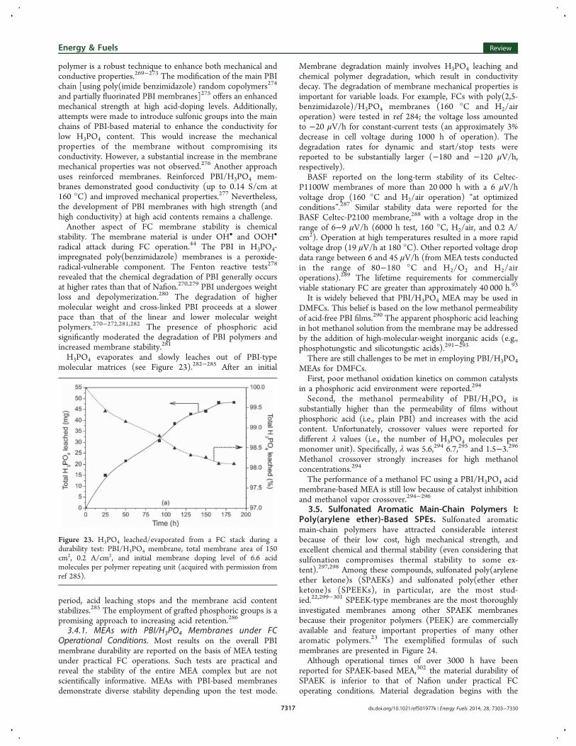
H3PO4 evaporates and slowly leaches out of PBI-typemolecular matrices (see Figure 23).282−285 After an initial
period, acid leaching stops and the membrane acid contentstabilizes.285 The employment of grafted phosphoric groups is apromising approach to increasing acid retention.286
3.4.1. MEAs with PBI/H3PO4 Membranes under FCOperational Conditions. Most results on the overall PBImembrane durability are reported on the basis of MEA testingunder practical FC operations. Such tests are practical andreveal the stability of the entire MEA complex but are notscientifically informative. MEAs with PBI-based membranesdemonstrate diverse stability depending upon the test mode.
Membrane degradation mainly involves H3PO4 leaching andchemical polymer degradation, which result in conductivitydecay. The degradation of membrane mechanical properties isimportant for variable loads. For example, FCs with poly(2,5-benzimidazole)/H3PO4 membranes (160 °C and H2/airoperation) were tested in ref 284; the voltage loss amountedto −20 μV/h for constant-current tests (an approximately 3%decrease in cell voltage during 1000 h of operation). Thedegradation rates for dynamic and start/stop tests werereported to be substantially larger (−180 and −120 μV/h,respectively).BASF reported on the long-term stability of its Celtec-
P1100W membranes of more than 20 000 h with a 6 μV/hvoltage drop (160 °C and H2/air operation) “at optimizedconditions”.287 Similar stability data were reported for theBASF Celtec-P2100 membrane,288 with a voltage drop in therange of 6−9 μV/h (6000 h test, 160 °C, H2/air, and 0.2 A/cm2). Operation at high temperatures resulted in a more rapidvoltage drop (19 μV/h at 180 °C). Other reported voltage dropdata range between 6 and 45 μV/h (from MEA tests conductedin the range of 80−180 °C and H2/O2 and H2/airoperations).289 The lifetime requirements for commerciallyviable stationary FC are greater than approximately 40 000 h.93
It is widely believed that PBI/H3PO4 MEA may be used inDMFCs. This belief is based on the low methanol permeabilityof acid-free PBI films.290 The apparent phosphoric acid leachingin hot methanol solution from the membrane may be addressedby the addition of high-molecular-weight inorganic acids (e.g.,phosphotungstic and silicotungstic acids).291−293
There are still challenges to be met in employing PBI/H3PO4MEAs for DMFCs.First, poor methanol oxidation kinetics on common catalysts
in a phosphoric acid environment were reported.294
Second, the methanol permeability of PBI/H3PO4 issubstantially higher than the permeability of films withoutphosphoric acid (i.e., plain PBI) and increases with the acidcontent. Unfortunately, crossover values were reported fordifferent λ values (i.e., the number of H3PO4 molecules permonomer unit). Specifically, λ was 5.6,294 6.7,295 and 1.5−3.296Methanol crossover strongly increases for high methanolconcentrations.294
The performance of a methanol FC using a PBI/H3PO4 acidmembrane-based MEA is still low because of catalyst inhibitionand methanol vapor crossover.294−296
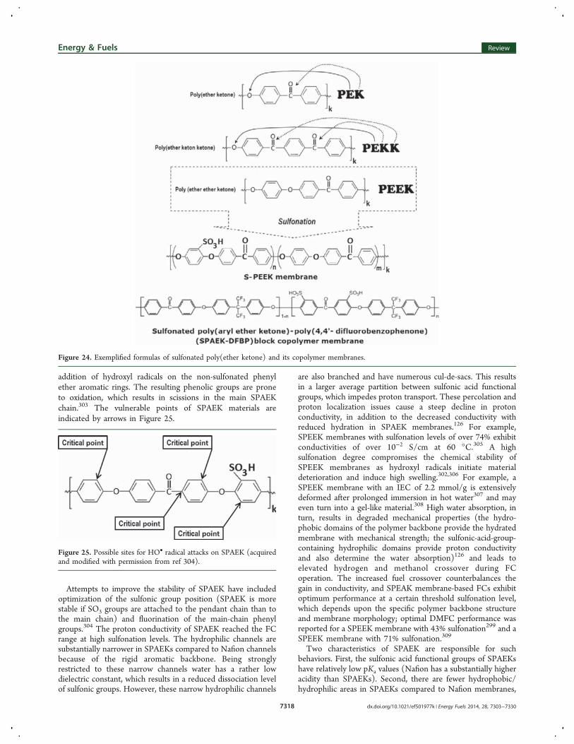
3.5. Sulfonated Aromatic Main-Chain Polymers I:Poly(arylene ether)-Based SPEs. Sulfonated aromaticmain-chain polymers have attracted considerable interestbecause of their low cost, high mechanical strength, andexcellent chemical and thermal stability (even considering thatsulfonation compromises thermal stability to some ex-tent).297,298 Among these compounds, sulfonated poly(aryleneether ketone)s (SPAEKs) and sulfonated poly(ether etherketone)s (SPEEKs), in particular, are the most stud-ied.22,299−301 SPEEK-type membranes are the most thoroughlyinvestigated membranes among other SPAEK membranesbecause their progenitor polymers (PEEK) are commerciallyavailable and feature important properties of many otheraromatic polymers.23 The exemplified formulas of suchmembranes are presented in Figure 24.Although operational times of over 3000 h have been
reported for SPAEK-based MEA,302 the material durability ofSPAEK is inferior to that of Nafion under practical FCoperating conditions. Material degradation begins with the
Figure 23. H3PO4 leached/evaporated from a FC stack during adurability test: PBI/H3PO4 membrane, total membrane area of 150cm2, 0.2 A/cm2, and initial membrane doping level of 6.6 acidmolecules per polymer repeating unit (acquired with permission fromref 285).
Energy & Fuels Review
dx.doi.org/10.1021/ef501977k | Energy Fuels 2014, 28, 7303−73307317
addition of hydroxyl radicals on the non-sulfonated phenylether aromatic rings. The resulting phenolic groups are proneto oxidation, which results in scissions in the main SPAEKchain.303 The vulnerable points of SPAEK materials areindicated by arrows in Figure 25.
Attempts to improve the stability of SPAEK have includedoptimization of the sulfonic group position (SPAEK is morestable if SO3 groups are attached to the pendant chain than tothe main chain) and fluorination of the main-chain phenylgroups.304 The proton conductivity of SPAEK reached the FCrange at high sulfonation levels. The hydrophilic channels aresubstantially narrower in SPAEKs compared to Nafion channelsbecause of the rigid aromatic backbone. Being stronglyrestricted to these narrow channels water has a rather lowdielectric constant, which results in a reduced dissociation levelof sulfonic groups. However, these narrow hydrophilic channels
are also branched and have numerous cul-de-sacs. This resultsin a larger average partition between sulfonic acid functionalgroups, which impedes proton transport. These percolation andproton localization issues cause a steep decline in protonconductivity, in addition to the decreased conductivity withreduced hydration in SPAEK membranes.126 For example,SPEEK membranes with sulfonation levels of over 74% exhibitconductivities of over 10−2 S/cm at 60 °C.305 A highsulfonation degree compromises the chemical stability ofSPEEK membranes as hydroxyl radicals initiate materialdeterioration and induce high swelling.302,306 For example, aSPEEK membrane with an IEC of 2.2 mmol/g is extensivelydeformed after prolonged immersion in hot water307 and mayeven turn into a gel-like material.308 High water absorption, inturn, results in degraded mechanical properties (the hydro-phobic domains of the polymer backbone provide the hydratedmembrane with mechanical strength; the sulfonic-acid-group-containing hydrophilic domains provide proton conductivityand also determine the water absorption)126 and leads toelevated hydrogen and methanol crossover during FCoperation. The increased fuel crossover counterbalances thegain in conductivity, and SPEAK membrane-based FCs exhibitoptimum performance at a certain threshold sulfonation level,which depends upon the specific polymer backbone structureand membrane morphology; optimal DMFC performance wasreported for a SPEEK membrane with 43% sulfonation299 and aSPEEK membrane with 71% sulfonation.309
Two characteristics of SPAEK are responsible for suchbehaviors. First, the sulfonic acid functional groups of SPAEKshave relatively low pKa values (Nafion has a substantially higheracidity than SPAEKs). Second, there are fewer hydrophobic/hydrophilic areas in SPAEKs compared to Nafion membranes,
Figure 24. Exemplified formulas of sulfonated poly(ether ketone) and its copolymer membranes.
Figure 25. Possible sites for HO• radical attacks on SPAEK (acquiredand modified with permission from ref 304).
Energy & Fuels Review
dx.doi.org/10.1021/ef501977k | Energy Fuels 2014, 28, 7303−73307318
which results in a slimmer and poorly connected water-fillednetwork; the latter suggests larger separations between thesulfonic groups (i.e., less acidic than in Nafion case).126,310−313
Currently, SPAEK membranes with fair conductivity (up to0.048 S/cm at room temperature) are being devel-oped.299,306,314 SPEEK membranes with conductivities over0.1 S/cm were also reported.311
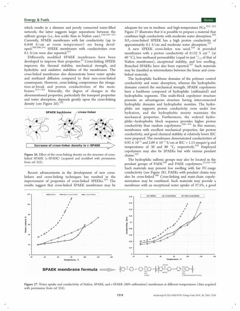
Differently modified SPAEK membranes have beendeveloped to improve their properties.23 Cross-linking SPEEKimproves the thermal stability, mechanical strength, andhydrolytic and oxidative stabilities of the membranes. Thecross-linked membranes also demonstrate lower water uptakeand methanol diffusion compared to their non-cross-linkedcounterparts. However, cross-linking compromises the elonga-tion-at-break and proton conductivities of the mem-branes.315−321 Naturally, the degree of changes in theaforementioned properties, particularly the transport propertiesand water absorption, depends greatly upon the cross-linkingdensity (see Figure 26).322
Recent advancements in the development of new cross-linkers and cross-linking techniques has resulted in theimprovement of properties of cross-linked SPEEKs.319 Theresults suggest that cross-linked SPAEK membranes may be
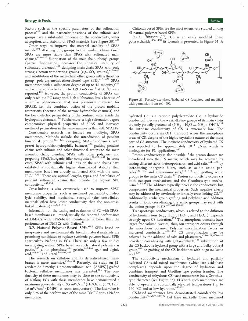
adequate for use in medium- and high-temperature FCs.323−325
Figure 27 illustrates that it is possible to prepare a material thatcombines high conductivity with moderate water absorption.324
SO2-cross-linked SPEEK has a high proton conductivity ofapproximately 0.1 S/cm and moderate water absorption.317
A new SPEEK cross-linker was used.326 It providedmembranes with a proton conductivity of 0.122 S cm−1 (at60 °C), low methanol permeability (equal to just 1/12 of that ofNafion membranes), exceptional stability, and low swelling.Branched SPAEKs have also been reported.327 Such materialsmay be classified as intermediates between the linear and cross-linked materials.The hydrophilic backbone domains of the polymer control
conductivity and water absorption, whereas the hydrophobicdomains control the mechanical strength. SPAEK copolymershave a backbone composed of hydrophilic (sulfonated) andhydrophobic segments. This multi-block copolymer structurepresents an advantageous structure having interconnectedhydrophilic domains and hydrophobic moieties. The hydro-philic net supports proton conductivity even under lowhydration, and the hydrophobic moiety maintains themechanical properties. Furthermore, the ordered hydro-philic−hydrophobic block sequence provides higher protonconductivity than random copolymers.328−331 In this manner,membranes with excellent mechanical properties, fair protonconductivity, and good chemical stability at relatively lower IECwere prepared. The membranes demonstrated conductivities of0.92 × 10−2 and 2.09 × 10⁻² S/cm at IEC = 1.13 mequiv/g andtemperatures of 30 and 80 °C, respectively.332 Employedcopolymers may also be SPAEKs but with various pendantchains.333
The hydrophilic sulfonic groups may also be located in thependant groups of PAEK334 and PAEK copolymers.23,335−339
Such materials may present low swelling with fair FC-rangeconductivity (see Figure 28). PAEKs with pendant chains mayalso be cross-linked.340 Cross-linking and main-chain copoly-merization may be combined. Such materials may provide amembrane with an exceptional water uptake of 37.5%, a good
Figure 26. Effect of the cross-linking density on the structure of cross-linked SPAEK (c-SPAEK) (acquired and modified with permissionfrom ref 322).
Figure 27. Water uptake and conductivity of Nafion, SPAEK, and c-SPAEK (80% sulfonation) membranes at different temperatures (data acquiredwith permission from ref 324).
Energy & Fuels Review
dx.doi.org/10.1021/ef501977k | Energy Fuels 2014, 28, 7303−73307319
proton conductivity of 0.091 S/cm, and a methanol selectivityβ, which is approximately 30 times larger than the β ofNafion.322
Other common ways to improve the properties of SPAEKmembranes is to mix SPAEK material with other polymers orto incorporate inorganic fillers into the membrane. Recently,several good reviews on such composite SPAEK membraneswere published.38,82,126,315 SPAEK has been combined withpolybenzimidazole,341,342 poly(ether sulfone),343−345 sulfo-nated/silylated polyphenylsulfone,346 sulfonated cyclodex-trin,347 poly(vinylidene fluoride)348−351 (a model DMFC withsuch a membrane demonstrated a low decay of maximumpower density of approximately 5.7 × 10⁻⁹ W/cm2 per hour fora cell operating up to 1300 h),352 poly(vinylidene fluoride-co-hexafluoro propylene),351 phosphonated polysulfone,353 3-aminopropyltriethoxysilane,354 sulfonated phenolphthaleinpoly(ether sulfone),355 acrylic acid-co-4-vinylimidazole,356
phenoxy resin,357 polyimide,358 poly(ether imide),359 poly-pyrrole,360 Nafion (SPAEK and Nafion are incompatible;SPAEK demonstrates a “flaky” sediment inside the Nafionmatrix),361 covalent-type Nafion introduction into SPAEKfollowed by cross-linking,362 polyacrylonitrile,363 epoxy res-ins,364,365 polystyrenesulfonic acid,366 sulfonated and/orsilylated polyphenylsulfone,367 and poly(vinyl alcohol).368
Although the blended membranes are mainly linear, theblended membranes may be prepared by cross-linking themixture of linear polymers (SPAEK and the additive), whichresults in interpenetrating polymer nets.369−371
Composite, multi-layer SPAEK membranes have also beendeveloped to account for the apparent asymmetry in FCs; i.e.,fuel diffusion occurs on the cell anode side, whereas peroxide-related issues (the major source of the membrane degradation)occur at the cathode side. The idea of a multi-layer membraneis that the anode protective layer would be prepared from amaterial with a low fuel permeability and, thus, may beextremely thin and will not compromise the overall membraneconductivity and mechanical properties. The cathode layerwould be prepared from a thin material that is stable againstperoxide.372
It was reported that thin (10 mcm or thinner) layers of across-linked chitosan increased the membrane methanolselectivity β by 5-fold while not significantly decreasing themembrane conductivity.373 A thin layer of poly(vinyl alcohol)was also tested as a barrier against methanol diffusion.374 TheSPAEK may be used as a thin layer to block methanol diffusionin the Nafion/SPAEK/Nafion structure.375
Preparation of SPAEK/inorganic filler composites is acommon technique to improve proton conductivity, waterretention (particularly at high temperatures), and mechanicalproperties.66
The combination of SPAEK with solid heteropolyacids is apromising way to improve the membrane proton conductivityand hydrolytic stability and to diminish methanol perme-ability.376 Such heteropolyacids and their salts, e.g., H3PW12O40,H4SiW12O40, H3PMo12O40,
H3SiW12O40/montmorillonite, were reported.379 CompositeSPAEK-based membranes with incorporated small cross-linkedpolycarboxylic acid spheres (150 nm in diameter)380 andpolymeric phosphonic acid sub-micrometer spheres381 werealso reported.The combination of SPAEK with non-acid inorganic
materials is another promising method to improve SPAEK-based membranes.66,382 SPAEK was combined with zirconiumhydrogen phosphate, which diminished the methanol perme-ability and water uptake without compromising mechanicalstability; however, proton conductivity decreased.66,383 SPAEKwas also combined with zirconium phosphate sulfophenylen-phosphonates; these membranes demonstrated a high con-ductivity (up to 0.1 S/cm at 80 °C).66,384,385 The SPAEKcomposite membranes with surface-modified SiO2,
382,386−388
ZrO2,389,390 TiO2 and TiO2 with a modified surface,389−393 and
Zr/Ti/phosphate394 and SPAEK composite membranes withmethanesulfonic-acid-modified zeolite 4A,395 Fe3O4,
396 andboron orthophosphate (BPO4)
397,398 were also reported.
Figure 28. Arrhenius plot of proton conductivity (the membranes are immersed in water) and water volume fraction versus temperature for PAEKwith flexible tetrasulfonated pendant chains.338
Energy & Fuels Review
dx.doi.org/10.1021/ef501977k | Energy Fuels 2014, 28, 7303−73307320
SPAEK-based membranes exhibit inferior performancecompared to current Nafion membranes in H2/air FCs becauseof their inadequate proton conductivity and lower membranestability. Current efforts on these membranes are focused onimproving the conductivity, maintaining a low water uptake,and improving the membrane lifetime. SPAEK membranesoften exhibit significantly higher methanol selectivity comparedto Nafion membranes.298,300−302,399
3.6. Sulfonated Aromatic Main-Chain Polymers II:Polysulfone-, Polysulfone-Ether-, and Polyphenylsul-fone-Based SPEs. Sulfonated poly(aryl sulfones) (SPAS),such as polysulfones (SPSUs), polysulfone ethers (SPSEs), andpolyphenylsulfones (SPPSUs), are sulfonated aromatic main-chain polymers, similar to SPAEKs. The first preparation ofSPAS membranes was reported in ref 400, and the first
chemical power source (alkaline Zn/redox battery) wasreported in ref 401. The precursor polymers are commerciallyavailable and inexpensive as well as thermally and chemicallystable; thus, the sulfonated modifications of these materials arealso expected to retain these features. These polymers are fullyamorphous, and therefore, their mechanical properties dependupon chemical modification,402,403 as opposed to SPAEKs. Theexemplified formulas of PPSUs, SPPSUs, and SPSEs arepresented in Figure 29.Materials with such properties are considered potentially
viable for SPE applications.404,405 As in the case of SPAEK-based materials, SPAS-based materials demonstrated lowerstability against superoxides than Nafion.406 The materialdegradation mechanism and critical points of the SPASmolecule are similar to those of SPAEK (see Figure 25).304
Figure 29. Exemplified formulas of sulfonated polysulfone and sulfonated polyphenylsulfone SPEs (acquired and modified with permission from ref402).
Figure 30. Influence of Fenton’s reagent on remaining IEC as a function of the immersion time for the different sulfonated membranes (acquiredand modified with permission from ref 407).
Energy & Fuels Review
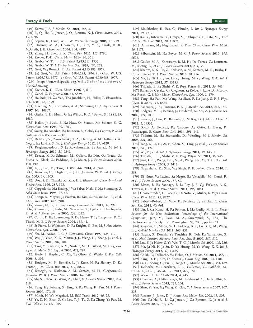
dx.doi.org/10.1021/ef501977k | Energy Fuels 2014, 28, 7303−73307321
Factors such as the specific parameters of the sulfonationprocess422 and the particular positions of the sulfonic acidgroups have a substantial influence on the conductivity, waterabsorption, and stability of SPAS materials (see Figure 30).407
Other ways to improve the material stability of SPASinclude304 attaching SO3 groups to the pendant chains (suchSPAS are more stable than SPAS with sulfonated mainchains),408−410 fluorination of the main-chain phenyl groups(partial fluorination increases the chemical stability ofsulfonated arylenes),411 designing main-chain SPAS with onlystrong electron-withdrawing groups (e.g., SO2 groups),
412−415
and substitution of the main-chain ether group with a thioethergroup [poly(arylenethioethersulfone)-type SPE].416−420 SPASmembranes with a sulfonation degree of up to 4.1 mequiv/g421
and with a conductivity up to 159.0 mS cm−1 at 80 °C werereported.422 However, the proton conductivity of SPAS canonly reach the FC range with high sulfonation levels because ofa similar phenomenon that was previously discussed forSPAEK, i.e., the combined action of the proton mobilityrestrictions (because of the narrow hydrophilic channels) andthe low dielectric permeability of the confined water inside thehydrophilic channels.126 Furthermore, a high sulfonation degreecompromises physical properties of SPAS and increasesmethanol permeation in the same manner as that with SPAEKs.Considerable research has focused on modifying SPAS
membranes. Methods include the introduction of pendantfunctional groups,423−425 designing SPAS-co-polymers withpreset hydrophobic/hydrophilic balances,426 grafting pendantchains with sulfonic and other functional groups to the mainaromatic chain, blending SPAS with other polymers, andpreparing SPAS/inorganic filler composites.82,427−431 In somecases, SPAS with sulfonic acid units on the side chains haveexhibited a substantially higher dimensional stability thanmembranes based on directly sulfonated SPE with the sameIEC.429,432 There are optimal lengths, types, and flexibilities ofpendant sulfonated chains that provide the highest SPEconductivity.432,433
Cross-linking is also extensively used to improve SPSUmembrane properties, such as methanol permeability, hydro-lytic stability, and mechanical strength (the cross-linkedmaterials often have lower conductivity than the non-cross-linked materials).319,434−440
Information on the testing and evaluation of FC with SPAS-based membranes is limited; usually the reported performanceof DMFCs with SPAS-based membranes is lower than theperformance of DMFCs with Nafion.441
3.7. Natural Polymer-Based SPEs.442 SPEs based oninexpensive and environmentally friendly natural materials arepromising candidates to replace synthetic polymer-based SPEs(particularly Nafion) in FCs. There are only a few studiesinvestigating natural SPEs based on such natural polymers aspectin,443 chitin phosphate,444 gelatin,445,446 agar and alginicacid,444,447 and uracil.444,448,449
The research on cellulose and its derivative-based mem-branes is more extensive.450−454 Recently, the study on [2-acrylamido-2-methyl-1-propanesulfonic acid (AMPS)]-graftedbacterial cellulose membranes was presented.455 The con-ductivity of these membranes may be close to the conductivityof Nafion; FCs with these membranes have demonstrated amaximum power density of 95 mW/cm2 (H2/O2, at 50 °C) and16 mW/cm2 (DMFC, at room temperature). The last value isonly 35% of the performance of the same DMFC with a Nafionmembrane.
Chitosan-based SPEs are the most extensively studied amongall natural polymer-based SPEs.
3.7.1. Chitosan (CS). CS is an easily modified linearpolysaccharide;456−458 its formula is presented in Figure 31. A
hydrated CS is a cationic polyelectrolyte (i.e., a hydroxideconductor). Because the weak alkaline groups of its main chainare only partially protonated (NH2 + H2O ⇆ NH3 + OH−),459
the intrinsic conductivity of CS is extremely low. Theconductivity occurs via OH− transport across the amorphousareas of CS, despite of the highly crystalline nature of the mostpart of CS structure. The intrinsic conductivity of hydrated CSwas reported to be approximately 10−4 S/cm, which isinadequate for FC applications.460
Proton conductivity is also possible if the proton donors areintroduced into the CS matrix, which may be achieved bymixing different acids, heteropolyacids, and acid salts,461−468 byintroducing inorganic fillers, such as acidic oxide par-ticles469−472 and ammonium salts,473−476 and grafting acidicgroups to the main CS chain.477 Proton conductivity occurs viaboth transport mechanisms and the Grotthuss-type mecha-nism.478,479 The additives typically increase the conductivity butcompromise the mechanical properties. Such negative effectsmay be addressed by covalently or ionically cross-linking CS.480
Additionally, acidic group grafting and polybasic acid additionresults in ionic cross-linking; the acidic groups may react withthe amino groups in CS.466,464,478,481
Transport-type conductivity, which is related to the diffusionof hydronium ions (e.g., H3O
+, H5O2+, and H9O4
+), dependsstrongly upon CS hydration.479 The amorphous domains havelarger free volume cavities; thus, ion transport occurs throughthe amorphous polymer. Polymer amorphization favors anincreased conductivity.482−484 CS amorphization may beachieved by the addition of salts and plasticizers,473−475,485−487
covalent cross-linking with glutaraldehyde,488 substitution ofthe CS backbone hydroxyl group with a large and bulky butyrylgroup,489 or grafting of the CS backbones with oligo-D,L-lacticacid.490
The conductivity mechanism of hydrated and partiallyhydrated CS−acid mixed membranes (which are acid−basecomplexes) depends upon the degree of hydration andcombines transport and Grotthus-type proton transfer. Theconductivity of anhydrous CS−acid membranes has a Grotthus-type character (see Figure 32). FCs with such membranes areable to operate at substantially elevated temperatures (up to160 °C) and at low hydration.448,491
CS-based membranes have demonstrated considerably lowconductivity457,479,480,492 but have markedly lower methanol
Figure 31. Partially acetylated/hydrated CS (acquired and modifiedwith permission from ref 460).
Energy & Fuels Review
dx.doi.org/10.1021/ef501977k | Energy Fuels 2014, 28, 7303−73307322
permeabilities than Nafion.457,466 The latter characteristicsuggests the possibility of using relatively thin CS membranesfor DMFC, which may counter the low conductivity of the CSmembranes.Information on FCs using CS-based membranes is scarce.
The model H2/O2 FC with a composite CS membranedemonstrated a maximum power density of 16 mW/cm2 at 75°C. It was suggested that the reported poor performance of thiscell might be due to a problematic MEA fabrication.493 ADMFC using an acid-cross-linked CS membrane demonstratedmaximum power densities of 27.4 and 42.4 mW/cm2 at roomtemperature (for CS membranes with different degrees ofdeacetylation), whereas the same DMFC using a Nafion-117-based MEA demonstrated a maximum power density of 74.7mW/cm2.494,495 The DMFC that used a membrane composedof CS mixed with phosphotungstic acid and montmorillonitedemonstrated a maximal power density of 60.7 mW/cm2 andan operation stability for more than 100 h at 70 °C. The samemodel DMFC using a Nafion 117 membrane demonstrated amaximal power density of 47 mW/cm2.
4. OVERVIEW AND FUTURE PERSPECTIVEThe emerging FC market is a strong driving force, pushing thescientific community to develop inexpensive and high-perform-ing membrane materials. The cost of a FC system should bereduced by 40%; currently, the cost is approximately $50/kW,whereas the goal of the U.S. Department of Energy (DOE) is$30/kW.496 However, the costs for the manufacturing plantsaccount for more than 50% of the total system cost. This costcomponent has not been significantly reduced in the past fewyears.497 The membrane contributes the largest factor of theoverall FC cost (see Figure 6). The cost reduction of thecatalyst (the other essential FC cost component) is possibleonly through a reduction in Pt content. However, in the pastfew years, the amount of Pt in FCs has remained relativelyconstant.498 The one major approach to reducing the cost ofFCs, which is crucial for the widespread acceptance of FCs asthe primary energy source for various practical applications, isto reduce the membrane cost.Considering that Nafion prices have not changed signifi-
cantly from 2006 to 2011499 (even considering inflation),500
research and development will be focused on non-Nafion-typematerials. DMFCs are the most promising FCs for trans-portation and portable electronic applications because of majorconcerns related to hydrogen storage (hydrogen has a highgravimetric specific energy but a low volumetric energydensity). This has motivated the development of membranes
having a high methanol selectivity, β. Although Nafionmembranes have a low β value, they may be improved bydeveloping proper Nafion/inorganic and Nafion/polymercomposite materials. In addition, many alternative ionomershave a substantially higher β than Nafion. Another issueconcerns the limited ability of Nafion to operate at elevatedtemperatures. This drawback may be addressed by resorting toNafion/inorganic and Nafion/polymer composite membranes.Furthermore, many alternative ionomers have a significantlyhigher temperature operation range than Nafion.Most alternative membranes are ranked below Nafion
membranes over an entire set of important properties. It maybe worthwhile to compromise on conductivity and developalternative membranes that are superior to Nafion in terms oftemperature stability, operability over a wider range ofconditions (e. g., lower humidity) with reduced overall swelling,lower fuel crossover, and particularly, lower cost. There aregood reasons to believe that the scientific community is capableof overcoming the problems currently associated with PEMmembranes. Commercially viable FC membranes are “justaround the corner”.
■ ACKNOWLEDGMENTSSupport for this work was provided by the Grand TechnionEnergy Program (GTEP) and the Leona and Harry B.Helmsley Charitable Trust.
■ REFERENCES(1) Grove, W. R. Philos. Mag. J. Sci. 1842, 21, 417 https://archive.org/details/londonedinburghp21lond.(2) Schonbein, C. F. Ann. Phys. 1849, 154, 289.(3) Ostwald, W. Z. Elektrotech. Elektrochem. 1894, 1, 122.(4) Mond, L.; Langer, C. Proc. R. Soc. London 1889, 46, 296.(5) Wright, C. R. A.; Thompson, C. Proc. R. Soc. London 1889, 46,372.(6) Jacoues, W.W. U.S. Patent 555,511, 1896.(7) Baur, E.; Tobler, J. Z. Elektrochem. Angew. Phys. Chem. 1933, 39,169.(8) Bacon, F. T. Electrochim. Acta 1969, 14, 569.(9) Thomas, B. F.; Wiliam, J. P. U.S. Patent 2,716,670, 1955.(10) Fuel Cell Today. The Fuel Cell Industry Review; Fuel Cell Today:London, U.K., 2012; www.fuelcelltoday.com, http://www.fuelcelltoday.com/media/1713685/fct_review_2012.pdf (accessedJune 14, 2014).(11) http://www1.eere.energy.gov/hydrogenandfuelcells/fuelcells/pdfs/fc_comparison_chart.pdf.(12) http://www.ballard.com/be_informed/fuel_cell_technology/how_the_technology_works.(13) http://wikieducator.org/File:Fuel_Cell.png.(14) Spendelow, J.; Marcinkoski, J. DOE Fuel Cell Technologies OfficeRecord 13012: Fuel Cell System Cost2013; U.S. Department ofEnergy (DOE): Washington, D.C., 2013; http://www.hydrogen.energy.gov/pdfs/13012_fuel_cell_system_cost_2013.pdf (accessedJune 14, 2014).(15) Smitha, B.; Sridhar, S.; Khan, A. A. J. Membr. Sci. 2005, 259, 10.(16) Roziere, J.; Jones, D. J. Annu. Rev. Mater. Res. 2003, 33, 503.(17) Iojoiu, C.; Chabert, F.; Marechal, M.; Kissi, N. El.; Guindet, J.;Sanchez, J.-Y. J. Power Sources 2006, 153, 198.(18) Deluca, N. W.; Elabd, Y. A. J. Polym. Sci. 2006, 44, 2201.
Figure 32. Anhydrous proton-conducting mechanism of CS/mix;arrows denote proton transfer (acquired and modified with permissionfrom ref 491).
Energy & Fuels Review
dx.doi.org/10.1021/ef501977k | Energy Fuels 2014, 28, 7303−73307323
(19) Kerres, J. A. J. Membr. Sci. 2001, 185, 3.(20) Li, Q.; He, R.; Jensen, J. O.; Bjerrum, N. J. Chem. Mater. 2003,15, 4896.(21) Sopian, K.; Daud, W. R. W. Renewable Energy 2006, 31, 719.(22) Hickner, M. A.; Ghassemi, H.; Kim, Y. S.; Einsla, B. R.;McGrath, J. E. Chem. Rev. 2004, 104, 4587.(23) Zhang, H.; Shen, P. K. Chem. Rev. 2012, 112, 2780.(24) Kreuer, K.-D. Chem. Mater. 2014, 26, 361.(25) Grubb, W. T., Jr. U.S. Patent 2,913,511, 1955.(26) Grubb, W. T. J. Electrochem. Soc. 1959, 106, 275.(27) Grot, W.; Resnick, P. U.S. Patent 4,113,585, 1978.(28) (a) Grot, W. U.S. Patent 3,969,285, 1976. (b) Grot, W. U.S.Patent 4,026,783, 1977. (c) Grot, W. U.S. Patent 4,030,988, 1977.(29) http://en.wikipedia .org/wiki/Nafion#mediaviewer/File:Nafion2.svg.(30) Kreuer, K.-D. Chem. Mater. 1996, 8, 610.(31) Gebel, G. Polymer 2000, 41, 5829.(32) Haubold, H.-G.; Vad, Th.; Jungbluth, H.; Hiller, P. Electrochim.Acta 2001, 46, 1559.(33) Eikerling, M.; Kornyshev, A. A.; Stimming, U. J. Phys. Chem. B1997, 101, 10807.(34) Gierke, T. D.; Munn, G. E.; Wilson, F. C. J. Polym. Sci. 1981, 19,1687.(35) Halim, J.; Buchi, F. N.; Haas, O.; Stamm, M.; Scherer, G. G.Electrochim. Acta 1994, 39, 1303.(36) Souzy, R.; Ameduri, B.; Boutevin, B.; Gebel, G.; Capron, P. SolidState Ionics 2005, 176, 2839.(37) Di Noto, V.; Zawodzinski, T. A.; Herring, A. M.; Giffin, G. A.;Negro, E.; Lavina, S. Int. J. Hydrogen Energy 2012, 37, 6120.(38) Peighambardoust, S. J.; Rowshanzamir, S.; Amjadi, M. Int. J.Hydrogen Energy 2010, 35, 9349.(39) Kreuer, K.-D.; Schuster, M.; Obliers, B.; Diat, O.; Traub, U.;Fuchs, A.; Klock, U.; Paddison, S. J.; Maier, J. J. Power Sources 2008,178, 499.(40) Li, J.; Pan, M.; Tang, H. RSC Adv. 2014, 4, 3944.(41) Beuscher, U.; Cleghorn, S. J. C.; Johnson, W. B. Int. J. EnergyRes. 2005, 29, 1103.(42) Uosaki, K.; Okazaki, K.; Kita, H. J. Electroanal. Chem. InterfacialElectrochem. 1990, 287, 163.(43) Cappadonia, M.; Erning, J. W.; Saberi Niaki, S. M.; Stimming, U.Solid State Ionics 1995, 77, 65.(44) Borup, R.; Meyers, J.; Pivovar, B.; Kim, S.; Mukundan, R.; et al.Chem. Rev. 2007, 107, 3904.(45) Zamel, N.; Li, X. Prog. Energy Combust. Sci. 2011, 37, 292.(46) Kinumoto, T.; Inaba, M.; Nakayama, Y.; Ogata, K.; Umebayashi,R.; et al. J. Power Sources 2006, 158, 1222.(47) Curtin, D. E.; Lousenberg, R. D.; Henry, T. J.; Tangeman, P. C.;Tisack, M. E. J. Power Sources 2004, 131, 41.(48) St-Pierre, J.; Wilkinson, D. P.; Knights, S.; Bos, M. J. New Mater.Electrochem. Syst. 2000, 3, 99.(49) Shi, M.; Anson, F. C. J. Electroanal. Chem. 1997, 425, 117.(50) Wu, J.; Yuan, X. Z.; Martin, J. J.; Wang, H.; Zhang, J.; et al. J.Power Sources 2008, 184, 104.(51) Tang, Y.; Karlsson, A. M.; Santare, M. H.; Gilbert, M.; Cleghorn,S.; et al. Mater. Sci. Eng., A 2006, 425, 297.(52) Healy, J.; Hayden, C.; Xie, T.; Olson, K.; Waldo, R. Fuel Cells2005, 5, 302.(53) Rodgers, M. P.; Bonville, L. J.; Kunz, H. R.; Slattery, D. K.;Fenton, J. M. Chem. Rev. 2012, 112, 6075.(54) Kusoglu, A.; Karlsson, A. M.; Santare, M. H.; Cleghorn, S.;Johnson, W. B. J. Power Sources 2006, 161, 987.(55) Shi, S.; Chen, G.; Wang, Z.; Chen, X. J. Power Sources 2013, 238,318.(56) Tang, H.; Peikang, S.; Jiang, S. P.; Wang, F.; Pan, M. J. PowerSources 2007, 170, 85.(57) Mindt, H.-W.; Megahed, M. ECS Trans. 2012, 40, 25.(58) Ye, D. H.; Zhan, Z. G.; Lee, Y. J.; Tu, Z. K.; Zhang, Y.; Pan, M.Fuel Cells 2013, 13, 1205.
(59) Moukheiber, E.; Bas, C.; Flandin, L. Int. J. Hydrogen Energy2014, 39, 2717.(60) Kai, Y.; Kitayama, Y.; Omiya, M.; Uchiyama, T.; Kato, M. J. FuelCell Sci. Technol. 2013, 10, 21007.(61) Ozmaiana, M.; Naghdabadi, R. Phys. Chem. Chem. Phys. 2014,16, 3173.(62) Silberstein, M. N.; Boyce, M. C. J. Power Sources 2010, 195,5692.(63) Goulet, M.-A.; Khorasany, R. M. H.; De Torres, C.; Lauritzen,M.; Kjeang, E.; et al. J. Power Sources 2013, 234, 38.(64) Khattra, N. S.; Lu, Z.; Karlsson, A. M.; Santare, M. H.; Busby, F.C.; Schmiedel, T. J. Power Sources 2013, 28, 256.(65) Ma, J.; Ni, H.-J.; Su, D.-Y.; Huang, M.-Y.; Wang, X.-X. Int. J.Hydrogen Energy 2012, 37, 13185.(66) Tripathi, B. P.; Shahi, V. K. Prog. Polym. Sci. 2011, 36, 945.(67) Bahar, B.; Cavalca, C.; Cleghorn, S.; Kolde, J.; Lane, D.; Murthy,M.; Rusch, G. J. New Mater. Electrochem. Syst. 1999, 2, 179.(68) Tang, H.; Pan, M.; Wang, F.; Shen, P. K.; Jiang, S. P. J. Phys.Chem. B 2007, 111, 8684.(69) Ballengee, J. B.; Pintauro, P. N. J. Membr. Sci. 2013, 442, 187.(70) Rodgers, M. P.; Berring, J.; Holdcroft, S.; Shi, Z. J. Membr. Sci.2008, 321, 100.(71) Saleem, J.; Gao, P.; Barforda, J.; McKay, G. J. Mater. Chem. A2013, 1, 14335.(72) Sacca, A.; Pedicini, R.; Carbone, A.; Gatto, I.; Fracas, P.;Passalacqua, E. Chem. Phys. Lett. 2014, 591, 149.(73) Yildirim, M. H.; Stamatialis, D.; Wessling, M. J. Membr. Sci.2008, 321, 364.(74) Yang, L.; Li, H.; Ai, F.; Chen, X.; Tang, J.; et al. J. Power Sources2013, 243, 392.(75) Wu, B.; et al. Int. J. Hydrogen Energy 2014, 39, 14381.(76) Tripathi, B. P.; Shahi, V. K. Prog. Polym. Sci. 2011, 36, 945.(77) Jung, G.-B.; Weng, F.-B.; Su, A.; Wang, J.-S.; Yu, T. L.; et al. Int.J. Hydrogen Energy 2008, 3, 2413.(78) Nagarale, R. K.; Shin, W.; Singh, P. K. Polym. Chem. 2010, 1,388.(79) Di Noto, V.; Lavina, S.; Negro, E.; Vittadello, M.; Conti, F.;et al. J. Power Sources 2009, 187, 57.(80) Matos, B. R.; Santiago, E. I.; Rey, J. F. Q.; Ferlauto, A. S.;Traversa, E.; et al. J. Power Sources 2011, 196, 1061.(81) Ghassemzadeh, L.; Pace, G.; Di Noto, V.; Muller, K. Phys. Chem.Chem. Phys. 2011, 13, 9327.(82) Laberty-Robert, C.; Valle, K.; Pereirab, F.; Sanchez, C. Chem.Soc. Rev. 2011, 40, 961.(83) Lin, J. C.; Kuntz, H. R.; Fenton, J. M.; Cutlip, M. B. In PowerSources for the New Millenium: Proceedings of the InternationalSymposium; Jain, M., Ryan, M. A., Surampudi, S., Eds.; TheElectrochemial Society, Inc.: Pennington, NJ, 2001; pp 48−63.(84) Klaysom, C.; Moon, S.-H.; Ladewig, B. P.; Lu, G. Q. M.; Wang,L. J. Colloid Interface Sci. 2011, 363, 431.(85) Nagata, S.; Konishi, Y.; Tsuchiya, B.; Toh, K.; Yamamoto, S.;et al. Nucl. Instrum. Methods Phys. Res., Sect. B 2007, 257, 519.(86) Lue, S. J.; Hsiaw, S.-Y.; Wei, T.-C. J. Membr. Sci. 2007, 305, 226.(87) Ma, J.; Ni, H.-J.; Su, D.-Y.; Huang, M.-Y.; Wang, X.-X. Int. J.Hydrogen Energy 2012, 37, 13185.(88) Chikh, L.; Delhorbe, V.; Fichet, O. J. Membr. Sci. 2011, 368, 1.(89) Kang, D. H.; Kim, D. Korean J. Chem. Eng. 2007, 24, 1101.(90) Li, T.; Zhong, G.; Fu, R.; Yang, Y. J. Membr. Sci. 2010, 354, 189.(91) Delhorbe, V.; Reijerkerk, S. R.; Cailleteau, C.; Bathfield, M.;Chikh, L.; et al. J. Membr. Sci. 2013, 429, 168.(92) Wieser, C. Fuel Cells 2004, 4, 245.(93) Chandan, A.; Hattenberger, M.; El-kharouf, A.; Du, S.; Dhir, A.;et al. J. Power Sources 2013, 231, 264.(94) Shao, Y.; Yin, G.; Wang, Z.; Gao, Y. J. Power Sources 2007, 167,235.(95) Roziere, J.; Jones, D. J. Annu. Rev. Mater. Res. 2003, 33, 503.(96) Pan, C.; He, R.; Li, Q.; Jensen, J. O.; Bjerrum, N. J.; et al. J.Power Sources 2005, 145, 392.
Energy & Fuels Review
dx.doi.org/10.1021/ef501977k | Energy Fuels 2014, 28, 7303−73307324
(97) Park, C. H.; Lee, C. H.; Guiver, M. D.; Lee, Y. M. Prog. Polym.Sci. 2011, 36, 1443.(98) Voel, C.; Haack, J. M. Desalination 2014, 342, 156.(99) Peckham, T. J.; Holdcroft, S. Adv. Mater. 2010, 22, 4667.(100) Basura, V. I.; Chuy, C.; Beattie, P. D.; Holdcroft, S. J.Electroanal. Chem. 2001, 501, 77.(101) Beattie, P. D.; Orfino, F. P.; Basura, V. I.; Zychowska, K.; Ding,J.; et al. J. Electroanal. Chem. 2001, 503, 45.(102) Grubb, W. T.; Niedrach, L. W. J. Electrochem. Soc. 1960, 107,131.(103) Behling, N. Fuel CellsCurrent Technology Challenges andFuture Research Needs, 1st ed.; Elsevier: Amsterdam, Netherlands,2013.(104) Carretta, N.; Tricoli, V.; Picchioni, F. J. Membr. Sci. 2000, 166,189.(105) Ahmed, M.; Dincer, I. Int. J. Energy Res. 2011, 35, 1213.(106) β is the ratio of the membrane methanol permeability to themembrane conductivity and actually presents the balance of the ohmiclosses and methanol diffusion losses. See (a) Pivovar, B. S.; Wang, Y.;Cussler, E. L. J. Membr. Sci. 1999, 154, 155. (b) Lufrano, F.; Baglio, V.;Staiti, P.; Antonucci, V.; Arico, A. S. J. Power Sources 2013, 243, 519.(107) Chen, S.-L.; Krishnan, L.; Srinivasan, S.; Benziger, J.; Bocarsly,A. B. J. Membr. Sci. 2004, 243, 327.(108) Mattsson, B.; Ericson, H.; Torell, L. M.; Sundholm, F.Electrochim. Acta 2000, 45, 1405.(109) Buchi, F. N.; Gupta, B.; Haas, O.; Scherer, G. G. Electrochim.Acta 1995, 40, 345.(110) Yu, J.; Yi, B.; Xing, D.; Liu, F.; Shao, Z.; et al. Phys. Chem.Chem. Phys. 2003, 5, 611.(111) Hubner, G.; Roduner, E. J. Mater. Chem. 1999, 9, 409.(112) Assink, R. A.; Arnold, C., Jr.; Hollandsworth, R. P. J. Membr.Sci. 1991, 56, 143.(113) Collier, A.; Wang, H.; Yuan, X. Z.; Zhang, J.; Wilkinson, D. P.Int. J. Hydrogen Energy 2006, 31, 1838.(114) Dockheer, S. M.; Gubler, L.; Bounds, P. L.; Domazou, A. S.;Scherer, G. G.; et al. Phys. Chem. Chem. Phys. 2010, 12, 11609.(115) Fan, Q.; Hussain, H. U.S. Patent 7,323,265, 2002.(116) Hodgdon, R. B., Jr. J. Membr. Sci. 1968, 6, 171.(117) Steck, A. E.; Stone, C.; Wei, J. U.S. Patent 5,422,411, 1993.(118) Basura, V. I.; Chuy, C.; Beattie, P. D.; Holdcroft, S. J.Electroanal. Chem. 2001, 501, 77.(119) Savadogo, O. J. New Mater. Electrochem. Syst. 1998, 1, 47.(120) D’Agostino, V. F.; Lee, J. Y.; Cook, E. H., Jr. U.S. Patent4,012,303, 1974.(121) Stone, C.; Daynard, T. S.; Hu, L.-Q.; Mah, C.; Steck, A. E. J.New Mater. Electrochem. Syst. 2000, 3, 43.(122) Chuy, C.; Basura, V. I.; Simon, E.; Holdcroft, S.; Horsfall, J.;Lovell, K. V. J. Electrochem. Soc. 2000, 147, 4453.(123) Zaidi, S. M. J. Research trends in polymer electrolytemembranes for PEMFC. In Polymer Membranes for Fuel Cells; Zaidi,S. M. J., Matsuura, T., Eds.; Springer Science and Business Media,LLC: New York, 2009; Chapter 2.(124) Borriello, A.; Lavorgna, M.; Malagnino, N.; Mensitieri, G.;Napoletano, T.; Nicolais, L. Macromol. Symp. 2004, 218, 293.(125) Schmidt-Rohr, K.; Chen, Q. Nat. Mater. 2008, 7, 75.(126) Kreuer, K. D. J. Membr. Sci. 2001, 185, 29.(127) Ehrenberg, S. G.; Serpico, J.; Wnek, G. E.; Rider, J. N. U.S.Patent 5,468,574, 1994.(128) Sheikh-Ali, B. M.; Wnek, G. E. U.S. Patent 6,110,616, 1998.(129) Schauer, J.; Llanos, J.; Zitka, J.; Hnat, J.; Bouzek, K. J. Appl.Polym. Sci. 2012, 124, E66.(130) Elabd, Y. A.; Napadensky, E.; Walker, C. W.; Winey, K. I.Macromolecules 2006, 39, 399.(131) Elabd, Y. A.; Napadensky, E.; Sloan, J. M.; Crawford, D. M.;Walker, C. W. J. Membr. Sci. 2003, 217, 227.(132) Elamathi, S.; Nithyakalyani, G.; Sangeetha, D.; Ravichandran,S. Ionics 2008, 14, 377.(133) Kim, J.; Kim, B.; Jung, B. J. Membr. Sci. 2002, 207, 129.
(134) Serpico, J. M.; Ehrenberg, S. G.; Fontanella, J. J.; Jiao, X.;Perahia, D.; et al. Macromolecules 2002, 35, 5916.(135) Sangeetha, D. Eur. Polym. J. 2005, 41, 2644.(136) Muller, F.; Ferreira, C. A.; Franco, L.; Puiggalí, J.; Aleman, C.;Armelin, E. J. Phys. Chem. B 2012, 116, 11767.(137) Chen, L.; Hallinan, D. T., Jr.; Elabd, Y. A.; Hillmyer, M. A.Macromolecules 2009, 42, 6075.(138) Tsang, E. M. W.; Zhang, Z.; Shi, Z.; Soboleva, T.; Holdcroft, S.J. Am. Chem. 2007, 129, 15106.(139) Ding, J.; Chuy, C.; Holdcroft, S. Adv. Funct. Mater. 2002, 12,389.(140) Ding, J.; Chuy, C.; Holdcroft, S. Macromolecules 2002, 35,1348.(141) Ding, J.; Chuy, C.; Holdcroft, S. Chem. Mater. 2001, 13, 2231.(142) Enomoto, K.; Takahashi, S.; Rohani, R.; Maekawa, Y. J. Membr.Sci. 2012, 415−416, 36.(143) Gubler, L.; Gursel, S. A.; Scherer, G. G. Fuel Cells 2005, 5, 317.(144) Chen, J.; Septiani, U.; Asano, M.; Maekawa, Y.; Kubota, H.;Yoshida, M. J. Appl. Polym. Sci. 2007, 103, 1966.(145) Gubler, L. Adv. Energy Mater. 2014, 4, 1300827.(146) Holmberg, S.; Lehtinen, T.; Nasman, J.; Ostrovskii, D.;Paronen, M.; et al. J. Mater. Chem. 1996, 6, 1309.(147) Lehtinen, T.; Sundholm, G.; Holmberg, S.; Sundholm, F.;Bjornbom, P.; Bursell, M. Electrochim. Acta 1998, 43, 1881.(148) Hietala, S.; Koel, M.; Skou, E.; Elomaa, M.; Sundholm, F. J.Mater. Chem. 1998, 8, 1127.(149) Guzman-Garcia, A. G.; Pintaro, P. N. J. Appl. Electrochem.1992, 22, 204.(150) Yamaki, T.; Asano, M.; Maekawa, Y.; Morita, Y.; Suwa, T.;et al. Radiat. Phys. Chem. 2003, 67, 403.(151) Yamaki, T.; Kobayashi, K.; Asano, M.; Kubota, H.; Yoshida, M.Polymer 2004, 45, 6569.(152) Gubler, L.; Slaski, M.; Wallasch, F.; Wokaun, A.; Scherer, G. G.J. Membr. Sci. 2009, 339, 68.(153) Momose, T.; Yoshioko, H.; Ishigaki, I.; Okamoto, J. J. Appl.Polym. Sci. 1989, 38, 2091.(154) Jetsrisuparb, K.; Balog, S.; Bas, C.; Perrin, L.; Wokaun, A.;Gubler, L. Eur. Polym. J. 2014, 53, 75.(155) Baglio, V.; Stassi, A.; Modica, E.; Antonucci, V.; Arico, A. S.;Caracino, P.; Ballabio, O.; Colombo, M.; Kopnin, E. Electrochim. Acta2010, 55, 6022.(156) Cao, Z.; Cao, X.; Sun, L.; He, Y. Adv. Mater. Res. 2011, 239,3032.(157) Polyimides: Fundamentals and Applications; Ghosh, M. K.,Mittal, K. L., Eds.; Marcel Dekker, Inc.: New York, 1996.(158) Okamoto, K.-i. J. Photopolym. Sci. Technol. 2003, 16, 247.(159) Genies, C.; Mercier, R.; Sillion, B.; Petiaud, R.; Cornet, N.;Gebel, G.; Pineri, M. Polymer 2001, 42, 5097.(160) Faure, S.; Pineri, M.; Aldebert, P.; Mercier, R.; Sillion, B. U.S.Patent 6,245,881, 1996.(161) Zhang, F.; Li, N.; Zhang, S.; Li, S. J. Power Sources 2010, 195,2159.(162) Vallejo, E.; Pourcelly, G.; Gavach, C.; Mercier, R.; Pineri, M. J.Membr. Sci. 1999, 160, 127.(163) Woo, Y.; Oh, S. Y.; Kang, Y. S.; Jung, B. J. Membr. Sci. 2003,220, 31.(164) Miyatake, K.; Zhou, H.; Uchida, H.; Watanabe, M. Chem.Commun. 2003, 368.(165) He, Y.; Tong, C.; Geng, L.; Liu, L.; Lu, C. J. Membr. Sci. 2014,458, 36.(166) Yin, Y.; Yamada, O.; Tanaka, K.; Okamoto, K.-i. Polymer 2006,38, 197.(167) Peinemann, K.-V.; Nunes, S. P. Membrane Technology:Membranes for Energy Conversion; John Wiley and Sons: Weinheim,Germany, 2008; Vol. 2.(168) De Iasi, R.; Russell, J. J. Appl. Polym. Sci. 1971, 15, 2965.(169) Jang, W.; Lee, C.; Sundar, S.; Shul, Y. G.; Han, H. Polym.Degrad. Stab. 2005, 90, 431.
Energy & Fuels Review
dx.doi.org/10.1021/ef501977k | Energy Fuels 2014, 28, 7303−73307325
(170) Aoki, M.; Asano, N.; Miyatake, K.; Uchid, H.; Watanabe, M. J.Electrochem. Soc. 2006, 153, A1154.(171) Chen, X.; Chen, K.; Chen, P.; Higa, M.; Okamoto, K.-I.;Hirano, T. J. Polym. Sci., Part A: Polym. Chem. 2010, 48, 905.(172) Yan, J.; Liu, C.; Wang, Z.; Xing, W.; Ding, M. Polymer 2007,48, 6210.(173) Rehman, S.; Li, P.; Zhou, H. W.; Zhao, X. G.; Dang, G. D.;Chen, C. H. Polym. Degrad. Stab. 2012, 97, 1581.(174) Savadogo, O. J. New Mater. Electrochem. Syst. 1998, 1, 47.(175) Genies, C.; Mercier, R.; Sillion, B.; Cornet, N.; Gebel, G.;Pineri, M. Polymer 2001, 42, 359.(176) Asano, N.; Miyatake, K.; Watanabe, M. Chem. Mater. 2004, 16,2841.(177) Asano, N.; Aoki, M.; Suzuki, S.; Miyatake, K.; Uchida, H.;Watanabe, M. J. Am. Chem. Soc. 2006, 128, 1762.(178) Wei, H.; Chen, G.; Cao, L.; Zhang, Q.; Y, Q.; Fang, X. J. Mater.Chem. A 2013, 1, 10412.(179) Wei, H.; Fang, X. Polymer 2011, 52, 2735.(180) Zhang, F.; Li, N.; Cui, Z.; Zhang, S.; Li, S. J. Membr. Sci. 2008,314, 24.(181) Zhang, F.; Li, N.; Zhang, S.; Li, S. J. Power Sources 2010, 195,2159.(182) Zhang, F.; Li, N.; Zhang, S. J. Appl. Polym. Sci. 2010, 118, 3187.(183) Li, N.; Cui, Z.; Zhang, S.; Li, S.; Zhang, F. J. Power Sources2007, 172, 511.(184) Yan, J.; Huang, X.; Moore, H. D.; Wang, C.-Y.; Hickner, M. A.Int. J. Hydrogen Energy 2012, 37, 6153.(185) Li, N.; Cui, Z.; Zhang, S.; Xing, W. J. Membr. Sci. 2007, 295,148.(186) Yin, Y.; Fang, J.; Watari, T.; Tanaka, K.; Kita, H.; Okamoto, K.-i. J. Mater. Chem. 2004, 14, 1062.(187) Zhang, Q.; Li, Q. Chin. J. Chem. 2011, 29, 1460.(188) Perrot, C.; Gonon, L.; Marestin, C.; Gebel, G. J. Membr. Sci.2011, 379, 207.(189) Marestin, C.; Gebel, G.; Diat, O.; Mercier, R. Adv. Polym. Sci.2008, 216, 185.(190) Sundar, S.; Jang, W.; Lee, C.; Shul, Y.; Han, H. J. Polym. Sci.,Part B: Polym. Phys. 2005, 43, 2370.(191) Belkhiri, Z.; Zeroual, M.; Ben Moussa, H.; Zitouni, B. Rev.Energies Renouvelables 2011, 14, 121.(192) Chang, Y.; Brunello, G. F.; Fuller, J.; Hawley, M.; Kim, Y. S.;et al. Macromolecules 2011, 44, 8458.(193) Deligoz, H.; Vantansever, S.; Koc, S. N.; Oksuzomer, F.;Ozgumus, S.; Gurkaynak, M. A. J. Appl. Polym. Sci. 2008, 110, 1216.(194) Yin, Y.; Hayashi, S.; Yamada, O.; Kita, H.; Okamoto, K.-i.Macromol. Rapid Commun. 2005, 26, 696.(195) Jin, R.; Li, Y.; Xing, W.; Qiu, X.; Ji, X.; Gao, L. Polym. Adv.Technol. 2012, 23, 31.(196) Lin, C.-C.; Chang, C.-B.; Wang, Y.-Z. J. Power Sources 2013,223, 277.(197) Sung, K. A.; Kim, W.-K.; Oh, K.-H.; Choo, M.-J.; Park, J.-K. J.Korean Electrochem. Soc. 2009, 12, 245.(198) Einsla, B. R.; Kim, Y. S.; Hickner, M. A.; Hong, Y.-T.; Hill, M.L.; Pivovar, B. S.; McGrath, J. E. J. Membr. Sci. 2005, 255, 141−148.(199) Fang, J.; Guo, X.; Harada, S.; Watari, T.; Tanaka, K.; Kita, H.;Okamoto, K.-I. Macromolecules 2002, 35, 9022.(200) Guo, X.; Fang, J.; Watari, T.; Tanaka, K.; Kita, H.; Okamoto,K.-I. Macromolecules 2002, 35, 6707.(201) Mistri, E. A.; Mohanty, A. K.; Banerjee, S. J. Membr. Sci. 2012,411−412, 117.(202) Watari, T.; Fang, J.; Tanaka, K.; Kita, H.; Okamoto, K.-I.;Hirano, T. J. Membr. Sci. 2004, 230, 111.(203) Wang, T.; Sun, F.; Wang, H.; Yang, S.; Fan, L. Polymer 2012,53, 3154.(204) Meyer, G.; Gebel, G.; Gonon, L.; Capron, P.; Marscaq, D.;Marestin, C.; Mercier, R. J. Power Sources 2006, 157, 293.(205) Kabasawa, A.; Saito, J.; Yano, H.; Miyatake, K.; Uchida, H.;Watanabe, M. Electrochim. Acta 2009, 54, 1076.
(206) Kabasawa, A.; Saito, J.; Miyatake, K.; Uchida, H.; Watanabe, M.Electrochim. Acta 2009, 54, 2754.(207) Okanishi, T.; Tsuji, Y.; Sakiyama, Y.; Matsuno, S.; Bae, B.;Miyatake, K.; Uchida, M.; Watanabe, M. Electrochim. Acta 2011, 58,589.(208) Allcock, H. R.; Wood, R. M. J. Polym. Sci., Part B, Polym. Phys.2006, 44, 2358.(209) Allcock, H. R. Soft Matter 2012, 8, 7521.(210) Allcock, H. R. Appl. Organomet. Chem. 2013, 27, 620.(211) Tang, H.; Pintauro, P. N.; Guo, Q.; O’Connor, S. J. Appl.Polym. Sci. 1999, 71, 387.(212) Gleria, M.; De Jaeger, R. Phosphazenes: A Worldwide Insight;Nova Science Publishers: Hauppauge, NY, 2004.(213) Blonsky, P. M.; Shriver, D. F. J. Am. Chem. Soc. 1984, 106,6854.(214) Wycisk, R.; Pintauro, P. N. J. Membr. Sci. 1996, 119, 155.(215) Allcock, H. R.; Fitzpatrick, R. J.; Salvati, L. Chem. Mater. 1991,3, 1120.(216) Tang, H.; Pintauro, P. N. J. Appl. Polym. Sci. 2001, 79, 49.(217) Guo, Q.; Pintauro, P. N.; Tang, H.; O’Connor, S. J. Membr. Sci.1999, 154, 175.(218) Pintauro, P. N.; Tang, H. U.S. Patent 6,365,294, 2002.(219) Lvov, S. N.; Zhou, X.; Chalkova, E.; Weston, J. A.; Ambler, C.M.; Maher, A. E.; Wood, R. M.; Allcock, H. R. Prepr. Pap.Am. Chem.Soc., Div. Fuel Chem. 2003, 48, 480.(220) DuPont. DuPont Nafion PFSA Membranes; DuPont:Wilmington, DE, 2009; http://www2.dupont.com/FuelCells/en_US/assets/downloads/dfc101.pdf (accessed July 17, 2014).(221) Ahmed, M.; Dincer, I. Int. J. Energy Res. 2011, 35, 1213.(222) Fedkin, M. V.; Zhou, X.; Hofmann, M. A.; Chalkova, E.;Weston, J. A.; Allcock, H. R.; Lvov, S. N. Mater. Lett. 2002, 52, 192.(223) Allcock, H. R.; Hofmann, M. A.; Ambler, C. M.; Lvov, S. N.;Zhou, X. Y.; Chalkova, E.; Weston, J. J. Membr. Sci. 2002, 201, 47.(224) Zhou, X.; Weston, J.; Chalkova, E.; Hofmann, M. A.; Ambler,C. M.; Allcock, H. R.; Lvov, S. N. Electrochim. Acta 2003, 48, 2173.(225) Carter, R.; Evilia, R. F.; Pintauro, P. N. J. Phys. Chem. B 2001,105, 2351.(226) Hofmann, M. A.; Ambler, C. M.; Maher, A. E.; Chalkova, E.;Zhou, X. Y.; Lvov, S. N.; Allcock, H. R. Macromolecules 2002, 35, 6490.(227) Li, X.; Liao, S.; Piao, J.; Wang, X. Eur. Polym. J. 2009, 45, 2391.(228) Schuster, M.; Rager, T.; Noda, A.; Kreuer, K. D.; Maier, J. FuelCells 2005, 5, 355.(229) Herath, M. B.; Creager, S. E.; Kitaygorodskiy, A.; DesMarteau,D. D. ChemPhysChem 2010, 11, 2871.(230) Burjanadze, M.; Paulsdorf, J.; Kaskhedikar, N.; Karatas, Y.;Wiemhofer, H.-D. Solid State Ionics 2006, 177, 2425.(231) Carter, R.; Wycisk, R.; Yoo, H.; Pintauro, P. N. Electrochem.Solid-State Lett. 2002, 5, A195.(232) Wycisk, R.; Lee, J. K.; Pintauro, P. N. J. Electrochem. Soc. 2005,152, A892.(233) Pintauro, P. N.; Wycisk, R.; Yoo, H.; Lee, J. Polyphosphazene-Based Proton-Exchange Membranes for Direct Liquid Methanol FuelCells; U.S. Army Research Office: Research Triangle Park, NC, 2005;Grant DAAD19-03-1-0018, http://www.dtic.mil/dtic/tr/fulltext/u2/a441576.pdf (accessed July 17, 2014).(234) Sammes, N.; Bove, R.; Stahl, K. Curr. Opin. Solid State Mater.Sci. 2004, 8, 372.(235) Carrette, L.; Friedrich, K. A.; Stimming, U. Fuel Cells 2001, 1,5.(236) Remick, R.; Wheeler, D. Molten Carbonate and Phosphoric AcidStationary Fuel Cells: Overview and Gap Analysis; National RenewableEnergy Laboratory (NREL): Golden, CO, Sept 2010; TechnicalReport NREL/TP-560-49072, http://www1.eere.energy.gov/hydrogenandfuelcells/pdfs/49072.pdf (assessed June 10, 2014).(237) Lan, R.; Xu, X.; Tao, S.; Irvine, J. T. S. J. Power Sources 2010,195, 6983.(238) Li, Q.; Jensen, J. O.; Savinell, R. F.; Bjerrum, N. J. Prog. Polym.Sci. 2009, 34, 449.
Energy & Fuels Review
dx.doi.org/10.1021/ef501977k | Energy Fuels 2014, 28, 7303−73307326
(239) Lassegues, J. C. In Proton Conductors, Solids, Membranes andGels Materials and Devices; Colomban, P., Ed.; Cambridge UniversityPress: Cambridge, U.K., 1992; pp 311−328.(240) Xing, B.; Savadogo, O. J. New Mater. Electrochem. Syst. 1999, 2,95.(241) Asensio, J. A.; Sanchez, E. M.; Gomez-Romero, P. Chem. Soc.Rev. 2010, 39, 3210.(242) Glipa, X.; Bonnet, B.; Mula, B.; Jones, D. J.; Roziere, J. J. Mater.Chem. 1999, 9, 3045.(243) Kawahara, M.; Morita, J.; Rikukawa, M.; Sanui, K.; Ogata, N.Electrochim. Acta 2000, 45, 1395.(244) Narayanan, S. R.; Yen, S.-P.; Liu, L.; Greenbaum, S. G. J. Phys.Chem. B 2006, 110, 3942.(245) Li, Q.; He, R.; Jensen, J. O.; Bjerrum, N. J. Fuel Cells 2004, 4,147.(246) Polybenzimidazoles were first introduced by H. Vogel and C.S. Marvel; the polymers have demonstrated exceptional thermal andchemical stability. Vogel, H.; Marvel, C. S. J. Polym. Sci. 1961, 50, 511.(247) Savadogo, O.; Xing, B. J. New Electrochem. Syst. 2000, 3, 345.(248) Savinell, R. F.; Litt, M. H. U.S. Patent 5,525,436, 1994.(249) Wainright, J. S.; Wang, J.-T.; Weng, D.; Savinell, R. F.; Litt, M.J. Electrochem. Soc. 1995, 142, L121.(250) http://www.fuel-cell.basf.com/cm/internet/Fuel_Cell/ (ac-cessed June 30, 2014).(251) Seel, D. C.; Benicewicz, B. C.; Xiao, L.; Schmidt, T. J. High-temperature polybenzimidazole-based membranes. In Handbook ofFuel CellsFundamentals, Technology and Applications; Vielstich, W.,Yokokawa, H., Gasteiger, H. A., Ed.; John Wiley and Sons: Hoboken,NJ, 2009; Vol. 5: Advances in Electocatalysis, Materials, Diagnosticsand Durability, Chapter 19.(252) Parrondo, J.; Rao, C. V.; Ghatty, S. L.; Rambabu, B. Int. J.Electrochem. 2010, 2011, 261065.(253) Mamlouk, M.; Scott, K. Int. J. Energy Res. 2011, 35, 507.(254) Asensio, J. A.; Borros, S.; Gomez-Romero, P. J. Polym. Sci., PartA: Polym. Chem. 2002, 40, 3703.(255) Bouchet, R.; Siebert, E. Solid State Ionics 1999, 118, 287.(256) Bouchet, R.; Miller, S.; Duclot, M.; Souquet, J. L. Solid StateIonics 2001, 145, 69.(257) Weng, D.; Wainright, J. S.; Landau, U.; Savinell, R. F. J.Electrochem. Soc. 1996, 143, 1260.(258) Li, Q.; He, R.; Jensen, J. O.; Bjerrum, N. J. Fuel Cells 2004, 4,147.(259) Qingfeng, L.; Hjuler, H. A.; Bjerrum, N. J. J. Appl. Electrochem.2001, 31, 773.(260) Yang, J. S.; Cleemann, L. N.; Steenberg, T.; Terkelsen, C.; Li,Q. F.; et al. Fuel Cells 2014, 14, 7.(261) Scott, K.; Xu, C.; Wu, X. WIREs Energy Environ. 2014, 3, 24.(262) He, R.; Li, Q.; Bach, A.; Jensen, J. O.; Bjerrum, N. J. J. Membr.Sci. 2006, 277, 38.(263) Perry, K. A.; More, K. L.; Payzant, E. A.; Meisner, R. A.;Sumpter, B. G.; Benicewicz, B. C. J. Polym. Sci., Part B: Polym. Phys.2014, 52, 26.(264) Qingfeng, L.; Hjuler, H. A.; Bjerrum, N. J. J. Appl. Electrochem.2001, 31, 773.(265) Ergun, D.; Devrim, Y.; Bac, N.; Eroglu, I. J. Appl. Polym. Sci.2012, 124, E267.(266) Matar, S.; Higier, A.; Liu, H. J. Power Sources 2010, 195, 181.(267) Mamlouk, M.; Scott, K. Int. J. Hydrogen Energy 2010, 35, 784.(268) Oono, Y.; Sounai, A.; Hori, M. J. Power Sources 2009, 189, 943.(269) Kim, S.-K.; Ko, T.; Choi, S.-W.; Park, J. O.; Kim, K.-H.; et al. J.Mater. Chem. 2012, 22, 7194.(270) Noye, P.; Li, Q.; Pan, C.; Bjerrum, N. J. Polym. Adv. Technol.2008, 19, 1270.(271) Wang, S.; Zhang, G.; Han, M.; Li, H.; Zhang, Y.; et al. Int. J.Hydrogen Energy 2011, 36, 8412.(272) Wang, S.; Zhao, C.; Ma, W.; Zhang, N.; Zhang, Y.; et al. J.Mater. Chem. A 2013, 1, 621.(273) Yang, J.; Aili, D.; Li, Q.; Cleemann, L. N.; Jensen, J. O.;Bjerrum, N. J.; He, R. ChemSusChem 2013, 6, 275.
(274) Yuan, S.; Guo, X.; Aili, D.; Pan, C.; Li, Q.; Fang, J. J. Membr.Sci. 2014, 454, 351.(275) Li, Q. F.; Rudbeck, H. C.; Chromik, A.; Jensen, J. O.; Pan, C.;Steenberg, T.; Calverley, M.; Bjerrum, N. J.; Kerres, J. J. Membr. Sci.2010, 347, 260.(276) Angioni, S.; Villa, D. C.; Barco, S. D.; Quartarone, E.; Righetti,P. P.; et al. J. Mater. Chem. A 2014, 2, 663.(277) Li, H.-Y.; Liu, Y.-L. J. Mater. Chem. A 2013, 1, 1171.(278) Proton Exchange Membrane Fuel Cells: Materials Properties andPerformance; Wilkinson, D. P., Zhang, J., Hui, R., Fergus, J., Li, X., Eds.;CRC Press (Taylor & Francis Group): Boca Raton, FL, 2010.(279) Yang, J. S.; Cleemann, L. N.; Steenberg, T.; Terkelsen, C.; Li,Q. F.; et al. Fuel Cells 2014, 14, 7.(280) Chromik, A.; Kerres, J. A. Solid State Ionics 2013, 252, 140.(281) Liao, J.; Yang, J.; Li, Q.; Cleemann, L. N.; Jensen, J. O.; et al. J.Power Sources 2013, 238, 516.(282) Oono, Y.; Fukuda, T.; Sounai, A.; Hori, M. J. Power Sources2010, 195, 1007.(283) De Castro, E. PBI-Phosphoric Acid Based Membrane ElectrodeAssemblies: Status Update, PAFC Workshop, Nov 16, 2009; http://www1.eere.energy.gov/hydrogenandfuelcells/pdfs/mcfc_pafc_workshop_de_castro.pdf (assessed June 23, 2014.(284) Wannek, C.; Kohnen, B.; Oetjen, H.-F.; Lippert, H.; Mergel, J.Fuel Cells 2008, 8, 87.(285) Pinar, F. J.; Canizares, P.; Rodrigo, M. A.; Ubeda, D.; Lobato, J.J. Power Sources 2011, 196, 4306.(286) Subianto, S. Polym. Int. 2014, 63, 1134.(287) http://www.fuel-cell.basf.com/cm/internet/Fuel_Cell/en/function/conversions:/publish/content/Microsite/Fuel_Cell/2474_Flyer_Celtec_P_Mea_ak3_jk.pdf (accessed July 14, 2014).(288) Galbiati, S.; Baricci, A.; Casalegno, A.; Marchesi, R. Int. J.Hydrogen Energy 2013, 38, 6469.(289) Jensen, J. O.; Li, Q.; Pan, C.; Bjerrum, N. J.; Rudbeck, H. C.;Steenberg, T. Ongoing Efforts Addressing Degradation of HighTemperature PEMFC; Forschungszentrum Julich GmbH: Julich,Germany, 2010; http://juser.fz-juelich.de/record/135324/files/FC2_5_Jensen.pdf?version=2.(290) Pivovar, B. S.; Wang, Y. X.; Cussler, E. L. J. Membr. Sci. 1999,154, 155.(291) Kourasi, M.; Wills, R. G. A.; Shah, A. A.; Walsh, F. C.Electrochim. Acta 2014, 127, 454.(292) He, R.; Li, Q.; Xiao, G.; Bjerrum, N. J. J. Membr. Sci. 2003, 226,169.(293) Neburchilov, V.; Martin, J.; Wang, H.; Zhang, J. J. PowerSources 2007, 169, 221.(294) Mamlouk, M.; Scott, K.; Hidayati, N. J. Fuel Cell Sci. Technol.2011, 8, 61009.(295) Lobato, J.; Canizares, P.; Rodrigo, M. A.; Linares, J. J.; Lopez-Vizcaíno, R. Energy Fuels 2008, 22, 3335.(296) Diaz, L. A.; Abuin, G. C.; Corti, H. R. J. Membr. Sci. 2012,411−412, 35.(297) Jin, X.; Bishop, M. T.; Ellis, T. S.; Karasz, F. E. Br. Polym. J.1985, 17, 4.(298) Liu, B.; Guiver, M. D. In Solid State Proton Conductors:Properties and Applications in Fuel Cells; Knauth, P., Di Vona, M. L.,Eds.; John Wiley and Sons, Ltd.: Chichester, U.K., 2012.(299) Vetter, S.; Ruffmann, B.; Buder, I.; Nunes, S. P. J. Membr. Sci.2005, 260, 181.(300) Liu, B.; Kim, D.-S.; Guiver, M. D.; Kim, Y. S.; Pivovar, B. S. InMembranes for Energy Conversion; Peinemann, K.-V., Nunes, S. P., Eds.;Wiley-VCH Verlag: Weinheim, Germany, 2008; Vol. 2.(301) Maharana, T.; Sutar, A. K.; Nath, N.; Routaray, A.; Negi, Y. S.;Mohanty, B. Polyetheretherketone (PEEK) membrane for fuel cellapplications. In Advanced Energy Materials; Tiwari, A., Valyukh, S.,Eds.; John Wiley and Sons, Inc.: Hoboken, NJ, 2014.(302) Iulianelli, A.; Basile, A. Int. J. Hydrogen Energy 2012, 37, 15241.(303) Perrot, C.; Gonon, L.; Bardet, M.; Marestin, C.; Pierre-Bayle,A.; Gebel, G. Polymer 2009, 50, 1671.
Energy & Fuels Review
dx.doi.org/10.1021/ef501977k | Energy Fuels 2014, 28, 7303−73307327
(304) Hou, H.; Di Vona, M. L.; Knauth, P. ChemSusChem 2011, 4,1526.(305) Zaidi, S. M. J.; Mikhailenko, S. D.; Robertson, G. P.; Guiver, M.D.; Kaliaguine, S. J. Membr. Sci. 2000, 173, 17.(306) Chen, Y.; Meng, Y.; Wang, S.; Tian, S.; Chen, Y.; Hay, A. S. J.Membr. Sci. 2006, 280, 433.(307) Li, L.; Zhang, J.; Wang, Y. J. Membr. Sci. 2003, 226, 159.(308) Chen, J.; Maekawa, Y.; Asano, M.; Yoshida, M. Polymer 2007,48, 6002.(309) Silva, V. S.; Ruffmann, B.; Vetter, S.; Boaventura, M.; Mendes,A. M.; Madeira, L. M.; Nunes, S. P. Electrochim. Acta 2006, 51, 3699.(310) Komarov, P. V.; Veselov, I. N.; Chu, P. P.; Khalatur, P. G. SoftMatter 2010, 6, 3939.(311) Swier, S.; Chun, Y. S.; Gasa, J.; Shaw, M. T.; Weiss, R. A.Polym. Eng. Sci. 2005, 1081.(312) Jiang, R.; Kunz, H. R.; Fenton, J. M. J. Power Sources 2005, 150,120.(313) Yang, B.; Manthiram, A. J. Power Sources 2006, 153, 29.(314) Li, X.; Liu, C.; Lu, H.; Zhao, C.; Wang, Z.; Xing, W.; Na, H. J.Membr. Sci. 2005, 255, 149.(315) Kerres, J. A. Fuel Cells 2005, 5, 230.(316) Zhong, S.; Cui, X.; Cai, H.; Fu, T.; Zhao, C.; Na, H. J. PowerSources 2007, 164, 65.(317) Di Vona, M. L.; Pasquini, L.; Narducci, R.; Pelzer, K.;Donnadio, A.; Casciola, M.; Knauth, P. J. Power Sources 2013, 243,488.(318) Han, S.; Zhang, M.-S.; Shin, J.; Lee, Y.-S. Radiat. Phys. Chem.2014, 97, 313.(319) Hou, H.; Di Vona, M. L.; Knauth, P. J. Membr. Sci. 2012, 423−424, 113.(320) Zhong, S.; Cui, X.; Cai, H.; Fu, T.; Shao, K.; Na, H. J. PowerSources 2007, 168, 154.(321) Zhang, W.; Gogel, V.; Friedrich, K. A.; Kerres, J. J. PowerSources 2006, 155, 3.(322) Jeong, M.-H.; Lee, K.-S.; Lee, J.-S. Macromolecules 2009, 42,1652.(323) Wang, J.; Zhao, C.; Zhang, L.; Li, M.; Ni, J.; Wang, S.; et al. Int.J. Hydrogen Energy 2012, 37, 12586.(324) Zhou, S.; Kim, D. Electrochim. Acta 2012, 63, 238.(325) Kim, J.-E.; Kim, D. J. Membr. Sci. 2012, 405−406, 176.(326) Li, M.; Zhang, G.; Xu, S.; Zhao, C.; Han, M.; Zhang, L.; et al. J.Power Sources 2014, 255, 101.(327) Guo, W.; Li, X.; Wang, H.; Pang, J.; Wang, G.; et al. J. Membr.Sci. 2013, 444, 259.(328) Xing, P.; Robertson, G. P.; Guiver, M. D.; Mikhailenko, S. D.;Kaliaguine, S. Macromolecules 2004, 37, 7960.(329) Lee, H.-S.; Roy, A.; Lane, O.; Dunn, S.; McGrath, J. E. Polymer2008, 49, 715.(330) Roy, A.; Hickner, M. A.; Yu, X.; Li, Y.; Glass, T. E.; McGrath, J.E. J. Polym. Sci., Part B: Polym. Phys. 2006, 44, 2226.(331) Li, X.-F.; Paoloni, F. P. V.; Weiber, E. A.; Jiang, Z.-H.;Jannasch, P. Macromolecules 2012, 45, 1447.(332) Wang, S. J.; Luo, J. J.; Xiao, M.; Han, D. M.; Shen, P. K.; Meng,Y. Z. Int. J. Hydrogen Energy 2012, 37, 4545.(333) Park, H. S.; Seo, D. W.; Choi, S. W.; Jeong, Y. G.; Lee, J. H.;et al. J. Polym. Sci., Part A: Polym. Chem. 2008, 46, 1792.(334) Lin, C.-K.; Tsai, J.-C. J. Mater. Chem. 2012, 22, 9244.(335) Pang, J.; Zhang, H.; Li, X.; Jiang, Z. Macromolecules 2007, 40,9435.(336) Jeong, M.-H.; Lee, K.-S.; Hong, Y.-T.; Lee, J.-S. J. Membr. Sci.2008, 314, 212.(337) Pang, J.; Zhang, H.; Li, X.; Liu, B.; Jiang, Z. J. Power Sources2008, 184, 1.(338) Pang, J.; Feng, S.; Yu, Y.; Zhang, H.; Jiang, Z. Polym. Chem.2014, 5, 1477.(339) Na, T.; Shao, K.; Zhu, J.; Liu, Z.; Sun, H.; Lew, C. M.; et al.Polymer 2012, 53, 4413.(340) Dang, H.-S.; Kim, D. J. Power Sources 2013, 222, 103.
(341) Kerres, J.; Tang, C.-M.; Graf, C. Ind. Eng. Chem. Res. 2004, 43,4571.(342) Zhang, H.; Li, X.; Zhao, C.; Fu, T.; Shi, Y.; Na, H. J. Membr.Sci. 2008, 308, 66.(343) Wu, H.-L.; Ma, C.-C. M.; Liu, F.-Y.; Chen, C.-Y.; Lee, S.-J.;Chiang, C.-L. Eur. Polym. J. 2006, 42, 1688.(344) Lim, S. S.; Daud, W. R. W.; Jahim, J. M.; Ghasemi, M.; Chong,P. S.; Ismail, M. Int. J. Hydrogen Energy 2012, 37, 11409.(345) Daud, W. R. W; Ghasemi, M.; Chong, P. S.; Jahim, J. M.; Swee,S. L.; Ismail, M. SPEEK/PES composite membranes as an alternativefor proton exchange membrane in microbial fuel cell (MFC).Proceedings of the 1st Conference on Clean Energy and Technology(CET); Kuala Lumpur, Malaysia, June 27−29, 2011; p 400.(346) De Bonis, C.; D’Epifanio, A.; Di Vona, M. L.; D’Ottavi, C.;Mecheri, B.; Traversa, E.; Trombetta, M.; Licoccia, S. Fuel Cells 2009,9, 387.(347) Yang, T.; Liu, C. Int. J. Hydrogen Energy 2011, 36, 5666.(348) Swier, S.; Ramani, V.; Fenton, J. M.; Kunz, H. R.; Shaw, M. T.;Weiss, R. A. J. Membr. Sci. 2005, 256, 122.(349) Jung, H.-Y.; Park, J.-K. Electrochim. Acta 2007, 52, 7464.(350) Li, Z.; Xi, J.; Zhou, H.; Liu, L.; Wu, Z.; Qiu, X.; Chen, L. J.Power Sources 2013, 237, 132.(351) Inan, T. Y.; Dogan, H.; Unveren, E. E.; Eker, E. Int. J. HydrogenEnergy 2010, 35, 12038.(352) Jung, H.-Y.; Park, J.-K. Int. J. Hydrogen Energy 2009, 34, 3915.(353) Abu-Thabit, N. Y.; Shaikh, A. A.; Zaidi, S. M.; Javaid, M. K. J.Mater. Res. 2012, 27, 1958.(354) Xue, Y.; Fu, R.; Wu, C.; Lee, J. Y.; Xu, T. J. Membr. Sci. 2010,350, 148.(355) Gao, Q.; Wang, Y.; Xu, L.; Wang, Z.; Wei, G. Chin. J. Chem.Eng. 2009, 17, 934.(356) Jithunsa, M.; Tashiro, K.; Nunes, S. P.; Chirachanchai, S. Int. J.Hydrogen Energy 2011, 36, 10384.(357) Cai, H.; Shao, K.; Zhong, S.; Zhao, C.; Zhang, G.; Li, X.; Na,H. J. Membr. Sci. 2007, 297, 162.(358) Maab, H.; Schieda, M.; Yave, W.; Shishatskiy, S.; Nunes, S. P.Fuel Cells 2009, 9, 401.(359) Liu, S.; Wang, L.; Ding, Y.; Liu, B.; Han, X.; Song, Y.Electrochim. Acta 2014, 130, 90.(360) Li, X.; Liu, C.; Xu, D.; Zhao, C.; Wang, Z.; Zhang, G.; Na, H.;Xing, W. J. Power Sources 2006, 162, 1.(361) Tsai, J.-C.; Cheng, H.-P.; Kuo, J.-F.; Huang, Y.-H.; Chen, C.-Y.J. Power Sources 2009, 189, 958.(362) Zhang, N.; Zhang, G.; Xu, D.; Zhao, C.; Ma, W.; Li, H.; Zhang,Y.; Xu, S.; Jiang, H.; Sun, H.; Na, H. Int. J. Hydrogen Energy 2011, 36,11025.(363) Wang, J.; Yue, Z.; Economy, J. J. Membr. Sci. 2007, 291, 210.(364) Fu, T.; Zhao, C.; Zhong, S.; Zhang, G.; Shao, K.; Zhang, H.;Wang, J.; Na, H. J. Power Sources 2007, 165, 708.(365) Na, T.; Shao, K.; Zhu, J.; Sun, H.; Xu, D.; Zhang, Z.; Lew, C.M.; Zhang, G. J. Power Sources 2013, 230, 290.(366) Yang, T.; Meng, L.; Huang, N. J. Power Sources 2013, 224, 132.(367) Sgreccia, E.; Di Vona, M. L.; Knauth, P. Int. J. Hydrogen Energy2011, 36, 8063.(368) Yang, T. Int. J. Hydrogen Energy 2008, 33, 6772.(369) Zhong, S.; Cui, X.; Cai, H.; Fu, T.; Shao, K.; Na, H. J. PowerSources 2007, 168, 154.(370) Deivanayagam, P.; Ramamoorthy, A. R. J. Macromol. Sci., PartA: Pure Appl. Chem. 2012, 49, 191.(371) Fu, T. Z.; Liu, J.; Cui, Z. M.; Ni, J.; Zhang, G.; Yu, H. B.; Zhao,C. J.; Shi, Y. H.; Na, H.; Xing, W. Fuel Cells 2009, 9, 570.(372) Wang, L.; Yi, B. L.; Zhang, H. M.; Liu, Y. H.; Xing, D. M.;Shao, Z.-G.; Cai, Y. H. J. Power Sources 2007, 164, 80.(373) Zhong, S.; Cui, X.; Fu, T.; Na, H. J. Power Sources 2008, 180,23.(374) Yang, T.; Xu, Q.; Wang, Y.; Lu, B.; Zhang, P. Int. J. HydrogenEnergy 2008, 33, 6766.(375) Yang, B.; Manthiram, A. Electrochem. Commun. 2004, 6, 231.
Energy & Fuels Review
dx.doi.org/10.1021/ef501977k | Energy Fuels 2014, 28, 7303−73307328
(376) Kourasi, M.; Wills, R. G. A.; Shah, A. A.; Walsh, F. C.Electrochim. Acta 2014, 127, 454.(377) Fontananova, E.; Trotta, F.; Jansen, J. C.; Drioli, E. J. Membr.Sci. 2010, 348, 326.(378) Ismail, A. F.; Othman, N. H.; Mustafa, A. J. Membr. Sci. 2009,329, 18.(379) Mohtar, S. S.; Ismail, A. F.; Matsuura, T. J. Membr. Sci. 2011,371, 10.(380) Wang, J.; Jiang, S.; Zhang, H.; Lv, W.; Yang, X.; Jiang, Z. J.Membr. Sci. 2010, 364, 253.(381) Nie, L.; Wang, J.; Xu, T.; Dong, H.; Wu, H.; Jiang, Z. J. PowerSources 2012, 213, 1.(382) Tchicaya-Bouckary, L.; Jones, D. J.; Roziere, J. Fuel Cells 2002,2, 40.(383) Silva, V. S.; Ruffmann, B.; Vetter, S.; Mendes, A.; Madeira, L.M.; Nunes, S. P. Catal. Today 2005, 104, 205.(384) Alberti, G.; Casciola, M.; D’Alessandro, E.; Pica, M. J. Mater.Chem. 2004, 14, 1910.(385) Regina, A.; Fontananova, E.; Drioli, E.; Casciola, M.; Sganappa,M.; Trotta, F. J. Power Sources 2006, 160, 139.(386) Carbone, A.; Pedicini, R.; Sacca, A.; Gatto, I.; Passalacqua, E. J.Power Sources 2008, 178, 661.(387) Roelofs, K. S.; Hirth, T.; Schiestel, T. J. Membr. Sci. 2010, 346,215.(388) Zhao, Y.; Jiang, Z.; Lin, D.; Dong, A.; Li, Z.; Wu, H. J. PowerSources 2013, 224, 28.(389) Nunes, S. P.; Ruffmann, B.; Rikowski, E.; Vetter, S.; Richau, K.J. Membr. Sci. 2002, 203, 215.(390) Kawaguti, C. A.; Dahmouche, K.; Gomes, A. D. S. Polym. Int.2012, 61, 82.(391) Dou, Z.; Zhong, S.; Zhao, C.; Li, X.; Fu, T.; Na, H. J. Appl.Polym. Sci. 2008, 109, 1057.(392) Ayyarua, S.; Dharmalingam, S. RSC Adv. 2013, 3, 25243.(393) Wu, H.; Shen, X.; Xu, T.; Hou, W.; Jiang, Z. J. Power Sources2012, 213, 83.(394) Rani, G. S.; Beera, M. K.; Pugazhenthi, G. J. Appl. Polym. Sci.2012, 124, E45.(395) Meenakshi, S.; Bhat, S. D.; Sahu, A. K.; Sridhar, P.; Pitchumani,S. Fuel Cells 2013, 13, 851.(396) Prabhu, N. V.; Sangeetha, D. Chem. Eng. 2014, 243, 564.(397) Mikhailenko, S. D.; Zaidi, S. M. J.; Kaliaguine, S. Catal. Today2001, 67, 225.(398) Krishnan, P.; Park, J.-S.; Kim, C.-S. J. Membr. Sci. 2006, 279,220.(399) Lakshmanan, B.; Huang, W.; Olmeijer, D.; Weidner, J. W.Electrochem. Solid-State Lett. 2003, 6, A282.(400) Zschocke, P.; Quellmalz, D. J. Membr. Sci. 1985, 22, 325.(401) Arnold, C., Jr.; Assink, R. A. J. Membr. Sci. 1988, 38, 71.(402) Iojoiu, C.; Marechal, M.; Chabert, F.; Sanchez, J.-Y. Fuel Cells2005, 5, 344.(403) Dizman, C.; Tasdelen, M. A.; Yagci, Y. Polym. Int. 2013, 62,991.(404) Iwasaki, K.; Yamamoto, T.; Harada, H.; Terahara, A.; Satoh, K.U.S. Patent 5,985,477, 1996.(405) Schuster, M.; Kreuer, K.-D.; Andersen, H. T.; Maier, J.Macromolecules 2007, 40, 598.(406) He, S.; Yu, J.; Li, C.; Fang, J.; Xu, J.; Guan, R. Polym. Eng. Sci.2011, 51, 264.(407) Takamuku, S.; Jannasch, P. Polym. Chem. 2012, 3, 1202.(408) Miyatake, K.; Hay, A. S. J. Polym. Sci., Part A: Polym. Chem.2001, 39, 3211.(409) Miyatake, K.; Chikashige, Y.; Watanabe, M. Macromolecules2003, 36, 9691.(410) Chikashige, Y.; Chikyu, Y.; Miyatake, K.; Watanabe, M.Macromolecules 2005, 38, 7121.(411) Katzfuß, A.; Krajinovic, K.; Chromik, A.; Kerres, J. J. Polym. Sci.,Part A: Polym. Chem. 2011, 4, 1919.(412) Schuster, M.; de Araujo, C. C.; Atanasov, V.; Andersen, H. T.;Kreuer, K.-D.; Maier, J. Macromolecules 2009, 42, 3129.
(413) de Araujo, C. C.; Kreuer, K. D.; Schuster, M.; Portale, G.;Mendil-Jakani, H.; Gebel, G.; Maier, J. Phys. Chem. Chem. Phys. 2009,11, 3305.(414) Weiber, E. A.; Takamuk, S.; Jannasch, P. Macromolecules 2013,46, 3476.(415) Schuster, M.; Kreuer, K.-D.; Andersen, H. T.; Maier, J. U.S.Patent 8,349,993, 2005.(416) Yoonessi, M.; Dang, T. D.; Heinz, H.; Wheeler, R.; Bai, Z.Polymer 2010, 51, 1585.(417) Yoonessi, M.; Baiand, Z.; Dang, T. D. J. Polym. Sci., Part B:Polym. Phys. 2007, 45, 2813.(418) Zhao, D.; Li, J.; Song, M.-K.; Yi, B.; Zhang, H.; Liu, M. Adv.Energy Mater. 2011, 1, 203.(419) Wiles, K. B.; Wang, F.; McGrath, J. E. J. Polym. Sci., Part A:Polym. Chem. 2005, 43, 2964.(420) Ma, X.; Zhang, C.; Xiao, G.; Yan, D. J. Power Sources 2009, 188,57.(421) Jutemar, E. P.; Takamuku, S.; Jannasch, P. Polym. Chem. 2011,2, 181.(422) Unveren, E. E.; Erdogan, T.; Celebi, S. S.; Inan, T. Y. Int. J.Hydrogen Energy 2010, 35, 3736.(423) Di Vona, M. L.; Luchetti, L.; Spera, G. P.; Sgreccia, E.; Knauth,P. C. R. Chim. 2008, 11, 1074.(424) Zhao, C.; Xue, J.; Ran, F.; Sun, S. Prog. Mater. Sci. 2013, 58, 76.(425) Wang, C.; Shin, D. W.; Lee, S. Y.; Kang, N. R.; Lee, Y. M.;Guiver, M. D. J. Membr. Sci. 2012, 405−406, 68.(426) Bae, B.; Miyatake, K.; Watanabe, M. Macromolecules 2009, 42,1873.(427) Kim, D. S.; Robertson, G. P.; Guiver, M. D. Macromolecules2008, 41, 2126.(428) Manea, C.; Mulder, M. J. Membr. Sci. 2002, 206, 443.(429) Jannasch, P. Fuel Cells 2005, 5, 248.(430) Lafitte, B.; Jannasch, P. Adv. Funct. Mater. 2007, 17, 2823.(431) Bi, H.; Wang, J.; Chen, S.; Hu, Z.; Gao, Z.; Wang, L.; et al. J.Membr. Sci. 2010, 350, 109.(432) Karlsson, L. E.; Jannasch, P. J. Membr. Sci. 2004, 230, 61.(433) Nielsen, M. M.; Dimitrov, I.; Takamuku, S.; Jannasch, P.;Jankova, K.; Hvilsted, S. Fuel Cells 2013, 13, 342.(434) Oh, Y.-S.; Lee, H.-J.; Yoo, M.; Kim, H.-J.; Han, J.; Kim, T.-H. J.Membr. Sci. 2008, 323, 309.(435) Di Vona, M. L.; Sgreccia, E.; Tamilvanan, M.; Khadhraoui, M.;Chassigneux, C.; Knauth, P. J. Membr. Sci. 2010, 354, 134.(436) Thankamony, R. L.; Won, M.; Kim, T.-H. Int. J. HydrogenEnergy 2013, 38, 5084.(437) Oh, Y.-S.; Lee, M.-G.; Kim, T.-H. J. Korean Chem. Soc. 2009,53, 345.(438) Sgreccia, E.; Chailan, J.-F.; Khadhraoui, M.; Di Vona, M. L.;Knauth, P. J. Power Sources 2010, 195, 7770.(439) Gil, S. C.; Kim, J. C.; Ahn, D.; Jang, J.-S.; Kim, H.; Jung, J. C.;et al. J. Membr. Sci. 2012, 417−418, 2.(440) Zhang, C.; Guo, X.; Fang, J.; Xu, H.; Yuan, M.; Chen, B. J.Power Sources 2007, 170, 42.(441) Kim, H.-J.; Krishnan, N. N.; Lee, S.-Y.; Hwang, S. Y.; Kim, D.;et al. J. Power Sources 2006, 160, 353.(442) Varshney, P. K.; Gupta, S. Ionics 2011, 17, 479.(443) Mishra, R. K.; Datt, M.; Banthia, A. K.; Majeed, A. B. A. Int. J.Plast. Technol. 2012, 16, 80.(444) Honma, I.; Yamada, M. Bull. Chem. Soc. Jpn. 2007, 80, 2110.(445) Mattos, R. I.; Pawlicka, A.; Lima, J. F.; Tambelli, C. E.; Magon,C. J.; Donoso, J. P. Electrochim. Acta 2010, 55, 1396.(446) Pawlicka, A.; Mattos, R. I.; Lima, J. F.; Tambelli, C. E.; Magon,C. J.; Donoso, J. P. Electrochim. Acta 2011, 57, 187.(447) Raphael, E.; Avellaneda, C. O.; Manzolli, B.; Pawlicka, A.Electrochim. Acta 2010, 55, 1455.(448) Yamada, M.; Honma, I. Biosens. Bioelectron. 2006, 21, 2064.(449) Yamada, M.; Honma, I. ChemPhysChem 2004, 5, 724.(450) Seo, J. A.; Kim, J. C.; Koh, J. K.; Ahn, S. H.; Kim, J. H. Ionics2009, 15, 555.
Energy & Fuels Review
dx.doi.org/10.1021/ef501977k | Energy Fuels 2014, 28, 7303−73307329
(451) Lopes, L. V. S.; Machado, G. O.; Pawlicka, A.; Donoso, J. P.Electrochim. Acta 2005, 50, 3978.(452) Harun, N. I.; Ali, R. M.; Ali, A. M. M.; Yahya, M. Z. A. Ionics2012, 18, 599.(453) Gadim, T. D. O.; Figueiredo, A. G. P. R.; Rosero-Navarro, N.C.; Vilela, C.; Gamelas, J. A. F.; Barros-Timmons, A.; Neto, C. P.;Silvestre, A. J. D.; Freire, C. S. R.; Figueiredo, F. M. L. ACS Appl.Mater. Interfaces 2014, 6, 7864.(454) Choi, Y.-J.; Ahn, Y.; Kang, M.-S.; Jun, H.-K.; Kim, I. S.; Moon,S.-H. J. Chem. Technol. Biotechnol. 2004, 79, 79.(455) Lin, C. W.; Liang, S. S.; Chen, S. W.; Lai, J. T. J. Power Sources2013, 232, 297.(456) Vaghari, H.; Jafarizadeh-Malmiri, H.; Berenjian, A.; Anarjan, N.Sustainable Chem. Processes 2013, 1, 16.(457) Ma, J.; Sahai, Y. Carbohydr. Polym. 2013, 92, 955.(458) Rinaudo, M. Prog. Polym. Sci. 2006, 31, 603.(459) Philipp, B.; Dautzenberg, H.; Linow, K.-J.; Kotz, J.; Dawydoff,W. Prog. Polym. Sci. 1989, 14, 91.(460) Wan, Y.; Creber, K. A. M.; Peppley, B.; Bui, V. T. Polymer2003, 44, 1057.(461) Xiao, Y.; Xiang, Y.; Xiu, R.; Lu, S. Carbohydr. Polym. 2013, 98,233.(462) Cui, Z.; Liu, C.; Lu, T.; Xing, W. J. Power Sources 2007, 167, 94.(463) Kourasi, M.; Will, R. G. A.; Shah, A. A.; Walsh, F. C.Electrochim. Acta 2014, 127, 454.(464) Fadzallah, I. A.; Majid, S. R.; Careem, M. A.; Arof, A. K. J.Membr. Sci. 2014, 463, 65.(465) Smitha, B.; Sridhar, S.; Khan, A. A. Macromolecules 2004, 37,2233.(466) Gumusog lu, T.; Arı, G. A.; Deligoz, H. J. Membr. Sci. 2011,376, 25.(467) Goktepe, F.; Celik, S. U.; Bozkurt, A. J. Non-Cryst. Solids 2008,354, 3637.(468) Smitha, B.; Sridhar, S.; Khan, A. A. Eur. Polym. 2005, 41, 1859.(469) Ramırez-Salgado, J. Electrochim. Acta 2007, 52, 3766.(470) Hassan, F.; Woo, H. J.; Aziz, N. A.; Kufian, M. Z.; Majid, S. R.Ionics 2013, 19, 483.(471) Aziz, N. A.; Majid, S. R.; Yahya, R.; Arof, A. K. Polym. Adv.Technol. 2011, 22, 1345.(472) Magalad, V. T.; Pattanashetti, S. S.; Gokavi, G. S.; Nadagouda,M. N.; Aminabhavi, T. M. Chem. Eng. 2012, 189−190, 1.(473) Du, J. F.; Bai, Y.; Pan, D. A.; Chu, W. Y.; Qiao, L. J. J. Polym.Sci., Part B: Polym. Phys. 2009, 47, 549.(474) Ng, L. S.; Mohamad, A. A. J. Power Sources 2006, 163, 382.(475) Du, J. F.; Bai, Y.; Pan, D. A.; Chu, W. Y.; Qiao, L. J. J. Polym.Sci., Part B: Polym. Phys. 2010, 48, 880.(476) Khiar, A. S. A.; Puteh, R.; Arof, A. K. Phys. B 2006, 373, 23.(477) Xiang, Y.; Yang, M.; Guo, Z.; Cui, Z. J. Membr. Sci. 2009, 337,318.(478) Srinophakun, T.; Martkumchan, S. Carbohydr. Polym. 2012, 88,194.(479) Bai, H.; Zhang, H.; He, Y.; Liu, J.; Zhang, B.; Wang, J. J.Membr. Sci. 2014, 454, 220.(480) Sahai, Y.; Ma, J. High performance polymer hydrogel basedmaterials for fuel cells In Polymers for Energy Storage and Conversion;Mittal, V., Ed.; Scrivener Publishing LLC: Beverly, MA, 2013.(481) Berger, J.; Reist, M.; Mayer, J. M.; Felt, O.; Peppas, N. A.;Gurny, R. Eur. J. Pharm. Biopharm. 2004, 57, 19.(482) Mukoma, P.; Jooste, B. R.; Vosloo, H. C. M. J. Power Sources2004, 136, 16.(483) Berthier, C.; Gorecki, W.; Minier, M.; Armand, M. B.;Chabagno, J. M.; Rigaud, P. Solid State Ionics 1983, 11, 91.(484) Missan, H. P. S.; Chu, P. P.; Sekhon, S. S. J. Power Sources2006, 158, 1472.(485) Pawlicka, A.; Mattos, R. I.; Tambelli, C. E.; Silva, I. D. A.;Magon, C. J.; Donoso, J. P. J. Membr. Sci. 2013, 429, 190.(486) Shukur, M. F.; Yusof, Y. M.; Zawawi, S. M. M.; Illias, H. A.;Kadir, M. F. Z. Phys. Scr., T 2013, 157, 014050.(487) Yahya, M. Z. A.; Arof, A. K. Eur. Polym. 2003, 39, 897.
(488) Chavez, E. L.; Oviedo-Roa, R.; Contreras-Perez, G.; Martínez-Magadan, J. M.; Castillo-Alvarado, F. L. Int. J. Hydrogen Energy 2010,35, 12141.(489) Wan, Y.; Creber, K. A. M.; Peppley, B.; Bui, V. T. J. Appl.Polym. Sci. 2004, 94, 2309.(490) Ciulik, C. B.; Bernardinelli, O. D.; Balogh, D. T.; de Azevedo,E. R.; Akcelrud, L. Polymer 2014, 55, 2645.(491) Yamada, M.; Honma, I. Electrochim. Acta 2005, 50, 2837.(492) Tohidian, M.; Ghaffarian, S. R.; Shakeri, S. E.;Dashtimoghadam, E.; Hasani-Sadrabadi, M. M. J. Solid StateElectrochem. 2013, 17, 2123.(493) Ramırez-Salgado, J. Electrochim. Acta 2007, 52, 3766.(494) Osifo, P. O.; Masala, A. J. Power Sources 2010, 195, 4915.(495) Osifo, P. O.; Masala, A. Fuel Cell Sci. Technol. 2011, 9, 11003.(496) Satyapal, S. Hydrogen and Fuel Cell Technologies Update; U.S.Department of Energy (DOE): Washington, D.C., 2010; http://www.fch-ju.eu/sites/default/files/documents/ga2010/sunita_satyapal.pdf(accesed on June 18, 2014).(497) Breakthrough Technologies Institute, Inc. 2011 Fuel CellTechnologies Market Report; U.S. Department of Energy (DOE):Washington, D.C., July 2012; http://www1.eere.energy.gov/hydrogenandfuelcells/pdfs/2011_market_report.pdf (accesed onJune 18, 2014).(498) Adamson, K.-A.; Jerram, L.; Lawrence, M. The Fuel Cell andHydrogen Industries: 10 Trends to Watch in 2013 and Beyond; NavigantConsulting, Inc.: Boulder, CO, 2013; http://www.navigantresearch.com/wp-assets/uploads/2013/01/WP-FC10T-13-Navigant-Research.pdf (assessed on June 18, 2014).(499) Yee, R. S. L.; Rozendal, R. A.; Zhang, K.; Ladewig, B. P. Chem.Eng. Res. Des. 2012, 90, 950.(500) Eliasen, A. Historical Currency Conversions; http://futureboy.homeip.net/fsp/dollar.fsp.
Energy & Fuels Review
dx.doi.org/10.1021/ef501977k | Energy Fuels 2014, 28, 7303−73307330