Review of Artificial Abrasion Test Methods for PV Module Technology David C. Miller, Matt T. Muller, and Lin J. Simpson National Renewable Energy Laboratory NREL is a national laboratory of the U.S. Department of Energy Office of Energy Efficiency & Renewable Energy Operated by the Alliance for Sustainable Energy, LLC This report is available at no cost from the National Renewable Energy Laboratory (NREL) at www.nrel.gov/publications. Technical Report NREL/TP-5J00-66334 August 2016 Contract No. DE-AC36-08GO28308
Transcript
Review of Artificial Abrasion Test Methods for PV Module Technology David C. Miller, Matt T. Muller, and Lin J. SimpsonNational Renewable Energy Laboratory
NREL is a national laboratory of the U.S. Department of Energy Office of Energy Efficiency & Renewable Energy Operated by the Alliance for Sustainable Energy, LLC
This report is available at no cost from the National Renewable Energy Laboratory (NREL) at www.nrel.gov/publications.
Technical Report NREL/TP-5J00-66334 August 2016
Contract No. DE-AC36-08GO28308
National Renewable Energy Laboratory 15013 Denver West Parkway Golden, CO 80401 303-275-3000 • www.nrel.gov
Review of Artificial Abrasion Test Methods for PV Module Technology David C. Miller, Matt T. Muller, and Lin J. Simpson
Prepared under Task No. ST6P.2510
NREL is a national laboratory of the U.S. Department of Energy Office of Energy Efficiency & Renewable Energy Operated by the Alliance for Sustainable Energy, LLC
This report is available at no cost from the National Renewable Energy Laboratory (NREL) at www.nrel.gov/publications.
Technical Report NREL/TP-5J00-66334 August 2016
Contract No. DE-AC36-08GO28308
NOTICE
This report was prepared as an account of work sponsored by an agency of the United States government. Neither the United States government nor any agency thereof, nor any of their employees, makes any warranty, express or implied, or assumes any legal liability or responsibility for the accuracy, completeness, or usefulness of any information, apparatus, product, or process disclosed, or represents that its use would not infringe privately owned rights. Reference herein to any specific commercial product, process, or service by trade name, trademark, manufacturer, or otherwise does not necessarily constitute or imply its endorsement, recommendation, or favoring by the United States government or any agency thereof. The views and opinions of authors expressed herein do not necessarily state or reflect those of the United States government or any agency thereof.
This report is available at no cost from the National Renewable Energy Laboratory (NREL) at www.nrel.gov/publications.
Available electronically at SciTech Connect http:/www.osti.gov/scitech
Available for a processing fee to U.S. Department of Energy and its contractors, in paper, from:
U.S. Department of Energy Office of Scientific and Technical Information P.O. Box 62 Oak Ridge, TN 37831-0062 OSTI http://www.osti.gov Phone: 865.576.8401 Fax: 865.576.5728 Email: [email protected]
Available for sale to the public, in paper, from:
U.S. Department of Commerce National Technical Information Service 5301 Shawnee Road Alexandria, VA 22312 NTIS http://www.ntis.gov Phone: 800.553.6847 or 703.605.6000 Fax: 703.605.6900 Email: [email protected]
Cover Photos by Dennis Schroeder: (left to right) NREL 26173, NREL 18302, NREL 19758, NREL 29642, NREL 19795.
NREL prints on paper that contains recycled content.
This report is available at no cost from the National Renewable Energy Laboratory (NREL) at www.nrel.gov/publications.
List of Figures Figure 1. Cross-sectional schematic identifying some of the key parameters in the falling sand test.... 4 Figure 2. Cross-sectional schematic identifying some of the key components in the forced sand
impingement test ........................................................................................................................... 7 Figure 3. Photo of BYK Abrasion Tester PB-5060 .............................................................................. 10
List of Tables Table 1. Comparison of the Falling Sand Test Methods Used in the Literature with Standardized
Methods ......................................................................................................................................... 5 Table 2. Comparison of the Forced Sand Impingement Test Methods Used in the Literature
with Standardized Methods ........................................................................................................... 7 Table 3. Comparison of the Machine Abrasion Test methods Used in the Literature with Standardized
Methods ....................................................................................................................................... 10 Table 4. Summary of Additional Active Abrasion Test Standards ...................................................... 12
1
This report is available at no cost from the National Renewable Energy Laboratory (NREL) at www.nrel.gov/publications.
1 Background The durability of coatings applied to the front (incident) side of photovoltaic (PV) modules affects module performance, and consequently, the cost of generated electricity. For example, the reflectance at the front air/glass interface, typically on the order of 3%–4%, may be reduced by more than 50% by using an anti-reflective (AR) coating. Contamination of the modules in the field from the accumulation of dust and other matter (known as natural soiling) can reduce power output by more than 50% in some locations [1]. One approach to reduce the effect of soiling is to add an anti-soiling (AS) coating or surface functionalization to the front surface.
Regarding the durability of AR and/or AS coatings, feedback from the PV industry suggests that presently, delamination of the coatings is not a frequent concern. However, the ability of coatings to withstand abrasion, which may result from sand or other airborne particular matter, as well as the cleaning processes used to remove accumulated contamination, was identified as a priority. That is, the industry would like to have confidence that the coating will survive erosion long enough to justify its cost. Evaluating coating life relative to the 25-year lifetime warranty typical of PV module products seems daunting. Historically, however, the PV industry has started by using basic “qualification” test methods that might be used to first demonstrate basic robustness (i.e., screening out inappropriate designs, poor manufacturing processes, or infant mortality). The abrasion of the front surface of uncoated PV modules is another topic that has not been addressed with an industry-specific test method. An added benefit of an abrasion test standard developed for PV coatings is that it might also be applied to uncoated modules.
2
This report is available at no cost from the National Renewable Energy Laboratory (NREL) at www.nrel.gov/publications.
2 Objective This review is intended to identify the method or methods—and the basic details of those methods—that might be used to develop an artificial abrasion test. The review here was intended to provide recommended approaches for the development of an artificial abrasion test as part of the DOE SunShot National Laboratory Multiyear Partnership (SuNLaMP) soiling project. Methods used in the PV literature were compared with their closest implementation in existing standards. Also, meetings of the International PV Quality Assurance Task Force Task Group 12-3 (TG12-3, which is concerned with coated glass) were used to identify established test methods. Feedback from the group, which included many of the authors from the PV literature, included insights not explored within the literature itself. The combined experience and examples from the literature are intended to provide an assessment of the present industry practices and an informed path forward. Recommendations toward artificial abrasion test methods are then identified based on the experiences in the literature and feedback from the PV community.
The review here is strictly focused on abrasion. Assessment methods, including optical performance (e.g., transmittance or reflectance), surface energy, and verification of chemical composition were not examined. Methods of artificially soiling PV modules or other specimens were not examined. The weathering of artificial or naturally soiled specimens (which may ultimately include combined temperature and humidity, thermal cycling, and ultraviolet light) were also not examined. However, a sense of the purpose or application of an abrasion test method within the PV industry should be evident from the literature.
3
This report is available at no cost from the National Renewable Energy Laboratory (NREL) at www.nrel.gov/publications.
3 Introduction: Abrasion Test Methods Indoor abrasion test methods include at least three categories of tests: falling sand, forced sand impingement, and machine abrasion. To date, all types of these tests have been used in the PV industry by parties including glass manufacturers, AR coating suppliers, and PV module manufacturers. The general feedback is that each type of test serves a distinct purpose. However, none of the existing standards for these methods is a good fit for the PV module coating industry. For example, many of the tests are too aggressive, damaging (frosting) uncoated glass. In other cases, the test apparatus (e.g., felt pad) is not endemic to the PV industry or may not be manufactured repeatably. In general, the acceleration for the existing standards is high relative to the field application of PV AR and/or AS coatings, which are often expected to have a finite life. Many of the existing standards come from building glazing, military, or textile applications, featuring disparate product lifetimes and use environments that are different than PV. The three types of tests, however, may ultimately form the basis of a suite of tests used in the PV industry. The following sections describe the essential details of the existing standardized tests and how they may be modified for use with PV.
4
This report is available at no cost from the National Renewable Energy Laboratory (NREL) at www.nrel.gov/publications.
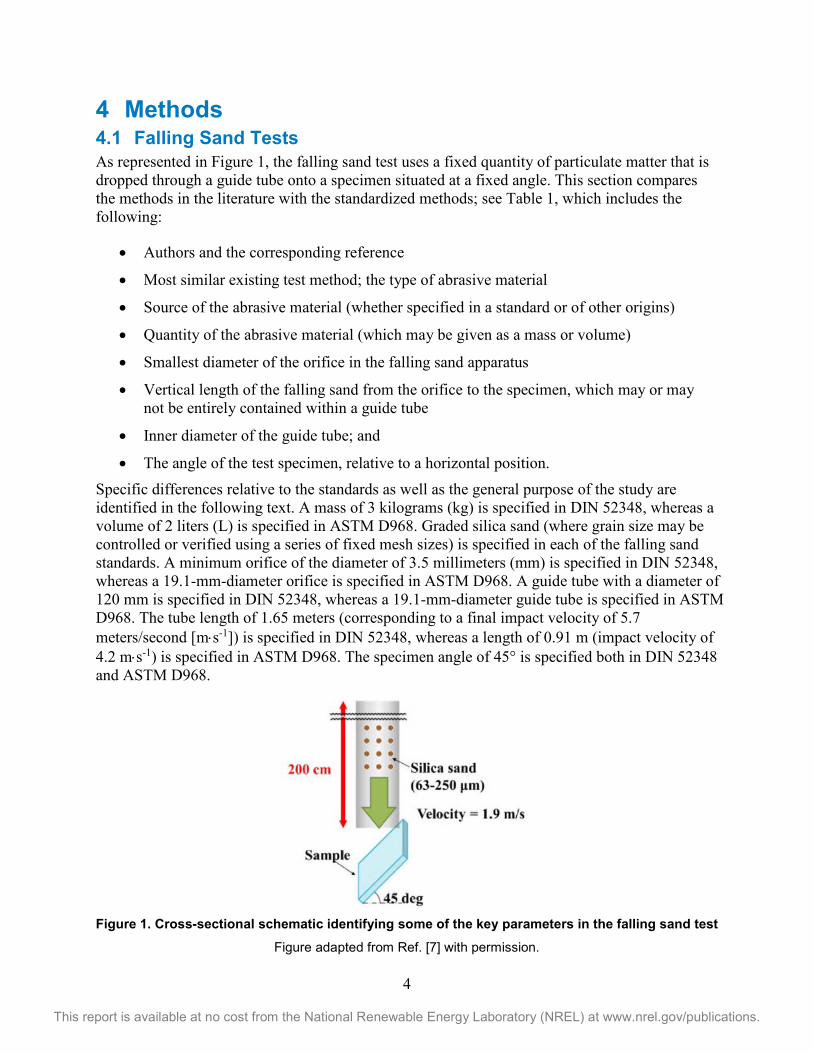
4 Methods 4.1 Falling Sand Tests As represented in Figure 1, the falling sand test uses a fixed quantity of particulate matter that is dropped through a guide tube onto a specimen situated at a fixed angle. This section compares the methods in the literature with the standardized methods; see Table 1, which includes the following:
• Authors and the corresponding reference
• Most similar existing test method; the type of abrasive material
• Source of the abrasive material (whether specified in a standard or of other origins)
• Quantity of the abrasive material (which may be given as a mass or volume)
• Smallest diameter of the orifice in the falling sand apparatus
• Vertical length of the falling sand from the orifice to the specimen, which may or may not be entirely contained within a guide tube
• Inner diameter of the guide tube; and
• The angle of the test specimen, relative to a horizontal position. Specific differences relative to the standards as well as the general purpose of the study are identified in the following text. A mass of 3 kilograms (kg) is specified in DIN 52348, whereas a volume of 2 liters (L) is specified in ASTM D968. Graded silica sand (where grain size may be controlled or verified using a series of fixed mesh sizes) is specified in each of the falling sand standards. A minimum orifice of the diameter of 3.5 millimeters (mm) is specified in DIN 52348, whereas a 19.1-mm-diameter orifice is specified in ASTM D968. A guide tube with a diameter of 120 mm is specified in DIN 52348, whereas a 19.1-mm-diameter guide tube is specified in ASTM D968. The tube length of 1.65 meters (corresponding to a final impact velocity of 5.7 meters/second [m⋅s-1]) is specified in DIN 52348, whereas a length of 0.91 m (impact velocity of 4.2 m⋅s-1) is specified in ASTM D968. The specimen angle of 45° is specified both in DIN 52348 and ASTM D968.
Figure 1. Cross-sectional schematic identifying some of the key parameters in the falling sand test
Figure adapted from Ref. [7] with permission.
5
This report is available at no cost from the National Renewable Energy Laboratory (NREL) at www.nrel.gov/publications.
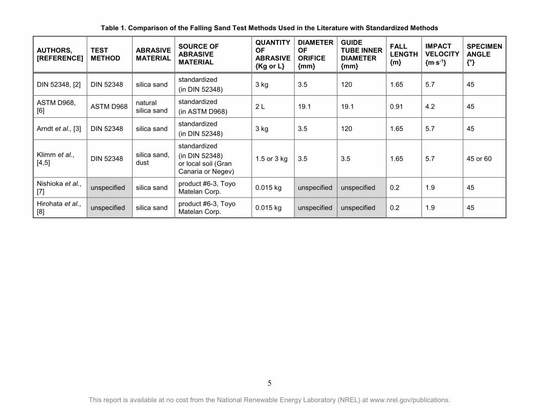
Table 1. Comparison of the Falling Sand Test Methods Used in the Literature with Standardized Methods
AUTHORS, [REFERENCE]
TEST METHOD
ABRASIVE MATERIAL
SOURCE OF ABRASIVE MATERIAL
QUANTITY OF ABRASIVE {Kg or L}
DIAMETER OF ORIFICE {mm}
GUIDE TUBE INNER DIAMETER {mm}
FALL LENGTH {m}
IMPACT VELOCITY {m⋅s-1}
SPECIMEN ANGLE {°}
DIN 52348, [2] DIN 52348 silica sand standardized (in DIN 52348)
3 kg 3.5 120 1.65 5.7 45
ASTM D968, [6] ASTM D968 natural
silica sand standardized (in ASTM D968)
2 L 19.1 19.1 0.91 4.2 45
Arndt et al., [3] DIN 52348 silica sand standardized (in DIN 52348)
3 kg 3.5 120 1.65 5.7 45
Klimm et al., [4,5] DIN 52348 silica sand,
dust
standardized (in DIN 52348) or local soil (Gran Canaria or Negev)
1.5 or 3 kg 3.5 3.5 1.65 5.7 45 or 60
Nishioka et al., [7] unspecified silica sand product #6-3, Toyo
Matelan Corp. 0.015 kg unspecified unspecified 0.2 1.9 45
Hirohata et al., [8] unspecified silica sand product #6-3, Toyo
Matelan Corp. 0.015 kg unspecified unspecified 0.2 1.9 45
6
This report is available at no cost from the National Renewable Energy Laboratory (NREL) at www.nrel.gov/publications.
DIN 52348 [2] was used in Ref. [3] to invoke artificial abrasion damage on a poly(methyl methacrylate) (PMMA) lens used for concentrator PV (CPV). Ref. [3] demonstrated the ability to restore surface roughness and corresponding optical performance after polishing the front surface. A lesser amount (1.5 kg) of sand and a different inclination angle (60°) were explored in Refs. [4,5] to reduce the amount of artificial damage of AR/AS-coated PV glass for the DIN 52348 test. The use of local sand (from Gran Canaria island or the Negev desert) was also explored relative to standardized sand in Refs. [4,5]. An unspecified method, featuring 15 grams (g) of silica sand dropped 200 centimeters (cm) (i.e., an impact velocity of 1.9 m⋅s-1), was used in Refs. [7,8]. These tests were performed to compare the durability of coatings (surface functionalized silica or WO3) for PMMA used for CPV lenses.
The falling sand test is used to simulate abrasion resulting from common low-velocity impact events. Because sand, dust, or grit is used as the abrasive medium, it could be argued that the test is intended to strictly simulate natural abrasion from airborne particulate matter. The difficulty, however, is that the existing tests are too severe (i.e., frosting of the glass occurs). In particular, the aggressiveness of the test follows from the high density of impact events combined with their momentum (particle size and composition). To achieve a more representative test, the diameter of the guide tube might be increased to reduce the impact rate to make it more consistent with the nominal rates more typically observed in the field. Second, silica sand may be replaced by another abrasive medium, such as standardized Arizona Test Dust [9], which may better represent the airborne particulate matter. The length of the tube (which controls the impact velocity) and the specimen angle (which affects the proportion of momentum transferred to the specimen) may also be modified to decrease the severity of the falling sand test.
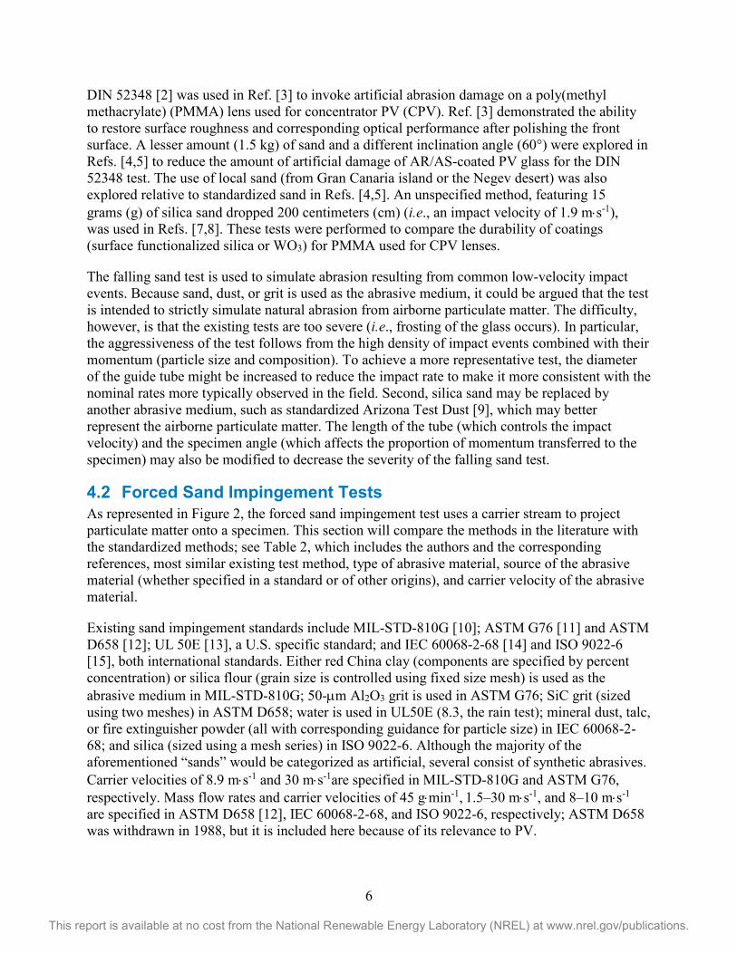
4.2 Forced Sand Impingement Tests As represented in Figure 2, the forced sand impingement test uses a carrier stream to project particulate matter onto a specimen. This section will compare the methods in the literature with the standardized methods; see Table 2, which includes the authors and the corresponding references, most similar existing test method, type of abrasive material, source of the abrasive material (whether specified in a standard or of other origins), and carrier velocity of the abrasive material.
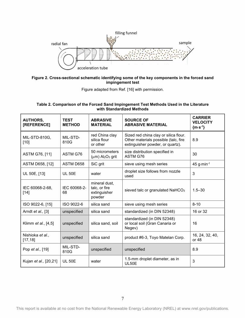
Existing sand impingement standards include MIL-STD-810G [10]; ASTM G76 [11] and ASTM D658 [12]; UL 50E [13], a U.S. specific standard; and IEC 60068-2-68 [14] and ISO 9022-6 [15], both international standards. Either red China clay (components are specified by percent concentration) or silica flour (grain size is controlled using fixed size mesh) is used as the abrasive medium in MIL-STD-810G; 50-µm Al2O3 grit is used in ASTM G76; SiC grit (sized using two meshes) in ASTM D658; water is used in UL50E (8.3, the rain test); mineral dust, talc, or fire extinguisher powder (all with corresponding guidance for particle size) in IEC 60068-2-68; and silica (sized using a mesh series) in ISO 9022-6. Although the majority of the aforementioned “sands” would be categorized as artificial, several consist of synthetic abrasives. Carrier velocities of 8.9 m⋅s-1 and 30 m⋅s-1are specified in MIL-STD-810G and ASTM G76, respectively. Mass flow rates and carrier velocities of 45 g⋅min-1, 1.5–30 m⋅s-1, and 8–10 m⋅s-1 are specified in ASTM D658 [12], IEC 60068-2-68, and ISO 9022-6, respectively; ASTM D658 was withdrawn in 1988, but it is included here because of its relevance to PV.
7
This report is available at no cost from the National Renewable Energy Laboratory (NREL) at www.nrel.gov/publications.
Figure 2. Cross-sectional schematic identifying some of the key components in the forced sand
impingement test
Figure adapted from Ref. [16] with permission.
Table 2. Comparison of the Forced Sand Impingement Test Methods Used in the Literature
with Standardized Methods
AUTHORS, [REFERENCE]
TEST METHOD
ABRASIVE MATERIAL
SOURCE OF ABRASIVE MATERIAL
CARRIER VELOCITY {m⋅s-1}
MIL-STD-810G, [10]
MIL-STD-810G
red China clay silica flour or other
Sized red china clay or silica flour. Other materials possible (talc, fire extinguisher powder, or quartz).
Pop et al., [19] MIL-STD-810G unspecified unspecified 8.9
Kujan et al., [20,21] UL 50E water 1.5-mm droplet diameter, as in UL50E 3
8
This report is available at no cost from the National Renewable Energy Laboratory (NREL) at www.nrel.gov/publications.
Silica sand was blown at 16 or 32 m⋅s-1 in Ref. [3] to study the artificial damage on PMMA for CPV lenses. Silica sand or local soil was blown at 16 m⋅s-1 in Ref. [4] to study the artificial damage on AR/AS-coated PV glass. Silica sand was blown at 16, 24, 32, 40, or 48 m⋅s-1 in Refs. [17,18] to correlate the artificial damage on CPV lenses relative to the momentum of the incident sand. Refs. [17,18] compare the durability of PMMA and glass surfaces, projecting a lifetime base on the rate of observed erosion relative to the momentum of sand encountered in the desert. The aforementioned impingement tests do not reference existing standards. MIL-STD-810G [10] was used in Ref. [19] to examine AR/AS-coated PV glass. Erosion from rainfall (specifically for temperate locations) was emulated using water (1.5-mm droplet size) impacted on AR/AS-coated glass at 3 m⋅s-1 in Refs. [20,21]. Water-facilitated erosion was a concern in that study, because the base material for the coating was a fluoropolymer rather than a ceramic material (e.g., silica). Refs. [20,21] examined the durability (time to wetting and change in sliding angle) of three different coating surface treatments (low, medium, and high roughness).
The forced sand impingement test is used to simulate abrasion resulting from infrequent intense storms. The momentum involved may motivate a different damage mechanism or morphology than ordinary low-velocity abrasion. High-velocity impact events may occur a few times per year in desert or other relevant locations. As with the falling sand test, the choice of sand, dust, or grit used as the abrasive medium is intended to simulate site-specific abrasion. Some studies [17,18] identify a correlation between field exposure and the cumulative momentum of the impacting sand that might be used to determine an acceleration factor for a forced sand impingement test. (The same studies suggest the need to stow modules during severe dust storms). Fortunately, third-party test labs are capable of performing a variety of experimental conditions. The disparate abrasive media and impingement velocities identified in the existing standards, however, suggest the need to identify a set of test conditions appropriate to the PV industry. Gaining consensus for such details may require work to correlate indoor results with the abrasion resulting from challenging field locations. For example, existing meteorological stations, Ref [22], might be used to assess the typical maximum velocity for sand storms. Likewise a minimum velocity should be agreed upon, to define an “intense” sand storm and be able to prescribe a corresponding forced sand impingement test. Such analysis might also provide useful feedback toward falling sand tests.
4.3 Machine Abrasion Tests As represented in Figure 3, machine abrasive tests repeatedly wipe a surface media across a specimen to induce mechanical erosion. This section compares the methods in the literature with the standardized methods; see Table 3, which includes the following:
• Authors and the corresponding references
• Most similar existing test method
• Type of abrasive material
• Size of the abrasive material
• Contact force applied during the test
• Stroke (displacement) length of the abrasive material
9
This report is available at no cost from the National Renewable Energy Laboratory (NREL) at www.nrel.gov/publications.
• Number of machine cycles applied during the test. BS EN 1096-2 [23], ASTM D2486 [24], and ASTM D4060 [25] are commonly used in PV or concentrated solar power (CSP) applications. BS EN 1096-2 uses a dry 14.5-mm-diameter felt pad, which is rotated at six revolutions per minute (rpm) while it is pressed onto the specimen using a 4 N load and wiped across the surface 500 times. Although BS EN 1096-2 is often applied within the PV industry, it remains to be proven whether the standard, written for European building glazings, correlates to results for PV modules used in locations worldwide. For example, one limitation of the test is the pass/fail criteria of 5% loss in transmittance, which exceeds the 3%–4% benefit of an AR coating. In the PV industry, the test would therefore typically require loss of the AR coating and damage to the glass substrate to fail BS EN 1096-2.
ASTM D2486 uses a wet nylon bristle brush that is scrubbed across the specimen in a linear manner, repeated in increments of 400 cycles. The details of ASTM D2486 will be compared to a linear abrasion machine at NREL, which may be configured towards another standard, e.g., DIN 53778-2, [47], described below. The size of brush is unspecified in ASTM D2486; however, an 80-mm x 30-mm bristle area was observed for the NREL instrument, which is similar to what is seen in Figure 3. The contact force is not specified in ASTM D2486, whereas the NREL laboratory instrument operates under the 110-g weight of the brush ~1.1 N. In ASTM D2486, the brush is treated with an abrasive scrub (including silica particulate and liquid chemical components) after each of the 400 cycles, because the grit may be removed by deionized rinse water flow during the test. The equipment (Figure 3) may be made to recirculate or liquid-rinse the original abrasive slurry.
ASTM D4060 uses a dry abrasive wheel (e.g., a rubberized surface, which may contain embedded SiC grit) that is pressed against a turntable with a 1-kg force. The turntable is made to rotate at 72 or 60 rpm (for 110- or 230-volt AC, respectively), while a vacuum is used to remove particulate generated during the test. The number of cycles is not specified in ASTM D4060, but it is often on the order of tens of cycles (i.e., the abrasive wheels must be resurfaced by running them for 50 cycles after each 500-cycle test). ASTM G195 describes the use of the same test apparatus. Commonly described criteria for the assessment of abrasion in ASTM G195 include mass loss; wear index (based on thickness change); wear cycles (to achieve a specified thickness change); volume loss; wear cycles to a specific end-point (thickness change); residual breaking force (typically for fabric specimens in tension); average breaking strength; and percent loss of breaking strength. ASTM G195 describes the Taber abrasion apparatus. It is referenced by many industries for use with specimens including coatings, transparent plastics, carpet, leather, and textile fabrics. ASTM D1044 offers specific guidance for the Taber abrasion of transparent plastics (including the use of 500 gram-force (gf) applied load and the use of 100 cycles or intermittent characterization after 10, 25, 50, and 100 cycles) as well as their optical characterization (instrument acceptance angle of ±1.3° and the use of a 7-mm-diameter mask for the specimen).
10
This report is available at no cost from the National Renewable Energy Laboratory (NREL) at www.nrel.gov/publications.
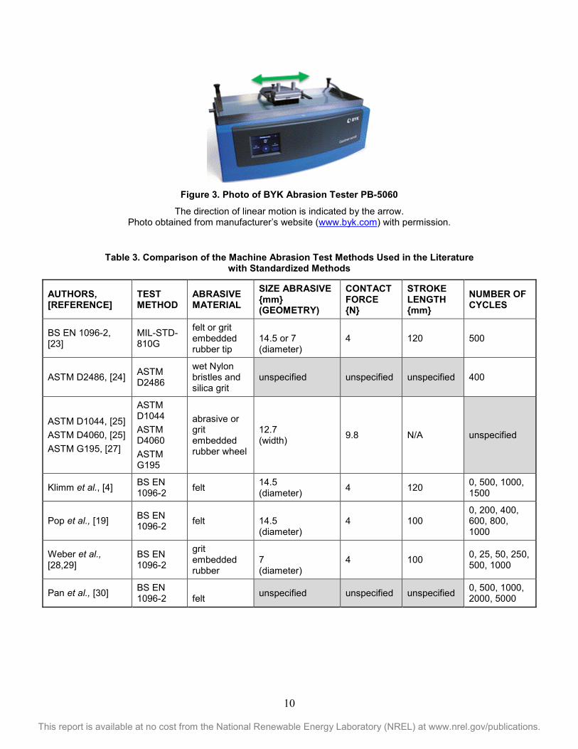
Figure 3. Photo of BYK Abrasion Tester PB-5060
The direction of linear motion is indicated by the arrow. Photo obtained from manufacturer’s website (www.byk.com) with permission.
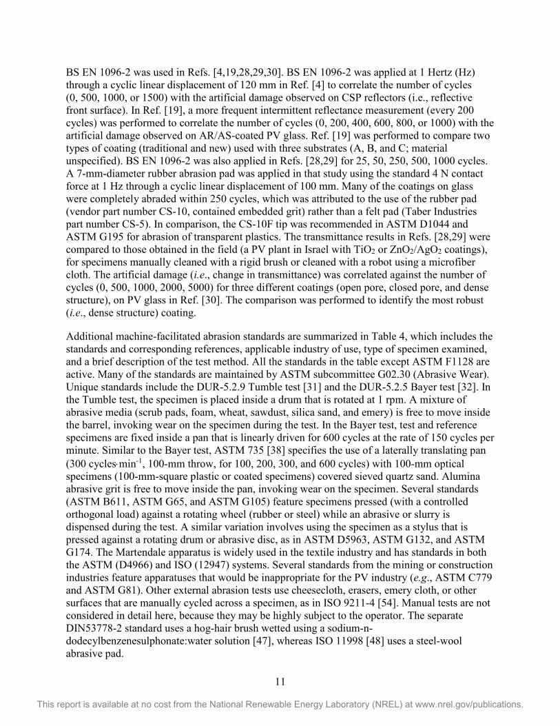
Table 3. Comparison of the Machine Abrasion Test Methods Used in the Literature
with Standardized Methods
AUTHORS, [REFERENCE]
TEST METHOD
ABRASIVE MATERIAL
SIZE ABRASIVE {mm} (GEOMETRY)
CONTACT FORCE {N}
STROKE LENGTH {mm}
NUMBER OF CYCLES
BS EN 1096-2, [23]
MIL-STD-810G
felt or grit embedded rubber tip
14.5 or 7 (diameter)
4 120 500
ASTM D2486, [24] ASTM D2486
wet Nylon bristles and silica grit
unspecified unspecified unspecified 400
ASTM D1044, [25] ASTM D4060, [25] ASTM G195, [27]
ASTM D1044 ASTM D4060 ASTM G195
abrasive or grit embedded rubber wheel
12.7 (width) 9.8 N/A unspecified
Klimm et al., [4] BS EN 1096-2 felt 14.5
(diameter) 4 120 0, 500, 1000, 1500
Pop et al., [19] BS EN 1096-2 felt 14.5
(diameter) 4 100
0, 200, 400, 600, 800, 1000
Weber et al., [28,29]
BS EN 1096-2
grit embedded rubber
7 (diameter)
4 100 0, 25, 50, 250, 500, 1000
Pan et al., [30] BS EN 1096-2 felt unspecified unspecified unspecified 0, 500, 1000,
This report is available at no cost from the National Renewable Energy Laboratory (NREL) at www.nrel.gov/publications.
BS EN 1096-2 was used in Refs. [4,19,28,29,30]. BS EN 1096-2 was applied at 1 Hertz (Hz) through a cyclic linear displacement of 120 mm in Ref. [4] to correlate the number of cycles (0, 500, 1000, or 1500) with the artificial damage observed on CSP reflectors (i.e., reflective front surface). In Ref. [19], a more frequent intermittent reflectance measurement (every 200 cycles) was performed to correlate the number of cycles (0, 200, 400, 600, 800, or 1000) with the artificial damage observed on AR/AS-coated PV glass. Ref. [19] was performed to compare two types of coating (traditional and new) used with three substrates (A, B, and C; material unspecified). BS EN 1096-2 was also applied in Refs. [28,29] for 25, 50, 250, 500, 1000 cycles. A 7-mm-diameter rubber abrasion pad was applied in that study using the standard 4 N contact force at 1 Hz through a cyclic linear displacement of 100 mm. Many of the coatings on glass were completely abraded within 250 cycles, which was attributed to the use of the rubber pad (vendor part number CS-10, contained embedded grit) rather than a felt pad (Taber Industries part number CS-5). In comparison, the CS-10F tip was recommended in ASTM D1044 and ASTM G195 for abrasion of transparent plastics. The transmittance results in Refs. [28,29] were compared to those obtained in the field (a PV plant in Israel with TiO2 or ZnO2/AgO2 coatings), for specimens manually cleaned with a rigid brush or cleaned with a robot using a microfiber cloth. The artificial damage (i.e., change in transmittance) was correlated against the number of cycles (0, 500, 1000, 2000, 5000) for three different coatings (open pore, closed pore, and dense structure), on PV glass in Ref. [30]. The comparison was performed to identify the most robust (i.e., dense structure) coating.
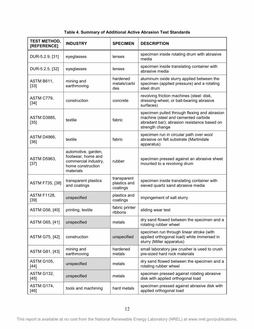
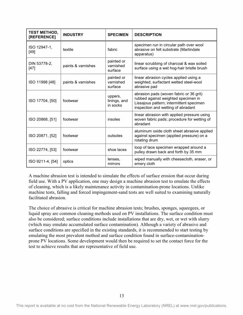
Additional machine-facilitated abrasion standards are summarized in Table 4, which includes the standards and corresponding references, applicable industry of use, type of specimen examined, and a brief description of the test method. All the standards in the table except ASTM F1128 are active. Many of the standards are maintained by ASTM subcommittee G02.30 (Abrasive Wear). Unique standards include the DUR-5.2.9 Tumble test [31] and the DUR-5.2.5 Bayer test [32]. In the Tumble test, the specimen is placed inside a drum that is rotated at 1 rpm. A mixture of abrasive media (scrub pads, foam, wheat, sawdust, silica sand, and emery) is free to move inside the barrel, invoking wear on the specimen during the test. In the Bayer test, test and reference specimens are fixed inside a pan that is linearly driven for 600 cycles at the rate of 150 cycles per minute. Similar to the Bayer test, ASTM 735 [38] specifies the use of a laterally translating pan (300 cycles⋅min-1, 100-mm throw, for 100, 200, 300, and 600 cycles) with 100-mm optical specimens (100-mm-square plastic or coated specimens) covered sieved quartz sand. Alumina abrasive grit is free to move inside the pan, invoking wear on the specimen. Several standards (ASTM B611, ASTM G65, and ASTM G105) feature specimens pressed (with a controlled orthogonal load) against a rotating wheel (rubber or steel) while an abrasive or slurry is dispensed during the test. A similar variation involves using the specimen as a stylus that is pressed against a rotating drum or abrasive disc, as in ASTM D5963, ASTM G132, and ASTM G174. The Martendale apparatus is widely used in the textile industry and has standards in both the ASTM (D4966) and ISO (12947) systems. Several standards from the mining or construction industries feature apparatuses that would be inappropriate for the PV industry (e.g., ASTM C779 and ASTM G81). Other external abrasion tests use cheesecloth, erasers, emery cloth, or other surfaces that are manually cycled across a specimen, as in ISO 9211-4 [54]. Manual tests are not considered in detail here, because they may be highly subject to the operator. The separate DIN53778-2 standard uses a hog-hair brush wetted using a sodium-n-dodecylbenzenesulphonate:water solution [47], whereas ISO 11998 [48] uses a steel-wool abrasive pad.
12
This report is available at no cost from the National Renewable Energy Laboratory (NREL) at www.nrel.gov/publications.
Table 4. Summary of Additional Active Abrasion Test Standards
TEST METHOD, [REFERENCE] INDUSTRY SPECIMEN DESCRIPTION
DUR-5.2.9, [31] eyeglasses lenses specimen inside rotating drum with abrasive media
DUR-5.2.5, [32] eyeglasses lenses specimen inside translating container with abrasive media
ASTM B611, [33]
mining and earthmoving
hardened metals/carbides
aluminum oxide slurry applied between the specimen (applied pressure) and a rotating steel drum
ASTM C779, [34] construction concrete
revolving friction machines (steel: disk, dressing-wheel, or ball-bearing abrasive surfaces)
ASTM D3885, [35] textile fabric
specimen pulled through flexing and abrasion machine (steel and cemented carbide abradant bar); abrasion resistance based on strength change
ASTM D4966, [36] textile fabric
specimen run in circular path over wool abrasive on felt substrate (Martindale apparatus)
ASTM D5963, [37]
automotive, garden, footwear, home and commercial industry, home construction materials
rubber specimen pressed against an abrasive sheet mounted to a revolving drum
ASTM F735, [38] transparent plastics and coatings
transparent plastics and coatings
specimen inside translating container with sieved quartz sand abrasive media
ASTM G65, [41] unspecified metals dry sand flowed between the specimen and a rotating rubber wheel
ASTM G75, [42] construction unspecified specimen run through linear stroke (with applied orthogonal load) while immersed in slurry (Miller apparatus)
ASTM G81, [43] mining and earthmoving
hardened metals
small laboratory jaw crusher is used to crush pre-sized hard rock materials
ASTM G105, [44] unspecified metals dry sand flowed between the specimen and a
rotating rubber wheel
ASTM G132, [45] unspecified metals specimen pressed against rotating abrasive
disk with applied orthogonal load
ASTM G174, [46] tools and machining hard metals specimen pressed against abrasive disk with
applied orthogonal load
13
This report is available at no cost from the National Renewable Energy Laboratory (NREL) at www.nrel.gov/publications.
TEST METHOD, [REFERENCE] INDUSTRY SPECIMEN DESCRIPTION
ISO 12947-1, [49] textile fabric
specimen run in circular path over wool abrasive on felt substrate (Martindale apparatus)
DIN 53778-2, [47] paints & varnishes
painted or varnished surface
linear scrubbing of charcoal & wax soiled surface using a wet hog-hair bristle brush
ISO 11998 [48] paints & varnishes painted or varnished surface
linear abrasion cycles applied using a weighted, surfactant wetted steel-wool abrasive pad
ISO 17704, [50] footwear uppers, linings, and in socks
abrasion pads (woven fabric or 36 grit) rubbed against weighted specimen in Lissajous pattern; intermittent specimen inspection and wetting of abradant
ISO 20868, [51] footwear insoles linear abrasion with applied pressure using woven fabric pads; procedure for wetting of abradant
ISO 20871, [52] footwear outsoles aluminum oxide cloth sheet abrasive applied against specimen (applied pressure) on a rotating drum
ISO 22774, [53] footwear shoe laces loop of lace specimen wrapped around a pulley drawn back and forth by 35 mm
ISO 9211-4, [54] optics lenses, mirrors
wiped manually with cheesecloth, eraser, or emery cloth
A machine abrasion test is intended to simulate the effects of surface erosion that occur during field use. With a PV application, one may design a machine abrasion test to emulate the effects of cleaning, which is a likely maintenance activity in contamination-prone locations. Unlike machine tests, falling and forced impingement-sand tests are well suited to examining naturally facilitated abrasion.
The choice of abrasive is critical for machine abrasion tests; brushes, sponges, squeegees, or liquid spray are common cleaning methods used on PV installations. The surface condition must also be considered; surface conditions include installations that are dry, wet, or wet with slurry (which may emulate accumulated surface contamination). Although a variety of abrasive and surface conditions are specified in the existing standards, it is recommended to start testing by emulating the most prevalent method and surface condition found in surface-contamination-prone PV locations. Some development would then be required to set the contact force for the test to achieve results that are representative of field use.
14
This report is available at no cost from the National Renewable Energy Laboratory (NREL) at www.nrel.gov/publications.
5 Discussion The aforementioned test methods are typically described as not being well suited to PV because they are either too aggressive or destructive to coated and uncoated glass. This conclusion, which can be deduced from some of the references [3,19], was overtly identified within TG12-3. In principle, an industry-applicable, accelerated-aging standard for PV could be developed, but importantly, this would require appropriate validation. To develop the most appropriate test, one must be able to answer the question, “what is more important: natural-induced abrasion or cleaning-induced abrasion?” In other words, is the erosion from particulate impact more damaging than abrasion resulting from the cleaning (removal) of accumulated contamination? There is no industry consensus on the answer to that question, and the answer may depend on the technology (flat-panel PV, use of tracker, or concentrator PV) and the location of the installation as well as the type of cleaning employed.
Not knowing the relative importance of environment-specific abrasion and cleaning-related erosion, the National Renewable Energy Laboratory (NREL) has provisioned to perform a field experiment. Representative coupon specimens (including AR- and AS-coated glass as well as reference glass) will be deployed in soiling-prone locations (Phoenix, Arizona; Sacramento, California; Mumbai, India; northeast Saudi Arabia; and Dubai, United Arab Emirates). Replicate coupons will be deployed at each location that allow for the comparison of popular cleaning methods within the PV industry (i.e., dry brush, wet squeegee, water spray, and uncleaned reference specimens). Specimens from the study will be returned annually for evaluation of transmittance (hemispherical and direct performance and corresponding haze); surface energy (via sessile drop test); and surface roughness (coarse and detailed resolution, if appropriate). Additional characteristics may be evaluated, if appropriate, including: refractive index (via ellipsometry); surface morphology (via scanning electron microscopy); and surface chemistry (via X-ray photoelectron spectroscopy or energy-dispersive X-ray spectroscopy). The field study, starting in 2016, will be used to validate indoor abrasion tests.
Because erosion of the incident surface on PV modules may depend on both location and maintenance, an accelerated abrasion test standard may consist of a series of individual tests. For example, falling sand and forced sand impingement tests are well suited to examining natural abrasion or erosion, whereas a linear abrasion test might be used to simulate the cleaning associated with system maintenance. Regarding the sand tests, these methods were quickly applied to the study of PMMA lenses used in CPV. Like “graded index” (i.e., porous) AR coatings, PMMA is not as hard as bulk glass, possibly making it more susceptible to solid erosion. The advantage of these methods is that the effects of a standardized dust [9] or sand [55, 56] may optionally be compared with those of a local soil or dust. Another benefit of these approaches is that the results of the test may be compared to local meteorological information to validate and determine an acceleration factor. For example, the PV industry may benefit from agriculture and other fields of study, which have examined the wind velocity and distribution of airborne particulate matter in regional locations [57,58,59]. For example, the Gobi desert hosts some of the most abrasive sandstorms on Earth, and the typical storm wind speed there is may exceed17 m⋅s-1 [17,18]. Industry feedback suggests that wind speeds of 4–5 m⋅s-1 might be more representative of average conditions in wind-prone desert locations, but it is unclear whether (1) durability testing will need to align with long-term wear at low wind speeds or (2) the tests will need to mimic the less frequent extreme sand storms. Existing networks of field
15
This report is available at no cost from the National Renewable Energy Laboratory (NREL) at www.nrel.gov/publications.
instrumentation (e.g., as in Saudi Arabia [60]) may be used to prescribe and interpret sand-mediated tests. The simplicity of the sand tests and availability of field data should readily facilitate analysis and life-correlation for glass and coating products.
The greatest difficulties of the linear abrasion test include correlating the results to both cleaning method and surface conditions present in soiling-prone locations. Although brushes, sponges, squeegees, or liquid spray are typically used, there is a benefit of reducing the number of materials used to invoke abrasion during an accelerated test. For example, to reduce the throughput time and the corresponding cost of the test, one would prefer to use just one abrasive medium. The NREL field study should provide critical feedback about both (1) the types of abrasive tips to use during the test and (2) good cleaning practices for PV modules. The extent of surface contamination present during cleaning may vary widely. Because surface contamination can act as grit, invoking surface erosion, the use of a standardized dust, sand, or slurry during a linear abrasion test may be required. The frequency of cleaning at PV installations will complicate the analysis and interpretation of the linear abrasion test. Because the maintenance of a PV installation may be specific to its location or even weather events, establishing an acceleration factor for the test may prove difficult.
16
This report is available at no cost from the National Renewable Energy Laboratory (NREL) at www.nrel.gov/publications.
6 Summary and Recommendations Towards a Test Standard
The general methods of accelerated abrasion testing that might be relevant to PV first surfaces or front sheets have been reviewed based on their use in the PV literature or popular use in other industries. These methods include: falling sand, forced-sand impingement, and machine abrasion. The existing test standards, however, are not well suited to the PV industry, because they are typically too severe for coated and uncoated glass. It is presently not established which mechanism—cleaning abrasion or natural abrasion—is harshest to a PV surface. We hypothesize that multiple procedures might prove appropriate for an international surface durability standard for PV, including methods that use falling sand, forced-sand impingement, and machine abrasion. The falling sand test enables representing the damage caused at relatively low wind speeds typically present at PV installations. The forced sand test allows to simulate the effects of infrequent but damaging storms, where high wind speeds are present. The “sand”-enabled methods allow for the examination of the effect of the environment, and their development will include appropriate parameters associated with the weather in soiling-prone locations. For example, the abrasive medium and carrier velocity for the forced-sand impingement method remain to be demonstrated in order to gain industry consensus and adoption as a standard. A machine abrasion test is relevant when cleaning is anticipated for areas with high soiling, where the natural washing by rain is inadequate. Here, the type of brush or squeegee may be matched to that used for cleaning the PV systems, using an abradant that matches the soil type. A linear abrasion test allows for examination of the effects of cleaning and will be tailored to prevalent cleaning practices in the PV industry. Here also, the details of the test, including the abrasive material and the use of a slurry, will have to be demonstrated in order to facilitate the adoption of a test standard. PVQAT TG12-3 will be used for immediate feedback toward details of the tests.
A field experiment that is part of the U.S. Department of Energy’s SuNLaMP project will be used for long-term feedback toward the details and interpretation of the abrasion standard. The field tests will provide important feedback including the relative importance of natural-induced abrasion or cleaning-induced abrasion; industry guidance concerning the use of cleaning methods (e.g., dry brush vs. squeegee vs. liquid spray); validation of abrasion-related degradation and failure modes; and order-of-magnitude estimation of acceleration factor for abrasion in soiling-prone locations.
17
This report is available at no cost from the National Renewable Energy Laboratory (NREL) at www.nrel.gov/publications.
7 References 1. Travis Sarver, Ali Al-Qaraghuli, and Lawrence L. Kazmerski, “A Comprehensive Review of
the Impact of Dust on the Use of Solar Energy: History, Investigations, Results, Literature, and Mitigation Approaches,” Renew. Sust. Energy Rev. 22 (2013): 698–733.
2. DIN 52348, Testing of Glass and Plastics; Abrasion Test; Sand Trickling Method (Deutsches Institut für Normung, Berlin, 1985), 1–4.
3. Thomas Arndt, Peter Battenhausen, Philipp Kilian, and Roland Sättler, “Polishing Acrylic Lens Materials After Sand Impact,” Proc. Intl. Conf. CPV, AIP Conf. Proc. 1556 (2013): 67–70.
4. Elisabeth Klimm, Thomas Kaltenbach, Michael Koehl, Marvin Masche, Daniel Philipp, and Karl-Anders Weiss, “Soiling and Abrasion of Glazing Material and Mirrors in Extreme Climatic Conditions – Indoor and Outdoor Tests,” Proc. Euro Weathering Symp. (2015).
5. E. Klimm, T. Kaltenbach, D. Philipp, M. Masche, K.-A. Weiss, and Michael Köhl, “Soiling and Abrasion Testing of Surfaces for Solar Energy Systems Adapted to Extreme Climatic Conditions,” Proc. Euro PVSEC (2015).
6. ASTM D968, Standard Test Methods for Abrasion Resistance of Organic Coatings by Falling Abrasive (ASTM International, West Conshohocken, PA, 2015), 1–5.
7. Kensuke Nishioka, Takuya Hirohata, and Yasuyuki Ota, “Simple Anti-Soiling Coating based on Silica for Fresnel Lens of Concentrator Photovoltaic,” Proc. Asian PVSEC (2013).
8. Takuya Hirohata, Yasuyuki Ota, and Kensuke Nishioka, "Anti-Soiling Coating Based on Silica for Fresnel Lens of Concentrator Photovoltaics,” JJAP 54 (2015), 08KE09.
9. ISO 12103-1, Road Vehicles — Test Dust for Filter Evaluation — Part 1: Arizona Test Dust (International Organization for Standardization: Geneva, 1997), 1–9.
10. MIL-STD-810G, Test Method Standard for Environmental Engineering Considerations and Laboratory Tests [Test Method 510.5 Sand and Dust, (Blowing Sand)] (United States Department of Defense, 2003), 1–13.
11. ASTM G76, Standard Test Method for Conducting Erosion Tests by Solid Particle Impingement Using Gas Jets (ASTM International, West Conshohocken, PA, 2013), 1–6.
12. ASTM D658, Standard Test Method for Abrasion Resistance of Organic Coatings by Air Blast Abrasive (ASTM International, West Conshohocken, PA, 1991), 1–3.
13. UL 50E: Enclosures for Electrical Equipment, Environmental Considerations [8.3 Rain Rest] (Underwriters Laboratories, Northbrook, IL, 2007).
14. IEC 60068-2-68, Environmental Testing - Part 2-68: Tests - Test L: Dust and Sand International Electrotechnical Commission: Geneva, 1–127 (1994).
15. ISO 9022-6, Optics and Photonics — Environmental Test Methods — Part 6: Dust (International Organization for Standardization: Geneva, 2004), 1–7.
16. Marvin Masche, “Konzeptionierung einer Prüfmethode zur Untersuchung der abrasiven Einflüsse von Sandpartikeln auf Komponenten von solaren Energiesystemen,” (Bachelor thesis, Technical University Cottbus-Senftenberg, July 2014).
17. Kensuke Nishioka, Kenichi Ikematsu, Yasuyuki Ota, and Kenji Araki, “Influence of Sandblasting in Desert Area on Transmittance of Fresnel Lens for Concentrator Photovoltaic Modules,” Proc. CPV Conf. 2011.
18. Kensuke Nishioka, Kenichi Ikematsu, Yasuyuki Ota, and Kenji Araki, “Sandblasting Durability of Acrylic and Glass Fresnel Lenses for Concentrator Photovoltaic Modules,” Solar Energy 86 (2012): 3021–3025.
18
This report is available at no cost from the National Renewable Energy Laboratory (NREL) at www.nrel.gov/publications.
19. Sergiu C. Pop, Venkata Abbaraju, Brenor Brophy, Y. Sam Yang, Sina Maghsoodi, and Peter Gonsalves, “A Highly Abrasive-Resistant, Long-Lasting Anti-Reflective Coating for PV Module Glass,” Proc. IEEE PVSC (2014): 2715–2719.
20. E. Kujan, B. Farshchian, Q.F. Xu, M. Feldman, and A.M. Lyons, “Superhydrophobic Thermoset Elastomers with Excellent Stability to Rain Erosion and Water Immersion,” Proc. NanoTech Conf. (Adv. Mats. TechConnect Briefs) (2015): 502–505.
21. Q.F. Xu, Y. Zhao, E. Kujan, J.C. Liu, and A.M. Lyons, “An Anti-Reflective and Anti-Soiling Coating of Photovoltaic Panels,” Proc. NanoTech Conf. (Adv. Mats. TechConnect Briefs), (2015): 624–627.
22. Erica Zell, Sami Gasim, Stephen Wilcox, Suzan Katamoura, Thomas Stoffel, Husain Shibli, Jill Engel-Cox, and Madi Al Subie, “Assessment of Solar Radiation Resources in Saudi Arabia,” Solar Energy 119 (2015): 422–438.
23. BS EN 1096-2, Glass in Building. Coated Glass. Requirements and Test Methods for Class A, B and S Coatings (British Standards Institution, London, 2012), 1–34.
24. ASTM D2486 Standard Test Methods for Scrub Resistance of Wall Paints (ASTM International, West Conshohocken, PA, 2012), 1–4.
25. ASTM D1044, Standard Test Method for Resistance of Transparent Plastics to Surface Abrasion (ASTM International, West Conshohocken, PA, 2013), 1–8.
26. ASTM D4060, Standard Test Method for Abrasion Resistance of Organic Coatings by the Taber Abraser (ASTM International, West Conshohocken, PA, 2014), 1–5.
27. ASTM G195, Standard Guide for Conducting Wear Tests Using a Rotary Platform Abraser (ASTM International, West Conshohocken, PA, 2013), 1–8.
28. Thomas Weber, Matthias Hanusch, Simon Koch, Michael Trawny, Andreas Janker, Anja Böttcher, Julieane Berghold, and Paul Grunow, “From the Impact of Harsh Climates and Environmental Conditions on PV-Modules – Development of a Soiling and Abrasion Test,” Proc. Euro. PVSEC, 2014.
29. Nicoletta Ferretti, Aylin Sönmez, Felix Schneider, Bernd Litzenburger, Stefan Janke, Thomas Weber, Juliane Berghold, and Paul Grunow, “Reflectance Measurements for Testing the Effect of Module Cleaning on the Glass Surface,” Proc. Euro. PVSEC, 2015.
30. Xiujuan Pan, Shu Zhang, Jianmei Xu, Zhiqiang Feng, and Pierre J. Verlinden, “Performance of Different Anti-Reflective Coated Glass for PV Modules,” Proc. Euro. PVSEC 2015.
31. DUR-5.2.9, Test Procedure for the Tumble Test (Vision Council of America, 2012). 32. DUR-5.2.5, Method for the Modified Bayer Test (Vision Council of America, 1999). 33. ASTM B611, Standard Test Method for Determining the High Stress Abrasion Resistance of
Hard Materials (ASTM International, West Conshohocken, PA, 2013), 1–6. 34. ASTM C779, Standard Test Method for Abrasion Resistance of Horizontal Concrete
Surfaces (ASTM International, West Conshohocken, PA, 2012), 1–6. 35. ASTM D3885, Standard Test Method for Abrasion Resistance of Textile Fabrics (Flexing
and Abrasion Method (ASTM International, West Conshohocken, PA, 2015), 1–9. 36. ASTM D4966, Standard Test Method for Abrasion Resistance of Textile Fabrics (Martindale
Abrasion Tester Method) (ASTM International, West Conshohocken, PA, 2012), 1–4. 37. ASTM D5963, Standard Test Method for Rubber Property—Abrasion Resistance (Rotary
Drum Abrader (ASTM International, West Conshohocken, PA, 2015), 1–9. 38. ASTM F735, Standard Test Method for Abrasion Resistance of Transparent Plastics and
Coatings Using the Oscillating Sand Method (ASTM International, West Conshohocken, PA, 2011),1–3.
19
This report is available at no cost from the National Renewable Energy Laboratory (NREL) at www.nrel.gov/publications.
39. ASTM F1128, Test Method for Abrasion Resistance of Transparent Plastics and Coatings Using Salt Impingement Method (ASTM International, West Conshohocken, PA, 1988), 1–10.
40. ASTM G56, Standard Test Method for Abrasiveness of Ink-Impregnated Fabric Printer Ribbons and Other Web Materials (ASTM International, West Conshohocken, PA, 2010), 1–4.
41. ASTM G65, Standard Test Method for Measuring Abrasion Using the Dry Sand/Rubber Wheel Apparatus (ASTM International, West Conshohocken, PA, 2010), 1–13.
42. ASTM G75, Standard Test Method for Determination of Slurry Abrasivity (Miller Number) and Slurry Abrasion Response of Materials (SAR Number) (ASTM International, West Conshohocken, PA, 2013), 1–21.
43. ASTM G81, Standard Test Method for Jaw Crusher Gouging Abrasion Test (ASTM International, West Conshohocken, PA, 2013), 1–7.
44. ASTM G105, Standard Test Method for Conducting Wet Sand/Rubber Wheel Abrasion Tests (ASTM International, West Conshohocken, PA, 2007), 1–9.
45. ASTM G132, Standard Test Method for Pin Abrasion Testing (ASTM International, West Conshohocken, PA, 2013), 1–8.
46. ASTM G174, Standard Test Method for Measuring Abrasion Resistance of Materials by Abrasive Loop Contact (ASTM International, West Conshohocken, PA, 2009), 1–7.
47. DIN 53778-2, Emulsion Paints for Interior Use; Evaluation of Cleanability and of Wash and Scrub Resistance of Coatings (Deutsches Institut für Normung, Berlin, 1983), 1-7.
48. ISO 11998, Paints and Varnishes -- Determination of Wet-Scrub Resistance and Cleanability of Coatings (International Organization for Standardization: Geneva, 2006), 1–18.
49. ISO 12947-1, Textiles — Determination of the Abrasion Resistance of Fabrics by the Martindale Method — Part 1: Martindale Abrasion Testing Apparatus (International Organization for Standardization: Geneva, 2010), 1–12.
50. ISO 17704, Footwear — Test Methods for Uppers, Linings and in Socks — Abrasion Resistance (International Organization for Standardization: Geneva, 2004), 1–7.
51. ISO 20868, Footwear — Test Methods for Insoles — Abrasion Resistance (International Organization for Standardization: Geneva, 2001), 1–6.
52. ISO 20871, Footwear — Test Methods for Outsoles — Abrasion Resistance (International Organization for Standardization: Geneva, 2001), 1–9.
53. ISO 22774, Footwear — Test Methods for Accessories: Shoe Laces — Abrasion Resistance (International Organization for Standardization: Geneva, 2004), 1–7.
54. ISO 9211-4, Optics and Photonics — Optical Coatings — Part 4: Specific Test Methods (International Organization for Standardization: Geneva, 2012), 1–14.
55. ASTM C778, Standard Specification for Standard Sand (ASTM International, West Conshohocken, PA, 2013), 1–3.
56. ACETP 300, Climatic Environmental Tests (Allied Environmental Conditions and Test Publications: New York 2006), 1–284.
57. J.P. Thornton, “The Effect of Sandstorms on PV Arrays and Components,” Proc. Solar (1992): 81–85.
58. Mingrui Qiang, Fahu Chen, Aifeng Zhou, Shun Xiao, Jiawu Zhang, and Zhenting Wang, “Impacts of Wind Velocity on Sand and Dust Deposition During Dust Storm as Inferred from a Series of Observations in the Northeastern Qinghai–Tibetan Plateau, China,” Powder Technol. 175 (2007): 82–89.
20
This report is available at no cost from the National Renewable Energy Laboratory (NREL) at www.nrel.gov/publications.
59. Ming Zhao, Ke Jie Zhan, Guo Yu Qiu, Er Tian Fang, Zi Hui Yang, Yin Chang Zhang, and Ai De Li, “Experimental Investigation of the Height Profile of Sand-Dust Fluxes in the 0–50-m Layer and the Effects of Vegetation on Dust Reduction,” Environ. Earth Sci. 62 (2011): 403–410.
60. Erica Zell, Sami Gasim, Stephen Wilcox, Suzan Katamoura, Thomas Stoffel, Husain Shibli, Jill Engel-Cox, and Madi Al-Subie, “Assessment of Solar Radiation Resources in Saudi Arabia,” Solar Energy 119 (2015): 422–438.