Review of Improved Compaction Equipment and Technology FINAL REPORT November 1998 Submitted by NJDOT Research Project Manager Mr. Robert Baker FHWA NJ 1999-11 Dr. Nenad Gucunski* Associate Professor In cooperation with New Jersey Department of Transportation Division of Research and Technology and U.S. Department of Transportation Federal Highway Administration Dr. Ali Maher* Professor and Chairman * Dept. of Civil & Environmental Engineering Center for Advanced Infrastructure & Transportation (CAIT) Rutgers, The State University Piscataway, NJ 08854-8014 Mr. Walid Khouri,* Graduate Research Assistant Mr. William Yanko,* Graduate Research Assistant
Transcript
Review of Improved Compaction Equipment and
Technology
FINAL REPORT November 1998
Submitted by
NJDOT Research Project Manager Mr. Robert Baker
FHWA NJ 1999-11
Dr. Nenad Gucunski* Associate Professor
In cooperation with
New Jersey Department of Transportation
Division of Research and Technology and
U.S. Department of Transportation Federal Highway Administration
Dr. Ali Maher* Professor and Chairman
* Dept. of Civil & Environmental Engineering Center for Advanced Infrastructure & Transportation (CAIT)
Rutgers, The State University Piscataway, NJ 08854-8014
Mr. Walid Khouri,* Graduate Research Assistant Mr. William Yanko,* Graduate Research Assistant
Disclaimer Statement
"The contents of this report reflect the views of the author(s) who is (are) responsible for the facts and the
accuracy of the data presented herein. The contents do not necessarily reflect the official views or policies of the New Jersey Department of Transportation or the Federal Highway Administration. This report does not constitute
a standard, specification, or regulation."
The contents of this report reflect the views of the authors, who are responsible for the facts and the accuracy of the
information presented herein. This document is disseminated under the sponsorship of the Department of Transportation, University Transportation Centers Program, in the interest of information exchange. The U.S. Government assumes no
liability for the contents or use thereof.
1. Report No. 2 . Gove rnmen t Access ion No .
TECHNICAL REPORT STANDARD TITLE PAGE
3 . Rec ip ien t ’ s Ca ta log No .
5 . R e p o r t D a t e
8 . Per fo rming Organ iza t ion Repor t No .
6. Per fo rming Organ iza t ion Code
4 . T i t le and Subt i t le
7 . Au thor (s )
9 . Per fo rming Organ iza t ion Name and Address
10 . Work Un i t No .
11 . Con t rac t o r Gran t No .
13 . Type o f Repor t and Pe r iod Cove red
14 . Sponsor ing Agency Code
12 . Sponsor ing Agency Name and Address
15 . Supp lemen ta ry No tes
16. Abs t r ac t
17. Key Words
19. S e c u r i t y C l a s s i f ( o f t h i s r e p o r t )
Form DOT F 1700.7 (8-69)
20. S e c u r i t y C l a s s i f . ( o f t h i s p a g e )
18. D is t r i bu t ion S ta tement
21 . No o f Pages 22. Pr ic e
November 1998
CAIT/Rutgers
Final Report 12/06/1995 - 6/01/1997
FHWA 1999-11
New Jersey Department of Transportation CN 600 Trenton, NJ 08625
Federal Highway Administration U.S. Department of Transportation Washington, D.C.
The objective of this study was to review the existing and new vibratory roller equipment and technology for improved compaction of subgrade, base, and surface course in the State of New Jersey. A comprehensive literature search was conducted covering all available U.S. and international sources for review of existing systems and identification of new equipment and/or new compaction technology to improve the current practice of NJDOT on compaction of different layers of roads and highways, including recycled materials. The report presented herein consists of the following. An introduction to the history of compaction efforts and an objective to the present study is first presented. Subsequently covered are the general theories behind compaction characteristics of different soils, techniques used for compaction in road construction, and review of existing compaction equipment. The current state of compaction practice in the state of NJ and other states in the country with similar types of soil conditions are then outlined. Next, an up-dated state of practice and relevant equipment technology in Canada, Europe, Japan and other countries is explored. Finally, a detailed presentation of the state-of-the-art in technology and equipment used in compaction works and description of a new compactor for use in asphalt pavement construction are presented. Extensive supporting materials including relevant specifications and guidelines are presented in the appendices attached to the report.
Asphalt, Compaction, Rollers, Equipment, and Vibratory Rollers
Unclassified Unclassified
79
FHWA 1999-11
Dr. Ali Maher, Dr. Nenad Gucunski, Mr. Walid Khouri, and Mr. William Yanko
Review of Improved Compaction Equipment and Technology
Background.......................................................................................................................... 3 Importance of Compaction for Soils and Asphalt Pavement .............................................. 3 Density................................................................................................................................. 3 Impermeability...................................................................................................................... 5 Moisture ............................................................................................................................... 5 Durability .............................................................................................................................. 5
COMPACTION EQUIPMENT.................................................................................................. 7 Smooth Steel Roller............................................................................................................. 7 Grid Rollers.......................................................................................................................... 7 Pneumatic Rollers ............................................................................................................... 7 Sheepsfoot Rollers .............................................................................................................. 7 Vibratory Rollers .................................................................................................................. 8 Plate Compactors................................................................................................................ 8 Thickness of the Layers and Number of Passes.............................................................. 11
REVIEW OF CURRENT NJDOT’S COMPACTION SPECIFICATIONS.............................. 19 CURRENT COMPACTION PRACTICE IN THE U.S............................................................ 19 CURRENT STATE OF PRACTICE IN EUROPE, JAPAN & OTHER COUNTRIES............ 19 SUMMARY OF THE STATE-OF-THE-ART IN TECHNOLOGY & EQUIPMENT USED IN COMPACTION WORKS....................................................................................................... 22
Rollers and Compactors ................................................................................................... 22 Small Rollers and Trench Compactors............................................................................. 29
THEORETICAL/EXPERIMENTAL ACHIEVEMENTS RELATED TO COMPACTION.......... 29 A New Compactor for Asphalt Pavement Compaction..................................................... 29 Simulation of Soil Compaction with Vibratory Rollers....................................................... 33 Compactor Force and Energy Measurements.................................................................. 36 A Compaction Test Method for Soil-Rock Mixtures in which Equipment Size Effects are Minimized........................................................................................................................... 37 Compaction Control of Earth-Rock Mixtures: A New Approach........................................ 38
LIST OF FIGURES Figure 1 Marshall Stability Versus Percent Laboratory-Compacted Density Figure 2 Effect of Initial Air Voids on Change in Penetration of Asphalt Figure 3 Vibratory and Impact Compactors for Shallow Compaction Figure 4 Results of Field Tests Relating Dry Density of Sand Layer to Number of
Passes of 5.7-tonne Vibrating Roller Operating on Surface of 2 m Thick; Compaction Achieved with Same Roller Operating on 0.6-m Lifts
Figure 5 Typical Relationship Between Number of Passes of a Roller and the Density Attained
Figure 6 Dynamic Pressures at Various Depths During Compaction Figure 7 Weight of Different Types of Rollers Figure 8 Sketch of AMIR Compactor Figure 9 Asphalt Multi-Integrated Roller (AMIR) Prototype Figure 10 Self Propelled Vibratory Roller Placed on Soil Model LIST OF TABLES Table 1 Typical Characteristics of Impact and Vibratory Equipment for
Shallow Compaction Table 2 Applicability of Compaction Equipment Table 3 The Contacted Institutions/Organizations in the United States Table 4 The Contacted Overseas Organizations Table 5 Rollers Regarding to Vibration Type Table 6 Special Features of Modern Rollers Table 7 Rollers Regarding to Compacting Medium Table 8 Rollers Regarding to Number of Drums
1
ABSTRACT The objective of this study was to review the existing and new vibratory roller equipment and technology for improved compaction of subgrade, base, and surface course in the State of New Jersey. A comprehensive literature search was conducted covering all available U.S. and international sources for review of existing systems and identification of new equipment and/or new compaction technology to improve the current practice of NJDOT on compaction of different layers of roads and highways, including recycled materials. The report presented herein consists of the following. An introduction to the history of compaction efforts and an objective to the present study is first presented. Subsequently covered are the general theories behind compaction characteristics of different soils, techniques used for compaction in road construction, and review of existing compaction equipment. The current state of compaction practice in the state of NJ and other states in the country with similar types of soil conditions are then outlined. Next, an up-dated state of practice and relevant equipment technology in Canada, Europe, Japan and other countries is explored. Finally, a detailed presentation of the state-of-the-art in technology and equipment used in compaction works and description of a new compactor for use in asphalt pavement construction are presented. Extensive supporting materials including relevant specifications and guidelines are presented in the appendices attached to the report. INTRODUCTION At the beginning of the 20th Century, major discoveries in compaction principles came about because of the higher traffic volume and heavier wheel loads. A scientific approach towards compaction methods was adopted prior to the middle of the century. For highway construction, proper mix design and compaction are two of the main factors which affect the structural performance of asphalt pavements. A high quality mix design cannot achieve a satisfactory pavement life if it is not compacted efficiently. On the other hand, a deficient mix design can have enhanced performance with proper compaction. Therefore, one of the most important factors affecting the performance of asphalt pavements is compaction. Suitable compaction is also a necessity in the underlying layers of a pavement system. The base, subbase, and subgrade layers of a highway system also need to be compacted properly to achieve optimum performance. Improper compaction of these layers may cause unexpected failure of the roadway and thus warrant premature maintenance. A number of compaction methodologies have been utilized to ensure proper compaction. Rollers have been utilized for centuries throughout the world. However, the first sheepsfoot roller did not appear in the United States until 1905. The Bureau of Reclamation and the Corps of Engineer in the United States contributed greatly to the advances in compaction techniques from the 1930’s onward. At the same time in Germany, vibratory compaction of soils came into use [1]. The increases in wheel loads and tire pressures, and the volume of traffic to which modern highways are being subjected to intensely affects the influence of compaction. The following report will discuss the general information regarding compaction techniques and related equipment.
2
OBJECTIVE The work presented here encompasses the review of the existing and new vibratory roller equipment and technology for improved compaction of subgrade, base, and surface course in the state of New Jersey. An extensive literature search was performed encompassing all available international and U.S. sources for review of existing systems and identification of new equipment and compaction technology. The purpose behind this investigation is to improve the current practice of NJDOT on compaction of different layers of roads and highways, including recycled materials. The report presented herein consists of the following items: 1. The general theories behind compaction characteristics of different soils, techniques
used for compaction in road construction, and review of existing compaction equipment. 2. The current compaction practice in the state of NJ and other U.S. states with similar
types of soil conditions. 3. The up-dated state of practice and relevant equipment technology in Canada, Europe,
Japan and other countries in the world. 4. A detailed presentation of the state-of-the-art in technology and equipment used in
compaction practice and the description of a new compactor for the use in asphalt pavement construction.
5. Extensive supporting literature including relevant specifications and guidelines are presented in the six appendices attached to the report.
3
COMPACTION TECHNOLOGY Background Apparently, the first “compressed rock asphalt roadway” was laid in France in 1854 [1]. Early engineers seemingly used sand-sized rock asphalt which was presumably reduced to single absorbed particles by heating and was laid hot and in some ways compacted. The adoption of this phenomenon in the United States took place after it received prosperity in France. By the time asphalt paved roads gained popularity, Lindelof introduced the tandem steamroller in 1875 [2]. Despite its popularity for compaction purposes, tandem steamrollers produced wavy surfaces. Around 1900, rollers were distinguished between tandem rollers for asphalt and three-wheel rollers for macadam. The roller drum was modified in 1938 to add ballast for inducing higher compactive efforts. Also, in 1938, Buffalo-Springfield introduced the three-axle tandem roller. However, the three-axle tandem roller did not fulfill its designed objective to provide a smoother pavement. Importance of Compaction for Soils and Asphalt Pavement The process of compaction has long been recognized as an important factor affecting the performance of the various layers of roads in roadway construction and the performance of huge structures. Major distresses are normally attributed to poor compaction methods. Yet, little attention has been given to the improvement of compaction techniques. Compaction might be the single most critical factor for obtaining satisfactory service life of pavements. The purposes of compaction of sublayers in road construction are as follows:
1. To increase the shear strength 2. To reduce the compressibility 3. To control the swelling and shrinkage 4. To reduce the permeability 5. To prolong durability
Density Many researchers agree that for soils and bituminous materials, an increase in air voids will result in a reduction of strength. For instance, according to Marshall [3], the empirical measure of strength of asphalt concrete by Marshall Stability tends to increase as the void content decreases. Figure 1 illustrates Marshall Stability versus Percent Laboratory-Compacted Density. Finn [4] states that “as the density of the mixture is increased, particularly the degree of packing of the aggregate, the fracture strength is also increased.” A project conducted in North Oakland-Sutherland, Oregon, inferred that “the mix level of compaction is the dominant factor for all mix dynamic properties. Increasing the mix density increases the mix stiffness and fatigue life” [5].
4
FIGURE 1- Marshall Stability versus Percent Laboratory-Compacted Density [6].
5
Impermeability The capability for water and air to penetrate an asphalt mix is called permeability. Permeability has a considerable effect on durability and susceptibility to moisture damage. The reverse process of permeability is also critical and it is known as impermeability. The Asphalt Institute asserts that “Impermeability is the resistance of a pavement to the passage of water and air through it. Impermeability is achieved by making the pavement dense enough to prevent connecting voids in the mass. This can be done by proper compaction of well-designed mixes” [7]. Thick films of asphalt provide durability mainly by orienting the aggregate particles of mixes through low compactive process. Moisture For coarse-grained cohesionless soils and for fine-grained cohesive soils, densification attained is considerably influenced by the moisture content at which the soil is compacted, even though the water may play a different role in the compaction process. Field compaction of free-draining coarse materials shows best results for either dry or completely saturated conditions. If partially saturated, sandy soils may exhibit apparent cohesion due to capillary tension in the pore water, creating attraction forces between the particles which in turn cause frictional resistance against their rearrangement. Surface tension forces are also the reason why some loose dry soils may show densification upon wetting without the application of external forces [8]. Durability Durability of paving mixture is interpreted by Finn [9] as its resistance to weathering, including aging, and to the abrasive action of traffic. McLeod [6] has shown a relationship between retained penetration and air void in the pavement for four year old pavements and the results are illustrated in Figure 2. An investigation on premature failures on a number of roads in Oregon was conducted by Santucci et al. [10]. He stated that “higher air void contents in dense-graded asphalt pavements or overlays accelerate the hardening of the asphalt binder and hence, influence the long-term durability of the pavement.” In many pavements, the primary cause of premature distress was the lack of adequate compaction.
6
FIGURE 2- Effect of Initial Air Voids on Change in Penetration of Asphalt [6]
7
COMPACTION EQUIPMENT Compaction in road construction is achieved by static pressure and/or dynamic pressure caused by impact or vibration on the surface. The most common types of static pressure are smooth steel rollers, pneumatic tired rollers, sheepsfoot rollers and grid rollers. The impact and vibratory equipment are tampers, rammers, plate compactors and vibratory rollers. This report contains details on the features, specifications, advantages and disadvantages of each type of compaction equipment. An emphasis has been placed on reviewing new equipment that have entered the market within the past six years. The general features of each type of roller are as follows: Smooth Steel Roller Traditional steel rollers move at a relatively slower speed than the newer types of equipment. The new rollers exercise high static pressures which qualifies them for granular soils types and on clays because they bridge uneven surfaces. On the other hand, steel rollers may have a plowing effect without resulting in a significant compaction and a poor traction if the soil is soft. Grid Rollers Grid rollers have drums covered or consisting of a heavy steel grid. This creates high contact pressures while preventing excessive shear deformation responsible for the plastic wave ahead of the roll. Grid rollers are suitable for compacting weathered rock, such as stone, by breaking and rearranging gravel and cobble-size particles. Clayey soils, however, may clog the grid and render it ineffective. A relatively high operating speed assists in the breakdown of material, while a lower speed enhances the densification effect [8]. Pneumatic Rollers Pneumatic rollers usually consist of a load cart. The load cart may be towed by a tractor and is supported by a single row of four wheels where the weight from the cart is transmitted to all wheels equally, even if the ground is uneven. This type of roller is most suitable for coarse grained soils with some fines. Sheepsfoot Rollers The surfaces of tamping or sheepsfoot rollers are covered with prismatic attachments or feet, approximately one for every 0.1 m2 (1 ft2). The rollers are utilized for heavy compaction and have a diameter of about 1.5 m and a length of about 1.8 m. When loaded with ballast they have a mass of approximately 15 tonnes . The feet extend at least 0.23 m from the roller and have areas from 0.003 m2 to 0.009 m2. The contact pressure varies from 2000 to
8
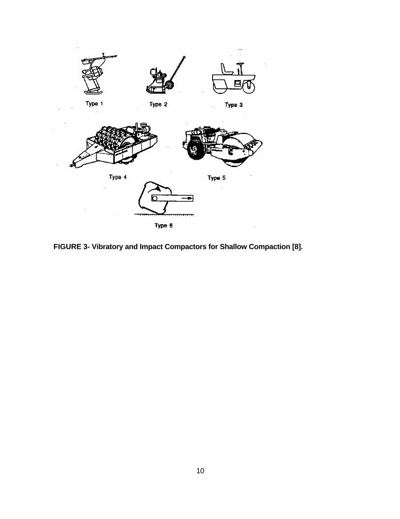
4000 kPa. Smaller and lighter rollers are normally used for highway fills. Those kind of rollers work best with fine-grained soils with significant amount of fines. Vibratory Rollers A Vibratory roller consists of a smooth steel drum in which vibrations are generated by an unbalanced eccentric mass mounted on the axle of the roller or on the frame support by the axle. The frequency of the rotating eccentric mass, and hence the unbalanced force, can usually be varied between a specific range. The drums of comparatively light rollers may have a mass of about 2.7 tonnes, whereas the mass of the drums of heavy rollers (for embankment dams) may be about 9.0 tonnes. The gross mass of the frame and its appurtenances is roughly equal to that of the drum. The normal operating frequency generally lies between 15 and 30 Hz. The dynamic force generated at the lower frequency is usually about equal to the static weight of the drum, and at the higher frequency may exceed the total weight of the drum and frame. The diameter of the drum is usually 1.5 m and the length from 1.8 to 2.7 m. Operating at the frequency close to the first natural frequency of the roller-soil system (resonant frequency) enhances the economy of transition of energy from the roller to the soil. This insures the fewest passes necessary to achieve the specified density. The speed of all types is usually limited to about 5 km/hr. At greater speeds there is likely to be insufficient time for the desired deformation to take place and more passes may be required to achieved the specified density [8]. Vibratory rollers are applied to fine grained soils and also to sand-gravel mixtures. Plate Compactors When the area to be compacted is confined and the above mentioned rollers are not appropriate a vibrating-plate compactors is used. A single plate usually has a mass of not less than 90 kg and the eccentric weight rotates at a frequency not less than 25 Hz. The dynamic increment customarily is limited to the static weight in order to minimize jumping of the plate. A variety of hand-held powered tampers are also available. Their masses range from about 13 to a 100 kg and the diameter of the compaction plate ranges from about 0.1 to 0.25 m. Regardless of the type of soil, the thickness of the lift must be considerably smaller than that of other rollers to achieve comparable compaction. The appropriate soil, on which plate compactors are applied, is coarse-grain soils with 4 to 8% fines. The typical characteristics of impact and vibratory equipment are presented in Table 1 and shown in Figure 3. TABLE 1- Typical Characteristics of Impact and
9
Vibratory Equipment for Shallow Compaction
Typical Characteristics
Type Number & Name
Mass (t)
Max. Working Speed (km/h)
Vibrating Frequency (Hz)
Depth of Lift (m)
Number of Passes
1. Vibrating Rammer
0.3-0.1 - 7-10 0.2-0.4 2-4
2. Light Vibrating Plate
0.06-0.8 1 10-80 0.15-0.5 2-4
3. Light Vibrating Roller
0.6-2 2-4 25-70 0.3-0.5 4-6
4. Heavy Towed Vibrating Roller
6-15 8-10 25-30 0.3-1.5 4-6
5. Heavy Self-propelled Vibrating Roller
6-15 6-13 25-40 0.3-1.5 4-6
6. Impact Roller 7 10-14 - 0.5-3.0 Up to 30
10
FIGURE 3- Vibratory and Impact Compactors for Shallow Compaction [8].
11
Thickness of the Layers and Number of Passes Vibrating rollers are the most effective means for compacting cohesionless soils. The moisture-content control is not critical for such soils. Roller masses customarily range from about four tonnes for sand and sandy gravel soils with lift thickness’ of up to 0.45 m, to about 10 tonnes for rockfill or coarse granular materials with lift thickness’ of up to 1 m. A high density is usually produced in 2 to 8 coverages and the roller frequency typically lies in the range 18 to 25 Hz [11]. On any specific project, the applicability of the foregoing generalities may need to be verified. For example, D’Appolonia et al. (1969) [11] carried out field tests on a large project to ascertain the optimum layer thickness and number of coverages of a 5.7 tonnes roller operating at 27.5 Hz to achieve a relative density of 75% in a uniform sand. Tests on a single layer of 2 m thickness led to the result shown in Figure 4a, from which it was judged that 5 coverages would produce the required compaction to a depth of about 0.75 m. Accordingly, a tentative lift thickness of 0.6 m was selected and tests were carried out after several successive layers were compacted. The result, shown in Figure 4b demonstrated that the procedure was satisfactory and slightly conservative. However, because it was more economical to use lift thickness of 0.45 m with only 2 passes per lift, the latter criterion was adopted. The figure also shows that by any procedure the top 0.25 m remained uncompacted. Tests of this type are justified to establish the most economical procedure to achieve the required compaction at a particular site.
Figure 4 (a) Results of Field Tests Relating Dry Density of Sand Layer to Number
12
of Passes of 5.7-tonne Vibrating Roller Operating on Surface of Layer 2 m Thick. (b) Compaction Achieved with Same Roller Operating on .6-m Lifts [11].
13
A recommended number of 4 to 6 passes are normally required for the use of vibratory rollers (see Table 1). An exception may apply to saturated sands, where the compaction at depth seems to continue to improve with an increasing number of passes, such as up to 15 to 20. For static rollers and rollers equipped with sheepfoot or padfoot drums, the minimum number of passes recommended is usually in the range of 4 to 8 [8]. Figure 5 shows the similar typical relationship between the number of roller passes and the density. Most effective compaction is said to be achieved in the range up to the number of passes associated with the point of maximum curvature. A high number of passes may lead to increased crushing of particles at the interface between the compactor and the soil. This could cause undesirable stratification of the fill, e.g., by creating preferred shear planes (lack of bonding between adjacent layers) or affecting the overall permeability. Minimizing the number of passes may therefore have technical as well as economical advantages. The layer depth which can be satisfactorily compacted is indirectly proportional to the pressure required to effectively compact the soil. This in turn is a function of the type of soil. According to Forssblad (1977,1981), a vertical stress of 50 to 100 KPa is sufficient for vibratory compaction to sand. Clay requires considerably more pressure: 400 to 700 kPa. In sand the motion of soil particles induced by vibration reduces internal friction, which aids in the rearrangement of the sand grains under the influence of shear strain. This is not likely to happen in clays. Figure 4 illustrates the depth effect of different types of compactors. The same concept could be used to establish the stress range required for effective compaction of sands and clays [8].
14
FIGURE 5- Typical Relationship Between the Number of Passes of a Roller and the Density Obtained. [Adopted from Kyulele (1983)]
15
In summary the following conclusions could be drawn: • The effect of the degree of saturation on compactibility is very small in free-draining
materials compared to that of clays. Partially saturated cohesionless soils may develop apparent cohesion because the surface tension force in the pore water cause suction, which increases frictional resistance against compaction. In such a case, it is recommended to compact these soils either when they are completely dry fully saturated [8].
• The compaction of the cohesionless materials close to the surface is difficult because of lack of confinement. This is demonstrated in Figure 6 which shows the typical variation of density with depth before and after compaction [8]. Hence, it is more economical to compact the layer to the desired density after the overlying layer is placed.
• The compacted lift thickness, the number of passes, the type of soil and the weight and type of roller are dependent parameters. For coarse grain materials, the compacted lift thickness of 0.15 to 0.45 m is recommended in road construction. The vibratory rollers are the most efficient and economical types of rollers to be used and 4 to 6 passes is optimum. However, the authors recommend to determine the most efficient rollers, compacted lift thickness and the number of passes based on field tests on test embankments as follows:
1. Construct different test embankments with the same roller, same number of passes but different compacted lift thicknesses.
2. Determine the density of the compacted soils for depths greater than 0.1m. 3. Draw a curve showing the density vs. depth for each lift. 4. Determine the maximum lift thickness, (Ht), that resulted the specified density
for depths > 0.10 m.
16
FIGURE 6- Dynamic Pressures at Various Depths During Compaction. [12].
17
5. Construct another set of different test embankments with lift thickness equal to Ht but, different rollers (when available) and different number of passes for each roller (2 to 8).
6. Draw a set of curves showing the density vs. the depth for each rollers and for different number of passes.
7. The roller that resulted the required density for depths >0.1 m with the minimum number of passes is the most efficient and economical one, provided that the grains are not crushed so that it results a different grain size distribution.
Table 2 assists in the initial selection of the roller. The production rate also assists in the selection of the most economical compaction equipment [8].
PBest
n= 1000
where, P = production rate, m3/h B = drum width, m
e = efficiency (allow 0.7-0.85 for overlap between adjacent passes and the time required to change direction, stop and star)
s = rolling speed, Km/h t = layer thickness, m
n = number of passes
18
TABLE 2- Applicability of Compaction Equipment
Equipment Most-Suitable Soils
Typical Applications
Least-Suitable Soils
Smooth Wheel Rollers, Static or Vibrating
Well-graded sand-gravel mixtures, crushed rock, asphalt
Running surface, base courses, subgrade for roads and runways
Uniform sands
Rubber-Tired Rollers
Coarse-grained soils with some fines
Road and airfield subgrade and base course proof-rolling
Coarse uniform cohesionless soils, and rock
Grid Rollers Weathered rock, well-graded coarse soils
Dams, embankments, subgrade for airfields, highways
Clean coarse-grained soils, soils with cobbles, stones
Vibrating Sheepsfoot Rollers
As above, but also sand-gravel mixtures
Subgrade layers
Vibrating Plate (light)
Coarse-grained soils, 4 to 8% fines Small patches Cohesive soils
Tampers, Rammers
All types Difficult-access areas
Impact Rollers Wide range of moist and saturated soils
Subgrade earthworks (except surface)
Dry, cohesionless soils
19
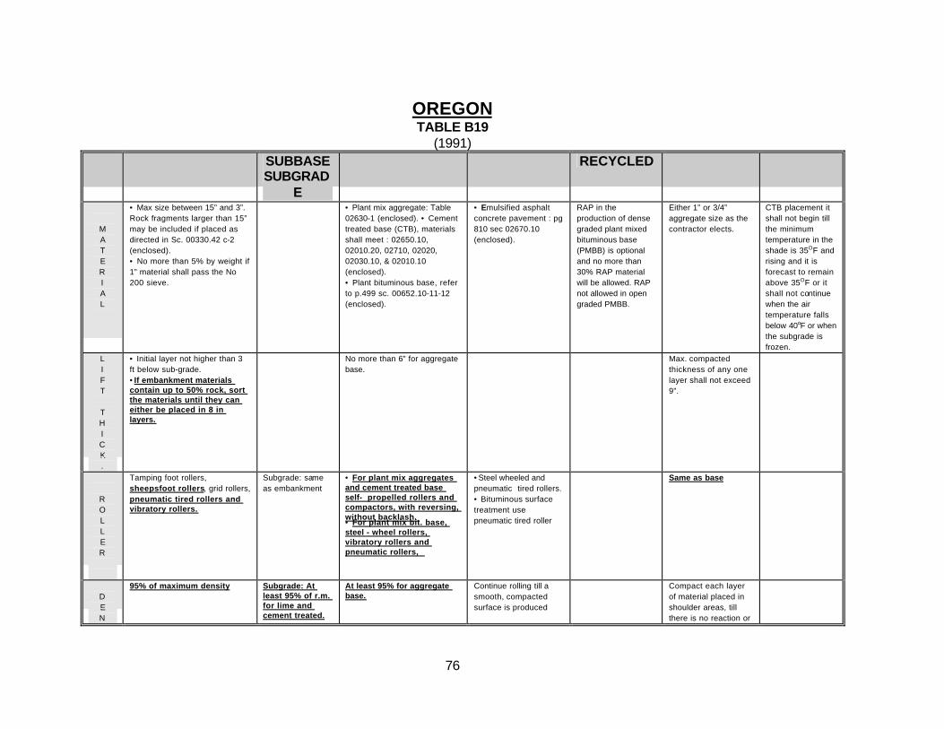
REVIEW OF CURRENT NJDOT’S COMPACTION SPECIFICATIONS This chapter reviews the New Jersey Department of Transportation Standard Specifications for Road and Bridge Construction, 1989. Table A1 (Appendix A) lists some related subsections to the scope of this study. Sections listed in Table A2 (Appendix A) are also shown to be related to the scope of the text. Review has shown that the NJDOT is continuously modifying and updating the standard specifications for Road and Bridge Construction, 1989 .These modifications can be in part, attributed to the impetus to utilize recycled or reclaimed materials in new highway construction or existing roadway resurfacing. The updates can be found in "Standard Input Update ", (SI)* . The most recent SI (SI89 Road 8, Geotek 3 ) issued by the state is dated October 6, 1995. Table 4 lists the general subsections related to roadway construction. The related ADUs (All Design Units) subsequent to October 6 have also been enclosed in this table. Finally, the following subsections and items 4, 6, 7, 8, 16 & 18 of Table A3 (Appendix A) have been recognized to be potentially related to the scope of this study : A summary of all studied specifications and other related materials is presented in Table A3. This table presents the material type and gradation, the proposed lift thickness, the type of suggested roller(s), and the required density in comparison with the standard used for compaction of a particular layer. The subject is covered in different columns, each for a specified layer of the road, i.e. embankment, subgrade/subbase, base course, top course, recycled material and shoulders. If no specification has been covered by the standard references, it has been left blank. CURRENT COMPACTION PRACTICE IN THE U.S. The standard specifications of twenty four other states with relatively similar soil conditions to New Jersey have been collected and reviewed. The subjects related to the scope of this study have been extracted and presented in Tables B1 to B25 and Appendix B. The specification of the different layers of road construction have been compared with the NJDOT's specification. When a significant similarity has been recognized, it has been highlighted and underlined in the tables. CURRENT STATE OF PRACTICE IN EUROPE, JAPAN & OTHER COUNTRIES This chapter covers the type of material as in the previous chapter, but it pertains to international standards and practices. Many contacts were made to international institutions/organizations and foreign government representatives in the United States as
* The Standard specification section 100- General provision, New Jersey highway Authority, (NJHA), 1991 and the Supplementary specifications done by NJHA on subsections 203.10, 301.05, 404.08 and 404.16 which is related to the scope of this study, have been reviewed. These supplementary specifications closely resemble the SI updates.
20
well as related organizations overseas. It is considered a time consuming process to find the right organization to contact. The following sections are summary of the obtained information. The sources are also mentioned here. However, some of the documents were not published in English and it was difficult to translate them into English. At this stage of the report, the extraction of the interested subjects to be compared with the NJDOT's specifications was not possible. All materials related to compaction technology and equipment of Overseas Countries, Europe and Japan are given in Appendix 2. TABLE 3- The Contacted Institutions/Organizations in the United States
1 Global Engineering Documents, A Division of Information Handling Services Inc., 15 Inverness Way East, Englewood, CO 80112, Tel. (800)624-3974, (303)792-2181.
2 British Info (NY), Tel. 212-752-5747 3 British Consulate (NY), Tel. 212-745-0200 4 German Consulate (NY), Tel. 212-308-8700 5 French Consulate (NY), Tel. 212-606-3600 6 Greek Consulate (NY), Tel. 212-988-5500 7 German Commerce Department (NY), Tel. 212-974-8830 Ext. 8834 8 Japanese Cnsulate (NY), Tel. 212-371-8222 9 Bechtel Group Inc., San Francisco, CA, Tel. 415-768-1234 10 Brown & Root Inc, Houston, TX, Tel. 713-676-3011 11 Caterpillar Inc., Peoria, IL, Tel. 309-675-1000 12 H. B. Zachry Co., San Antonio, TX, Tel. 210-922-1213 13 Kieuntt Construction Group Inc., Omaha, Nebraska, Tel. 402-977-4500,
402-342-2052 Ext. 2820 14 Dillingham Construction Holdings Inc., Pleasanton, CA, Tel. 510-463-3300
2 Italy: ANAS, Ente Nazionale Per Le Strade, Direzion General, Ente Pubblico Economico Istituito Con D.L. vo 26/02/1994 no. 143. P.I. 02133681003-C.F. 80208450587, 00185 Roma - Via Monzambano 10, Tel. (06)44461, Fax (06)4456224, 4454956
3 England: The Institution of Civil Engineers, One Great George Street, Westminster, London, SW1P3AA, United Kingdom, Tel. (0171)2227722, Fax (0171)2227500
Fax: 011 44 181 996 7000 7 British Standard Institute: Construction Assistance, Tel. 011 44 181 996
7111 Fax. 011 44 181 996 7408
8 Brown & Root Inc., (Engl.), Tel. 011 44 181 544 8382, 011 44 181 544 5000 9 Heavy Construction Dept. (Geneva), Caterpillar, Tel. 011 41 22 849 4444 10 Japan: JSA, International Standardization Cooperation Center,
Fax 81 3 3582-2390
22
SUMMARY OF THE STATE-OF-THE-ART IN TECHNOLOGY & EQUIPMENT USED IN COMPACTION WORKS Rollers and Compactors During the past five years, the compaction equipment market encountered a large number of new and improved models of rollers for soil and asphalt compaction. In general, the feature characteristic of modern rollers could be grouped as follows: Maneuverability Requests for compaction close to walls and obstacles, led towards the models with improved maneuverability for use in confined spaces.
Models that satisfy this characteristic are: • Ammann Duomat DTV453 (asphalt) • Caterpillar PF-200 • Dynapac CA251PDB (clay)
Environmental Requests
One of the most desirable characteristic for new rollers is their ability to result in less impact on the original environmental conditions. Primarily this refers to the effective noise reduction during the compaction activities.
Models that satisfy requests on surrounding noise reduction are: • Ammann Duomat DTV453 (asphalt) • Bomag BW161AD
Models that satisfy requests on in-cab noise reduction are: • Bomag BW161AD • Stavostroj VSH400
Beside the noise reduction, propagation of the vibration waves towards surrounding structures is the next important issue related to environmental requests. Oscillatory rollers are especially suitable for that purpose.
Models that support oscillation vibration are: • Hamm DV06, Hamm 2410-SDO (soil), Hamm 2414-SDO (asphalt)
Operation Versatility
Different vibration frequencies or the possibility to switch between single and double-drum vibration is the next characteristics found among modern rollers.
Today’s tendency is to equip the rollers with the highly sophisticated devices that can perform complex compaction-control monitoring operations. One of the most interesting monitoring device is called a terrameter. The terrameter gives users on-line information on
23
the progress of compaction while rolling and thus can in some cases save time by reducing the number of passes made by the roller.
Model equipped with terrameter is: • Bomag BW213D
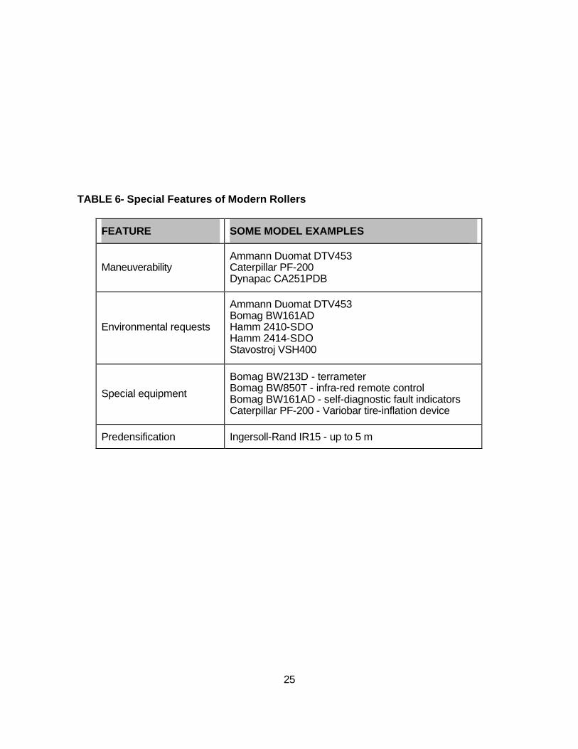
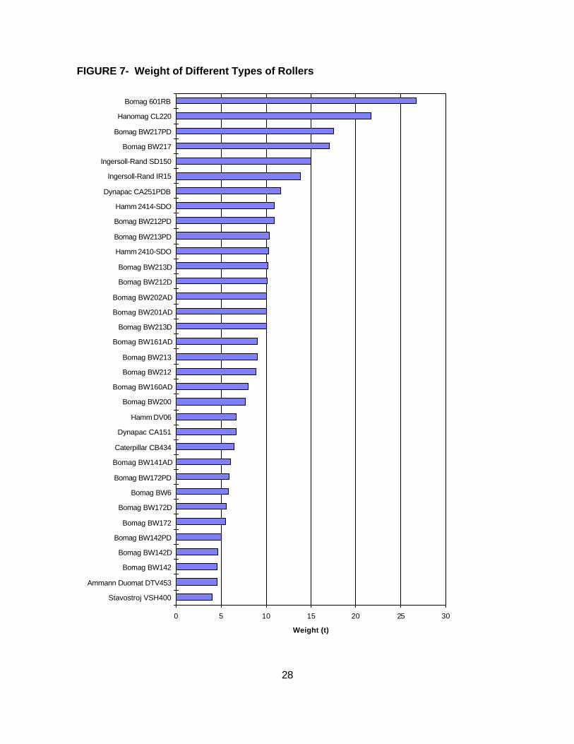
Among other interesting features of modern rollers, it is necessary to mention further development of impact rollers (Ingersoll-Rand IR15). Using an impact roller allows for achievement of higher values of dry density (compared with a vibratory roller). In addition, impact rollers allow predensification up to 5 m, and the moisture content is less critical for these machines than for conventional compaction methods. Summary of different features characteristic to modern rollers are given in Tables 5, 6, 7 and 7, and in Figure 7. Characteristics and technical data of available types of rollers are given in Appendix 3.
Small Rollers and Trench Compactors Small rollers and trench compactors are manufactured mostly by Ammann, Bomag, Ingersoll-Rand and Rammax. Their general characteristics are a weight of up to 2 tonnes and a roller’s width of 190-1000 mm. Some of them are specially equipped and have capability to compact materials up to 800 mm below road surface levels. Small rollers usually have a low center of gravity, high operating weights and a remote control option. Their design is compact so they can access sites where space is tight. Trench compactors could be smooth or sheep-foot. Sheep-foot compactors are considered to be better for two reasons. First, they effectively extract water from the material being compacted, which makes them suited to wet soils and clay. Second, sheep-foot compactors produce more traction, enabling them to cope with wet, wintry conditions. Characteristics and technical data of available types of small rollers and trench compactors are given in Appendix 3. THEORETICAL/EXPERIMENTAL ACHIEVEMENTS RELATED TO COMPACTION A New Compactor for Asphalt Pavement Compaction Field compaction has long been recognized as one of the most important factors affecting the performance of asphalt. In the field, the compaction of asphalt mixture have shown that currently used compaction equipment have a number of significant deficiencies. The cylindrical shape of the drum or wheel, coupled with higher stiffness of its steel material, results in a mismatch in the order of relative rigidities of compacting devices and the compacted structure. Asphalt compaction problems are due to the compaction process itself and not due to the mix properties, aggregate properties, and asphalt cement properties [9]. To summarize the problems with asphalt compactors:
• Construction cracks are a result of compaction by cylindrical steel rollers. • Pneumatic-rubber rollers do not eliminate these construction cracks. • Construction cracks, the legacy of steel wheel rollers, are detrimental to long term
performance of asphalt pavements. An analytical model, supported with laboratory simulation, has shown that the cracks are mainly a result of geometry and material of the drum. The use of pneumatic roller failed to eliminate any of the cracks left by the vibratory roller. Field trials were conducted at:
• Ottawa, field trial in August 1989, • Ottawa, field trial in May 1991, • Egypt, compaction of sand layer on top of strong subbase layer, • Toronto, compaction of asphalt mix on top of subbase layer.
The results of the Toronto and Egypt showed that for the same asphalt mix, construction-induced cracks are mainly caused by the roller. The field trial in Ottawa showed that the
30
steel vibratory roller induced surface cracks. Pneumatic rollers failed to eliminate any of the cracks left by the vibratory roller. A new self-propelled prototype roller was designed in Canada and completed in 1989. The Asphalt Multi-Integrated Roller, AMIR, replaces the cylinder shape with a flat plate and provides a flexible material at the asphalt/compactor interface. The AMIR compactor consists of at least two larger drums with a special thick rubber belt integrating both drums into one flat surface. Small rollers are added on the top of the rubber belt between the two main drums to ensure that a more uniform pressure distribution is achieved at the belt/asphalt interface (Fig. 8 and 9).
It was shown that the use of the new AMIR compactor provided a crack free asphalt pavement. The applied pressure under the AMIR compactor is about 10% to that applied by the steel roller. The stress under the AMIR compactor is vertical. The AMIR compactor achieved better uniformity and comparable densities at lower number of passes. During the previously mentioned field trials, several samples were recovered for density and air voids measurements. Specimens were also tested to determine indirect tensile strength, direct tensile strength, flexural strength, stripping resistance, and fatigue resistance. Asphalt cores were subdivided into two groups. The first group was tested to determine the fatigue tensile resistance to transverse cracking. Thus the test load was applied perpendicular to the rolling direction. The second group was loaded parallel to the direction of rolling to determine the fatigue tensile resistance to longitudinal cracking. The test results showed that the fatigue life of AMIR-compacted asphalt sections was consistently higher than that of the same asphalt mix when compacted with current equipment. The coefficients of variation of the AMIR compacted samples are consistently lower than those calculated for the other compaction methods. The results show that the fatigue resistance of the asphalt has been improved by a factor ranging from 1.4 to 8.1 because of the elimination of construction cracks. This is particularly important in cold regions where the fatigue resistance during winter could drop 20% to 50%. The degree of compaction is found to be dependent on the period of loading as well as the applied pressure. For the same speed, the contact time between the AMIR compactor and asphalt mix is 1.08 sec., which is 30 times of the existing compactors. The results obtained from Ottawa field trial suggest that the new compaction method will provide at least comparable if not better densities than those obtained by other rollers. The occurrence of stripping within weeks after construction suggests that the initial conditions of the compacted layer contribute to the stripping mechanism. The presence of surface hairline cracks are found to create conductive conditions for stripping. The AMIR compaction method provided an asphalt layer with the same strength in both vertical and horizontal directions. The results also show that roller checking does in fact have detrimental effect on tensile strength and fatigue resistance, and increases vulnerability to stripping. To conclude, the AMIR compacted section showed a remarkably crack free surface with tighter texture. The effect of construction cracks are very significant on the future pattern of cracking during the life of the pavement. Fatigue lives of the steel compacted test sections are significantly affected by the direction of the roller in the field. The use of AMIR compactor increased the fatigue performance. Simulation of Soil Compaction with Vibratory Rollers Vibratory rollers are primarily used for compaction tasks in earthwork and road construction. The benefits of dynamic compaction led to vibratory rollers taking a share of more than 90 percent of the total roller market. The compaction effectiveness has to be controlled by adjusting the machine's parameters (i.e., excitation frequency and force, roller speed and number of roller passes). A correlation between a measurable quantity at the drum and the
34
state of soil compaction must be verified. Solving the above problem requires a mathematical description of the interdependence between the state of roller operation and the state of compaction of the building material. For this purpose a calculation model for simulating all states of operation of the roller/soil system is necessary. The mathematical description of the interaction between roller and the soil during compaction requires an analytical model comprising:
• An analytical model for the roller and • A mathematical model which describes the qualities of the soil relevant to
compaction The analytical model can be built as a set of discrete mechanical elements such as masses, springs, and dampers or it can be described as continuous. All model based calculations are only approximation of the actual vibration and compaction behavior. Due to the complex effects inside the soil it is not possible to describe the internal processes during compaction mathematically. The primary demand of the soil model is to describe the plastic and the elastic-plastic deformations. The model of the roller consists of the drum mass md, the frame mass mf, and the frame suspension with the spring kf, and the damper df. The drum is set into vibration by the excitation force Fe. The soil model includes a mass ms (representing the mass of the soil that has been caused to vibrate by the drum), a system with mass ma, spring ka, and damper da, (necessary to control the motion of the soil mass during bounce operation of the drum) [see Figure 10]. Roller parameters: The technical data of a specific machine can be used as model parameters. However, if a new machine is designed, the parameters can be chosen freely. Soil parameters: The soil model requires the determination of the vibrating soil mass, the stiffness of springs and the parameters of the additional system. The total stiffness and the vibrating soil mass cannot be derived directly from soil properties. The model parameters must instead be calculated from measurable characteristics of the roller/soil system, i.e. static soil deformation, natural frequency or time responses of the drum and frame acceleration. The displacement-time graph shows that there are time domains where drum and the soil mass are vibrating conformably (contact operation) and domains where drum and the soil mass have different displacements (bounce operation).
35
FIGURE 10- Self-Propelled Vibratory Roller Placed on Soil Model.
36
The acceleration-time diagram shows that the curve of the drum acceleration is not entirely sinusoidal but becomes distorted at certain times caused by the changes in the mode of drum operation. Around the operation frequency the course of the drum acceleration is nearly constant. Therefore these values of the drum acceleration are independent of the excitation frequency. With the amplitude of the excitation force getting greater, the increase in drum acceleration tends to lower frequencies. Compactor Force and Energy Measurements During compaction, the vertical force from the compactor tends to displace soil laterally. After compaction, horizontal stresses in the compacted soil can exceed the at-rest stresses that exist in normally consolidated soil. If the vertical contact force exerted by the compactor on the soil is known, compaction-induced pressures can be determined. The Light Equipment Manufacturer’s Bureau (LEMB) does provide procedures for rating hand-operated compactor forces. The rated energy determined by the LEMB method should be a fairly realistic measure of the actual energy the compactor will apply to the soil since energy is the basis of the rating method. On the other hand, the rated force is only a nominal value since it is based on an assumed soil deflection. For example, variations in soil stiffness between dry and wet soil will be accompanied by variations in deflection and contact forces even if the energy per blow remains constant. Consequently, actual compactor forces are not expected to be the same for all soils, and they could be quite different from the rated force (the rated force represents an average, and the peak force could be higher or smaller). Several procedures for estimating the dynamic compactor force for vibratory rollers have been developed. According to several experimental results, the total dynamic force from a vibratory roller is about 1.4 to 3 times the static roller load. Before this conducted study, there have been no reported measurements of the dynamic forces for hand-operated compactors. Two hand-operated compactors are analyzed: rammer compactor and vibrating plate compactor. For the rammer compactor, the peak contact forces ranged from 15 700 to 38 000 N and averaged 24 500 N. The peak contact force increased with increasing soil stiffness. The average measured energy transfer was 71.0 J per blow, which is close to the manufacturer’s rated energy of 78.4 J per blow. However, the manufacturer’s rated force of 12 300 N is much lower than the measured peak forces. The LEMB rating procedure gives a reasonable estimate of the energy delivered per blow from a rammer compactor. However, the LEMB-rated force yields only a nominal value. For the vibrating plate compactor, peak forces ranged from 4600 to 7500 N and averaged 5650 N. Measured peak forces were much less than the manufacturer’s rated centrifugal force of 24 000 N. The LEMB does not provide a method for rating the energy transfer for vibrating plate compactors.
37
A Compaction Test Method for Soil-Rock Mixtures in which Equipment Size Effects are Minimized Laboratory tests to obtain moisture-density relationships for soil-rock mixtures have been both problematical and questionable for many years. Because the ratio of specimen diameter to largest particle size should be no less than 5 or 6, equipment for testing soil-rock mixtures containing particle sizes greater than 25.4 mm is much larger and considerably more expensive than equipment utilizing 102 and 152 mm diameter molds. Large-scale equipment and accompanying procedures are usually developed on an individual basis and may vary considerably even though most tests are performed using standard compactive efforts. The problem with variations in equipment and procedures is that they may produce different values of maximum dry unit weight and optimum water content obtained from tests performed on the same material at the same compactive effort. Since strength-deformation properties of soil-rock mixtures may vary significantly with small changes in unit weight and water content, differences in compaction test results due to equipment size and procedures could have a significant effect on predicted soil behavior. This suggests the need for developing large-scale testing equipment and procedures in which equipment size effects are minimized. Because of the often prohibitive cost of large-scale equipment and testing, various methods have been used to model full-scale materials. The goal has been to create tests that can be performed using conventional equipment for the prediction of full-scale results. The two most common methods in current use are the scalping and replacement procedure (U.S. Army Corps of Engineers 1980) and ASTM Practice D 4718 for the Correction of Unit Weight and Water Content for Soils Containing Oversize Particles (ASTM 1994). According to the U.S. Bureau of Reclamation (USBR), it has been determined that both methods provide results that diverge from those values obtained from the testing of full-scale materials as oversize particle content is increased. Procedures for the 305 and 457 mm diameter molds were developed. A series of standard effort 152 mm diameter mold compaction tests were performed on materials having a maximum particle size of 19.1 mm. Then a series of standard effort 305 mm diameter mold tests were performed on the same materials in order to determine a hammer weight that would reproduce the 152 mm diameter mold results. The hammer weight decided upon for use with the 305 mm diameter mold procedure was then used to perform a series of standard effort 457 mm diameter mold tests on the same materials to determine whether it could also be used for that case. In both cases, the number of blows per layer was adjusted to achieve standard compactive effort while the remainder of the procedure was identical to that used for the 152 mm diameter tests. Final test results indicated that use of the 152 mm diameter mold and 59.6 kg hammer provide a satisfactory means of minimizing equipment size effect for 305 and 457 mm diameter mold. Differences in results for the 305 mm diameter mold compared to those obtained with the 152 mm diameter mold were less than 1% for optimum water content and less than 0.5 kN/m3 for maximum dry unit weight. Differences in results for the 457 mm diameter mold were even smaller; less than 0.5% for optimum water content and less than 0.1 kN/m3 for maximum dry unit weight. It is therefore concluded that soil-rock mixtures
38
having a maximum particle size of 19.1 mm tested in a standard 152 mm diameter mold represent adequately results for soil-rock mixtures tested in 305 and 457 mm diameter molds with maximum particle sizes up to 51 or 76 mm respectively. Results of the investigation also indicated that such procedures may not satisfactorily minimize equipment size effects for 4.75 mm sieved materials tested in the same size molds. Compaction Control of Earth-Rock Mixtures: A New Approach Soils containing gravel particles (earth-rock mixtures) present laboratory and field problems because compaction testing of the total gradations requires large specimens, associated large-scaled equipment, and time-consuming procedures. It has been assumed that the results of compaction tests performed on the altered gradations can be directly related to or are equivalent to those of the total materials. However, such an assumption may not be very accurate or valid for many materials. Different testing procedures were developed which derive a different gradation from the total material to reduce the maximum particle size in order to perform compaction testing in either the 102 mm or 152 mm diameter mold. The presence of the coarse fraction can be accounted for by the scalp-and-replace method where the material greater than 19.1 mm is replaced by an equal weight of material between the 4.75 mm and 19.0 mm sieves. An alternative is to use a rock correction equation and compaction test results, usually on the fine fraction. The rock correction equation methods generally give higher estimates of the maximum dry density than the scalp-and-replace method. Specifications that cover different correction equations are: AASHTO T224, ASTM D4718 and USBR 5515-89. It should be noted that all cited methods give different results for the same tested material and the differences have been found to be the most significant for clayey soils. One of the most popular correction equation, used widely because of its simplicity, is cited in the Housmann’s book “Engineering Principles of Ground Modification” (see Appendix 1). This method is based on the test results of the material with particle sizes no larger than 19 mm, which is tested in the standard 105 mm diameter mold. It should be noted again that this method, as all other correction equations in use, may lead to overestimation of field values, especially if the proportion of the removed material (particle size above 19 mm) is significant. Procedures for obtaining the maximum dry unit weight and an optimum water content of the total material from corresponding values obtained on either the 19.1 mm or 4.76 mm fraction were developed. Calculations of maximum dry unit weight and optimum water content of the total material from corresponding values for a fraction are made using a density interference coefficient and optimum water content factor. Correcting the dry unit weight of a fraction of the total material for the presence of gravel: Ziegler’s equation* (ASTM D 4718), used to correct dry unit weight of the total material is valid prvided the finer fraction completely fills the voids between the particles of the oversized
* For exact equations see Appendix 4.
39
fraction and the voids associated with the oversized fraction by means of the bulk specific gravity remain constant. For this approach to be accurate, the presence of the gravel would have to produce no effect on the compaction of the finer fraction. To avoid this problem, the density interference coefficient Ic is defined. It relates the fraction density factor (percent compaction of the finer fraction when the total material is at its maximum dry unit weight for either the 19.1 mm or 4.76 mm fraction) to the gravel content and the bulk specific gravity of the total material. When the coefficient is based on the 4.76 fraction, it has been shown to be linearly related to gravel content in log-log coordinates over a range in gravel content from 10 to 50%, and linearly related to gravel content in Cartesian coordinates between gravel content of 50 and 70%. That allows a simple procedure of reading its values from the linear graphs. Correcting the water content of a fraction of the total material for the presence of gravel: Corrected water content of the total material is calculated using the optimum water content of the finer fraction. This practice is however subjected to significant error, especially considering the typical specification ranges on placement water content as referred to optimum for most gravely soils. The new method accurately relates the optimum water content of the total material to that of a fraction by introducing the optimum water content factor, FOPT. It relates the optimum water content of either the 19.1 mm or 4.76 mm fraction to that of the total material and its gravel content. It is linearly related to gravel content in log-log coordinates over a range from 10 to 70% and can be easily obtained from the linear graph. The use of laboratory determination of the maximum dry unit weight and optimum water content is based on the implicit assumption that the material compacted in the lab is substantially equivalent to the material compacted in the field. For soil-rock mixtures however, this assumption is generally not correct. Two methods are proposed in order to solve this problem:
• large-scale testing equipment and procedures in which equipment size effects are minimized
• correction equations for the presence of gravel. The first method showed to be successful in using material for testing with particle sizes of up to 19 mm and adequate testing equipment. Relating them to soil-rock mixtures with maximum particle size greater than 19 mm would require larger sized and more expensive equipment. The second method showed to be successful in using the correction equations. This eliminates the problems raised from use of existing correction formulas, to obtain the soil-rock mixture properties if the maximum particle size of tested material is 19.1 or 4.76 mm and gravel content does not exceed the range of 10 to 70%. Sources of all presented subjects are given in Appendix 4. CONCLUSIONS
40
The process of compaction has long been recognized as an important factor affecting the performance of the various layers of roads in roadway construction and the performance of huge structures. Some of the critical factors that affect roadway performance and are in large part related to compaction techniques include in place density, impermeability, moisture, and durability. Using the proper compaction technique and equipment, these factors can be properly controlled. Applicability of the different types of rollers are presented in table 2. In choosing the proper type of roller or compactor, a number of factors must be considered. For compaction close to obstacles, maneuverability must be considered. Environmental considerations such as noise control may also be factor in choosing a compactor. Versatility in operation should also be considered; for example, compactors that have variable frequency vibration and single/double roller interchangability. A new piece of equipment available on the Bomag BW213D is a compaction monitoring terrameter. In evaluation of small rollers and trench compactors, sheeps-foot compactors are considered better than plate compactors for two reasons. Sheeps-foot compactors more effectively extract water from the compacted material and produce more traction, which is good for wet or wintry conditions. A new compactor known as the Asphalt Multi-Integrated Roller (AMIR) has been evaluated because of its ability to avoid construction cracks in asphalt pavements. Construction cracks are a usually a result of the steel rollers of conventional compactors. These cracks are detrimental to the long term performance of pavements. The AMIR consists of a dual steel drum assembly with a thick rubber belt spun around the rollers. It was shown in previous field trials that this compactor provided a crack free asphalt pavement and that the fatigue life of these sections was greatly extended. A way to simulate soil compaction under a vibratory roller has also been explored. The purpose of producing this type of model is to describe plastic and elastic-plastic deformations. The input parameters of the model include drum mass, frame mass, frame suspension, excitation force which are then interpreted into a set of springs and dampers. This model is dynamic in nature; meaning that specific soil and compactor parameters of a particular job site can be used as input. In exploring laboratory compaction methods of field materials, a method for simulating in-situ conditions for moisture-density relationships has been explored. The previously used mold sizes and hammer weights have proven to be inadequate for consistent dry unit weight and optimum moisture content lab measurements. These factors then affect strength deformation properties. The current testing results indicated that a 152 mm diameter mold and a 59.6 kg hammer for sample compaction seemed to be adequate for soils with a maximum particle size of 19.1 mm. For determination of maximum dry unit weight and optimum moisture content has also been a problem in laboratory compaction of earth-rock mixtures. Two ways to simulate field compaction of these mixtures are large scale testing equipment and correction equations for the presence of gravel. Large scale testing equipment proved to be adequate for particle sizes up to 19 mm in size. Larger sized particles in the material would require larger more
41
expensive equipment. Correction equations were adequate for samples with maximum particle sizes of 19.1 to 4.75 mm and gravel contents from 10 to 70%. RECOMMENDATIONS • The proper roller or compactor should be used based on the soil type to attain favorable
results in considering moisture, density, impermeability, and durability. For soil mediums, the effects of moisture and density of the main concerns. For bituminous materials, the main factors to be considered are density, impermeability, and durability.
• Maneuverability, noise control, and operational versatility should be considered when choosing a compactor. Table 6 provides compactors that are specially built with these factors in mind.
• A terrameter would decrease construction time by possibly decreasing the number of passes. The Bomag BW213D is the only compactor in this study that is equipped with a terrameter. If cost effective, it would be beneficial to retrofit other compactors with this device.
• For trench compaction of wet soils and clay, a sheeps-foot compactor is preferable over a plate compactor due to its traction and moisture extraction.
• The AMIR can increase asphalt pavement life by decreasing construction crack distresses and would in theory be a better compactor. However, the SHRP program of the early 90’s envisaged the relation between laboratory and field performance. Because validation between laboratory and field compaction was only made for smooth steel rollers, a specification has not been established thus far.
• For performing plastic and elastic plastic analysis of soils under vibratory compaction, a mathematical model can be used. This system consists of a series of dampers and springs based on compactor and soil parameters. This type of model is useful in evaluating new compactors; but it does not have a practical use for evaluating field compaction at this time.
• For laboratory simulation of field materials with maximum particle sizes of 19.1 mm, compaction should be done in a 152 mm mold with a 59.6 kg hammer. Larger samples compacted in 305 and 457 mm molds showed very little difference in general laboratory test performance.
• For earth-rock mixtures, laboratory compaction should consist of large scale equipment or the use of correction formulas. Corrections formulas are less expensive and faster then purchasing large equipment.
42
REFERENCES 1. Hughes, Charles S., Virginia Transportation Research Council, “Compaction of Asphalt
Pavement”, Transportation Research Board 152, 1989. 2. Tunnicliff, D. G., R.W. Beaty, and E.H. Holt, “A History of Plants, Equipment and Methods
in Bituminous Paving”, Proceedings, Association of Asphalt Paving Technologists, Vol. 43A, 1974.
3. Marshall, B.G., “Investigation of the Design and Control of Asphalt Paving Mixtures,” Vols. 1 and 2, U.S. Army Waterways Experiment Station, Vicksburg, Miss., 1948.
4. Finn, F.N., NCHRP Report 39: Factors Involved in the Design of Asphaltic Pavement Surfaces, Transportation Research Board, National Research Council, Washington, D.C., 1980.
5. Walter, J., R.G. Hicks, J.P. Mahoney, and J.E. Wilson, Jr., “Effect of Mix Variations on Asphalt Pavement Life: North Oakland-Sutherland Project,” in Transportation Research Board Record 843:Asphalts, Asphalt Mixtures, and Additives, Transportation Research Board, National Research Council, Washington, D.C., 1982.
6. McLeod, N.W., “Influence of Viscosity of Asphalt-Cements on Compaction of Paving Mixtures inthe Field,” Highway Research Record No. 158: Bituminous Concrete Mixes: 6 Reports, Highway Research Board, National Research Council, Washington, D.C., 1967.
7. “Factors Affecting Compaction,” Education Series No. 9 (ES-9), The Asphalt Institute, College Park, Md., 1980.
8. Hausmann, M. R., “Engineering Principles of Ground Modification”, Mc Graw Hill, 1990. 9. Finn, F.N., NCHRP Report 39: Factors Involved in the Design of Asphaltic Pavement
Surfaces, Transportation Research Board, National Research Council, Washington, D.C., 1967.
10. Santucci, L.E., D.D. Allen, and R.L. Coats, “The Effect of Moisture and Compaction on the Quality of Asphalt Pavements,” Proceedings, Association of Asphalt Paving Technologists, Vol. 54, 1985.
11. D’Appolonia, D. J., Whitman, R. V., and D’Appolonia, E., “Sand Compaction with Vibratory Rollers”, ASCE Journal of Soil Mechanics, 1995.
12. Forssblad, L., (1977), “Vibratory Compaction in the Construction of Roads, Airfield, Dams and Other Projects”, Report No. 8222, Dynapac, S-17122 Solna 1, Sweden.
13. Terzaghi, K., “Peck, R. B., and Mesri, G. H., Soil Mechanics in Engineering Practice”, Third Edition, John Wiley interscience, 1966.
14. Das, B. M., “Principles of Geotechnical Engineering”, Third Edition, Int. Thomson Publishing, 1994.
15. Fang, H. Y., “Foundation Engineering Handbook”, Second Edition, Van Nostrand Reinhold, 1991.
16. Forssblad, L., (1981), “Vibratory Soil and Rock Compaction”, Dynapac Maskin AB, Solna 1, Sweden.
17. Abd El Halim, A. O., and Hass, R., “Effect of Field Compaction Method on Fatigue Life of Asphalt Pavements”, Transportation Research Record 1469, pp. 43-49.
18. Abd El Halim, A. O., et al, (1993), “Unwated Legacy of Asphalt Pavement Compaction”, ASCE Journal of Transportation Engineering, Vol. 119, No. 6, November/December 1993.
43
APPENDIX A
TABLE A1- General Subsections Related to Roadway Construction
SUBSECTION** ON:
202.04 Excavated bituminous concrete which is not recycled.
202.12 Excess broken concrete and bituminous concrete (related to 202.04 and 202.08 ).
203.03 Size of oversize materials in embankment construction.
Note: Above ADU Memorandums are Enclosed in Separate Binder.
46
APPENDIX B
NEW JERSEY TABLE B1(a)
(1989/95) EMBANKMENT SUBBASE
SUBGRADE BASE COURSE TOP COURSE
M A T E R I A L
• Soil aggregate, portion of material passing #4 contain ≤ 35% of material #200 sieve (1). • For soil & rock, the aggr. rock would be such as to fill all of the rock voids (1). • When piles are to be driven, the max size aggregate shall be 2” (1). • The oversize shall be no greater in any dimension than 12” (2). • Lightweight fill material shall be expanded slate or shale cinders or blast furnace slag where blast furnace slag should conform to sc.901.06 (enclosed) except that the quality requirements are deleted (2).
• Aggr. size #8 @ a range of 15 to 30 lb/yd2 (1). • Bituminous concrete: for top layer, coarse aggr., fine aggr., mineral filler & asphalt cement & may also include 10% RAP. For bottom layer, coarse & fine aggr., mineral filler & asphalt cement & may also include up to 20% RAP (1).
L I F T T H I C K
Max compacted thickness of each layer shall not exceed 8” unless appropriate equipment is utilized (1).
• Subbase: compacted thickness shall not be greater than 8” (1). • Subgrade: compacted thickness shall not be greater than 8” (2).
same as Subbase
R O L L E R
Table203-2 P.130 (enclosed) (1). • Subbase: pneumatic-tire or dynamic compactors (1). • Subgrade: Same as embankment (1).
same as Subbase same as embankment
D E N S I T Y
Each layer compacted not less than 95% of established reference max density. w%= ±2% of opt. (AASHTO T99, Method C) (1), except in control fill method, the minimum acceptance average density of the material in the control strip is from 90% to 95% of its max density (2), whereas in density control test, in no case shall an individual measurement be less than 90% of the max density (2).
Subbase & Subgrade, same as embankment (1).
In compliance with AASHTO T191, T205 or T238, Method B & T239, unless only 1 is specified. w%= ±2% of opt. (1).
• RAP: Density control shall conform to sc.301.05 (enclosed) (1). • When AASHTO T238 , Method B & T239 are used to perform compaction acceptance testing sc. 301.05B (enclosed), a representative sample of 5 tests for each 5000 yd2 lot will be taken (1).
47
(1) Standard Specifications, NJDOT, 1989 (2) Standard Inputs, SI (3) All Design Units, ADUs
48
NEW JERSEY TABLE B1(b)
(1989/95)
RECYCLED MATERIAL
SHOULDERS
REMARKS
M A T E R I A L
• Bituminous Concrete: Top layer may include up to 10% of RAP. In bottom layer, it may include up to 20% of RAP (1). • Excavated bitum. conc. which is not recycled may be placed in lower portion of zone3 embankment. Max size of bitum. conc. shall be 2ft3 (2). • Recycled conc. aggr. shall conform to sc. 901.08 (enclosed) (1). • RAP shall conform to sc. 901.10, 903.01 & 903.04 (enclosed) (1). • For Batch Plant & Drum Mixing Plant: use 26-50% of RAP (3).
• Bituminous concrete shall be coarse aggr., fine aggr., mineral filler & asphalt cement & may also include up to 20% RAP (1). • Dense graded aggr.: Chart P.379 sc.901.08 (enclosed) shall consist of broken stone, crushed gravel, or blast furnace slag (1). • Soil Aggregate: It shall consist of hard durable particles or fragments or fragments of stone, slag, gravel or sand & containing some silt-clay or stone dust (1).
• Broken Portland cement or bituminous concrete in embankment may be allowed to be reused in accordance with sc.202.04 & 202.08 (enclosed) (2). • Aggregates from different sources may be permitted if they are of the same geological classification & have similar specific gravities & color (1).
L I F T T H I C K .
R O L L E R
• Dense graded aggregate & soil aggregate: Pneumatic-tire rollers or dynamic compactors (1). • Bituminous surface treatment: Steel-wheel rollers or pneumatic-tire (1). • Bituminous concrete: 1 or more bitum. conc. plants, bitum. conc. pavers and rollers shall be available (1).
Top Course: When adding stabilizing agent, a traveling plant w/ rotary mixer shall be used (1).
D E N S I T Y
Dense graded aggregate: w% immediately prior to placement shall be +6 or -2% based on dry weight (1).
Base course: A lot must have not more than 20% of the lot area with a dry density of less than 95% of the reference max density (1).
(1) Standard Specifications, NJDOT, 1989
49
(2) Standard Inputs, SI (3) All Design Units, ADUs
50
ALABAMA TABLE B2
EMBANKMENT
SUBBASE
SUBGRADE
BASE
COURSE
TOP
COURSE
SHOULDERS
REMARKS
M A T E R I A L
• Soil classification from borrow materials: Improved roadbed: A-1, A-2, A-3, A-4 (AASHTO M145). • Underwater backfill material: A-3 or approved A-1, A-2 which ≤ 15% passes 75µm sieve. • Underwater embankment materials: 0.5m3 and smaller size stone taken from approved natural rock formation.
L I F T T H I C K .
Each layer shall not exceed 600mm in thickness. But 600mm below the finished subgrade, suitable material with dimension in any direction not exceeding 100mm, shall be placed in layers not exceeding 200mm in loose thickness and compacted.
Maximum of 150 mm compacted thickness in one layer.
Same as Base
R O L L E R
For subbase, up to the Engineer.
Up to the Engineer Same as Base
D E N S I T Y
• AASHTO T99 Method A,C or D. • Method A: used when 10% or less retained on the 4.75mm sieve w/ retained aggregate discarded. • Method C: used when more than 10% aggregate retained on 4.75mm sieve and < 20% retained on 19mm sieve. • Method D: used when more than 20% retained on 19mm sieve. • In place density requirements: 95% for method A,C and 98% for Method D
• AASHTO T180 Method A,C or D (similar to embankment) Table I P.3-18 sc.306.03 (enclosed). • Moisture content same as BASE.
Required density at a uniform moisture content ±2 percentage points of optimum.
AASHTO T209 Table II & III sc.306.03, P.3-18 (enclosed).
Same as Base
No compaction or density test will be required for underwater embankment or underwater backfill.
51
52
CALIFORNIA TABLE B3
(1995) EMBANKMENT SUBBASE SUBGRADE BASE COURSE TOP COURSE REMARKS
M A T E R I A L
l Subbase lime stabilization: contains no rocks or solids other than soil clods, more than 60 mm in any dimension. l Aggregate subbase: Class1,2,3 and shall be clean from organic material or any other deleterious substances and it shall be of such nature that it can be readily compacted under watering to form a firm stable base, (pg. 25-1 grading requirements, (enclosed).
l Lime stabilized base: as subbase . l Aggregate base: material Class 2,3 clean of organic or deleterious matter. Grading requirements, pg. 25-1, (enclosed).
For asphalt concrete, aggregate : grading requirements, sec 39, (enclosed).
L I F T T H I C K N E S S
Embankments constructed in layers of uniform thickness.
Subbases: lime stabilized and aggregate subbases, no more than 150 mm.
Not more than 150 mm for lime stabilized and aggregate bases
E Q U I P M E N T
At locations where it would be impractical to use mobile power compacting equipment, embankment layers shall be compacted by any method that will obtain the specified compaction.
l Initial compaction by sheepsfoot or segmented wheel rollers. Immediately followed with final compaction by rolling with steel drum or pneumatic rollers. l Vibratory rollers : NOT USED l Lime stabilized subbase: areas inaccessible to rollers shall be compacted to the required relative compaction by other means satisfactory to the Engineers.
Lime stabilized : as subbase Bituminous seals : At least : l one steel tired roller, l 2axle tandem roller between 7.2 and 9.1 tons and l a min of 3 rollers consisting of : a. 1 steel tired roller more than 7.2 tons , b. 1 steel tired roller, 2axle or 3 axle tandem or 3 wheel roller more than 11 tons, c. 1 pneumatic tired roller.
D E N S I T Y
l Subbase: lime stabilized soil shall be compacted to the req’d relative density of not < 95% except that the min relative compaction may be reduced at 92% provided that the contractor increases the lime content at 0.5%. l Subgrade: rel. compaction ³ 95 %. For aggregate and lime stabilized subbase compaction ³ 95%.
l Lime stabilized : as subbase l Aggregate base: ³ 95% .
53
CONNECTICUT TABLE B4
(1995)
SUBBASE SUBGRADE
BASE COURSE TOP COURSE RECYCLED MATERIAL
REMARKS
M A T E R I A L
L I F T T H I C K N E S S
Subbase: placed in layers not exceeding 6”. If the total thickness of the subbase is less than 8“, it may be placed in one layer.
l Rolled granular bases 6” thick or less may be constructed in one layer. Larger bases shall be constructed in two equal depth layers. l Gravel base course: Bottom course no more than 4 in after compaction.
E Q U I P M E N T
l Subgrade: static rollers, vibratory rollers . l Subbase: equipment produced safely for that purpose , sec. 2.12.03, (enclosed) .
l Rolled granular base: static power roller, vibratory power roller. l Bituminous base course: power rollers.
Bituminous top course: power rollers.
Cold reclaimed asphalt pavement: vibratory roller
D E N S I T Y
l Subgrade: after compaction density shall be not less than 95% of the dry density of soil tested according AASHTO T180 method D. Compaction at the Wopt. l Subbase: same as subgrade.
Equivalent compactive effort to 10 tons for bituminous top course.
l Minimum of 95% of the proctor wet density (AASHTO T-180) l Cold reclaimed asphalt pavement: compaction 95% of proctor wet density.
54
55
DELAWARE TABLE B5
(1985)
EMBANKMENT
SUBBASE SUBGRADE
BASE COURSE
TOP COURSE RECYCLED
MATERIAL
SHOULDERS
REMARKS
M A T E R I A L
Subbase: Stone, passing 2” sieve & retained on #10 sieve slag. Gravel, pass #4” sieve & retained on #10 sieve. Sand, pass #10 sieve & be retained on #200 sieve. Silt, clay, & stone dust, pass #200 sieve, class A, B & C & Table 8.81 sc.3.2.2 (enclosed).
Same as embankment. Viscosity grade AC20 & meet AASHTO M226.
Bitum. Cold Mix: it could contain up to 25% of washed concrete sand.
Approved material obtained from the right-of-way or approved borrow sources.
Recycled coarse cement used, Portland cement concrete used. Specifications are same as coarse aggr..
L I F T T H I C K
Subbase: Layer thickness shall not exceed 8” after compaction.
R O L L E R
Subgrade: Test rolling is first done w/ self-propelled pneumatic tired rollers.
Up to the Engineer. • Use @ least 2 rollers, one power roller & one self-propelled rubber tired roller. • Steel wheel rollers and pneumatic rubber-tired rollers. • For pneumatic rubber-tired rollers, a min. of 8 passes is required after the initial pass has been made by steel wheel rollers.
D E N S I T Y
• Compaction till density ≥ 95% of maximum density, AASHTO T191, T239 for field density measurement. • Moisture content during compaction within 2% of optimum.
• Subbase of more than 8” total compacted thickness shall be placed & compacted in 2 or more courses of approx. equal thickness. • Bottom course of subbase shall be compacted by a min. of 5 passes w/ pneumatic tire rollers. • Top course & intermediate course, a min. of 5 passes w/ static, a min. of 2 passes w/ vibratory. Moisture content ± 2% of optimum.
• Same as embankment. • Borrow base course: compact until the density ≥100% of maximum density. • w% ≈ 2% of opt. • Aggregate base, w% = -2% of opt.
• Hot - mix bituminous pavement, longitudinal direction rolling should complete within 1 hour of asphalt application. • Compact to a density not less than 95% of density obtained by Lab compaction.
• Soil base to be paved shall be compacted to ≥ 100% of maximum density for the top 6”. • On areas not to be paved or seeded, the maximum density shall be 95%. • Areas to be seeded shall be compacted as directed.
56
IDAHO TABLE B6
(1995)
EMBANKMENT SUBBASE SUBGRADE
BASE COURSE TOP COURSE REMARKS
M A T E R I A L
l Borrow shall be obtained from designated or approved sources. l Granular borrow shall consist of sand, sand gravel and sand rock mixtures and shall be obtained from designated approved sources.
Material or granular subbase shall meet applicable requirements of section 703, (enclosed).
l For road mix pavement: asphalt shall be of the type and grade called for, in the contract. l Aggregates shall meet the applicable requirements of sec. 703 (enclosed). l For plant mix pavement: aggregate at the plant except for plant mix from contractor, (furnished sources approved) asphalt as indicated in the contract, antistripping additive and fly ash.
For road mix pavement: the aggregate to be treated or the mix material below laying shall not contain more than 2% moisture.
L I F T T H I C K N E S S
l Layers shall not exceed 200 mm (8 in) loose thickness. l Material too granular to be tested by Idaho methods T-14 or T-91, shall be constructed in horizontal layers no thicker than 500 mm. No layer shall be thicker than 1 m (3 ft), unless otherwise permitted.
Less than 240 mm (0.8 ft). When vibrating or other approved types of special compacting equipment are used, less than 300 mm (1 ft).
l For emulsion treated bases & aggregate bases: no more than 150 mm. l When vibrating or other approved types of special compacting equipment used, the compacting depth of a single layer of the base may be increased to 250 mm upon approval.
No more than 1 m (3 ft) For subbase the min compacted thickness of any course shall be 1.5 times the maximum particle size.
E Q U I P M E N T
Vibratory rollers, grid rollers. Grid rollers speed no more than 7Km/h. Vibratry rollers speed no more than 2.5 Km/h
l For emulsion treated bases: up to the Engineers. l For aggregate bases: left to contractor. l For cement treated base: steel rollers, pneumatic tire rollers, vibratory rollers.
Plant mix pavement: steel wheel, vibratory or pneumatic tire type.
D E N S I T Y
For class description check pg. 101 sec. 205.14, (enclosed). l Class A compaction: For γmax ≤ 1900 kg/m3 , density 95% of std. For γmax >1900 kg/m3 , density 100% of std. l Class B compaction: shall consist of compaction embankment and backfill, w/ 300 mm of subgrade to the density standards for class A compaction. l Class C compaction: shall consist of compacting of selected areas under embankments to a density standards for class A compaction to a depth of 200 mm. l Class D compaction : pg. 102 sec. 205.14, (enclosed).
l For emulsion treated bases: compaction shall continue until 100% of std density. l For aggregate bases: ³ 95% of std density. l For cement treated base: ³ 96% of maximum dry weight per cubic ft.
l For road mix pavement: rolling shall continue until the surfacing is of uniform texture and satisfactory compaction obtained. l For plant mix pavement: 92-95% of maximum theoretical density for classes I, II, III mix in accordance with T-86 IDAHO.
l For embankment: if the class compaction is not specified, class B compaction will be required. l For cement treated base: compaction shall be completed within 2 hours after water is added to the cement and aggregate mixture.
57
FLORIDA TABLE B7
EMBANKMENT
SUBBASE
SUBGRADE
BASE
COURSE
TOP
COURSE
RECYCLED MATERIAL
M A T E R I A L
Max sizes of rock which will be permitted: • In top 12”, max. permitted size is 3.5”. • From 12” to 2ft, 6” maximum allowed size. • In the depth below 2ft, the maximum permitted size is not to exceed the compacted thickness of layer being replaced.
L I F T T H I C K .
• Material shall be placed in layers not exceeding 18” in thickness, measured loose. • Material deposited in water or on low swampy ground and in layer > 12”, the top 6” in layer shall be compacted in accordance w/ density (See Density).
Maximum loose thickness is 18”.
R O L L E R
Vibratory rollers, trench rollers or other equipment approved by the Engineer.
D E N S I T Y
Layer shall be compacted to not less than 100% of maximum density as determined by AASHTO T99, Method C
Same as embankment
58
59
KENTUCKY TABLE B8
EMBANKMEN
T
SUBBASE SUBGRADE
BASE COURS
E
TOP COURSE
REMARKS
M A T E R I A L
Subgrade: No surfacing layers shall be placed on a frozen, muddy, soft, or yielding surface
L I F T T H I C K .
R O L L E R
• Subgrade: For sheepsfoot roller, 9 complete passes by one roller, for pneumatic tired roller, 6 complete passes by one roller, & for pneumatic tired vibratory roller, 4 complete passes with equipment vibrating and 2 complete passes without vibration.
D E N S I T Y
The subgrade shall be compacted as nearly as practicable to a uniform density throughout.
60
MAINE TABLE B9
(1972)
EMBANKMENT
SUBBASE
SUBGRADE
BASE COURSE
REMARKS
M A T E R I A L
Best possible use should be made of the excavations which are available on the project. Otherwise use appropriate material authorized by the engineer.
Material passing a 3” sieve and oversized stone (not passing the 6” sieve), shall be removed .
L I F T T H I C K N E S S
8”, maximum loose measure.
For subbase no more than 12 in No more than 12“ Embankment: in embankment, with approval, the contractor may place layers in excess of 8” and less than 24“, loose measure, providing the specified compaction requirements are obtained.
E Q U I P M E N T
l Vibratory type of equipment for sandy soils. l Rubber tires for gravel and sheepsfoot rollers for clayey or silty soil.
For subgrade: same as embankment.
D E N S I T Y
l 90% of the maximum laboratory dry density. l Correlation of the number of passes with density: density test is used as a guide, for the determination of the number of passes which must be made by the compacting machinery on each layer to result in a density of 90%.
l For subbase: not less than 95% of max density. l For subgrade : same as embankments.
Same as subbase.
Embankments: for winter construction of embankment, when the prevailing temperatures are below 30o F, all material used in embankment, shall have a moisture content at the time of compaction, equal to or less than the optimum .
61
MARYLAND TABLE B10
EMBANKMENT SUBBASE SUBGRADE
BASE COURSE TOP COURSE RECYCLED MATERIAL
REMARKS
M A T E R I A L
l Rock may be used provided that individual pieces would not exceed 24” (610 mm) in any dimension. l Borrow material has to have more than 35% retained on the #4 sieve.
100% RAP as graded aggregate base material.
L I F T
T H I C K N E S S
l For earth embankment layer should not exceed 8”. l For rock embankments, each layer should not exceed 24”. This layer shall be filled and compacted before next layer is placed.
E Q U I P M E N T
Pneumatic, tired rollers, mechanical tampers, vibratory compactors or up to the Engineers
l Subgrade: same as embankments.
Approved by the Engineers Self propelled rollers, reversible, steel wheeled or pneumatic tired. Vibratory rollers may be used.
D E N S I T Y
l In place density determined by MSMT 320, 352. Test rolling first conducted to determine density required. l Borrow material: maximum dry density of less than 100 p/ft3 is considered unsatisfactory. Max dry density: 100<γd <105 p/ft3
Subgrade: same as embankments. l Material 1 ft below the top of subgrade shall be compacted to ³ 92% of maximum dry density as specified by T180. l Material in top 1 ft shall be compacted to ³ 97% of maximum dry density.
l Aggregate base course: compaction ³ 97% of maximum dry graded stabilized aggregate base. l Base course: compaction ³ 95% of max dry density. In place density MSMT 350.
Hot mix asphalt: compaction 92 to 97% of dry maximum dry density. Temperature shouldn’t go below 135oF before compaction.
62
MASSACHUSETTS TABLE B11
(1988/94) EMBANKMENT SUBBASE
SUBGRADE BASE COURSE TOP COURSE REMARKS
M A T E R I A L
l Ordinary borrow M1.01.0 l Gravel borrow M 1.03.0 l Sand borrow M1.04.0 type B l Gravel borrow for bridge foundation M 1.03.0 type a. l Special borrow M 1.08.0 (All the above sec. enclosed)
l Subgrade: refer to special borrow M 1.02.0 l Gravel subbase: conforming to M1.03.0 type b l Dense crushed stone for subbase (M 2.01.7) (All the above sec. enclosed).
l Reclaimed base course (gravel borrow) M1.03.0 l Gravel base course(gravel borrow) M1.03.0. (All the above sec. enclosed).
Class I bituminous concrete pavement shall conform to M3.11.09, (enclosed).
L I F T
T H I C K N E S S
No more than 12” in depth
l Subbase: no more than 8” in compacted depth except the last layer which will be 4” . l Subgrade: no more than 8” in depth.
l Gravel base course: as subbase. l Base course 6” thick or less in one layer. Larger bases, constructed in two equal layers.
Cold reclaimed asphalt pavement: layers not > 8” in compacted depth, except the last layer , 4” in compacted depth.
E Q U I P M E N T
l Subgrade: power rollers or tamping rollers. l Subbase: as subgrade.
l Gravel base course: power rollers or tamping rollers. l Bituminous base course: steel wheel rollers, pneumatic tired rollers . l Rolled granular base: static power rollers, vibratory power rollers .
l Bituminous top course : steel wheeled rollers, pneumatic tired rollers. l Cold reclaimed asphalt pavement: Power rollers or tamping rollers.
D E N S I T Y
Density ³ 95% of maximum dry density.
l Subgrade: density ³ 95% of γdmax , as determined by AASHTO t99 method C. Compaction at the Wopt. l Subbase: same as subgrade.
l Gravel base course: Compaction ³ 95% of γmax by AASHTO T99 method C. Compaction at Wopt. l Bituminous base course: as top course.
l Bituminous top course: density not less than 95% of that obtained from laboratory compaction of the same material in like proportions. No more than two passes in each direction. l Cold reclaimed asphalt pavement: compaction ³
l Subbase formed from reclaimed aggregate, containing bituminous concrete. Wet density ³ 95% of that subbase, when tested by AASHTO T180, method D. l Base : the same as subbase.
63
pavement: compaction ³ 95% of max dry density as determined by AASHTO test.
64
MICHIGAN TABLE B12
(1990) EMBANKMENT SUBBASE
SUBGRADE BASE COURSE SHOULDERS REMARKS
M A T E R I A L
l Sound earth or mixture of sound earth and stones, broken rock, concrete or mansory, l Stones and broken rock 12” or less.
Subbase: granular material class II. Aggregate 20AA, 20A, 22A. Frost heave textured materials shall not be placed in the top 3 ft of embankment below subgrade (frost heave contains more than 50% silt w/ PI ≤ 10)
L I F T T H I C K N E S S
Compaction of the original ground not less than 95% of maximum unit weight to a depth of 9”.
l Subbase: layer depth £ 15”. l Subgrade (w/ bituminous mat.) : compacted depth of any layer £6” and ³ 3”
Aggregate base course: £ 6” and £3”
Each compacted layer will not be more than 8” thick.
No layer of stones and broken rock of the size 12” or less shall be placed within 12” of the surface of the subgrade.
E Q U I P M E N T
Subbase: rubber tired, scraper type equipment used to transfer the aggregate.
Pneumatic tired rollers or vibratory compactors.
D E N S I T Y
Compaction by controlled density method. l Moist. content £ 3% above optimum. l Compaction ³ 95% of maximum unit weight. l Use control density method unless other
l Subgrade - subbase: compaction ³ than 95% of max unit wt. l Subgrade with bituminous mixture : each layer of aggregate shall be compacted ³ 98% of the maximum unit wt.
l Aggregate base course: compaction ³ 98% of maximum unit weight. l Base surfaced : compaction ³ 95% of maximum dry density.
l For class AA, compacted to ³ than 98% of the maximum unit wt. l For class A & B, ³ 95% of maximum unit wt, except where the material placed, is 3” or less.
Other method for compaction : 12” layer method, rock embankment method or method for treatment of peat marshes.
65
method unless other method specified. l Max unit weight of at least 95 pounds/ft3
66
MONTANA TABLE B13
(1995) EMBANKMENT SUBBASE
SUBGRADE BASE COURSE TOP COURSE REMARKS
M A T E R I A L
Provide the project manager 5 calendar days notice before excavating material from borrow area, so that the cross sections may be taken.
L I F T T H I C K N E S S
Place embankment in 8 in (205 mm), maximum layers loose thickness .
l Subgrade: 8” compacted layers. l Subbase: not < 6” .
Cement treated bases: minimum density 96% of maximum dry density.
At least 98% of target density.
67
68
NEVADA TABLE B14
(1986) EMBANKMENT SUBBASE
SUBGRADE
BASE COURSE
TOP COURSE RECYCLED MATERIAL
SHOULDER REMARK
M A T E R I A L
Material for backfill should be an approved material.
• Aggregate base courses: sc. 704.03.02 up to 704.03.07 (enclosed). • Plant mix bituminous base: sc. 401.02.01, 401.02.02, and 401.02.04 (enclosed).
Plantmix bituminous pavement (PBP) & plantmix bituminous surface (PBS), refer to sc. 401.02 P. 187-189 (enclosed).
• Plant - mix Bituminous Surface: For reclaimed asphaltic concrete material, 100% passing 1 1/2” sieve. • The maximum percentage or RAC/RAP is as specified by the special provisions.
Layer thickness shall not exceed 8” before compaction.
Subgrade: not to exceed 6”.
• Not exceeding 6”. • In aggregate base course, if vibratory compaction is done, it can be increased up to 8”. • For plantmix bituminous base: not to exceed 5” in compacted thickness
PBS: lift thickness shall not exceed 3 inches in compacted thickness.
R O L L E R
Up to the Engineer. Subbase: same as Base
Pneumatic-tired, vibratory or sheepsfoot rollers.
• PBP & PBS: breakdown rollers shall be either a 3 wheeled steel rollers or a 2 axle tandem or a 3 axle tandem. • PBS, all rolling shall be done with pneumatic - tired rollers except the final finish rolling shall be done w/ steel-tired tandem or 3 wheeled rollers.
Up to the Engineer. Plant - mix bituminous base & plant - mix bituminous surface, three rollers should accompany each paver.
D E N S
• Natural ground having less than 5ft of embankment measured from the subgrade & embankment material shall be compacted to at least 90% of maximum density. • All selected borrow & structure backfill placed within the limits of embankment show on the plans for
• Subbase: not less 95% maximum density for class A & D aggregates. • Not less than 92% of maximum density for
Aggregate base course: not less than 95% of maximum density.
Up to the Engineer.
69
I T Y
embankment show on the plans for approaches to bridges shall be compacted to not less than 95% of max density.
density for Portland cement treated.
70
NEW HAMPSHIRE TABLE B15
EMBANKMENT SUBBASE SUBGRADE
BASE COURSE TOP COURSE RECYCLED MATERIAL
REMARKS
M A T E R I A L
l Borrow shall consist of approved material obtained from approved sources. l Rock or graded material: ≤ 70% passing No. 40 sieve and ≤ 25% passing No. 200 sieve.
l Hard durable particles or fragments of stone or gravel. l Materials shall be free of injurious amounts of organic material. l Percent wear of base course material shall ≤ 50%
l For plant mix pavement (PMP): course aggregate the percent wear ≤ 45%. More than 50% by wt of particles retained on #4 sieve. Fine aggregate ≥ 25%, natural sand larger than 3/8” shall not be used. l Bituminous materials: Table 2 P.137 sec.401. More information pg. 135-138 sec.401 , (enclosed).
Reclaimed stabilized base shall have a min. bitumen content of 3% and conform to sec. 2.1.1 P.131, (enclosed).
RAP: a drum mixer shall ≤ 50% and for a batch plant ≤ 35%
L I F T T H I C K N E S S
≤ 12” of loose depth l For gravel base course: sand courses compacted in ≤ 12”. l Compacted gravel, crushed gravel or crushed stone ≤ 8”. l Compacted ledge rock ≤ 24”.
l For reclaimed stabilized base : The compacted depth of sand courses ≤ 12”. The compacted depth of any other layer of gravel, crushed gravel or crushed stone placed shall ≤ 8”. The compacted depth of any layer of crushed ledge rock ≤ 24”.
Subgrade: subgrade not to be placed on frozen ground, if the depth from the top of the frozen course to the top of contemplated course is to exceed 2 1/2 feet.
E Q U I P M E N T
Up to the contractor as long as the specified density is achieved.
l For subgrade: vibratory roller or compactor. l For subbase: vibratory roller.
l Gravel base courses: vibratory rollers. l Shoulders: pneumatic tired rollers. l Bituminous base course: as bituminous top course.
Bituminous top course: Initial rolling, static steel wheeled rollers. Intermediate rolling, pneumatic tired roller. Vibratory rollers for use as courses more than 1.5” in depth.
l Cold reclaimed asphalt: vibratory rollers. l Reclaimed stabilized base: vibratory rollers.
D E N
l Within 10 ft of back of structures not having approach slabs, at least 98% of max. density. l For all other earth materials, at least 95% of
l For both subgrade and subbase: 98% of maximum density under approach slab. l Density 95% of maximum density for
l Gravel base course: ≥ 95% of maximum density. l Bituminous base course: ≥ 95% of maximum density.
≥ 95% of maximum density of laboratory specimens.
For cold reclaimed asphalt and reclaimed stabilized base: ≥ 95% of maximum dry density
l Subgrade : material to be compacted before freezing. All frozen material shall be removed before
71
S I T Y
materials, at least 95% of maximum density shall be obtained.
maximum density for all other materials according to AASHTO T99.
additional material is placed on top . l The same for subbase.
72
NEW YORK TABLE B16
(1995) EMBANKMENT SUBBASE
SUBGRADE BASE
COURSE TOP
COURSE RECYCLED MATERIAL
SHOULDERS
M A T E R I A L
• Top layer of embankment (subgrade area): similar to subbase borrow & fill material, no particle larger 1m in maximum direction of the portion passing 100mm sieve is allowed as follows: sc. 203-2.02 (B1) (enclosed). • Granular fill and select structural fills sc. 203-2.02 (C&D) (enclosed).
• Subgrade: no particle exceeds 150mm in maximum dimension. • Subbase: Option A --> 2 separate layers type 4 & 3, option B --> single layer type 1, option C --> single layer type 2. Details of gradation for 4 types on P.3-7 NYDOT.
Sc.302-2 Option A , B, C , P.3-1 & 3-2 (enclosed).
Aggregates: type 6-F, 7-F Subbase: waste glass constitutes not more than 30% by weight. Waste glass shall be crushed to a maximum particle size of 10mm for embankment.
Table 303-1 P.3-5 (enclosed).
L I F T T H I C K N E S S
Subbase: Max. lift thickness is 380mm compacted. Min loose thickness shall not be less than 1.5∗maximum particle size. In confined area, as defined by the Engineer, maximum compacted layer thickness shall be 150mm. For type 1, min compacted layer thickness of 150mm. Type 3, shall not be placed within 100mm of the bottom of a pavement course, unless otherwise specified.
Bituminous stabilized course for option A maximum compacted thickness shall not exceed 100mm.
• No pavement course shall be compacted to a thickness in excess of 100mm. • Max allowable compacted thickness shall be 50mm for type I mix and 100mm for types 2 & 3
Table 303-1 P. 3-5 (enclosed).
R O L L E R
Up to the Engineer. Subgrade & subbase: pneumatic tired compactors, sheepsfoot rollers, smooth drum vibratory compactors, smooth steel wheel rollers.
• Static, pneumatic or vibratory types. • Option A, 3 roller compaction train. Option B, vibratory compaction
Vibratory compaction equipment shall be required if the entire 75mm lift thickness of asphalt concrete type 3 is to be placed as a single lift.
D E N S I T Y
At least 90% of standard proctor maximum density should be attained in any portion of an embankment.
• Subgrade: at least 95% of the std proctor maximum density. Moisture content shall not exceed 2% of the above optimum. • Subbase: Density test not required.
RAP: moisture content of the mixture upon discharge from the mixer shall not exceed 0.5% when tested in accordance with dept. written instruction.
73
NORTH CAROLINA TABLE B17
(1995) EMBANKMENT SUBBASE
SUBGRADE BASE COURSE TOP COURSE RECYCLED
MATERIAL SHOULDERS REMARKS
M A T E R I A L
l Material uniform and loose, deposited and spread in successive horizontal layers. l No rock > 50 mm in diameter shall be placed within 300 mm of subgrade.
Type A or type B . l Type A: Aggregate upon which no restrictions are placed on production or stock piling except as provided for in sec. 1005 ,(enclosed). l Type B: Aggregate from an approved stock pile which has been constructed, tested and approved in accordance w/ the provisions of subarticle 1010-3(B) and 1010-3(C). Table 1010-1, 1010-2 pg. 507, 506, (enclosed).
RAP shall constitute not more than 60% of the total material used in the recycled mixture.
Material approved by the Engineers.
l Testing to be performed at NCDOT LAB unless other specified. l The material shall contain approximately opt. moisture where placed in the stock pile. l Embankments: no rock or broken pavements shall be placed in embankments where piles are to be driven, Pg. 246, table 520-1, (enclosed)
L I F T T H I C K.
l Depth 250 mm or less l For rock lifts each layer ≤ 1 m l All fines shall be filled with fine material.
l Lift thickness has to be thicker than 200 mm, where the base shall be spread and compacted in two layers approximately equal in thickness. l For cement treated base course: the compacted thickness of anyone layer 100<H <200 mm.
l Min of two: Steel wheel tandem rollers, vibratory wheel rollers are allowed to be used for surface of 25 mm or greater in thickness. They are not permitted during the rolling of open graded asphalt friction course or during finishing the rolling phase. l Asphalt pneumatic tire rollers are permitted for use in intermediate rolling.
Broken pavement: each layer ≤ 1 m. All voids shall be filled w/ lime material.
For embankments: material placed around and over piles, culverts etc., shall be placed in loose layers not to exceed 150 mm in depth and each layer shall be compacted.
E Q U I P M E N T
For lime treated soil: all compaction equipment shall be self propelled. Finishing rolling shall be accomplished with a pneumatic tired roller or as permitted by the Engr.
l For cement treated bases: any kind of equipment acceptable, given that a compacted depth of at least 250 mm is achieved. l For soil cement base: distributor equipment shall include tachometers or synchronizer, pressure gauges, accurate volume measuring devices or a calibrated tank and a mounted thermometer for measuring temperature.
D E N S I T Y
Similar to NJ, but moist. content is left to the Engineers
l For subgrade: all material to a depth of 200 mm below the finish surface of the subgrade shall be compacted to a density equal at least 100% based on AASHTO T99 test. l For lime treated soil: moist content Wopt +2%. The full depth of the mixture shall be compacted to a density equal to at least 97% of that in accordance w/ AASHTO T99. l For aggregate: compacted to a density equal to at least 100% with AASHTO T99.
l Density equal to at least 100% of that obtained by compacting a sample of the material in accordance w/ AASHTO T180. l For nuclear method and aggregate material it shall have a moisture content satisfactory to the Engineer Compaction as subgrade. l For cement treated base Wopt ±2%. The mixture shall be compacted to at least 97% of that obtained by moisture density test, using AASHTO T134.
l Stabilized subgrade & base: shall be compacted at moisture content, that required to produce γmax by AASHTO T99. l Base course: For nuclear method it will include establishment of the required density through the use of control strips, constructed from materials actually used in the project.
74
75
OHIO TABLE B18
EMBANKMENT SUBBASE SUBGRADE
BASE COURSE TOP COURSE
RECYCLED MATERIAL
REMARKS
M A T E R I A L
Mixtures of shales & rocks, rocks shall be reduced in size not to exceed 200mm (8”) or separated from the mixture & placed as rock fill
RAP in combination w/ RAC pavement or reclaimed bituminous aggregate (c). Use in surface course 30% of RAP. Otherwise use 50% of RAP. A maximum of 10% RAP may be possibly used w/ adjusting the job mix formulas. Particle size 19mm.
l Recycled material: max. of 5% oversize will be tolerated. l RAP can be limestone, crushed gravel, crushed slag, recycled Portland cement, reclaimed asphalt concrete pavement or reclaimed bituminous aggregate base.
L I F T T H I C K N E S S
Rock fill shall be placed in not to exceed 1m (3ft) lifts that within a length of 6 times the height of the fill at abutment, thickness of rock layers shall not be greater than 0.5m (18”).
Subbase: ≤ 150mm compacted depth, except for subbase under pavement or in shoulder adjacent to concrete pavement, where the material: in single course ≤ 200mm in compacted depth.
E Q U I P M E N T
Rollers l Department approval needed. Vibratory equipment and rollers. l Only rollers in case subbase material cannot support rollers.
Vibratory in conjunction w/ other equipment, rollers.
If vibratory rollers is used, the thick course < 38mm.
D E N S I T Y
l Compaction 102% maximum dry density if dry wt of material set 1440-1680 kg/m3. l Compaction 100% maximum dry density if 1631-1920 kg/m3. For granular water, density is up to Engineer. l Compaction 98% of maximum if 1921 or more shale embankment, w% equal to wopt.-3% or +2%. l Each layer of at least 6 coverages of fully ballasted tamping roller or up to Engineer. l Soil embankment in compacted layers w/ density ≥ 98% of maximum dry density as indicated by AASHTO T99 or other approved method.
Subgrade: Max lab dry density 1600-1680, 102%. All other soils compact to ≥ 100% of maximum dry density. Dry density determined by AASHTO T99. Soil w/ maximum dry wt ≤ 1600 kg/m3 are NOT used where subgrade compaction for a depth of 0.30m is required.
Aggegate Base: Short section test first, compacted till no further increase with density. Remaining course compacted till ≥ 98% of first achieved.
76
OREGON TABLE B19
(1991) EMBANKMENT SUBBASE
SUBGRADE
BASE COURSE TOP COURSE RECYCLED MATERIAL
SHOULDERS REMARKS
M A T E R I A L
• Max size between 15” and 3”. Rock fragments larger than 15” may be included if placed as directed in Sc. 00330.42 c-2 (enclosed). • No more than 5% by weight if 1” material shall pass the No 200 sieve.
RAP in the production of dense graded plant mixed bituminous base (PMBB) is optional and no more than 30% RAP material will be allowed. RAP not allowed in open graded PMBB.
Either 1” or 3/4” aggregate size as the contractor elects.
CTB placement it shall not begin till the minimum temperature in the shade is 35OF and rising and it is forecast to remain above 35OF or it shall not continue when the air temperature falls below 40oF or when the subgrade is frozen.
L I F T
T H I C K .
• Initial layer not higher than 3 ft below sub-grade. • If embankment materials contain up to 50% rock, sort the materials until they can either be placed in 8 in layers.
No more than 6” for aggregate base.
Max. compacted thickness of any one layer shall not exceed 9”.
• For plant mix aggregates and cement treated base self- propelled rollers and compactors, with reversing, without backlash. • For plant mix bit. base, steel - wheel rollers, vibratory rollers and pneumatic rollers,
•Steel wheeled and pneumatic tired rollers. • Bituminous surface treatment use pneumatic tired roller
Same as base
D E N
95% of maximum density Subgrade: At least 95% of r.m. for lime and cement treated.
At least 95% for aggregate base.
Continue rolling till a smooth, compacted surface is produced
Compact each layer of material placed in shoulder areas, till there is no reaction or
77
S I T Y
yielding observed under the compactor
78
PENNSYLVANIA TABLE B20
SUBBASE SUBGRADE
BASE COURSE TOP COURSE
RECYCLED MATERIAL
REMARKS
M A T E R I A L
Subbase: type C or better material, No.2A & No. OGS as specified in sc. 703.2 (enclosed).
Aggregate bituminous base course: neat -dried aggregate (max. content 1/2%) with asphalt cement.
Table D sc. 401.4(c) P.168 (enclosed).
• Bituminous material mixed with 16% or more RAP prior to mixing with the virgin material shall have not less than 95% passing through 2” sieve. • Recycled concrete could only be used as aggregate in subbase material.
L I F T T H I C K .
Subbase: 8” in general , ≤ 4” when granulated slag is used.
For aggregate bituminous base, each compacted layer should be between 3 to 6 inches.
In subbase, for granulated slag, a max. compacted layer of 6”, if permitted, when the required compaction density can be obtained for the full depth of each layer.
R O L L E R
Subgrade: Three wheel powered roller , tandem power driven roller, pneumatic rollers. • For other type of vibratory and compaction equipment Engineer’s permission is required.
3 wheel power rollers, tandem power driven rollers, trench type rollers, pneumatic tired rollers, tamping rollers.
Steel wheel, pneumatic tire or vibratory rollers, or combination.
D E N S I
• Subbase & Subgrade: Layers shall be compacted to at least 100% of dry density in accordance w/ PTM #106 Method B (for dry wt density) • Subgrade: moisture content shall not be higher than 2% above the optimum.
For aggregate bituminous base, moisture content 2-8% base on dry w%
• For plant mixed bituminous course, compaction field density of bituminous course shall not be less than 89% or shall exceed 99% of the theoretical density. • Table D sc. 401.4(c)
Recycled concrete in plant mixed bituminous concrete courses: same as Top Course.
79
T Y
(enclosed).
80
UTAH TABLE B21
(1992) EMBANKMEN
T SUBBASE SUBGRAD
E
BASE COURSE TOP COURSE RECYCLED MATERIAL
REMARKS
M A T E R I A L
• Untreated base course: Portion of aggregate passing through a #40 sieve shall be non-plastic. • wear ≤ 50%. Table 301-1 sc.301.2.1.1, P.162. • Hydrated lime treated roadbed, 90% by wt CaCOH, 7% by wt CaO and 3% by wt H2O, maximum residue retained on #30 sieve is 2% by wt and maximum residue retained on #200 sieve is 12% by wt.
• Road mix asphalt surface course (RMAS): for asphalt material sc.704 (enclosed), for aggregate sc.301.2.1.1 (enclosed). • Aggregate passing through #40 sieve shall be non-plastic. Wear shall ≤ 40%. • Asphalt concrete pavement (ACP): for asphalt material sc.704 (enclosed), for aggregate sc.402.2 (enclosed).
RAP: crush or screen the reclaimed material to pass a 1.5” sieve & to be retained on a #4 sieve. Don’t use material retained on the 1.5” sieve of passing #4. The screened reclaimed material shall be free of organic materials, soil, or other foreign substances. Don’t use more than 15% reclaimed material by total wt in asphalt concrete mix.
L I F T T H I C K .
• Layer thickness shall not exceed 12” of noncompacted depth. • Scarify & compact the top 8” of the ground to at least 90% maximum lab. density.
Subgrade: not to exceed 6”.
For untreated base course, layer thickness shall not exceed 6”.
• ACP: not exceeding 4” in total compacted thickness. • Use at least 2.5” compacted thickness for the top lift.
R O L L E R
Hydrated lime treated roadbed: roll the surface with a steel wheel, sheepsfoot, or pneumatic roller or combination thereof.
• For RMAS, pneumatic roller for initial rolling & steel wheeled roller for final rolling. • For ACP, vibratory or pneumatic-tire rollers for breakdown, vibratory or pneumatic or steel wheel rollers for intermediate, tandem or steel-wheel rollers for finish.
• Don’t use compacting equip. that causes shear failure in the embankment. • For asphalt concrete pavement , to compact use at least three rollers.
D E N S I T Y
• Layers shall be compacted to 96% or more of max. laboratory density. • Scarify and compact the top 8” of the ground to at least 90% of maximum lab density.
Subgrade: Same as Base Course (hydrated lime treated roadbed)
• Untreated base course, 97% of maximum lab density & maintain w% @ opt. ± 2%. • Hydrated lime treated roadbed, firmly compact subgrade below scarified soil to 90% of max density. • Any lot w/ the density below 92% of maximum lab density will be considered defective and shall be reworked. Maintain opt. w% during compaction within 2% of optimum.
ACP: average density shall not be less than 94% of maximum density and when no single determination is lower than 92%.
81
82
VERMONT TABLE B22
EMBANKMENT SUBBASE SUBGRADE
TOP COURS
E
RECYCLED MATERIAL
REMARKS
M A T E R I A L
• Borrow material shall be obtained from approved sources located outside the limits of the right-of-way, unless otherwise indicated in the plans or authorized by the Engineers • Materials shall meet the following requirements (enclosed): •classification of soils 703.01 •earth borrow 703.02 •sand borrow 703.03 •granular borrow 703.04 •rock borrow 703.05 •gravel backfill 704.07 •backfill for muck excavation 704.09
Existing pavement shall be scarified or broken up such that the longest dimension of any piece does not exceed 1m. The broken up pavement shall be left in place and the work shall be done in such a manner that the resulting surface is relatively flat.
• In embankment muck excavation is not suitable to be used as foundation material regardless of W% . • Also material being placed at locations were piles are to be driven shall all pass a 225 mm sieve.
L I F T T H I C K .
• Layer thickness shall not exceed 200 mm. • Engineer may authorize layers in excess of 200 mm but not more 600 mm. • The combined loose thickness of mixed or layered materials prior to compaction shall not exceed 400 mm.
R O L L E R
For subgrade, power grader or other approved equipment.
D E N S I T Y
• Layers shall be compacted to not less than 90% of material’s maximum dry density determined by AASHTO T99 method C, except that the material in the top 600 mm immediately below the subgrade shall be compacted to not < 95% of maximum dry density. • In no case shall the moisture content in each layer under construction be more than 2% above the optimum moisture content.
For subgrade compaction shall not be less than 95% of maximum dry density determined by AASHTO t99 method C.
Subgrade: all loose rock or boulder shall be removed or broken off to a depth not less 300mm below the subgrade.
83
84
WASHINGTON TABLE B23
(1994) EMBANKMENT SUBBASE
SUBGRADE BASE COURSE TOP
COURSE RECYCLED MATERIAL
REMARKS
M A T E R I A L
l Rock embankments: contain 25% or more by volume gravel or stone 4” or more in diameter. l Earth embankments: any material other than that used in rock embankments.
Material shall meet the req’ments of the following sections: l Ballast 9-03.9(1), (enclosed). l Shoulder ballast 9-03.9(2), (enclosed). l Crushed surfacing 9-03.9(3), (enclosed). l Maintenance rock 9-03.9(4), (enclosed). l Asphalt treated base : asphalt 9-02.1, antistripping additives 9-02.4, (enclosed).
l Crush surfacing base and top course : a max. of 10% by wt of RAP may be used in the blended product period. l The asphalt content is calculated as the amount of asphalt particles retained on all screens 1/4” & above.
L I F T T H I C K N E S S
l Method A: ≤ 2 ft thick. l Method B : In top 2 ft horizontal layers shall not exceed 4” in depth density before compaction. No layer below the top 2 ft shall exceed 8” in depth before compaction. l Method C : In methods B & C the engineers may permit the contractor to increase layer thickness up to 18” before compaction when: 1. the layer is more than 2 ft below the top of the embankment, 2. approved vibratory roller is used, 3. required density is obtained throughout the full depth and width of each layer.
Subgrade for surfacing and pavement: compacted to a depth of 6” .
E Q U I P M E N T
l Method A: compact each layer by routing loaded hand equipment. l Method B, C: Approved by Engineers
Approved by the Engineer. Steel wheel and pneumatic tired rollers according to 00745.24 (a) & (c), (enclosed) except skirting is not required & vibratory rollers.
Base course: vibratory compactors and rollers shall obtain the specified density of each layer .
D E N
Method B: the top 2 ft of each embankment shall be compacted to 95% of maximum density as determined by
Subgrade for pavement 95 % of standard density, determined by the
At least 95% of std density determined by WSDOT test method #606. For asphalt
Compact the AC mixture to a density of ≥ 98% of target
Base course: when the thickness of surfacing is less than 0.15 ft,
85
S I T Y
of maximum density as determined by the compaction tests. All material below the top 2 ft shall be compacted to 90% of same density with Wopt ≤+3% .
compaction control tests for granular materials.
method #606. For asphalt treated base compact to a density of ≥ 80% of maximum theoretical density.
of ≥ 98% of target density.
less than 0.15 ft, density testing will not be req’d .
86
WEST VIRGINIA TABLE B24
EMBANKMENT SUBBASE SUBGRADE
BASE COURSE REMARKS
M A T E R I A L
• Subbase: • Grade 1: composed of crushed stone, crushed gravel, crushed slag, crushed chert, crushed red dog, where the percent passing #200 sieve shall not exceed 15% & the amount of deleterious material shall be a maximum of 10%. • Grade 2: composed of stream bed or pit gravel, shale, chert or red dog, where the material shall not have a maximum dimension greater than 2/3 the thickness of the course being placed. • The material shall contain not more than 10% by wt of coal, clay or other deleterious substances, PI ≤ 6 (ASTM D424) and LL ≤ 25 (ASTM D423).
No base shall be placed when the subgrade is frozen or sufficiently wet that is surface will be marred by construction equipment.
L I F T T H I C K .
Each layer thickness shall not exceed 12”. • For subbase, the completed surface shall not vary more than 1/2” above or below plan grade. • Each lift layer shall be kept 500 ft in front of lift thickness following it.
R O L L E R
Approved by the Engineer. Approved by the Engineer.
D E N S I T Y
• 95% of dry density of material having less than 40% by wt retained on 3/4” sieve. • 95% of dry density of material having at least 40% by wt retained on 3/4” sieve and granular subgrade.
Subbase: Same as embankment
• Compact to 95% of dry density. • For hot-mix, hot-laid bituminous treated base course 95% of wet density. • For cold mix bituminous treated aggregate base course 95% of wet density
87
WYOMING TABLE B25
(1993)
EMBANKMENT SUBBASE SUBGRADE
BASE COURSE TOP COURSE RECYCLED MATERIAL
REMARKS
M A T E R I A L
l Bottom special excavation: which is a pit - run, granular material taken from approved borrow locations. Boulders or other detached stones each having a volume of 1 cubic yard (0.77 cm) or more may be classed as rock excavation. l Muck excavation . l Unclassified excavation.
l Subbase: aggregates as 703.06. At least 50% of the material retained on #4 sieve. l Fine aggregate: fraction passing the #200 sieve shall be ≤ 2/3 of the fraction passing the #40 sieve. LL<25, PI<6, except when the PI is non plastic, then LL<30.
l Cement treated base: requirements from the following subsections: Portland cement 701.01, fly ash 701.02, liquid cut back asphalt 702.02, aggregate for cement treated base 703.05, blotter 703.14, water 712.01. l Base course: aggregates as 703.06 (same as subbase). (All the above subsections enclosed)
l Bituminous materials: according sec 402 (enclosed) l Aggregates: sec 703 (enclosed).
Recycled hot plant mix bituminous pavement: the asphalt cement shall meet the requirements of sec 402 pg 216. (enclosed)
For recycled hot plant mix bituminous pavement : the reclaimed asphalt pavement shall be processed in a dryer - drum plant, w/ additional asphalt cement and virgin aggregate added during processing.
L I F T T H I C K N E S S
l Roadway embankments: constructed w/ loose layers ≈ 8” thick and compacted before the next layer placed. l When the excavated material consists of rock too large to be placed in 8” layers the material may be placed in lifts up to the average rock diminution but not to exceed 3 ft. l The lifts shall not be constructed above an elevation 2 ft below the finished subgrade.
For subbase : < 6” Cement treated base: maximum compaction thickness less than 6” (of each layer).
l Plant mix pavements: number and wt of rollers shall be sufficient to compact the mixture to the required density. l Pneumatic tired rollers : self propelled l Wobble wheel rollers: NOT permitted. l Each roller has more than 7 wheels w/ pneumatic smooth tread tires. Steel wheel rollers more than 8T.
l Moisture content : Wopt ±2% or Wopt -4%. l Max densities, determined by AASHTO T99 (method A&C). Max density ≥ 90% of maximum density.
l Lime treated subgrade: density ≥ 95% of AASHTO T99. Moisture content ±2% of the optimum. l Subbase: density ≥ 95% of maximum density.
Cement treated base: moisture content according AASHTO T99 . For base: ≥ 95% of maximum density.
The moisture content of bituminous mixture at discharge from the mixer shall not exceed 0.5%.
Embankments: in embankments within areas designated on the plans, earth shall be removed to the specified depth below subgrade excluding the lower 6” layer, which shall be scarified, the moisture content increased or decreased necessary and then compacted to not less than 90% of the maximum dry density. The remainder of the removal area shall be backfilled to subgrade elevation w/ suitable material, compacted ≥ 95% of the maximum density.