Client: Transport for London Freight Unit 4th Floor 172 Buckingham Palace Road London SW1W 9TN peter brett associates Harling House 47-51 Great Suffolk Street London SE1 0PB Tel: +44 (020) 7981 9900 Fax: +44 (020 7922 1185 E-mail: [email protected]MMRCV Loading & Unloading Review of Load Handling Systems for London’s Canal Network Project Ref: 16870/001 August 2007 Final Report
Transcript
Client:
Transport for London Freight Unit 4th Floor 172 Buckingham Palace Road London SW1W 9TN
peter brett associates Harling House 47-51 Great Suffolk Street London SE1 0PB Tel: +44 (020) 7981 9900 Fax: +44 (020 7922 1185 E-mail: [email protected]
MMRCV Loading & Unloading
Review of Load Handling Systems for
London’s Canal Network
Project Ref : 16870/001
August 2007
Final Report
Peter Brett Associates MMRCV Loading & Unloading Review of Load handling systems for London’s Canal Network
i Doc Ref: J:\16870 MMRCV\16870 MMRCV - 001\1000 Loading and Unloading Equipment\Version to TfL\Review of Loading and Unloading Equipment_Final_2.doc
Created on 26 September 2007
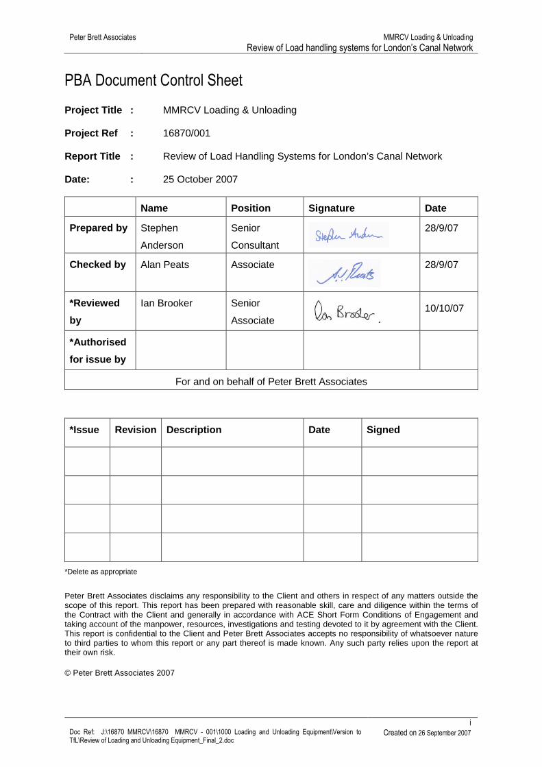
PBA Document Control Sheet
Project Title : MMRCV Loading & Unloading Project Ref : 16870/001 Report Title : Review of Load Handling Systems for London’s Canal Network Date: : 25 October 2007
Name Position Signature Date
Prepared by Stephen
Anderson
Senior
Consultant
28/9/07
Checked by Alan Peats Associate
28/9/07
*Reviewed
by
Ian Brooker Senior
Associate
10/10/07
*Authorised
for issue by
For and on behalf of Peter Brett Associates
*Issue Revision Description Date Signed
*Delete as appropriate
Peter Brett Associates disclaims any responsibility to the Client and others in respect of any matters outside the scope of this report. This report has been prepared with reasonable skill, care and diligence within the terms of the Contract with the Client and generally in accordance with ACE Short Form Conditions of Engagement and taking account of the manpower, resources, investigations and testing devoted to it by agreement with the Client. This report is confidential to the Client and Peter Brett Associates accepts no responsibility of whatsoever nature to third parties to whom this report or any part thereof is made known. Any such party relies upon the report at their own risk.
Peter Brett Associates MMRCV Loading & Unloading Review of Load handling systems for London’s Canal Network
iii Doc Ref: J:\16870 MMRCV\16870 MMRCV - 001\1000 Loading and Unloading Equipment\Version to TfL\Review of Loading and Unloading Equipment_Final_2.doc
Created on 26 September 2007
LIST OF FIGURES
Figure 1: Tugs and dumb barges used on London’s canals ....................................................................7 Figure 2: Self-propelled barges ..............................................................................................................10 Figure 3: Smart Barge units moving on the River Lee Navigation .........................................................12 Figure 4: Smart Barge units having skips unloaded...............................................................................13 Figure 5: TEU sized containers being loaded onto waste barges on the Thames.................................14 Figure 6: Waste containers on specially design barge on River Lee Navigation ...................................15 Figure 7: Methods of handling bulk materials on and off barges ...........................................................19 Figure 8: Transferring a skip to a barge using a skip lorry .....................................................................23 Figure 9: 32 tonnes hooklift vehicle........................................................................................................25 Figure 10: Wheeled crane used for lifting canal boats at a GUC boatyard............................................26 Figure 11: Crawler crane unloading sand at a Thames wharf ...............................................................27 Figure 12: Large mobile port crane ........................................................................................................27 Figure 13: Tracked cranes at Nurnberg inland port ...............................................................................29 Figure 14: Examples of disused fixed cranes on the Lee Navigation ....................................................30 Figure 15: Barge fitted with telescopic crane .........................................................................................32 Figure 16: Example of lorry mounted telescopic crane working.............................................................32 Figure 17: Barge mounted excavator crane ...........................................................................................33 Figure 18: Reach stacker loading a barge .............................................................................................34 Figure 19: Container on Containerlift vehicle .........................................................................................36 Figure 20: Container being unloaded from Containerlift vehicle ............................................................36 Figure 21: Smugglers Way gantry crane................................................................................................37 Figure 22: Forklift hoist used to unload/load barges ..............................................................................39
Peter Brett Associates MMRCV Loading & Unloading Review of Load handling systems for London’s Canal Network
iv Doc Ref: J:\16870 MMRCV\16870 MMRCV - 001\1000 Loading and Unloading Equipment\Version to TfL\Review of Loading and Unloading Equipment_Final_2.doc
Created on 26 September 2007
LIST OF TABLES
Table 2-1: Maximum craft dimensions for use on London section of Grand Union Canal.......................5 Table 2-2: Maximum craft dimensions for use on other London canals ..................................................6 Table 2-3: Dumb barges & push tugs.......................................................................................................7 Table 2-4: Self-propelled vessels .............................................................................................................9 Table 2-5: Containers with built-in flotation ............................................................................................11 Table 2-6: Floating skip rafts ..................................................................................................................12 Table 2-7: ISO Container sizes ..............................................................................................................13 Table 3-1: Handling bulk loads...............................................................................................................18 Table 3-2: Types of large containers......................................................................................................19 Table 3-3: Large individual loads ...........................................................................................................21 Table 3-4: Types of small unit loads.......................................................................................................21 Table 3-5: Skips......................................................................................................................................23 Table 3-6: Hooklifts.................................................................................................................................24 Table 3-7: Mobile land cranes ................................................................................................................26 Table 3-8: Fixed land cranes..................................................................................................................28 Table 3-9: Vessel mounted hoists ..........................................................................................................31 Table 3-10: Container lifting vehicles .....................................................................................................34 Table 3-11: Vehicle Based Container Handling Systems ......................................................................35 Table 3-12: Gantry cranes......................................................................................................................37 Table 5-1: Summary of key characteristics of handling systems ...........................................................44
Peter Brett Associates MMRCV Loading & Unloading Review of Load handling systems for London’s Canal Network
1 Doc Ref: J:\16870 MMRCV\16870 MMRCV - 001\1000 Loading and Unloading Equipment\Version to TfL\Review of Loading and Unloading Equipment_Final_2.doc
Created on 26 September 2007
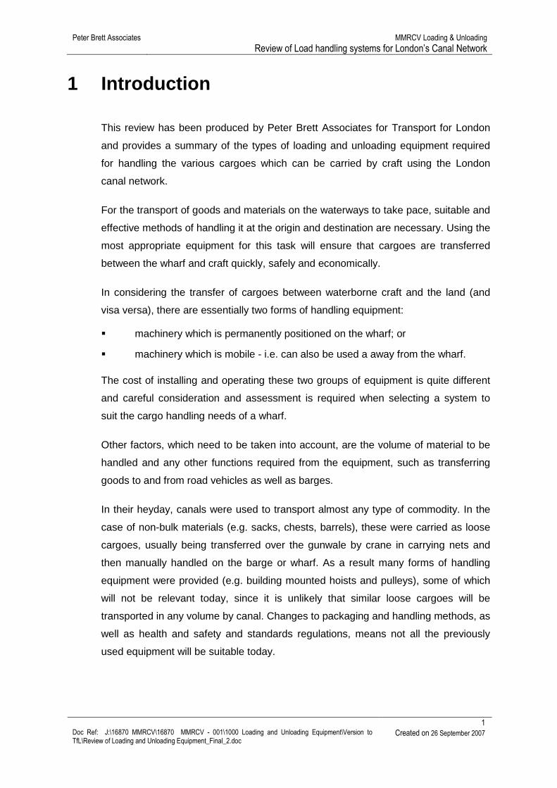
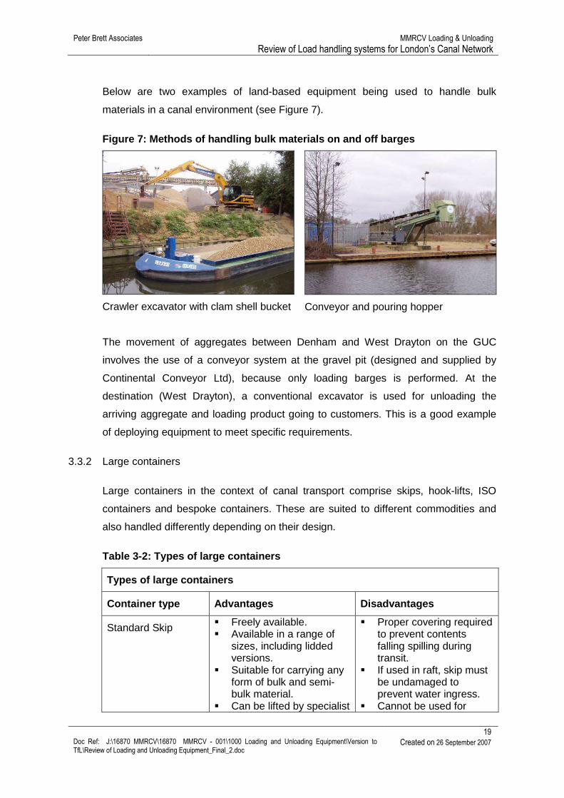
1 Introduction
This review has been produced by Peter Brett Associates for Transport for London
and provides a summary of the types of loading and unloading equipment required
for handling the various cargoes which can be carried by craft using the London
canal network.
For the transport of goods and materials on the waterways to take pace, suitable and
effective methods of handling it at the origin and destination are necessary. Using the
most appropriate equipment for this task will ensure that cargoes are transferred
between the wharf and craft quickly, safely and economically.
In considering the transfer of cargoes between waterborne craft and the land (and
visa versa), there are essentially two forms of handling equipment:
� machinery which is permanently positioned on the wharf; or
� machinery which is mobile - i.e. can also be used a away from the wharf.
The cost of installing and operating these two groups of equipment is quite different
and careful consideration and assessment is required when selecting a system to
suit the cargo handling needs of a wharf.
Other factors, which need to be taken into account, are the volume of material to be
handled and any other functions required from the equipment, such as transferring
goods to and from road vehicles as well as barges.
In their heyday, canals were used to transport almost any type of commodity. In the
case of non-bulk materials (e.g. sacks, chests, barrels), these were carried as loose
cargoes, usually being transferred over the gunwale by crane in carrying nets and
then manually handled on the barge or wharf. As a result many forms of handling
equipment were provided (e.g. building mounted hoists and pulleys), some of which
will not be relevant today, since it is unlikely that similar loose cargoes will be
transported in any volume by canal. Changes to packaging and handling methods, as
well as health and safety and standards regulations, means not all the previously
used equipment will be suitable today.
Peter Brett Associates MMRCV Loading & Unloading Review of Load handling systems for London’s Canal Network
2 Doc Ref: J:\16870 MMRCV\16870 MMRCV - 001\1000 Loading and Unloading Equipment\Version to TfL\Review of Loading and Unloading Equipment_Final_2.doc
Created on 26 September 2007
1.1 Canal use in London
All of London’s usable canals are situated north of the Thames, with the main access
points between the two waterway networks found at Brentwood, Limehouse Basin
and Bow Creek. However, very little, if any freight, currently moves from one water
system to the other.
The levels of freight carried exclusively on the canals (i.e. Grand Union Main Line,
Regents Canal, Paddington Arm, Slough Arm, Hertford Union and Lee Navigation)
into and out of, and within London are very small.
The most important waterway route in London (in terms of tonnes lifted) is the River
Thames, with 1.81 million tonnes of freight carried by water transport, in 2005. A key
factor for this position extends directly from the fact that the Thames has many
sources and destinations from and to which freight can be moved. On the lower
Thames a range of products are available for barging including aggregates, timber
and steel. Waste can also be transported downstream to disposal points in Essex.
With respect to London’s canals, their use for freight transport is so negligible that no
separate data are included in published national statistics - i.e. Waterborne Freight in
the United Kingdom 2005. Furthermore, information is not readily available, because
data regarding tonnages lifted and moved does not appear to be systematically
collected.
The largest regular flow of freight on London’s canals is the aggregates movement
from Denham to West Drayton (Harleyford Aggregates to Hanson), which has
planned traffic of 60,000 tonnes per annum, but is at present below this target at
around 50,000t per annum. Other movements of freight are more ad hoc, and include
traffic such as the transport of waste paper from Paddington Basin to Rickmansworth
and other construction waste and materials.
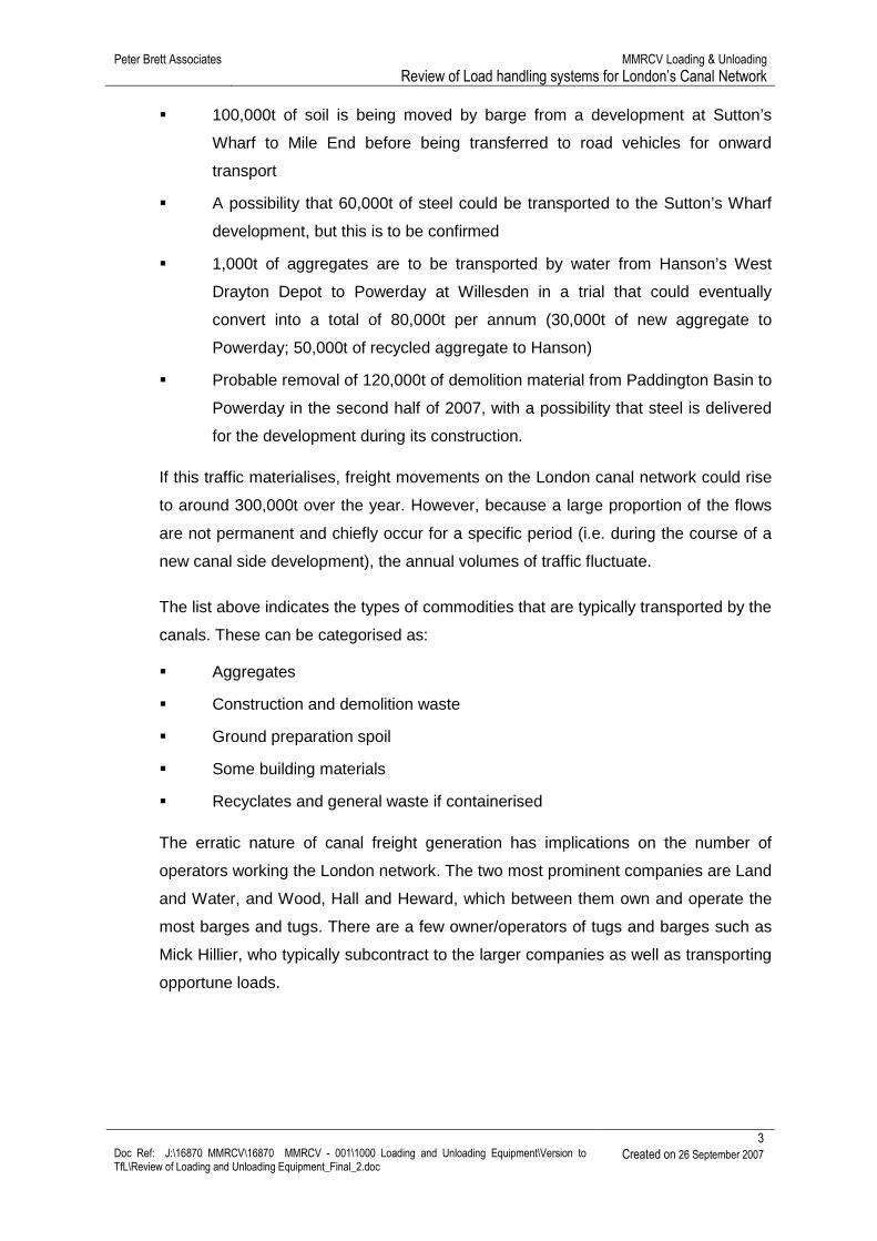
Although the quantity of freight moving on London’s canals during 2005 is estimated
by PBA to be no more 75,000t, a range of new traffic has either started or is
predicted to move shortly. These include:
� 10,000t of steel is being transported by water to the Kings Place development
taking place at Battlebridge Basin
Peter Brett Associates MMRCV Loading & Unloading Review of Load handling systems for London’s Canal Network
3 Doc Ref: J:\16870 MMRCV\16870 MMRCV - 001\1000 Loading and Unloading Equipment\Version to TfL\Review of Loading and Unloading Equipment_Final_2.doc
Created on 26 September 2007
� 100,000t of soil is being moved by barge from a development at Sutton’s
Wharf to Mile End before being transferred to road vehicles for onward
transport
� A possibility that 60,000t of steel could be transported to the Sutton’s Wharf
development, but this is to be confirmed
� 1,000t of aggregates are to be transported by water from Hanson’s West
Drayton Depot to Powerday at Willesden in a trial that could eventually
convert into a total of 80,000t per annum (30,000t of new aggregate to
Powerday; 50,000t of recycled aggregate to Hanson)
� Probable removal of 120,000t of demolition material from Paddington Basin to
Powerday in the second half of 2007, with a possibility that steel is delivered
for the development during its construction.
If this traffic materialises, freight movements on the London canal network could rise
to around 300,000t over the year. However, because a large proportion of the flows
are not permanent and chiefly occur for a specific period (i.e. during the course of a
new canal side development), the annual volumes of traffic fluctuate.
The list above indicates the types of commodities that are typically transported by the
canals. These can be categorised as:
� Aggregates
� Construction and demolition waste
� Ground preparation spoil
� Some building materials
� Recyclates and general waste if containerised
The erratic nature of canal freight generation has implications on the number of
operators working the London network. The two most prominent companies are Land
and Water, and Wood, Hall and Heward, which between them own and operate the
most barges and tugs. There are a few owner/operators of tugs and barges such as
Mick Hillier, who typically subcontract to the larger companies as well as transporting
opportune loads.
Peter Brett Associates MMRCV Loading & Unloading Review of Load handling systems for London’s Canal Network
4 Doc Ref: J:\16870 MMRCV\16870 MMRCV - 001\1000 Loading and Unloading Equipment\Version to TfL\Review of Loading and Unloading Equipment_Final_2.doc
Created on 26 September 2007
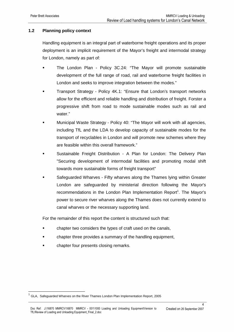
1.2 Planning policy context
Handling equipment is an integral part of waterborne freight operations and its proper
deployment is an implicit requirement of the Mayor’s freight and intermodal strategy
for London, namely as part of:
� The London Plan - Policy 3C.24: “The Mayor will promote sustainable
development of the full range of road, rail and waterborne freight facilities in
London and seeks to improve integration between the modes.”
� Transport Strategy - Policy 4K.1: “Ensure that London’s transport networks
allow for the efficient and reliable handling and distribution of freight. Forster a
progressive shift from road to mode sustainable modes such as rail and
water.”
� Municipal Waste Strategy - Policy 40: “The Mayor will work with all agencies,
including TfL and the LDA to develop capacity of sustainable modes for the
transport of recyclables in London and will promote new schemes where they
are feasible within this overall framework.”
� Sustainable Freight Distribution - A Plan for London: The Delivery Plan
"Securing development of intermodal facilities and promoting modal shift
towards more sustainable forms of freight transport"
� Safeguarded Wharves - Fifty wharves along the Thames lying within Greater
London are safeguarded by ministerial direction following the Mayor's
recommendations in the London Plan Implementation Report1. The Mayor's
power to secure river wharves along the Thames does not currently extend to
canal wharves or the necessary supporting land.
For the remainder of this report the content is structured such that:
� chapter two considers the types of craft used on the canals,
� chapter three provides a summary of the handling equipment,
� chapter four presents closing remarks.
1 GLA, Safeguarded Wharves on the River Thames London Plan Implementation Report, 2005
Peter Brett Associates MMRCV Loading & Unloading Review of Load handling systems for London’s Canal Network
5 Doc Ref: J:\16870 MMRCV\16870 MMRCV - 001\1000 Loading and Unloading Equipment\Version to TfL\Review of Loading and Unloading Equipment_Final_2.doc
Created on 26 September 2007
2 Types of vessel
2.1 Introduction
In order to consider the methods for handling freight on and off of barges and craft
that use the canals, it is helpful to have an overview of the types of vessels that are
used to carry freight by water.
2.2 Background
For craft to move efficiently and safely on the waterways they have to be designed to
work within the physical parameters of the infrastructure. Essentially these
parameters can be considered as relating to factors affecting:
� their movement; and
� their loading and unloading.
Within London the different sections of the Grand Union Canal’s infrastructure
conform to the same dimensions. This is an important factor since it permits vessel
design and configuration to be optimised such that the craft can be built to maximise
their permissible capacity and therefore offer the best commercial option for freight
movement within the working environment. The key causes that constrain the
dimensions of craft include the size of locks, bridges, tunnels, turning requirements
and radii of bends.
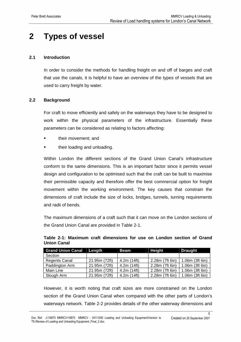
The maximum dimensions of a craft such that it can move on the London sections of
the Grand Union Canal are provided in Table 2-1.
Table 2-1: Maximum craft dimensions for use on Lond on section of Grand Union Canal
Grand Union Canal Length Beam Height Draught Section Regents Canal 21.95m (72ft) 4.2m (14ft) 2.28m (7ft 6in) 1.06m (3ft 6in) Paddington Arm 21.95m (72ft) 4.2m (14ft) 2.28m (7ft 6in) 1.06m (3ft 6in) Main Line 21.95m (72ft) 4.2m (14ft) 2.28m (7ft 6in) 1.06m (3ft 6in) Slough Arm 21.95m (72ft) 4.2m (14ft) 2.28m (7ft 6in) 1.06m (3ft 6in)
However, it is worth noting that craft sizes are more constrained on the London
section of the Grand Union Canal when compared with the other parts of London’s
waterways network. Table 2-2 provides details of the other waterway dimensions and
Peter Brett Associates MMRCV Loading & Unloading Review of Load handling systems for London’s Canal Network
6 Doc Ref: J:\16870 MMRCV\16870 MMRCV - 001\1000 Loading and Unloading Equipment\Version to TfL\Review of Loading and Unloading Equipment_Final_2.doc
Created on 26 September 2007
indicates that craft designed for the Grand Union Canal can be easily accommodated
on the other waterways.
Table 2-2: Maximum craft dimensions for use on othe r London canals
Other Canals Length Beam Height Draught
Hertford Union (Grand Union Canal) 21.95m (72ft) 4.2m (14ft) 2.28m (7ft 6in) 1.06m (3ft 6in)
Lee Navigation - Thames/Old Ford 26.82m (88ft) 5.8m (19ft) 2.05m (6ft 9in) 2.05m (6ft 9in)
Lee Navigation - Old Ford/Ponders End 26.82m (88ft) 5.5m (18ft) 2.05m (6ft 9in) 1.06m (3ft 6in)
The implications of having different canal infrastructure dimensions means that craft
designed to navigate the Lee Navigation are unable to enter the Grand Union Canal
(GUC), although the smaller craft of the GUC are able to operate on the Lee. In
terms of capacity, a Lee Navigation craft can carry up to 120 tonnes of cargo, while
GUC vessels are limited to about 80 tonnes. There are also implications if the
carriage of containerised freight is being considered.
Although certain infrastructure features limit craft dimensions in terms of their
movement along waterways, canalside mooring can also have a bearing on vessel
size. On-going canalside development has resulted in the depletion of commercial
wharves and in some areas has led to the removal of continuous stretches of wharf
at which freight vessels can moor.
Vessel design also needs to take account of the loading and unloading methods at
wharves, as these will impact upon factors such as the size of hatch openings,
internal vessel construction or whether it should be self-propelled or a ‘dumb’ unit.
2.3 Vessel design
Vessels designed to carry freight on canals should aim to satisfy the following
elements:
� maximise the capacity of the vessel within the limits of canal dimensions,
� facilitate loading and unloading methods,
� ensure protection for the cargoes, and
� maintain the performance / handling of the vessels (BWS, 2006).
It is noted in the Lowland Canals Freight Action Plan Report, that, “The ideal shape
of a vessel to maximise the carrying capacity is a rectangle. However the optimum
Peter Brett Associates MMRCV Loading & Unloading Review of Load handling systems for London’s Canal Network
7 Doc Ref: J:\16870 MMRCV\16870 MMRCV - 001\1000 Loading and Unloading Equipment\Version to TfL\Review of Loading and Unloading Equipment_Final_2.doc
Created on 26 September 2007
shape for vessel handling is smoothly curved, pointed at the front and rounded at the
rear (boat shaped!). Vessel design therefore has to be a trade-off in hull design
between maximum capacity and maximum performance.” (BWS, 2006)
Various vessel configurations are available for use on inland waterways, which can
be considered under the flowing headings:
� Dumb barges and tugs.
� Self-propelled craft.
� Containers with built-in flotation.
� Floating skip rafts.
� Container carriers.
2.3.1 Dumb barges and tugs
This type of barge is a non-motorised barge which needs to be pushed or pulled by a
motorised tug. Constructed of steel, ideally the hull should be double skinned or built
to a design that dispenses with the need for internal cross-hull bracing (e.g. chains or
bulkheads). This type of vessel is commonly used for a wide range of cargoes which
are both bulk and general purpose and can be moved more than one at a time since
they can be lashed together in tandem.
The tugs are a separate motorised unit capable of pushing and/or pulling dumb
barges. This may be carried out in various configurations - e.g. a tug pulling one or
two barges, a tug pushing one barge, a tug pushing one barge and pulling one or
two, with a helmsman steering the rear barge. Table 2-3 summarises the key
features, while Figure 1 shows examples of the vessels.
Table 2-3: Dumb barges & push tugs
Dumb barges Advantages
� Cheap to construct. � Can have multiple barges and, where relevant for freight type,
multiple sets of containers. � Can be stored at suitable lay-byes or wide areas. � Large loads can be cheaply transported along longer pounds
using one tug working more than one barge. � Removes reliance on ‘winding holes’ (turning points) and
thereby reduce the journey times.
Disadvantages
� Handling – dumb barges need extra handling to pass through locks etc. For practical purposes, it might be necessary to assign a tug to each barge down flights of locks.
Peter Brett Associates MMRCV Loading & Unloading Review of Load handling systems for London’s Canal Network
8 Doc Ref: J:\16870 MMRCV\16870 MMRCV - 001\1000 Loading and Unloading Equipment\Version to TfL\Review of Loading and Unloading Equipment_Final_2.doc
Created on 26 September 2007
� There are practical & safety considerations that might preclude the use of towlines - the use of long towlines has safety implications for other canal users. However, use of a push-tug pushing one barge and towing another one or two is a possibility, particularly if towlines are short.
� Lack of available modern designs and new builds.
Push tugs Advantages
� Relatively cheap to construct compared with motorised barges.
� Capable of moving single or multiple barge units, offering larger tonnage movement each trip.
� Can be used for shunting operations at wharf if a number of barges moored.
� Fully flexible - can be used for moving any type of cargo. Disadvantages
� Require two crew members if used to haul more than one barge.
� Unable to enter lock along with barge due over length of tow. � Where a barge fills the lock tugs are unable to
Source: Adapted from BWS, 2005
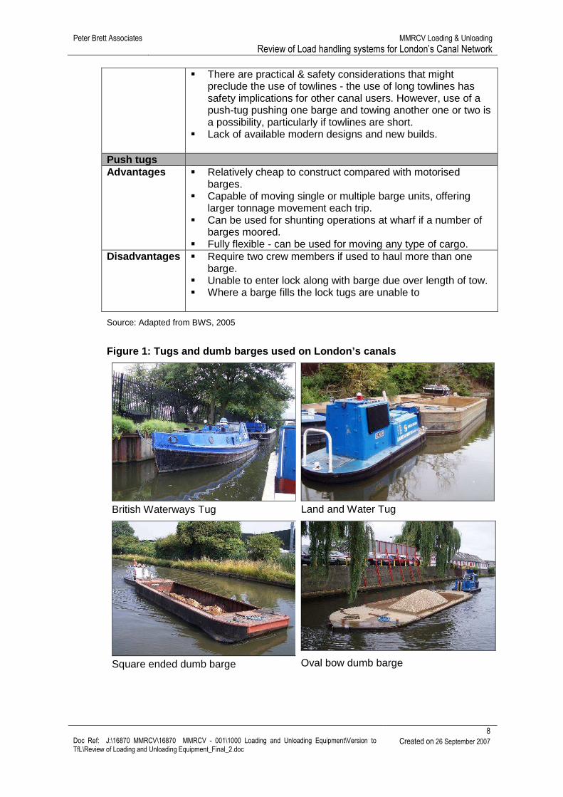
Figure 1: Tugs and dumb barges used on London’s can als
British Waterways Tug
Land and Water Tug
Square ended dumb barge
Oval bow dumb barge
Peter Brett Associates MMRCV Loading & Unloading Review of Load handling systems for London’s Canal Network
9 Doc Ref: J:\16870 MMRCV\16870 MMRCV - 001\1000 Loading and Unloading Equipment\Version to TfL\Review of Loading and Unloading Equipment_Final_2.doc
Created on 26 September 2007
The cost of procuring and operating tugs and barges of this nature depends on the
exact specification, but typically they might be in the order of:
Tug: Purchase cost: Maintenance cost: Fuel costs at 6 lt per hour: 2 x Literman at £24,000: Total yearly outlay including purchase: Yearly outlay thereafter:
£40,000 £3,000 £19,500 a year £48,000 £110,842 £70,500
Dumb barge: Purchase cost: Maintenance cost: Total yearly outlay including Purchase: Yearly outlay thereafter:
£10,500 £500 £11,000 £500
2.3.2 Self-propelled craft
This type of barge is motorised comprising an engine at the rear of the vessel and a
large hold area in the remainder. It has a crew of one or two people and can pass
through locks in a single cycle. These vessels are able to carry a variety of cargoes
and can be designed to include a ‘tanked’ hold to carry bulk powders (e.g. cement) or
liquids. Table 2-4 summarises the key features, while Figure 2 shows examples of
the vessels.
Table 2-4: Self-propelled vessels
Self-propelled vessels
Advantages � Manoeuvred under own power, so no roping needed. � Self contained so no problems involving towing. � Multi-purpose – can be used for different cargoes.
Disadvantages � Expensive to build, so need to be operating as many hours as possible to get return on investment.
� Need more than one to handle most potential traffic types, so more capital outlay is required to move large quantities of freight.
Peter Brett Associates MMRCV Loading & Unloading Review of Load handling systems for London’s Canal Network
10 Doc Ref: J:\16870 MMRCV\16870 MMRCV - 001\1000 Loading and Unloading Equipment\Version to TfL\Review of Loading and Unloading Equipment_Final_2.doc
Created on 26 September 2007
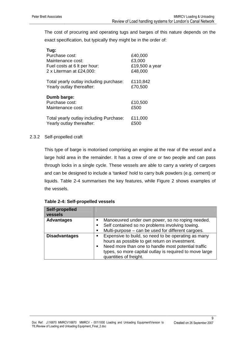
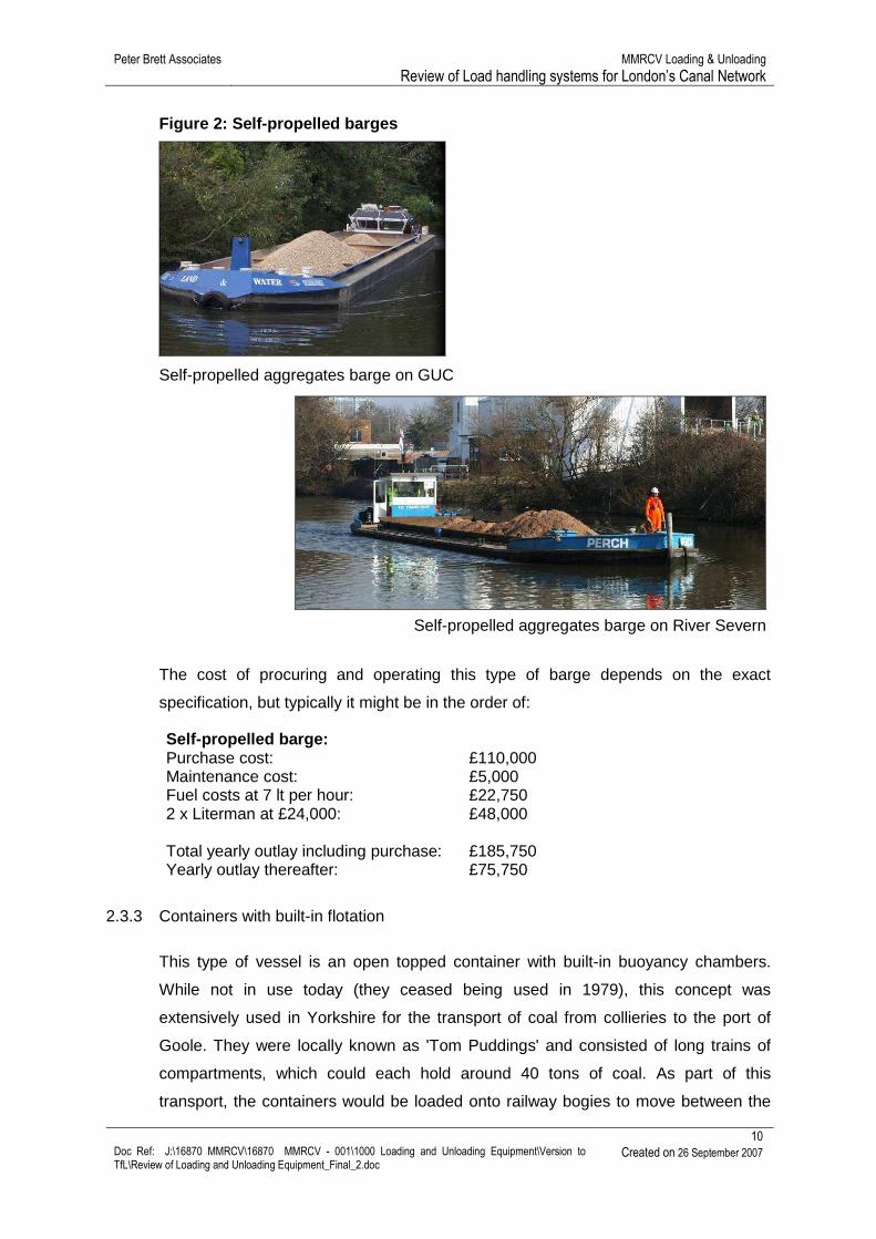
Figure 2: Self-propelled barges
Self-propelled aggregates barge on GUC
Self-propelled aggregates barge on River Severn
The cost of procuring and operating this type of barge depends on the exact
specification, but typically it might be in the order of:
Self-propelled barge: Purchase cost: Maintenance cost: Fuel costs at 7 lt per hour: 2 x Literman at £24,000: Total yearly outlay including purchase: Yearly outlay thereafter:
£110,000 £5,000 £22,750 £48,000 £185,750 £75,750
2.3.3 Containers with built-in flotation
This type of vessel is an open topped container with built-in buoyancy chambers.
While not in use today (they ceased being used in 1979), this concept was
extensively used in Yorkshire for the transport of coal from collieries to the port of
Goole. They were locally known as 'Tom Puddings' and consisted of long trains of
compartments, which could each hold around 40 tons of coal. As part of this
transport, the containers would be loaded onto railway bogies to move between the
Peter Brett Associates MMRCV Loading & Unloading Review of Load handling systems for London’s Canal Network
11 Doc Ref: J:\16870 MMRCV\16870 MMRCV - 001\1000 Loading and Unloading Equipment\Version to TfL\Review of Loading and Unloading Equipment_Final_2.doc
Created on 26 September 2007
colliery and canal, providing a unique intermodal transfer system. To empty the
containers at Goole, each unit was hoisted from the water by special lifting gear and
tipped. (Goole, 2007) Table 2-5 summarises the key features.
Table 2-5: Containers with built-in flotation
“Tom Pudding” type vessels / Containers with built-in flotation
Advantages � Make up loads steadily, with spare empties. � Can store at locations along the canals to await onward
passage. � Cheap to construct. � Large loads can be bulked together and quickly and
easily transported along longer lock-free stretches of canals.
� Containers can be lifted and emptied away from the canal.
Disadvantages � Each individual “pan” is likely to have different loads - trimming each container to form a tow could be time consuming.
� Would need extra handling to work them through locks. � For practical purposes, each configuration would need a
separate tug to work the flights of locks. � There are practical & safety considerations that might
preclude the use of long towlines.
Source: Adapted from BWS, 2005
2.3.4 Floating skip rafts
This type of equipment permits conventional builders’ skips to be transported on
water by sitting in a buoyant raft framework. The ‘Pond Skater’, which is now known
as Smart Barge (see Table 2-6), is designed to be loaded from a standard skip lorry.
Once loaded, a number of skips can be towed in tandem behind a tug. It is assumed
that more than one empty skip can be returned in a single trip due to the ability to
‘stack’ empty skips. (STRAW, 2005) This form of equipment is untested commercially
and trial are planned to test its operational and commercial viability (See
Figure 3 and Figure 4).
Peter Brett Associates MMRCV Loading & Unloading Review of Load handling systems for London’s Canal Network
12 Doc Ref: J:\16870 MMRCV\16870 MMRCV - 001\1000 Loading and Unloading Equipment\Version to TfL\Review of Loading and Unloading Equipment_Final_2.doc
Created on 26 September 2007
Table 2-6: Floating skip rafts
“Pond Skater” - Floating skip rafts
Advantages � Can use standard skip equipment. � Generally, can be loaded straight from standard skip
lorry. � Cheap to build and readily available � Can be lifted from water by basic crane or standard
skip lorry. � Can be loaded away from water and moved along
side canal when full. Disadvantages � Limited payload - largest skips carry about 9 cubic
metres of material � Skips must be in perfect condition and seam welding
has to be to a high standard to prevent water ingress. � Require load bearing wharf to water’s edge at correct
height. � In some locations the skip lorry might require
extending lifting arms.
Source: Adapted from BWS, 2005
Figure 3: Smart Barge units moving on the River Lee Navigation
Source: London Remade, 2007
Peter Brett Associates MMRCV Loading & Unloading Review of Load handling systems for London’s Canal Network
13 Doc Ref: J:\16870 MMRCV\16870 MMRCV - 001\1000 Loading and Unloading Equipment\Version to TfL\Review of Loading and Unloading Equipment_Final_2.doc
Created on 26 September 2007
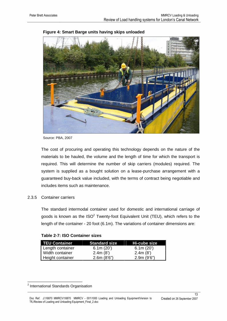
Figure 4: Smart Barge units having skips unloaded
Source: PBA, 2007
The cost of procuring and operating this technology depends on the nature of the
materials to be hauled, the volume and the length of time for which the transport is
required. This will determine the number of skip carriers (modules) required. The
system is supplied as a bought solution on a lease-purchase arrangement with a
guaranteed buy-back value included, with the terms of contract being negotiable and
includes items such as maintenance.
2.3.5 Container carriers
The standard intermodal container used for domestic and international carriage of
goods is known as the ISO2 Twenty-foot Equivalent Unit (TEU), which refers to the
length of the container - 20 foot (6.1m). The variations of container dimensions are:
The Waste on Water trial demonstrated that this type of technology is useable in an
intermodal environment. However, it is necessary that the barges used for
transporting hooklift containers are fitted with a suitable sub-frame such that they can
be loaded/unloaded and carried by the craft. This is necessary because the container
is lifted at the front while moved backwards or forwards on roller fitted to the rear of
its base. Furthermore, this push/pull movement of the container during transfer
requires the barge to be fitted with retractable stabilising legs (‘spud legs’) that sit on
the canal bed to preventing it from rolling. It should be noted that loading is only
possible across the beam of the barge, which means containers are limited to 4m in
length for GUC movements and 5m on the Lee Navigation. If a barge operator were
to purchase this equipment it would cost in the order of:
Hooklift loader: Hooklift suitable for 8x4 chassis at 32 tonnes GVW 25 tonnes lift capacity supplied and fitted: Suitable 32 tonne GVW vehicle:
£17,500 £54,500
3.3.3.3 Land cranes - wheeled / crawler
Land based wheeled and crawler cranes are general purpose equipment that can be
fitted with a variety of attachments for handling different materials and loads, and are
suitable for a wide range of lifting applications. This type of craneage is often used on
canal wharves, as it does not require any special installation (apart from an
appropriately strengthened wharf surface and edge), can be operated in relatively
small spaces and is easy to operate. Furthermore, this type of equipment is available
Peter Brett Associates MMRCV Loading & Unloading Review of Load handling systems for London’s Canal Network
26 Doc Ref: J:\16870 MMRCV\16870 MMRCV - 001\1000 Loading and Unloading Equipment\Version to TfL\Review of Loading and Unloading Equipment_Final_2.doc
Created on 26 September 2007
through short-term hire, long-term lease, as well as through a good second hand
market.
Table 3-7: Mobile land cranes
Methods for handling loads
Handling method Advantages Disadvantages
Land cranes -
wheeled / crawler
� Flexible method for craning as different attachments can be used - e.g. buckets, pallet forks, slings.
� Crane can be moved between wharves.
� Can be used for other uses on-site when not required at wharf.
� Cost attractive option because can be brought in for short term use.
� Good second hand market for this equipment.
� Needs suitable platform capable of withstanding point load of stabilisers.
� Needs sufficient space for manoeuvring and stabilisers.
� Requires qualified crane driver and slinger or container-grab.
Source: Adapted from BWS, 2005
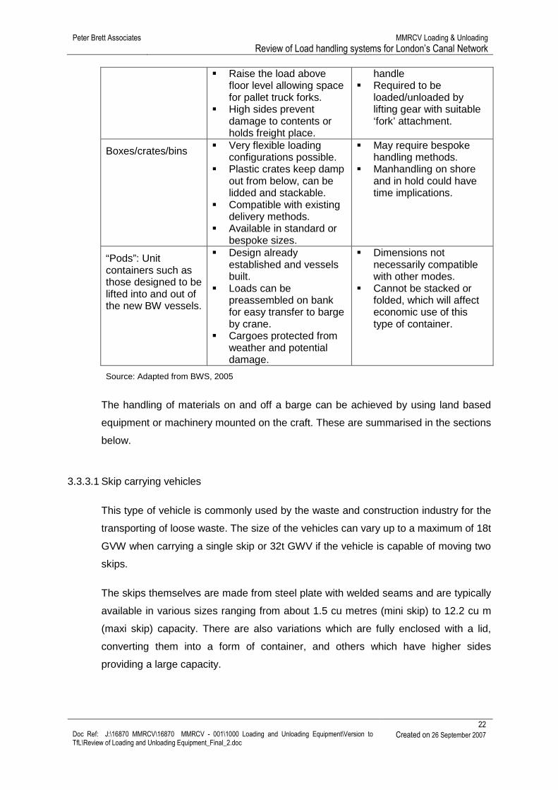
Figure 10: Wheeled crane used for lifting canal boa ts at a GUC boatyard
The equipment in Figure 10 demonstrates that is does no have to be the most
modern if it is not going to be used too intensively.
Peter Brett Associates MMRCV Loading & Unloading Review of Load handling systems for London’s Canal Network
27 Doc Ref: J:\16870 MMRCV\16870 MMRCV - 001\1000 Loading and Unloading Equipment\Version to TfL\Review of Loading and Unloading Equipment_Final_2.doc
Created on 26 September 2007
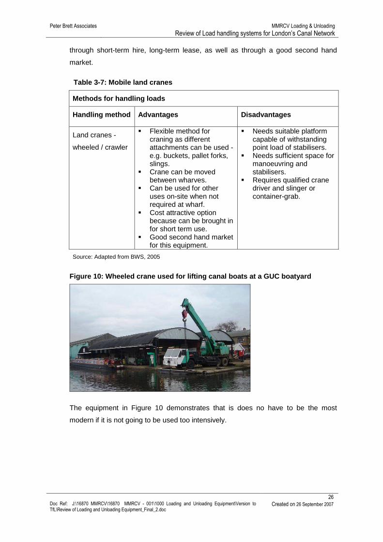
Figure 11: Crawler crane unloading sand at a Thames wharf
Figure 11 shows a good example of the extent of reach that this type of equipment
has, as it unloads sand on at a Thames side wharf.
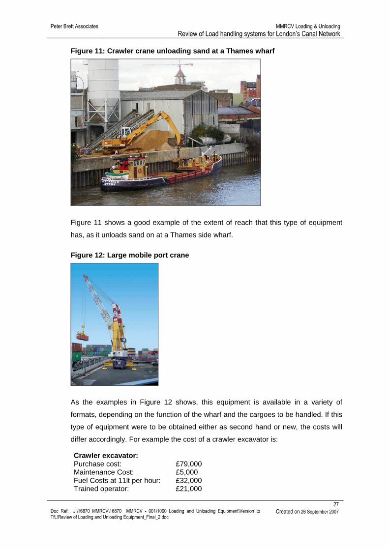
Figure 12: Large mobile port crane
As the examples in Figure 12 shows, this equipment is available in a variety of
formats, depending on the function of the wharf and the cargoes to be handled. If this
type of equipment were to be obtained either as second hand or new, the costs will
differ accordingly. For example the cost of a crawler excavator is:
Crawler excavator: Purchase cost: Maintenance Cost: Fuel Costs at 11lt per hour: Trained operator:
£79,000 £5,000 £32,000 £21,000
Peter Brett Associates MMRCV Loading & Unloading Review of Load handling systems for London’s Canal Network
28 Doc Ref: J:\16870 MMRCV\16870 MMRCV - 001\1000 Loading and Unloading Equipment\Version to TfL\Review of Loading and Unloading Equipment_Final_2.doc
Created on 26 September 2007
For large quayside cranes as show in the bottom example above, the costs could be:
Large mobile port crane: Purchase cost second hand for a 350 ton crane: Annual maintenance cost: Fuel costs at 12lt per hour: 2 x Drivers at£26,000: Total yearly outlay including purchase: Yearly outlay thereafter:
£623,500 £9,000 £37,000 £52,000 £721,000 £98,000
3.3.3.4 Land cranes - fixed / tracked
This type of equipment is typically located on wharves and quays serving larger
waterborne traffic (e.g. main river and sea ports, Rhine-Danube canal ports),
although disused examples can be found on the Lee Navigation. As the title implies,
this machinery is permanently located on the quay and can be permitted travel along
the quay using rails or completely static only working from the same point. In a
London context their installation will require substantial wharf improvements to take
place since no canals have the necessary strengthened bases in place.
Table 3-8: Fixed land cranes
Methods for handling loads
Handling
method
Advantages Disadvantages
Land cranes - fixed / tracked
� Capable of lifting heavy loads.
� If fixed, less space required.
� Only requires crane base area to be sufficiently load-bearing
� Crane permanently located at wharf.
� One crane per wharf required.
� Requires qualified crane driver and slinger or ISO container-grab.
� Expensive procurement costs.
� Requires high utilisation rate to be cost effective.
� May be issues of with wharf security if operating 24 hours a day.
Source: Adapted from BWS, 2005
Peter Brett Associates MMRCV Loading & Unloading Review of Load handling systems for London’s Canal Network
29 Doc Ref: J:\16870 MMRCV\16870 MMRCV - 001\1000 Loading and Unloading Equipment\Version to TfL\Review of Loading and Unloading Equipment_Final_2.doc
Created on 26 September 2007
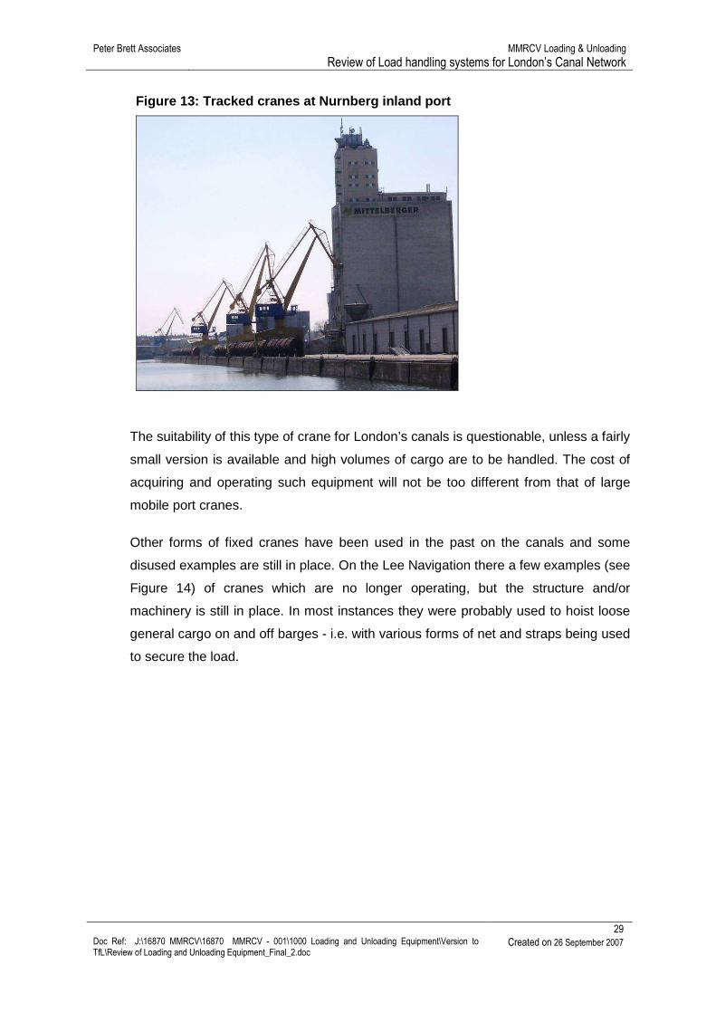
Figure 13: Tracked cranes at Nurnberg inland port
The suitability of this type of crane for London’s canals is questionable, unless a fairly
small version is available and high volumes of cargo are to be handled. The cost of
acquiring and operating such equipment will not be too different from that of large
mobile port cranes.
Other forms of fixed cranes have been used in the past on the canals and some
disused examples are still in place. On the Lee Navigation there a few examples (see
Figure 14) of cranes which are no longer operating, but the structure and/or
machinery is still in place. In most instances they were probably used to hoist loose
general cargo on and off barges - i.e. with various forms of net and straps being used
to secure the load.
Peter Brett Associates MMRCV Loading & Unloading Review of Load handling systems for London’s Canal Network
30 Doc Ref: J:\16870 MMRCV\16870 MMRCV - 001\1000 Loading and Unloading Equipment\Version to TfL\Review of Loading and Unloading Equipment_Final_2.doc
Created on 26 September 2007
Figure 14: Examples of disused fixed cranes on the Lee Navigation
Crane located adjacent to Ponder’s End Lock
Crane located on Watermint Quay
Peter Brett Associates MMRCV Loading & Unloading Review of Load handling systems for London’s Canal Network
31 Doc Ref: J:\16870 MMRCV\16870 MMRCV - 001\1000 Loading and Unloading Equipment\Version to TfL\Review of Loading and Unloading Equipment_Final_2.doc
Created on 26 September 2007
Grantry type cranes located on Watermint Quay
3.3.3.5 Vessel mounted cranes
The size of barges used on the London’s canals makes them suitable to being fitted
with telescopic cranes. This equipment uses hydraulics to operate its mechanism and
is commonly fitted to builders merchants lorries, construction lorries and brick
delivery vehicles. A variety of attachments can be fitted to the crane and when fitted
to a barge, permits it to be self sufficient for loading and unloading. Since these crane
use hydraulics to work, they do require the pump to be powered from a motor (i.e.
normal the vehicle motor on a lorry). This suggests that the crane needs to be
mounted on a self-propelled barge in order for the craft’s engine to drive the crane’s
hydraulics, although the possibility of fitting a crane and motor to a dumb barge
needs to be investigated.
Table 3-9: Vessel mounted hoists
Methods for handling loads
Handling method Advantages Disadvantages
Vessel mounted cranes
� Provides self-sufficient and flexible vessel.
� Can be used at any suitable canal side location.
� Can use hoists designed for mounting on goods vehicles.
� Can be used to
� Could limit vessel configuration and payload.
� Vessel might require stabilising legs to prevent roll.
� If used to unload/load alongside vessels, occupies mooring
Peter Brett Associates MMRCV Loading & Unloading Review of Load handling systems for London’s Canal Network
32 Doc Ref: J:\16870 MMRCV\16870 MMRCV - 001\1000 Loading and Unloading Equipment\Version to TfL\Review of Loading and Unloading Equipment_Final_2.doc
Created on 26 September 2007
unload/load other alongside vessels if fitted with suitable telescoping arm.
capacity.
Source: Adapted from BWS, 2005
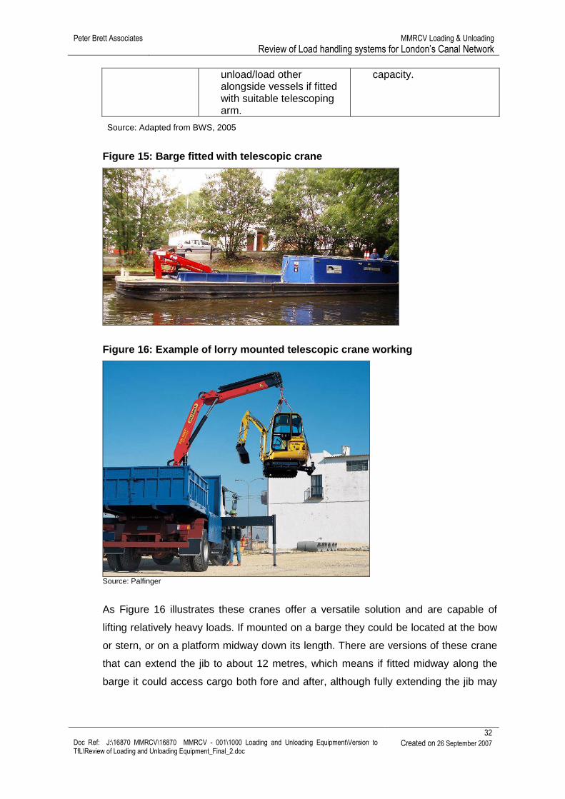
Figure 15: Barge fitted with telescopic crane
Figure 16: Example of lorry mounted telescopic cran e working
Source: Palfinger
As Figure 16 illustrates these cranes offer a versatile solution and are capable of
lifting relatively heavy loads. If mounted on a barge they could be located at the bow
or stern, or on a platform midway down its length. There are versions of these crane
that can extend the jib to about 12 metres, which means if fitted midway along the
barge it could access cargo both fore and after, although fully extending the jib may
Peter Brett Associates MMRCV Loading & Unloading Review of Load handling systems for London’s Canal Network
33 Doc Ref: J:\16870 MMRCV\16870 MMRCV - 001\1000 Loading and Unloading Equipment\Version to TfL\Review of Loading and Unloading Equipment_Final_2.doc
Created on 26 September 2007
have implications on the weight that can be lifted. Issues regarding barge stability
during use also need to be considered.
Other options including fitting the crane portion of an excavator to the hull of a self-
propelled barge, which can act as a floating craneage platform transferring loads
between barge and embankment at points where no suitable land-based wharf exist
(see Figure 17).
Figure 17: Barge mounted excavator crane
The example in Figure 17 is of a British Waterways’ barge that is used for dredging
and rubbish clearance of the canal and is moored on the Lee Navigation.
3.3.3.6 Container reach-stackers
Reach stackers are designed to do what they say, reach and stack. Equipped with a
telescopic jib, they can reach out over the water and lift a container from some
distance away. However, in situations where the use of a long jib is required, a more
expensive and heavy the reach stacker is needed. Once lifted, they can carry the
container around the yard if required, making these machines extremely flexible.
In Continental inland waterway ports, they are commonly used for the barge to shore
cargo handling and would be reasonably cost effective solution for most high volume
canal side container lifting operations.
One of the main considerations in deploying this type of equipment is the strength of
the wharf, which has to be built to a standard which can cope with the weight of these
machines. In a railway yard, a reinforced concrete pavement is generally specified,
such that the slab is in the order of 300 mm thick for the most part and 400 mm thick
at the edge, (i.e. where the railway lines are), because this is where the stacker does
its lifting and consequently throws almost all its weight onto its front axle. Due to this
Peter Brett Associates MMRCV Loading & Unloading Review of Load handling systems for London’s Canal Network
34 Doc Ref: J:\16870 MMRCV\16870 MMRCV - 001\1000 Loading and Unloading Equipment\Version to TfL\Review of Loading and Unloading Equipment_Final_2.doc
Created on 26 September 2007
requirement and the high capital cost of reach stackers, they are generally preferred
where throughput volumes are high and where flexibility is required.
Table 3-10: Container lifting vehicles
Methods for handling loads
Handling method Advantages Disadvantages
Container reach-stackers
� Designed to handle standard containers flexibly & efficiently.
� Only requires one man to operate.
� Can be moved between wharves.
� Can be used to move containers when not required for vessel loading/unloading.
� Requires load-bearing wharf to water’s edge.
� Expensive to buy. � May be issues of with
wharf security if operating 24 hours a day.
� Requires high utilisation rate to be cost effective.
Source: Adapted from BWS, 2005
Figure 18: Reach stacker loading a barge
This type of machinery is able to handle 1 container about every 3 minutes and is
capable of working in relatively small areas due to its good turning circle and ability to
swivel a container held in the spreader. This means a single reach stacker could be
operated on fairly constrained wharves, which are typical of the type found on the
London canal network.
Reach stacker: Indicative costs for procuring and running a reach
Peter Brett Associates MMRCV Loading & Unloading Review of Load handling systems for London’s Canal Network
35 Doc Ref: J:\16870 MMRCV\16870 MMRCV - 001\1000 Loading and Unloading Equipment\Version to TfL\Review of Loading and Unloading Equipment_Final_2.doc
Created on 26 September 2007
stacker: Purchase cost: Maintenance cost at £9.50p/h: Fuel costs at 11lt per hour: Trained operator: Reinforcement of Pier: Total yearly outlay including purchase: Yearly outlay thereafter
3.3.3.7 Goods Vehicle Based Container Handling Systems
Recently a new category of handling system has been developed which allows the
transfer of containers between vehicles using equipment mounted on the road
vehicle. The most widespread system in use in the UK is Containerlift, which involves
a crane mounted on a road vehicle which can transfer containers to other vehicles or
to the ground. When not being used as a crane the vehicle can be used to transport
containers in the normal way.
Table 3-11: Vehicle Based Container Handling System s
Methods for handling loads
Handling method Advantages Disadvantages
Vehicle based container handling systems
� Designed to handle standard containers efficiently.
� Requires only one man to operate.
� Vehicle and driver can transport containers or move to different locations.
� Low investment cost, little or no site preparation required.
� Specialist operators and maintenance requirements.
� Only suitable for container lifts.
Source: Meeting with Containerlift 7/11/2005
Peter Brett Associates MMRCV Loading & Unloading Review of Load handling systems for London’s Canal Network
36 Doc Ref: J:\16870 MMRCV\16870 MMRCV - 001\1000 Loading and Unloading Equipment\Version to TfL\Review of Loading and Unloading Equipment_Final_2.doc
Created on 26 September 2007
Figure 19: Container on Containerlift vehicle
Figure 20: Container being unloaded from Containerl ift vehicle
When used for transferring container to/from barges the crane arms can be
extended, permitting the equipment to reach over the centre of the craft. However,
due to its configuration on the vehicle, this equipment can only place/lift containers
which are lengthwise in the barge.
Containerlift: Indicative costs for procuring and running a Containerlift vehicle: Purchase cost: Maintenance cost (estimate): Trained operator: Reinforcement of Pier: Total yearly outlay including purchase: Yearly outlay thereafter
� Specialist operators and maintenance requirements.
� Only suitable for container lifts.
� Requires very high utilisation rate to be cost effective.
Source: Adapted from BWS, 2005
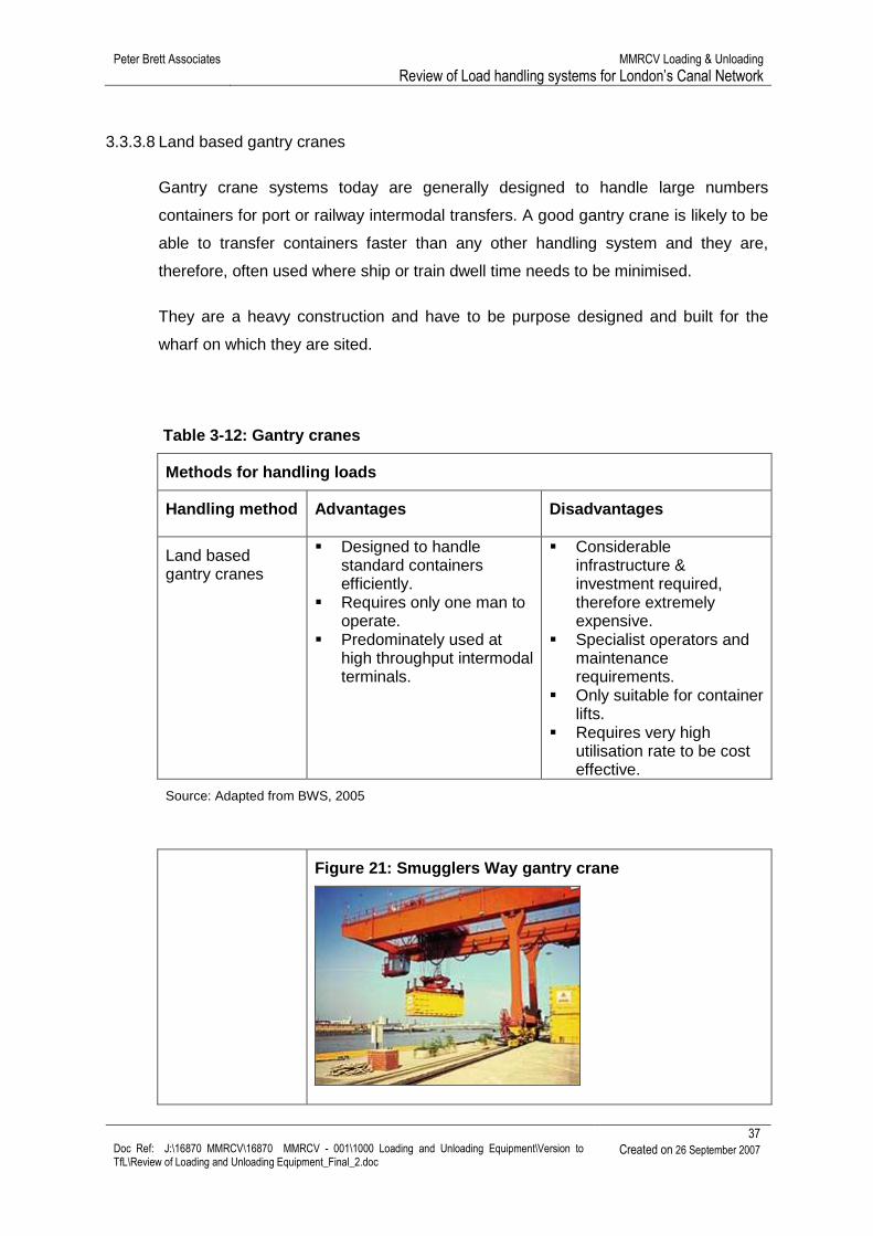
Figure 21: Smugglers Way gantry crane
Peter Brett Associates MMRCV Loading & Unloading Review of Load handling systems for London’s Canal Network
38 Doc Ref: J:\16870 MMRCV\16870 MMRCV - 001\1000 Loading and Unloading Equipment\Version to TfL\Review of Loading and Unloading Equipment_Final_2.doc
Created on 26 September 2007
This is a high cost option and is only suitable for a facilities that will be handling large volumes of containers for a long period. Purchase cost: £2,000,000 Maintenance cost at £12.50p/h: £22,812 Electricity cost at £0.95pKwh: £1,733 Trained operator: £26,000 Reinforcement of Pier: £2,000,000 Total yearly outlay including purchase approximately £4 million Yearly outlay thereafter £76,545
At present there is a proposal that this type of equipment might be appropriate at two
locations (Hackney and Edmonton EfW) on the Lee Navigation for the handling of
multimodal refuse vehicle (MMRCV) containers, although the scoping study does
recommend that full feasibility study is carried out, in order to compare this system
with other handling options.
3.3.3.9 Innovative use of existing equipment
It is not inconceivable that any suitably sized piece of handling equipment can be
used onboard a craft. For example:
� British Waterways have mounted excavators within barges for dredging and
rubbish clearance of the GUC and Lee navigation. In the case of the GUC,
the machine sits within the hold permitting it to reach over the side barge to
perform its work (see Figure 17 for the Lee Navigation adaptation to this
approach).
� Small mobile shovels (e.g. Bobcat) are able to operate on barges since they
are of a size which allows them to fit into the hold. They can be either lifted or
driven on (using a suitable ramp) and used to load other buckets fitted to land
cranes.
Similarly smaller forms of equipment found on construction sites are used for
transferring materials between craft and the wharf, for example:
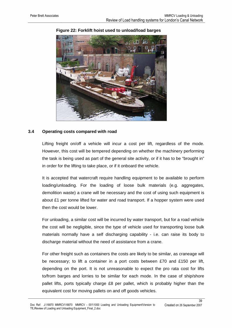
� Forklift trucks, which have an extending arm, are used for unloading barges
for canalside building works. As Figure 22 shows, these are able to operate in
small areas, but capable of lifting pre-packaged aggregates (e.g. jumbo bag
weighing about 1 tonne) and pallets of bricks and other materials.
Peter Brett Associates MMRCV Loading & Unloading Review of Load handling systems for London’s Canal Network
39 Doc Ref: J:\16870 MMRCV\16870 MMRCV - 001\1000 Loading and Unloading Equipment\Version to TfL\Review of Loading and Unloading Equipment_Final_2.doc
Created on 26 September 2007
Figure 22: Forklift hoist used to unload/load barge s
3.4 Operating costs compared with road
Lifting freight on/off a vehicle will incur a cost per lift, regardless of the mode.
However, this cost will be tempered depending on whether the machinery performing
the task is being used as part of the general site activity, or if it has to be “brought in”
in order for the lifting to take place, or if it onboard the vehicle.
It is accepted that watercraft require handling equipment to be available to perform
loading/unloading. For the loading of loose bulk materials (e.g. aggregates,
demolition waste) a crane will be necessary and the cost of using such equipment is
about £1 per tonne lifted for water and road transport. If a hopper system were used
then the cost would be lower.
For unloading, a similar cost will be incurred by water transport, but for a road vehicle
the cost will be negligible, since the type of vehicle used for transporting loose bulk
materials normally have a self discharging capability - i.e. can raise its body to
discharge material without the need of assistance from a crane.
For other freight such as containers the costs are likely to be similar, as craneage will
be necessary; to lift a container in a port costs between £70 and £150 per lift,
depending on the port. It is not unreasonable to expect the pro rata cost for lifts
to/from barges and lorries to be similar for each mode. In the case of ship/shore
pallet lifts, ports typically charge £8 per pallet, which is probably higher than the
equivalent cost for moving pallets on and off goods vehicles.
Peter Brett Associates MMRCV Loading & Unloading Review of Load handling systems for London’s Canal Network
40 Doc Ref: J:\16870 MMRCV\16870 MMRCV - 001\1000 Loading and Unloading Equipment\Version to TfL\Review of Loading and Unloading Equipment_Final_2.doc
Created on 26 September 2007
4 Canal locations and equipment options
4.1 Introduction
There are many points along London’s canals at which the loading and unloading of
craft can be achieved. However, the area of the land available will influence the
choice of handling equipment that can be sensibly used for the task it needs to
perform, regardless of the cargo handled. For example, a gantry crane, which is a
large machine compared with other forms of equipment, is only suitable for a wharf
that has sufficient space to accommodate a structure that is likely to be 20m wide,
excluding other vehicles manoeuvring areas.
As part of the study, a number of sites have been visited in order to consider the
handling equipment options that could be sited along side the canal. Since at this
time a relatively limited number of wharves are operating any type of craneage, few
examples exist. Those which are known comprise:
� Conveyor and hopper for loading gravel/sand at on the GUC at Denham
� Excavator fitted with clamshell bucket for unloading aggregates at Hanson
site, West Drayton (GUC)
� Wheeled mobile crane for lifting boats in/out of water at Uxbridge Boat Centre
(GUC)
� A straddle boat hoist at Adelaide Dock
4.2 Sites and their options
The West London Canal Network study provided a detailed catalogue of points at
which access could be gained to the GUC and the type of activity that could
potentially take place; however, it did not suggest types of craneage for these sites.
As mentioned, important factors such as the type of cargo, the volume to be handled
and the permanency of the freight flow will influence the choice of crane, since there
is a number of alternative types of equipment that can fulfil the same role.
Generally, no decision will be made about the type of craneage required until the site
operator is able to define the cargo to move by water. It will also be necessary to
carry out some form of feasibility assessment unless the operator is fully aware of
Peter Brett Associates MMRCV Loading & Unloading Review of Load handling systems for London’s Canal Network
41 Doc Ref: J:\16870 MMRCV\16870 MMRCV - 001\1000 Loading and Unloading Equipment\Version to TfL\Review of Loading and Unloading Equipment_Final_2.doc
Created on 26 September 2007
and comfortable with using particular types of machinery. For example, if Hanson
were to operate another canalside facility, it is possible it would automatically opt for
the same set up as used at the West Drayton site. However, if the volumes handled
were to be significantly different (e.g. much higher), it is possible they would opt for
equipment with a greater transfer capacity.
Along the Lee Navigation there are a number of canalside industrial redevelopments,
which as part of their renewal, have new wharf moorings included, although not
presently used. From brief observations of these sites it appears that they could
serve as transfer point with the canal and should be able to accommodate mobile
lifting equipment.
It is unrealistic in this review to comment upon which type of equipment can/should
be used at specific canalside sites, as there are too many unknowns. This type of
issue can only be resolved as and when a wharf plans to become operational.
Peter Brett Associates MMRCV Loading & Unloading Review of Load handling systems for London’s Canal Network
42 Doc Ref: J:\16870 MMRCV\16870 MMRCV - 001\1000 Loading and Unloading Equipment\Version to TfL\Review of Loading and Unloading Equipment_Final_2.doc
Created on 26 September 2007
5 Closing remarks
In summary, it can be said that there are four main groups of equipment for
loading/unloading a barge: reach stackers, vehicle mounted systems, common
mobile construction site and road cranes, and harbour and gantry cranes. They all
have strengths and weaknesses, but much depends on the state the wharf, the cargo
to be handled and accessibility to the site. A summary of the key characteristics of
handling systems is provided in Table 5-1 at the end of this chapter.
An important consideration for London canals is the extent to which equipment has to
reach out over the barge, which on the Lee Navigation is essentially 5.5m (18ft) and
4.2m (14ft) on the GUC. Since 4.2m wide barge will not accommodate a two twenty
foot containers side-by-side (because they are 2.4m (8’) wide) it will only be possible
to carry one line of up to 3 containers loaded centrally for balance, which means that
the edge of a container will be at least a metre away from the edge of the wharf. On
the Lee Navigation it is theoretically possible to load eight TEUs (4 in length by 2 in
width) into a dumb barge, but it would required to be specifically designed and built to
accommodate the containers.
Mobile road cranes can be used as a substitute for a reach stacker, although more
cumbersome to use. They are designed to lift from a single hook, which is not ideal
for lifting a container, as in practice a rigid spreader needed, which is able to grab a
container by its four corner twist lock points and lift it straight up. Mobile cranes can
be fitted with a spreader, but the attachment is to a single hook, so it tends to swing
about a lot. In practise this means that loading and unloading takes longer.
Furthermore, the wharf will require sufficient space in order to accommodate jacks
and supporting arms which stabilise the crane itself, so reducing its versatility.
However, it can be a cheap option if, for example, only relatively few containers have
to load/unload once or twice a week, since the mobile crane can be rented in for the
days it is needed.
Given that these cranes have a single hook they are an obvious choice where
individual loads need lifting (e.g. girders, skips), since straps and chains can be used.
Construction site cranes imply using either a tracked or wheeled excavator fitted with
a suitable bucket for lifting loose bulks (e.g. aggregates, soil, rubble). Cemex uses
Peter Brett Associates MMRCV Loading & Unloading Review of Load handling systems for London’s Canal Network
43 Doc Ref: J:\16870 MMRCV\16870 MMRCV - 001\1000 Loading and Unloading Equipment\Version to TfL\Review of Loading and Unloading Equipment_Final_2.doc
Created on 26 September 2007
this equipment for unloading barges at its wharves on the Thames and Severn, and
Hanson at West Drayton. They are relatively cheap to operate and can be use in
other location around the site.
Vehicle mounted container handling cranes would appear to have some important
advantages for low throughput sites and, particularly, for MMRCV operation. These
systems would be particularly attractive for trial operation, as Containerlift vehicles
can be hired for short term use and the equipment can be moved between sites. For
example, a crane could load a train of barges at one location and drive to the
destination to unload the same train of barges.
The most elaborate, costly and specialised are harbour and gantry cranes. These are
heavy duty machines and generally best suited to high volumes of work in a railway
yard or seaport. They have extensive metal frames, usually supported by wheeled
bogies running on rails, and it has a control cabin, a hoist and a spreader within the
frame. A large financial commitment is required for the wharf to support one of these,
in the form of providing strengthened foundations, rails and beams; something in the
order of £4million. Such craneage is only installed if high volumes are anticipated.
The remaining special case is skips. These can be transferred by the skip lorry
to/from the barge, providing the embankment or wharf is strong enough to cope with
the weight and pressure place on the rear of the vehicle as the lift takes place. The
skips are standard to the waste industry, but if used in a “Pond skater” type system
the bodywork would have to be watertight.
In conclusion, for many situations a vehicle mounted container system may be
suitable, but for large throughput locations it is expected that a reach stacker would
be the best option when lifting containers. A mobile crane is a good solution for
general purpose lifting and an excavator is the preferred solution for loose bulks.
Peter Brett Associates MMRCV Loading & Unloading
Review of Load handling systems for London Canal Network
44 Doc Ref: J:\16870 MMRCV\16870 MMRCV - 001\1000 Loading and Unloading Equipment\Version to TfL\Review of Loading and Unloading Equipment_Final_2.doc Created on 26 September 2007
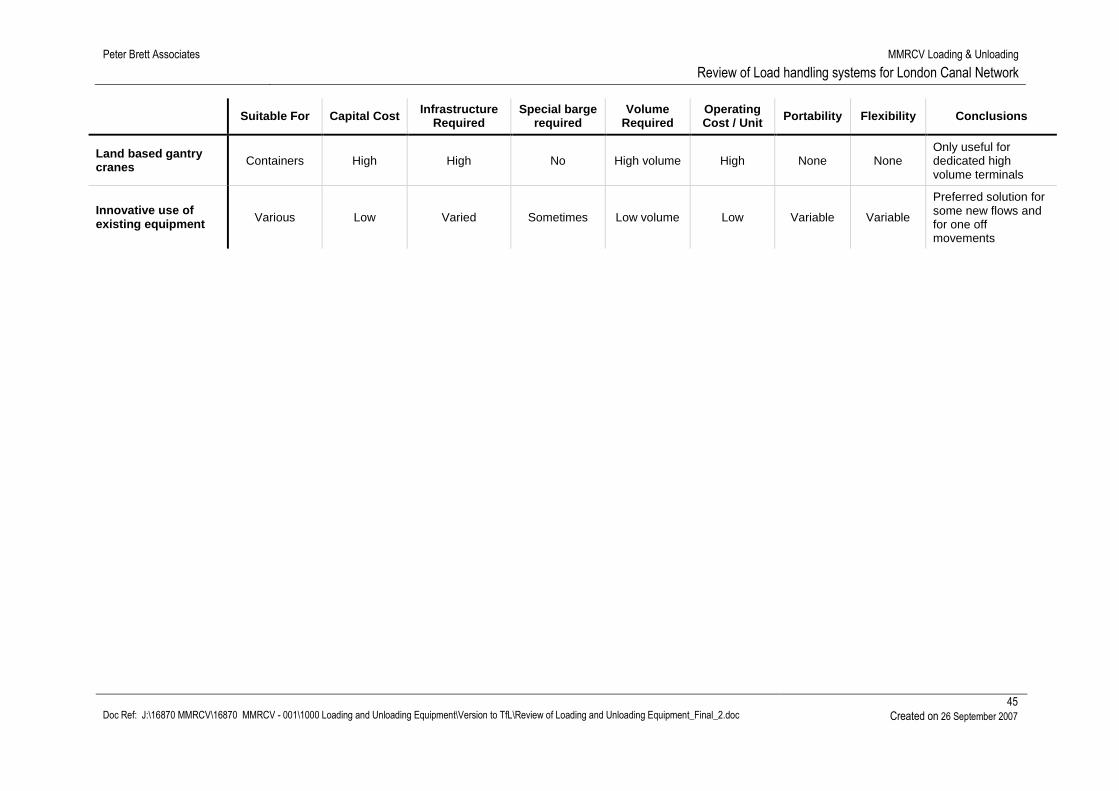
Table 5-1: Summary of key characteristics of handli ng systems
Suitable For Capital Cost Infrastructure Required
Special barge required
Volume Required
Operating Cost / Unit Portability Flexibility Conclusions
Conveyor Loose bulk Medium May be high No High volume Very low Low None Recommended for high volume bulk loading
Excavator / Grab Loose bulk Low Some reinforcement No Low volume Medium High High
Recommended for lower volumes and for bulk unloading
Standard Skip Loose materials Low Minimal Not
necessarily Low volume Very low High High
Can be used for demolition waste and aggregates. Potential vastly improved if special barge system is developed
Hook and Haul Loose materials
Low Minimal Yes Low volume Very low High High As for skip but technology unproven
Land cranes - wheeled / crawler All materials Medium Some
reinforcement No Medium
volume Medium High High
Useful for irregular flows or where it can be used for other functions
Land cranes - fixed / tracked All materials High High No High volume Medium None Low
Only useful for dedicated high volume terminals
Vessel mounted cranes
Loose bulk and pallets
etc. Low None Yes Low volume Very low High Low
Useful for irregular flows to unprepared wharves
Container reach-stackers Containers High High No High volume High High High
Useful for locations where significant volumes of containers are handled
Goods Vehicle Based Container Handling Systems
Containers Low Some reinforcement No Low volume Medium /
Low High High Useful for low volumes or irregular flows
Peter Brett Associates MMRCV Loading & Unloading
Review of Load handling systems for London Canal Network
45 Doc Ref: J:\16870 MMRCV\16870 MMRCV - 001\1000 Loading and Unloading Equipment\Version to TfL\Review of Loading and Unloading Equipment_Final_2.doc Created on 26 September 2007
Suitable For Capital Cost Infrastructure Required
Special barge required
Volume Required
Operating Cost / Unit Portability Flexibility Conclusions
Land based gantry cranes Containers High High No High volume High None None
Only useful for dedicated high volume terminals
Innovative use of existing equipment Various Low Varied Sometimes Low volume Low Variable Variable
Preferred solution for some new flows and for one off movements