Review on VSI Switch Fault Tolerant Control Systems for Electric Vehicle Drivetrains A. Tashakori Abstract—Electric Vehicles (EVs) are an effective solution for reducing greenhouse gas emissions to the atmosphere. Safety is the most crucial issue in the automotive industry and any fault in the EV drivetrain may results in a fatal accident. This paper discusses the dynamic performance of EVs under drivetrain Voltage Source Inverter (VSI) switch faults and presents the suitable Fault Diagnosis Algorithm (FDA) and remedial strategy for EV applications. Physical testing of drivetrain faults in EVs is both expensive and extremely difficult; therefore the Nissan Leaf and the Lightning GT EVs are simulated using a validated model of the Permanent-Magnet Synchronous Motor (PMSM) and their performances investigated under faulty drivetrain conditions. Simulation results show the necessity of implementing Fault Tol- erant Control Systems (FTCSs) in EV drivetrain electric motor drives. Various fault diagnosis algorithms of the VSI switch faults in PMSM drives are reviewed and their merits and demerits are discussed. Existing fault tolerant control inverter topologies are also reviewed and compared based on EV application requirements. Finally, suitable FDA and fault tolerant control inverter topology for EV drivetrain application are recommended to maintain safe and optimal vehicle performance in the post- fault condition. Index Terms—Electric Vehicles, VSI switch faults, PMSM motors, Fault diagnosis algorithms, Fault tolerant control inverter topologies. I. I NTRODUCTION E LECTRIC vehicle adoption is limited, in general, due to both high cost and poor mileage. While Hybrid Electric Vehicles (HEVs) are more popular due to the improved mileage; their cost is still much higher than comparable Internal Combustion Engine (ICE) vehicles. Limitations of natural resources, extensive carbon emissions resulting from burning fossil fuels and new standards and policies regarding efficiency and carbon emissions of motor vehicles defined by various governments in transportation sector have lead auto- motive industries to develop highly efficient, zero-emission and low-cost, pure-electric vehicles for the future. Automobile manufacturers are also working on Fuel Cell Vehicles (FCVs), which produce the electrical energy from the chemical reac- tion of hydrogen and oxygen. However cost, durability and temperature limitations coupled with a lack of both refueling infrastructure, and suitable solutions to hydrogen storage and on-board delivery, are the main challenges of FCVs [1]. Various electric motors are used for propulsion of EV’s so far. Comparison studies show permanent-magnet synchronous motors (brushless DC motors in particular) are the most suitable choice for low- and medium-duty passenger vehicles Manuscript is received on January 12, 2016; revised on April 26, 2016. A. Tashakori is a postdoctoral research engineer at the Faculty of Sci- ence, Engineering and Technology, Swinburne University of Technology, Melbourne, VIC 3101 Australia, e-mail: [email protected]. [2]. In-wheel motor technology have been used by some manufacturers in recent years, however central drive EVs are also popular. Drivetrain electric motors used in commercial passenger EVs around the world are given in Table I with electric vehicles are sorted by the released year. Induction and permanent-magnet synchronous motors are widely used in commercial passenger EV’s by various manufacturers; how- ever PMSMs are the most popular in the recent years. PMSM are mainly divided into two categories based on their back- EMF voltage waveform pattern. PMSMs with sinusoidal back- EMF voltage are known as Permanent-Magnet AC (PMAC) motors and those with trapezoidal back-EMF voltage pattern are called Brushless DC (BLDC) motors. High efficiency, high output power to size ratio, constant torque over a wide speed range, fast dynamic response (due to the permanent- magnet rotor), lower maintenance needs (due to the absence of brushes), noiseless operation and high operating speed ranges are the main advantages of PMSMs over other motor types for passenger EV applications [2]. Improving the safety, efficiency and energy storage tech- nologies of electric vehicles are the most significant research interests nowadays. Research on the EV energy storage tech- nologies are concentrated on increasing energy capacities, and thus EV mileage, as well as reducing battery costs, and hence market price. Employing FTCSs effectively improves the reliability of electric motor drives used in EVs drivetrain and consequently the vehicle safety [3]. A FTCS must detect, identify and isolate faults and apply remedial strategies to maintain normal performance of the system in the post-fault condition. Various electrical and mechanical faults may occur in PMSMs. Stator windings, inverter switches and inverter DC- link are subjected to open/short-circuit faults. Permanent- magnet rotors are subjected to mechanical faults such as eccentricity, asymmetry, inbalanced, damage to the magnet, rotor misalignment and bearing faults [4]. Additionally, the position sensors may suffer their own issues, including failure due to flaws in the magnet core such as corrosion, cracks, residual magnetic fields and core breakage; changing core- magnet fields due to temperature fluctuations; variations in bias current and orientation of induced magnetic fields due to mechanical shocks and vibration [5]; and misalignment of the sensors during installation that adds low-frequency harmonics in the motor torque ripple [6]. Some faults degrade the PMSM performance and trigger further major faults immediately, while others may only cause motor breakdown if they persist for longer periods [7]. Therefore a number of FTCSs should run simultaneously for various faults, with their performance priorities predefined according to the likely effects on motor Engineering Letters, 24:2, EL_24_2_14 (Advance online publication: 18 May 2016) ______________________________________________________________________________________
Transcript
Review on VSI Switch Fault Tolerant ControlSystems for Electric Vehicle Drivetrains
A. Tashakori
Abstract—Electric Vehicles (EVs) are an effective solution forreducing greenhouse gas emissions to the atmosphere. Safety isthe most crucial issue in the automotive industry and any faultin the EV drivetrain may results in a fatal accident. This paperdiscusses the dynamic performance of EVs under drivetrainVoltage Source Inverter (VSI) switch faults and presents thesuitable Fault Diagnosis Algorithm (FDA) and remedial strategyfor EV applications. Physical testing of drivetrain faults in EVs isboth expensive and extremely difficult; therefore the Nissan Leafand the Lightning GT EVs are simulated using a validated modelof the Permanent-Magnet Synchronous Motor (PMSM) and theirperformances investigated under faulty drivetrain conditions.Simulation results show the necessity of implementing Fault Tol-erant Control Systems (FTCSs) in EV drivetrain electric motordrives. Various fault diagnosis algorithms of the VSI switch faultsin PMSM drives are reviewed and their merits and demeritsare discussed. Existing fault tolerant control inverter topologiesare also reviewed and compared based on EV applicationrequirements. Finally, suitable FDA and fault tolerant controlinverter topology for EV drivetrain application are recommendedto maintain safe and optimal vehicle performance in the post-fault condition.
Index Terms—Electric Vehicles, VSI switch faults, PMSMmotors, Fault diagnosis algorithms, Fault tolerant control invertertopologies.
I. INTRODUCTION
ELECTRIC vehicle adoption is limited, in general, due toboth high cost and poor mileage. While Hybrid Electric
Vehicles (HEVs) are more popular due to the improvedmileage; their cost is still much higher than comparableInternal Combustion Engine (ICE) vehicles. Limitations ofnatural resources, extensive carbon emissions resulting fromburning fossil fuels and new standards and policies regardingefficiency and carbon emissions of motor vehicles defined byvarious governments in transportation sector have lead auto-motive industries to develop highly efficient, zero-emissionand low-cost, pure-electric vehicles for the future. Automobilemanufacturers are also working on Fuel Cell Vehicles (FCVs),which produce the electrical energy from the chemical reac-tion of hydrogen and oxygen. However cost, durability andtemperature limitations coupled with a lack of both refuelinginfrastructure, and suitable solutions to hydrogen storage andon-board delivery, are the main challenges of FCVs [1].
Various electric motors are used for propulsion of EV’s sofar. Comparison studies show permanent-magnet synchronousmotors (brushless DC motors in particular) are the mostsuitable choice for low- and medium-duty passenger vehicles
Manuscript is received on January 12, 2016; revised on April 26, 2016.A. Tashakori is a postdoctoral research engineer at the Faculty of Sci-
ence, Engineering and Technology, Swinburne University of Technology,Melbourne, VIC 3101 Australia, e-mail: [email protected].
[2]. In-wheel motor technology have been used by somemanufacturers in recent years, however central drive EVs arealso popular. Drivetrain electric motors used in commercialpassenger EVs around the world are given in Table I withelectric vehicles are sorted by the released year. Inductionand permanent-magnet synchronous motors are widely usedin commercial passenger EV’s by various manufacturers; how-ever PMSMs are the most popular in the recent years. PMSMare mainly divided into two categories based on their back-EMF voltage waveform pattern. PMSMs with sinusoidal back-EMF voltage are known as Permanent-Magnet AC (PMAC)motors and those with trapezoidal back-EMF voltage patternare called Brushless DC (BLDC) motors. High efficiency,high output power to size ratio, constant torque over a widespeed range, fast dynamic response (due to the permanent-magnet rotor), lower maintenance needs (due to the absence ofbrushes), noiseless operation and high operating speed rangesare the main advantages of PMSMs over other motor typesfor passenger EV applications [2].
Improving the safety, efficiency and energy storage tech-nologies of electric vehicles are the most significant researchinterests nowadays. Research on the EV energy storage tech-nologies are concentrated on increasing energy capacities,and thus EV mileage, as well as reducing battery costs, andhence market price. Employing FTCSs effectively improvesthe reliability of electric motor drives used in EVs drivetrainand consequently the vehicle safety [3]. A FTCS must detect,identify and isolate faults and apply remedial strategies tomaintain normal performance of the system in the post-faultcondition.
Various electrical and mechanical faults may occur inPMSMs. Stator windings, inverter switches and inverter DC-link are subjected to open/short-circuit faults. Permanent-magnet rotors are subjected to mechanical faults such aseccentricity, asymmetry, inbalanced, damage to the magnet,rotor misalignment and bearing faults [4]. Additionally, theposition sensors may suffer their own issues, including failuredue to flaws in the magnet core such as corrosion, cracks,residual magnetic fields and core breakage; changing core-magnet fields due to temperature fluctuations; variations inbias current and orientation of induced magnetic fields due tomechanical shocks and vibration [5]; and misalignment of thesensors during installation that adds low-frequency harmonicsin the motor torque ripple [6]. Some faults degrade the PMSMperformance and trigger further major faults immediately,while others may only cause motor breakdown if they persistfor longer periods [7]. Therefore a number of FTCSs shouldrun simultaneously for various faults, with their performancepriorities predefined according to the likely effects on motor
TABLE IDRIVETRAIN ELECTRIC MOTORS USED IN COMMERCIAL EVS
EV name Manufacturer Electric Country/company motor Release year
C-ZEN Courb Induction France/2014Soul EV Kia PMSM South Korea/2014Lightning Lightning 2 in-wheel UK/2014GT Car synchronousBMW MiniE BMW Induction Germany/2013SLS AMG Mercedes-Benz 4 in-wheel Germany/2013Eletric synchronousSpark General Motors PMSM USA/2013Tesla Tesla Motors Induction USA/2012Model SFiat 500e Fiat PMSM Italy/2012Twizy Renault Induction France/2012QBEAK ECOmove 2 in-wheel Denmark/2012
PMACFocus Electric Ford PMSM USA/2011VW e-Golf Volkswagen PMAC Germany/2011Nissan Leaf Nissan BLDC Japan/2010Fit EV Honda PMAC Japan/2010Buddy Buddy Electric DC Norway/2010BYD E6 BYD Auto BLDC China/2010Electron Ross Blade Induction Australia/2010Morgan Morgan motors BLDC UKPlus E 2010VW e-up! Volkswagen PMSM Germany/2009Zoe Renault PMSM France/2009Fluence ZE Renault PMSM France/2009C1 ev’ie Citroen Induction France/2009Mitsubishi Mitsubishi BLDC Japan/2009i-MiEVSmart Smart Automobile BLDC Germany/2009Think City Think Global Induction Norway/2008ZeCar Stevens Vehicles Induction UK/2008Venturi Venturi 4 in-wheel France/2006Fetish PMSMMyCar EuAuto BLDC Hong Kong/2003
TechnologyREVAi REVA Electric Induction India/2001
performance if two or more faults happen over a short timeintervals [3].
Simulation models are used to reduce the expense andlength of the design process of advanced systems; as such, themodelling of HEVs has grown since the 1970s [8]. Simulationmodels are used to study various aspects of vehicle operationsuch as vibration, handling, noise, dynamic performance,safety, stability, reliability and energy consumption [9]. How-ever there are few simulation models of pure electric vehicleswith access to VSI switches, which are vital for studying thevehicle performance under inverter faults in drivetrain electricmotors. Therefore the Nissan Leaf from Japan with a centraldrivetrain and the Lightning GT from UK with a rear by-wheeldrivetrain simulation model are modeled in this paper and theirperformance have been studied under both normal (no-fault)and inverter switch faults conditions. Vehicle dynamics suchas vehicle speed, wheel rotation and drivetrain electric-motorcharacteristics were also compared and analyzed subsequently.Finally, FDAs and fault tolerant inverter topologies of PMSMsare presented and their merits and limitations are discussedbased on EV drivetrain application requirements.
II. ELECTRIC VEHICLE MODELING
Steady-state, dynamic and quasi-static are the main vehi-cle modeling techniques. Steady-state models, as the nameimplies, are concentrated on the steady-state response of themodel, neglecting transient conditions. Transient conditionsare considered in dynamic models; therefore these modelsare more complex to develop and need more computationscompared to steady state models. Finally, quasi-static modelsare a combination of the steady state and transient models,which is more suitable for EV drive train modeling [1].
An EV model consists of a number of sub-systems andcomponents; such as electric motors, motor drivers, motorcontrollers, gearboxes, tires, coupling mechanical shafts, ve-hicle body and so on which should interconnected to eachother. A complex system including a number of sub-systemcan be developed as a structural or functional model. Astructural model is based on interconnecting sub-systems andcomponents according to their physical structure, whereas afunctional model is based on interconnecting mathematicalfunctions of sub-systems [1]. Vehicle simulation packages suchas ADvanced Vehicle SimulatOR (ADVISOR), PowertrainSystem Analysis Toolkit (PSAT), Autonomie, AVL AdvancedSimulation Technologies (AVL AST) and Virtual Test Bed(VTB) are examples of the structural model.
ADVISOR is developed by US National Renewable EnergyLaboratory (NREL). ICE vehicle, EV, HEV and FCV canbe modeled and their performance, fuel consumption andemissions can be analyzed by ADVISOR [9]. PSAT is devel-oped by Argonne National Laboratory, sponsored by the U.S.Department of Energy (DoE) and has been licensed to morethan 130 companies, universities, and research laboratoriesworldwide [10]. It is a quasi-steady model developed inMATLAB/Simulink using C language with hardware in theloop testing capability [9], allowing the modeling of light,medium and heavy duty conventional, hybrid and pure electricvehicles. ADVISOR and PSAT are modeled based on look-up tables and efficiency maps of the drivetrain componentsand are suitable for dynamic modeling of the overall systemunder extreme operating conditions [9]. Autonomie is a newsimulation software, developed by Argonne National Labora-tory in collaboration with General Motors, that has replacedPSAT since 2006. It supports the rapid integration and anal-ysis of powertrain/propulsion systems and technologies underdynamic/transient testing conditions [11]. AVL AST providesa set of comprehensive simulation tools with embedded fullyvalidated physical models that enables vehicle performanceanalysis and optimization of vehicle and powertrain configura-tions [12]. Providing validated physical model of componentsmakes AVL AST a reliable vehicle simulation tool that canbe used for the product development process, or in researchstudies for further improvements. VTB provides a combina-tion of topological and mathematical models suitable for theprototyping of large-scale, multi-disciplined dynamic systemswith advanced visualizations of simulation results capability[13][14]; It is a powerful tool for EV modeling, however ithas limited ability to model communication networks withinthe vehicle [15].
Studying the vehicle performance under drivetrain fault con-dition requires an accurate EV model including accessibilityto parameters of each components within the three phase VSI,the propulsion electric motors and their control drives. Forinstance, in the case of studying VSI switch faults effectson EV performance, most of the discussed vehicle simulationpackages do not provide user access to the drivetrain electricmotors and inverter drive switches. Therefore, in this paper aPMSM motor, its inverter drive and motor controller are sim-ulated and validated through experimental data. The validatedPMSM drive is integrated with gearbox, tire, mechanical shaftsand vehicle body models from the Simscape library to build anoverall EV model in Simulink. The developed model providesaccessibility to the inverter switches to implement open/close-circuit switch faults and study the EV performance under suchfaults.
A. PMSM Drive Modeling and Validation
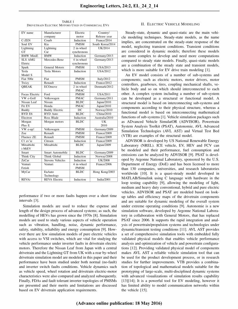
The principle of PMSMs operation is similar to conventionalDC motors that commutation is done electronically ratherthan by brushes [16]. PMSMs are more efficient, have fasterdynamic responses and higher speed ranges compared toconventional DC motors; however, their control drives aremore complex due to the electronic commutation [7]. Elec-tronic commutation is based on the permanent-magnet rotorposition. PMSM drives are mainly divided into drives usingsensors to detect the rotor position and sensorless drives. Thispaper concentrates on a three phase PMSM using Hall Effectsensors for rotor position detection. The schematic diagram ofa PMSM drive is shown in Fig. 1.
Fig. 1. The schematic diagram of a PMSM drive
An accurate and validated PMSM model is required to studymotor performance under inverter drive faults. Therefore inthis paper, a PMSM drive is modeled and validated throughexperimental data. The model consists of a permanent-magnet
synchronous motor, a three phase VSI and a closed-loopcontrol algorithm. Hall Effect sensor signals are decoded todetect the permanent-magnet rotor position, and the appropri-ate voltage space vectors are chosen to commutate the motorbased on rotor position. The permanent-magnet rotor position,corresponding Hall Effect signals and inverter switches statusof the PMSM are shown in Table II. Switching signals arefed to the three phase VSI to supply voltages to the motorwindings. A digital Pulse Width Modulation (PWM) techniqueis implemented to control the speed. The PWM switchingsignal is applied to the upper side switches (S1, S3, S5) ofinverter.
TABLE IIPMSM DRIVE SWITCHING ALGORITHM
Electrical Ha Hb Hc Inverter switches statusdegree S1 S2 S3 S4 S5 S6
30-90 0 1 0 On Off Off On Off Off
90-150 1 1 0 On Off Off Off Off On
150-210 1 0 0 Off Off On Off Off On
210-270 1 0 1 Off On On Off Off Off
270-330 0 0 1 Off On Off Off On Off
330-30 0 1 1 Off Off Off On On Off
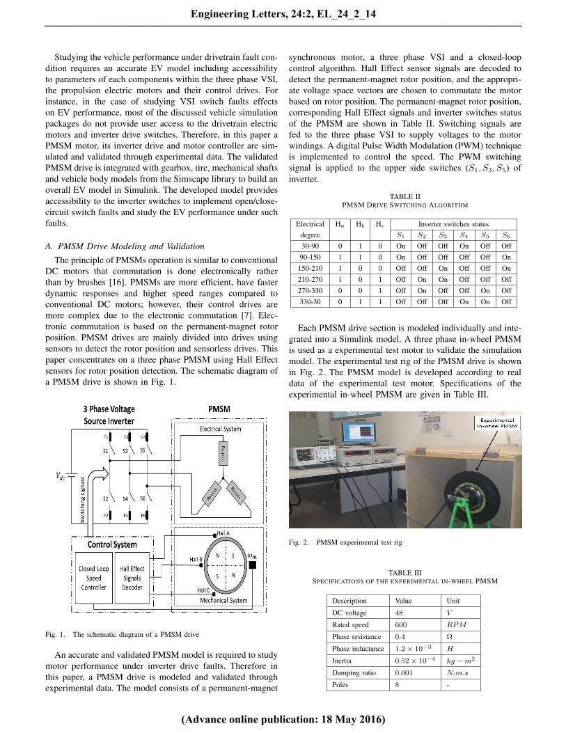
Each PMSM drive section is modeled individually and inte-grated into a Simulink model. A three phase in-wheel PMSMis used as a experimental test motor to validate the simulationmodel. The experimental test rig of the PMSM drive is shownin Fig. 2. The PMSM model is developed according to realdata of the experimental test motor. Specifications of theexperimental in-wheel PMSM are given in Table III.
Fig. 2. PMSM experimental test rig
TABLE IIISPECIFICATIONS OF THE EXPERIMENTAL IN-WHEEL PMSM
The experimental in-wheel PMSM and the simulation modelwere tested under the same operating conditions. The inbuiltdrum brake of the in-wheel motor hub is used to apply 1.54N.m torque load (measured based on manufacturer test data-sheet) to the test motor at 600 RPM . Speed and torquecharacteristics of the modeled PMSM are shown in Fig. 3.As can be seen the motor is running at 600 RPM and theproduced electric torque is pulsating around the torque loadwith the torque ripple amplitude of 0.6 N.m. The simulationtorque response matches closely to the manufacturer test data-sheet at 600 RPM .
Fig. 3. Speed and torque characteristics of the modeled PMSM
Line voltages and Hall Effect signals of phase A of thetest motor and the simulated PMSM model are shown inFig. 4. The pattern of line voltages and commutation intervalsmatch closely. Good agreements between the simulation andexperiment results validate the developed model of the in-wheel PMSM. This validated PMSM model was subsequentlyused in the Nissan Leaf and the Lightning GT models.
B. Nissan Leaf and Lightning GT Modeling
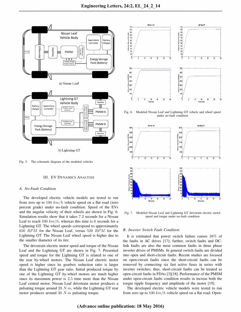
The Nissan Leaf and Lightning GT electric vehicles aremodeled by using real data in the developed model. Theschematic diagram of the modeled electric vehicles are shownin Fig. 5. The Nissan Leaf has a central PMSM driven frontwheels through a fixed ratio gearbox and a differential, whilethe Lightning GT has two by-wheel PMSMs propelling eachrear wheel through a fixed ratio gearbox.
The Nissan Leaf has a 80 kW PMSM central motor thatproduces the maximum torque of 280 N.m connected to agearbox with a final reduction ratio of 7.9377 driving thefront wheels. The maximum torque available at wheels isaround 2222 N.m by neglecting gearbox and differentiallosses. This compares with the Lightning GT, which has two
Fig. 4. Line voltage and Hall Effect signal of the PMSM
by-wheel 200 kW PMSMs that each of them produces themaximum torque of 364 N.m, connected to a gearbox withfinal reduction ratio of 5.5 driving the rear wheels with amaximum available torque of around 4000 N.m, neglectinggearbox losses. The Nissan Leaf drivetrain configuration isless efficient than the Lightning GT due to the existence ofa differential. Drivetrain and vehicle body specification of themodeled EVs are summarized in Table IV.
TABLE IVSPECIFICATIONS OF THE MODELED ELECTRIC VEHICLES
Description Nissan Leaf Lightning GTDrivetrain Type A Central Motor Two By-Wheel Motorspropelled wheels Front Wheels Rear wheelsElectric Motor Type PMSM PMSMMax Power (kW ) 80 2 × 200Max Torque (N.m) 280 2 × 364Gearbox Ratio 7.9377 5.5Kerb Mass (kg) 1567 1850Vehicle Dimension (m) 4.445/1.77/1.55 4.445/1.94/1.2
Fig. 5. The schematic diagram of the modeled vehicles
III. EV DYNAMICS ANALYSIS
A. No-Fault Condition
The developed electric vehicle models are tested to runfrom zero up to 100 km/h vehicle speed on a flat road (zeropercent grade) under no-fault condition. Speed of the EVsand the angular velocity of their wheels are shown in Fig. 6.Simulation results show that it takes 7.2 seconds for a NissanLeaf to reach 100 km/h, whereas this time is 6 seconds for aLightning GT. The wheel speeds correspond to approximately650 RPM for the Nissan Leaf, versus 520 RPM for theLightning GT. The Nissan Leaf wheel speed is higher due tothe smaller diameter of its tire.
The drivetrain electric motor speed and torque of the NissanLeaf and the Lightning GT are shown in Fig. 7. Presentedspeed and torque for the Lightning GT is related to one ofthe rear by-wheel motors. The Nissan Leaf electric motorspeed is higher since its gearbox reduction ratio is largerthan the Lightning GT gear ratio. Initial produced torque byone of the Lightning GT by-wheel motors are much highersince its maximum power is 2.5 time more than the NissanLeaf central motor. Nissan Leaf drivetrain motor produces apulsating torque around 20 N.m, while the Lightning GT rearmotor produces around 30 N.m pulsating torque.
Fig. 6. Modeled Nissan Leaf and Lightning GT vehicle and wheel speedunder no-fault condition
Fig. 7. Modeled Nissan Leaf and Lightning GT drivetrain electric motorspeed and torque under no-fault condition
B. Inverter Switch Fault Condition
It is estimated that power switch failure causes 38% ofthe faults in AC drives [17]; further, switch faults and DC-link faults are also the most common faults in three phaseinverter drives of PMSMs. In general switch faults are dividedinto open and short-circuit faults. Recent studies are focusedon open-circuit faults since the short-circuit faults can beremoved by connecting six fast active fuses in series withinverter switches; thus, short-circuit faults can be treated asopen-circuit faults in FDAs [3][18]. Performance of the PMSMunder open-circuit faults condition results in increas both thetorque ripple frequency and amplitude of the motor [19].
The developed electric vehicle models were tested to runfrom zero up to 100 km/h vehicle speed on a flat road. Open-
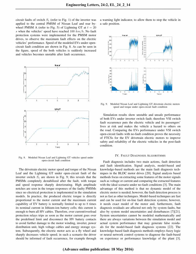
circuit faults of switch S1 (refer to Fig. 1) of the inverter wasapplied to the central PMSM of Nissan Leaf and rear by-wheel PMSM A (refer to Fig. 5) of Lightning GT at t = 20s when the vehicles’ speed have reached 100 km/h. No faultprotection systems were implemented for the PMSM motordrives, to observe the maximum fault effects on the electricvehicles’ performance. Speed of the modeled EVs under open-circuit fault condition are shown in Fig. 8. As can be seen inthe figure, speed of the both vehicles is suddenly increasedand vehicles becomes unstable after fault occurrence.
The drivetrain electric motor speed and torque of the NissanLeaf and the Lightning GT under open-circuit fault of theinverter switch S1 are shown in Fig. 9; this reveals that thePMSMs completely destabilized after the fault, with torqueand speed response sharply deteriorating. High amplitudenotches are seen in the torque responses of the faulty PMSMssince no electrical protection is implemented in the simulationmodels. In practice, the produced electric torque is directlyproportional to the motor current and the maximum currentcapability of EV battery is normally limited to up to 8 timesits nominal current in lithium-ion battery cells; this current isenough to burn all HV cables. Therefore, over current/overloadprotection relays trips as soon as the motor current goes overthe predefined limit and disconnect the HV battery contactsto avoid further damage to the motor winding, inverter, powerdistribution unit, high voltage cables and energy storage sys-tem. Subsequently, the electric motor acts as a fly wheel andsharply decreases vehicle speed; in such a scenario the drivershould be informed of fault occurrence, for example through
a warning light indicator, to allow them to stop the vehicle ina safe position.
Fig. 9. Modeled Nissan Leaf and Lightning GT drivetrain electric motorsspeed and torque under open-circuit fault condition
Simulation results show unstable and unsafe performanceof both EVs under inverter switch fault; therefore VSI switchfault occurrence puts the electric vehicle and its passengers’lives at risk and makes the vehicle a hazard to others onthe road. Comparing the EVs performance under VSI switchopen-circuit faults with no-fault condition proves the necessityof FTCSs for the EV drivetrain electric motors to improvesafety and reliability of the electric vehicles in the post-faultcondition.
IV. FAULT DIAGNOSIS ALGORITHMS
Fault diagnosis includes two main actions, fault detectionand fault identification. Signal analysis, model-based andknowledge-based methods are the main fault diagnosis tech-niques in the BLDC motor drives [20]. Signal analysis basedmethods focus on extracting some features of the motor signalssuch as voltage or current and comparing the extracted featureswith the ideal scenario under no-fault conditions [3]. The mainadvantage of this method is that no dynamic model of theelectric motor is needed; however, the fault detection process isnot as fast as other techniques. Model-based techniques are fastand can be used for on-line fault detection systems; however,it needs exact model of the motor and, furthermore, faultdiagnosis residuals are affected not only by system faults, butalso by system model uncertainties and disturbances [7][21].System uncertainties cannot be modeled mathematically andthere are always variations between the simulation model andactual system performance that may generate false residu-als for the model-based fault diagnosis systems [22]. Theknowledge-based fault diagnosis methods employs fuzzy logicor neural network control systems to diagnose the fault-basedon experience or performance knowledge of the plant [3].
Recently, a number of fault diagnosis techniques are usuallyembedded in advanced FDAs concurrently.
Existing fault diagnosis systems are mainly categorizedinto current-residual-based FDAs and voltage-residual-basedFDAs. Voltage-residual-based FDAs are inherently faster andhave higher immunity to disturbance and false fault diagnosis,yet require extra voltage sensors [23][24]. Current-residual-based FDAs are popular due to existence of the currentsensors inside inverters; however, they are not fast, resistantto disturbance nor capable of allocating the fault occurrenceinside either the motor or inverter [25]. They are also highlysensitive to transients scenarios that frequently occur in electricvehicles [24]. Since reliability of the fault detection is highlysignificant in EV drivetrain applications, this paper focuses onvoltage-residual-based FDAs for the PMSMs.
Four inverter fault diagnosis techniques based on variousvoltage sensing points of the PMSM are proposed that haveimproved the fault detection time significantly [25]. Voltageerrors are fault detection signatures in all reported techniques.Neutral point voltage of motors are needed in two of pro-posed techniques. These techniques are not reliable for faultdiagnosis in a closed-loop control scheme since neutral pointvoltage of the PMSM is not stable and floating during thehigh frequency PWM switching [3]. The pattern of the linevoltages of the PMSM is dependent on both operating speedand load torque of the motor; therefore the ideal referenceline voltages should change dynamically for reliable faultdiagnosis in applications that require continuous change ofspeed and load, such as electric vehicles [3]. Switch faultdetection method is proposed for voltage fed PWM invertersbased on the voltages across the lower switches of eachinverter leg [26]. The high noise susceptibility of the voltagesensors used inside the inverter, due to high frequency PWMswitching, is the main drawback of the reported techniquethat can decrease the reliability of the fault detection [3]. Aninverter switch fault detection using Field Programmable GateArray (FPGA) is reported by Karimi et al. that improves thefault detection time to less than 10 µs [27]. Although, theproposed fault detection algorithm is so complex, however,it is so fast due to the inherent high speed capability of theFPGAs. A neural network based fault diagnosis algorithm isproposed by Masrur et al. for the most common inverter faultsof induction motor drives in EV applications [28]. Featuresused to train the neural network to detect various faults areextracted from torque, voltage and current signals of the motor.The proposed method is complex, needs a large number ofsensors and the neutral point voltage measurement, but hasthe advantage of being extremely rapid [3]. A sectoral open-circuit switch fault diagnosis method for the inverter drive ofPMSMs are proposed by Choi and Lee [29]. This techniqueis based on comparison of pole voltages with the generatedsector-averaging residual. The main limitations of the proposedtechnique are its complexity and the offset compensationneeds of the generated averaging residual value within sectorsdue to the integration process. A low-cost open-circuit faultdiagnosis technique is proposed for the PWM VSI drive ofPMSMs that is based on Model Reference Adaptive System(MRAS) techniques and requires no extra voltage sensors [30].
The proposed method needs an exact model of the PMSM;increasing the complexity of the proposed algorithm; howeverthe fault detection time is improved to less than 0.91 ms.
A simple fault diagnosis algorithm for inverter open-circuitswitch faults in permanent-magnet synchronous motor driveshas been reported by this author in an earlier paper [3]. Aknowledge-based expert system is introduced to both detectthe open-circuit fault occurrence and identify the VSI faultyswitch based on the motor line voltages signal analysis.Switching algorithm of the PMSMs based on permanent-magnet rotor are shown in Table II. Inverter switch faults affectdirectly on the applied voltages to the motor. The ideal PMSMline voltages under no-fault and open-circuit faults of inverterswitches S1 and S2 (refer to the Fig. 1) conditions are shownin Fig. 10 [3].
Fig. 10. The PMSM line voltages under no-fault and inverter open-circuitfault conditions
This proposed fault diagnosis is based on Discrete FourierTransform (DFT) analysis of the PMSM line voltages. Linevoltages are measured for the specific intervals of time withrespect to the negative terminal of VSI DC-link to elimi-nate unwanted common mode noises and filtering needs [3].Spectral Energy Density (SED) of the PMSM line voltagescalculated from equation (2) are signature of both the faultdetection and identification. Calculated SED values of the suc-cessive time intervals are compared as shown in equation (3).A knowledge-based system is developed based on line voltagesSED errors by studying the PMSM performance under variousVSI switch fault conditions through a validated PMSM model.The proposed FDA is validated through experimental results.
In the proposed technique, prior knowledge of the linevoltage patterns or reference voltage values of the motorare not required for various speed or torque loads. Thisadvantage makes the proposed FDA a highly suitable choicefor applications that demand frequent changes of speed andtorque load, such as electric vehicles. Fault diagnosis ontransient condition during sudden changes of the PMSM speedand torque are the main limitations of the proposed technique.In practical applications, the rate of motor acceleration anddeceleration are controlled by both the vehicle supervisory andmotor controllers. Therefore, the limitation of the proposedFDA is in scenarios where either the driver severely pressesthe brake pedal, or the vehicle tire hits an obstacle in theroad. In these short-period cases, the PMSM line voltagespatterns change very fast due to the permanent-magnet rotor(low inertia rotor), resulting in unreliable diagnoses by signalanalysis based FDAs. However, erroneous fault detection canbe simply avoided by monitoring both the vehicle speed andbrake-pedal PWM signal, as these are inputs to the vehiclesupervisory controller.
V. FAULT TOLERANT CONTROL INVERTERS
Inverter switch faults must be rectified as fast as possible tomaintain the best possible motor performance in the post-faultcondition. EV application directly interacts with human safety;therefore the correct performance of the fault tolerant controlsystems is critical. A faulty switch in the inverter must berapidly isolated from the PMSM drive system by the integratedelectronic switches to avoid further major motor faults. Variousfault tolerant control inverter topologies are reported to isolatethe fault and retain the PMSM operation in the post-faultcondition. Some of these inverter topologies are presented andtheir merits and demerits are discussed for EV application.
The four-switch inverter topology was one of the first faulttolerant control inverter designs proposed for AC inductionmotor drives [31]. There are two configurations of the four-switches inverter topology that can be used to rectify inverterfaults. One method is to connect the faulty phase to the centerpoint of the DC-link that is known as Stator Phase Connection(SPC) hardware reconfiguration and is shown in Fig. 11 [32].Lee et al. studied the feasibility of the SPC-type four-switchinverter topology for permanent-magnet BLDC motor drives[33]; in this method, the average voltage across the motorterminals available in the post-fault condition is
√3 times
less than in the healthy condition [31]. It is possible either toincrease the DC-link voltage by factor of
√3, or change the
motor winding from the star to the delta connection to addressthis issue [32]. None of the above techniques are feasible inEV applications. The DC bus voltage cannot be increased sincethere is both a fixed EV nominal battery voltage and other HVsystems, connected to the same DC bus, that cannot functionat higher voltages. Changing the motor winding configurationto delta also requires additional space and hardware that isdifficult to fit in the already confined space of modern EVs.Although the vehicle performance is going to be degradedusing SPC four-switch inverter configuration, this topologyimproves the reliability of the PMSM drive for a short time
after the occurrence of the fault, allowing the vehicle to surviveuntil servicing [3].
Fig. 11. SPC Four-Switch Inverter Topology
The other method is to connect the neutral point of the motorto the center point of the DC-link that is known as StatorNeutral Point Connection (SNPC) hardware reconfigurationand shown in Fig. 12 [32]. In this method, in the post-faultcondition the imposed currents of the working phases are√3 times more than the healthy condition [32]. Therefore,
for long-term operation higher current rates are required forthe inverter semiconductors and HV cables, leading to extraexpenses when designing and manufacturing the inverter. Ad-ditionally the neutral point of PMSM motors are not normallydesigned to be accessible by most of manufacturers, whichlimits applications of SNPC [31]. Therefore the SNPC fourswitches inverter topology is not suitable for EV drivetrainapplication.
Fig. 12. SNPC Four-Switch Inverter Topology
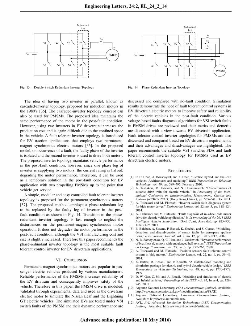
Bolognani et al. reported a fault tolerant drive for PMSMsthat employs a redundant extra inverter leg connected to theneutral point of the motor in the post-fault condition, asshown in Fig. 13 [34]. The proposed inverter is also calleddouble-switch redundant inverter topology since it needs twoextra fuses and electronic switches for the extra inverterleg. The proposed model does not have the DC-link centerpoint balancing issues; however, it needs the neutral point ofthe PMSM [31]. In the post-fault condition, over-current isrequired to maintain the rated output torque, as the averagemotor line voltages is
√3 times less than the healthy condition
[35]. Therefore double switch-redundant inverter topology isunsuitable for EV drivetrain application.
The idea of having two inverter in parallel, known ascascaded-inverter topology, proposed for induction motors inthe 1980’s [36]. The cascaded-inverter topology concept canalso be used for PMSMs. The proposed idea maintains thesame performance of the motor in the post-fault condition.However, using two inverters in EV drivetrain increases theproduction cost and is again difficult due to the confined spacein the vehicle. A fault tolerant inverter topology is introducedfor EV traction applications that employs two permanent-magnet synchronous electric motors [35]. In the proposedmodel, on occurrence of a fault, the faulty phase of the inverteris isolated and the second inverter is used to drive both motors.The proposed inverter topology maintains vehicle performancein the post-fault condition; however, since one phase leg ofinverter is supplying two motors, the current rating is halved,degrading the motor performance. Therefore, it can be usedas a temporary solution in the post-fault condition for EVapplication with two propelling PMSMs up to the point thatvehicle get service.
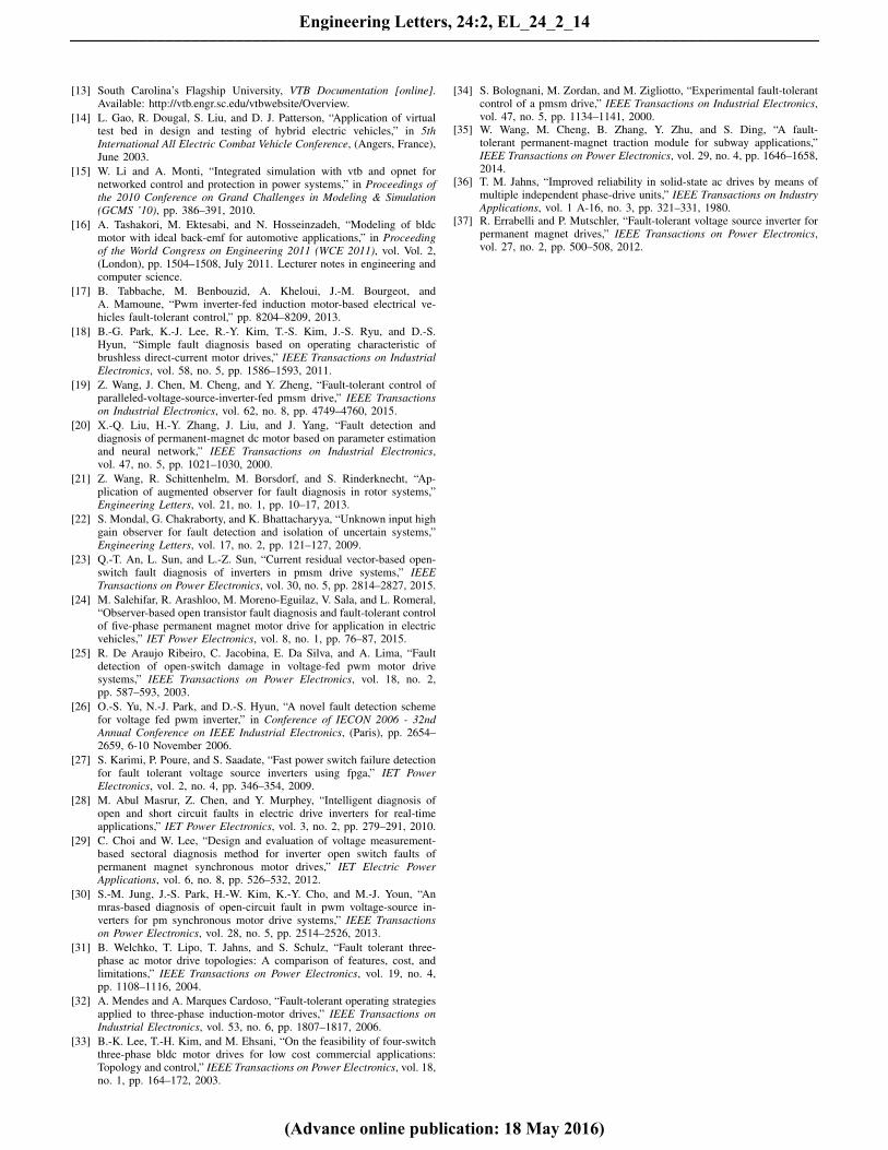
A simple, modular and easy controlled fault tolerant invertertopology is proposed for the permanent-synchronous motors[37]. The proposed method employs a phase-redundant legto be replaced by the faulty leg of inverter in the post-fault condition as shown in Fig. 14. Transition to the phase-redundant inverter topology is fast enough to neglect thedisturbances on the permanent-magnet synchronous motoroperation. It does not degrades the motor performance in thepost-fault condition, although the VSI manufacturing cost andsize is slightly increased. Therefore this paper recommends thephase-redundant inverter topology is the most suitable faulttolerant control inverter for EV drivetrain applications.
VI. CONCLUSION
Permanent-magnet synchronous motors are popular in pas-senger electric vehicles produced by various manufacturers.Reliable performance of the PMSMs increases reliability ofthe EV drivtrain and consequently improves safety of thevehicle. Therefore in this paper, the PMSM drive is modeled,validated through experimental data and used as the drivetrainelectric motor to simulate the Nissan Leaf and the LightningGT electric vehicles. The simulated EVs are tested under VSIswitch faults of the PMSM and their dynamic performance are
Fig. 14. Phase-Redundant Inverter Topology
discussed and compared with no-fault condition. Simulationresults demonstrate the need of fault tolerant control systems inEV drivetrain electric motors to improve safety and reliabilityof the electric vehicles in the post-fault condition. Variousvoltage-based faults diagnosis algorithms for VSI switch faultsin PMSM drives are reviewed and their merits and demeritsare discussed with a view towards EV drivetrain application.Fault tolerant control inverter topologies for PMSMs are alsodiscussed and compared based on EV drivetrain requirements,and their advantages and disadvantages are highlighted. Thepaper recommends the suitable VSI switches FDA and faulttolerant control inverter topology for PMSMs used as EVdrivetrain electric motors.
REFERENCES
[1] C. C. Chan, A. Bouscayrol, and K. Chen, “Electric, hybrid, and fuel-cellvehicles: Architectures and modeling,” IEEE Transaction on VehicularTechnology, vol. 59, pp. 589–597, February 2010.
[2] A. Tashakori, M. Ektesabi, and N. Hosseinzadeh, “Characteristics ofsuitable drive train for electric vehicle,” in Proceeding of the Inter-national Conference on Instrumentation, Measurement, Circuits andSystems (ICIMCS 2011), (Hong Kong,China.), pp. 535–541, Dec 2011.
[3] A. Tashakori and M. Ektesabi, “Inverter switch fault diagnosis systemfor bldc motor drives,” Engineering Letters, vol. 22, no. 3, pp. 118–124,2014.
[4] A. Tashakori and M. Ektesabi, “Fault diagnosis of in-wheel bldc motordrive for electric vehicle application,” in In proceeding of the 2013 IEEEIntelligent Vehicles Symposium, (Gold Coast, Australia), pp. 925–930,June 23-26 2013.
[5] E. Balaban, A. Saxena, P. Bansal, K. Goebel, and S. Curran, “Modeling,detection, and disambiguation of sensor faults for aerospace applica-tions,” IEEE Sensors Journal, vol. 9, no. 12, pp. 1907–1917, 2009.
[6] N. B. Samoylenko, Q. C. Han, and J. Jatskevich, “Dynamic performanceof brushless dc motors with unbalanced hall sensors,” IEEE Transactionson Energy Conversion, vol. 23, no. 3, pp. 752–763, 2008.
[7] A. Tashakori and M. Ektesabi, “Position sensors fault tolerant controlsystem in bldc motors,” Engineering Letters, vol. 22, no. 1, pp. 39–46,2014.
[8] K. Butler, M. Ehsani, and P. Kamath, “A matlab-based modeling andsimulation package for electric and hybrid electric vehicle design,” IEEETransactions on Vehicular Technology, vol. 48, no. 6, pp. 1770–1778,1999.
[9] D. W. Gao, C. Mi, and A. Emadi, “Modeling and simulation of electricand hybrid vehicles,” Proceedings of the IEEE, vol. 95, Issue 4, pp. 729–745, 2007.
[10] Argonne National Laboratory, PSAT Documentation [online]. Available:http://www.transportation.anl.gov/modelingsimulation/PSAT/.
[11] Argonne National Laboratory, Autonomie Documentation [online].Available: http://www.autonomie.net/.
[13] South Carolina’s Flagship University, VTB Documentation [online].Available: http://vtb.engr.sc.edu/vtbwebsite/Overview.
[14] L. Gao, R. Dougal, S. Liu, and D. J. Patterson, “Application of virtualtest bed in design and testing of hybrid electric vehicles,” in 5thInternational All Electric Combat Vehicle Conference, (Angers, France),June 2003.
[15] W. Li and A. Monti, “Integrated simulation with vtb and opnet fornetworked control and protection in power systems,” in Proceedings ofthe 2010 Conference on Grand Challenges in Modeling & Simulation(GCMS ’10), pp. 386–391, 2010.
[16] A. Tashakori, M. Ektesabi, and N. Hosseinzadeh, “Modeling of bldcmotor with ideal back-emf for automotive applications,” in Proceedingof the World Congress on Engineering 2011 (WCE 2011), vol. Vol. 2,(London), pp. 1504–1508, July 2011. Lecturer notes in engineering andcomputer science.
[17] B. Tabbache, M. Benbouzid, A. Kheloui, J.-M. Bourgeot, andA. Mamoune, “Pwm inverter-fed induction motor-based electrical ve-hicles fault-tolerant control,” pp. 8204–8209, 2013.
[18] B.-G. Park, K.-J. Lee, R.-Y. Kim, T.-S. Kim, J.-S. Ryu, and D.-S.Hyun, “Simple fault diagnosis based on operating characteristic ofbrushless direct-current motor drives,” IEEE Transactions on IndustrialElectronics, vol. 58, no. 5, pp. 1586–1593, 2011.
[19] Z. Wang, J. Chen, M. Cheng, and Y. Zheng, “Fault-tolerant control ofparalleled-voltage-source-inverter-fed pmsm drive,” IEEE Transactionson Industrial Electronics, vol. 62, no. 8, pp. 4749–4760, 2015.
[20] X.-Q. Liu, H.-Y. Zhang, J. Liu, and J. Yang, “Fault detection anddiagnosis of permanent-magnet dc motor based on parameter estimationand neural network,” IEEE Transactions on Industrial Electronics,vol. 47, no. 5, pp. 1021–1030, 2000.
[21] Z. Wang, R. Schittenhelm, M. Borsdorf, and S. Rinderknecht, “Ap-plication of augmented observer for fault diagnosis in rotor systems,”Engineering Letters, vol. 21, no. 1, pp. 10–17, 2013.
[22] S. Mondal, G. Chakraborty, and K. Bhattacharyya, “Unknown input highgain observer for fault detection and isolation of uncertain systems,”Engineering Letters, vol. 17, no. 2, pp. 121–127, 2009.
[23] Q.-T. An, L. Sun, and L.-Z. Sun, “Current residual vector-based open-switch fault diagnosis of inverters in pmsm drive systems,” IEEETransactions on Power Electronics, vol. 30, no. 5, pp. 2814–2827, 2015.
[24] M. Salehifar, R. Arashloo, M. Moreno-Eguilaz, V. Sala, and L. Romeral,“Observer-based open transistor fault diagnosis and fault-tolerant controlof five-phase permanent magnet motor drive for application in electricvehicles,” IET Power Electronics, vol. 8, no. 1, pp. 76–87, 2015.
[25] R. De Araujo Ribeiro, C. Jacobina, E. Da Silva, and A. Lima, “Faultdetection of open-switch damage in voltage-fed pwm motor drivesystems,” IEEE Transactions on Power Electronics, vol. 18, no. 2,pp. 587–593, 2003.
[26] O.-S. Yu, N.-J. Park, and D.-S. Hyun, “A novel fault detection schemefor voltage fed pwm inverter,” in Conference of IECON 2006 - 32ndAnnual Conference on IEEE Industrial Electronics, (Paris), pp. 2654–2659, 6-10 November 2006.
[27] S. Karimi, P. Poure, and S. Saadate, “Fast power switch failure detectionfor fault tolerant voltage source inverters using fpga,” IET PowerElectronics, vol. 2, no. 4, pp. 346–354, 2009.
[28] M. Abul Masrur, Z. Chen, and Y. Murphey, “Intelligent diagnosis ofopen and short circuit faults in electric drive inverters for real-timeapplications,” IET Power Electronics, vol. 3, no. 2, pp. 279–291, 2010.
[29] C. Choi and W. Lee, “Design and evaluation of voltage measurement-based sectoral diagnosis method for inverter open switch faults ofpermanent magnet synchronous motor drives,” IET Electric PowerApplications, vol. 6, no. 8, pp. 526–532, 2012.
[30] S.-M. Jung, J.-S. Park, H.-W. Kim, K.-Y. Cho, and M.-J. Youn, “Anmras-based diagnosis of open-circuit fault in pwm voltage-source in-verters for pm synchronous motor drive systems,” IEEE Transactionson Power Electronics, vol. 28, no. 5, pp. 2514–2526, 2013.
[31] B. Welchko, T. Lipo, T. Jahns, and S. Schulz, “Fault tolerant three-phase ac motor drive topologies: A comparison of features, cost, andlimitations,” IEEE Transactions on Power Electronics, vol. 19, no. 4,pp. 1108–1116, 2004.
[32] A. Mendes and A. Marques Cardoso, “Fault-tolerant operating strategiesapplied to three-phase induction-motor drives,” IEEE Transactions onIndustrial Electronics, vol. 53, no. 6, pp. 1807–1817, 2006.
[33] B.-K. Lee, T.-H. Kim, and M. Ehsani, “On the feasibility of four-switchthree-phase bldc motor drives for low cost commercial applications:Topology and control,” IEEE Transactions on Power Electronics, vol. 18,no. 1, pp. 164–172, 2003.
[34] S. Bolognani, M. Zordan, and M. Zigliotto, “Experimental fault-tolerantcontrol of a pmsm drive,” IEEE Transactions on Industrial Electronics,vol. 47, no. 5, pp. 1134–1141, 2000.
[35] W. Wang, M. Cheng, B. Zhang, Y. Zhu, and S. Ding, “A fault-tolerant permanent-magnet traction module for subway applications,”IEEE Transactions on Power Electronics, vol. 29, no. 4, pp. 1646–1658,2014.
[36] T. M. Jahns, “Improved reliability in solid-state ac drives by means ofmultiple independent phase-drive units,” IEEE Transactions on IndustryApplications, vol. 1 A-16, no. 3, pp. 321–331, 1980.
[37] R. Errabelli and P. Mutschler, “Fault-tolerant voltage source inverter forpermanent magnet drives,” IEEE Transactions on Power Electronics,vol. 27, no. 2, pp. 500–508, 2012.