REVIEW Solid-State Gas Sensors: A Review A. M. Azad, S. A. Akbar,* S. G. Mhaisalkar, ~ L. D. Birkefeld,** and K. S. Goto b Department of Materials Science and Engineering, The Ohio State University, Columbus, Ohio 43210 ABSTRACT During the past three decades, gas sensors based either on the surface characteristics or the bulk electrolytic properties of ceramics, have been the subject of extensive research and development. The application of these sensors range from air-to-fuel ratio control in combustion processes such as in automotive engines and industrial furnaces to the detection of leakage of inflammable and toxic gases in domestic and industrial environments. While the solid-state physical sensors, measuring pressure, temperature, and other physical parameters have been commercially successful, less success has been achieved by their chemical analogs, to measure moderate to very low concentrations of gases of importance. These gases include: 02, H2, CO, CO2, NOx, SO=, propane, methane, ethanol, and so on. The semiconductor-based chemical sensors owe their popularity to their small size, simple operation, high sensitivity, and relatively simple associated electronics. How- ever, most of them still suffer from nonselectivity. They also have poor shelf-life and are relatively less stable at higher temperatures. The sensing characteristics and performance of some of the solid-state gas sensors are reviewed in this paper, together with their sensing mechanism, which still is a gray area and has not been fully understood. The recent emergence of concern over environmental pollution and effleieney in a variety of combustion pro- cesses and of increased awareness over a need to monitor potentially hazardous gases has stimulated substantial re- search and development in the field of gas sensors. These gases include, CO, CO2, NOx (x = 0.5, 1, and 2), SOx (x = 2 and 3), a fraction of unburned hydrocarbons [ineluding liquefied petroleum gas (LPG) also known as cooking or town gas] and hydrogen. Requirements to detect and moni- tor these gases has already led to the development of a wide variety of devices and methods, as evideneed by a large number of instruments now available commercially. The majority of these detection and/or metering devices involve the application of surface or bulk chemical and physical properties of materials and can, therefore, be called solid- state chemical sensors. 1-5 However, before addressing the topic of these gas sensors, it is appropriate to briefly outline some of the environmental concerns. LP gas can form explosive mixture with ambient air and ean lead to personal injury upon continuous exposure, even in small concentrations. A number of industrially impor- tant eatalytie processes require either producer gas (CO + H2) in various compositions or H2 and CO separately as feed stocks. The producer gas is synthesized by the steam re- forming of natural gases and other hydrocarbons under conditions of high temperatures and pressures. The acci- dental eseape or leak of either CO or H2 from sueh a high temperature and pressure system can be a source of explo- sion and health hazard. The combustion of hydrocarbon fuels is a widely used method of obtaining useful energy in various industries. Burning of fossil fuel in the "lean-burn combustion" man- ner is regarded as the most fuel and energy efficient mode of fuel utilization, since under these eonditions, the hydro- carbons in the fuel are fully eonverted into CO2 and H20. However, the compositional analysis of the flue gases in most of the combustion furnaces, indicates the presence of CHJCO/CO2/H2 in the final reaction product, in accor- dance with the thermodynamic predictions under the con- ditions of these processes. This could be attributed to the occurrence of the following reaetions side-by-side CHx + (1 + x/4) 02 --> CO2 + (x/2) H20 [1] * Electrochemical Society Active Member. ** Electrochemical Society Student Member. 'Present address: IMT, Nanyang Technological University, Singapore 2263. ~Present address: 5-27-5, Honcho, Koganei City, Tokyo 184, Japan. CHx + H20 --> CO + (1 + x/2) H2 [2] CH= + CQ -9 2CO + (x/2) H2 [3] Thus, if there is excess fuel (fuel-rich region), CO would be the main residue product of combustion, together with a small amount of hydrogen, while if there is excess air (fuel- lean region), free oxygen would be present in the exhaust gas, together with carbon dioxide and steam. This situation exists in most conventional fossil-fuel-fired furnaces and automobile engines. At this point, it is worth mentioning that in most of the under-developed and developing coun- tries, coal is stillthe most viable source of energy. At the same time, it is also the biggest source of air pollutants. Coal, when fed into furnaces, is firstdistilled, giving out gaseous hydrocarbons, CO, H2 etc.,leaving behind carbon, which on insufficient combustion produces smoke. 6'7 Addi- tionally, during combustion SO= and NO= are formed, both of which contribute to air and soil pollution by way of "acid rain." Oxides of sulfur (SO2 and SQ) are produced during the combustion of fossil fuels and during smelting of many nonferrous ores. ~'9It is necessary to monitor the concentra- tion of these gases escaping into the atmosphere, both for process control and reduction of environmental pollution by way of forming acidic precipitant. Nitrogen oxides, NO and NO2, (generally represented as NO=) are the most com- mon and dangerous pollutants of the atmosphere. I~ Nitro- gen oxides are produced during the burning process (mainly energy production and transport) under high tem- peratures and do not decompose easily at room tempera- tures. Nitric oxide (NO) constitutes about 98% of the total NO= in the automobile emission1~; though not the major emittant in exhaust gases, it is one of the most difficult to control. Together with the oxides of sulfur, these com- pounds contribute to the formation of acid rain, which ex- erts very harmful environmental effects. Photolytic decom- position of NO2 by cosmic radiations results in ozone formation, which when combined with hydrocarbons, forms smog. I~ Anthropogeneous sources of NO= are of more concern than the natural ones, because they are localized and lead to high concentration of this pollutant in am- bient air. The ultimate accumulation of carbon dioxide by fuel burning under "lean" conditions in combustion furnaces and in automobile engines, has been anticipated as the main reason for "global warming" and "greenhouse ef- fects." ~2 Rapid increase in deforestation and urbanization 3690 J. Electrochem. Soc., Vol. 139, No. 12, December 1992 The Electrochemical Society, Inc. Downloaded 16 Apr 2012 to 131.183.0.122. Redistribution subject to ECS license or copyright; see http://www.ecsdl.org/terms_use.jsp
Transcript
REVIEW
Solid-State Gas Sensors: A Review A. M. Azad, S. A. Akbar,* S. G. Mhaisalkar, ~ L. D. Birkefeld,** and K. S. Goto b
Department of Materials Science and Engineering, The Ohio State University, Columbus, Ohio 43210
ABSTRACT
During the past three decades, gas sensors based either on the surface characteristics or the bulk electrolytic properties of ceramics, have been the subject of extensive research and development. The application of these sensors range from air-to-fuel ratio control in combustion processes such as in automotive engines and industrial furnaces to the detection of leakage of inflammable and toxic gases in domestic and industrial environments. While the solid-state physical sensors, measuring pressure, temperature, and other physical parameters have been commercially successful, less success has been achieved by their chemical analogs, to measure moderate to very low concentrations of gases of importance. These gases include: 02, H2, CO, CO2, NOx, SO=, propane, methane, ethanol, and so on. The semiconductor-based chemical sensors owe their popularity to their small size, simple operation, high sensitivity, and relatively simple associated electronics. How- ever, most of them still suffer from nonselectivity. They also have poor shelf-life and are relatively less stable at higher temperatures. The sensing characteristics and performance of some of the solid-state gas sensors are reviewed in this paper, together with their sensing mechanism, which still is a gray area and has not been fully understood.
The recent emergence of concern over environmental pollution and effleieney in a variety of combustion pro- cesses and of increased awareness over a need to monitor potentially hazardous gases has stimulated substantial re- search and development in the field of gas sensors. These gases include, CO, CO2, NOx (x = 0.5, 1, and 2), SOx (x = 2 and 3), a fraction of unburned hydrocarbons [ineluding liquefied petroleum gas (LPG) also known as cooking or town gas] and hydrogen. Requirements to detect and moni- tor these gases has already led to the development of a wide variety of devices and methods, as evideneed by a large number of instruments now available commercially. The majority of these detection and/or metering devices involve the application of surface or bulk chemical and physical properties of materials and can, therefore, be called solid- state chemical sensors. 1-5 However, before addressing the topic of these gas sensors, it is appropriate to briefly outline some of the environmental concerns.
LP gas can form explosive mixture with ambient air and ean lead to personal injury upon continuous exposure, even in small concentrations. A number of industrially impor- tant eatalytie processes require either producer gas (CO + H2) in various compositions or H2 and CO separately as feed stocks. The producer gas is synthesized by the steam re- forming of natural gases and other hydrocarbons under conditions of high temperatures and pressures. The acci- dental eseape or leak of either CO or H2 from sueh a high temperature and pressure system can be a source of explo- sion and health hazard.
The combustion of hydrocarbon fuels is a widely used method of obtaining useful energy in various industries. Burning of fossil fuel in the "lean-burn combustion" man- ner is regarded as the most fuel and energy efficient mode of fuel utilization, since under these eonditions, the hydro- carbons in the fuel are fully eonverted into CO2 and H20. However, the compositional analysis of the flue gases in most of the combustion furnaces, indicates the presence of CHJCO/CO2/H2 in the final reaction product, in accor- dance with the thermodynamic predictions under the con- ditions of these processes. This could be attr ibuted to the occurrence of the following reaetions side-by-side
CHx + (1 + x/4) 02 --> CO2 + (x/2) H20 [1]
* Electrochemical Society Active Member. ** Electrochemical Society Student Member. 'Present address: IMT, Nanyang Technological University,
Singapore 2263. ~ Present address: 5-27-5, Honcho, Koganei City, Tokyo 184,
Japan.
CHx + H20 --> CO + (1 + x/2) H2 [2]
CH= + C Q -9 2CO + (x/2) H2 [3]
Thus, if there is excess fuel (fuel-rich region), CO would be the main residue product of combustion, together with a small amount of hydrogen, while if there is excess air (fuel- lean region), free oxygen would be present in the exhaust gas, together with carbon dioxide and steam. This situation exists in most conventional fossil-fuel-fired furnaces and automobile engines. At this point, it is worth mentioning that in most of the under-developed and developing coun- tries, coal is still the most viable source of energy. At the same time, it is also the biggest source of air pollutants. Coal, when fed into furnaces, is first distilled, giving out gaseous hydrocarbons, CO, H2 etc., leaving behind carbon, which on insufficient combustion produces smoke. 6'7 Addi- tionally, during combustion SO= and NO= are formed, both of which contribute to air and soil pollution by way of "acid rain."
Oxides of sulfur (SO2 and SQ) are produced during the combustion of fossil fuels and during smelting of many nonferrous ores. ~'9 It is necessary to monitor the concentra- tion of these gases escaping into the atmosphere, both for process control and reduction of environmental pollution by way of forming acidic precipitant. Nitrogen oxides, NO and NO2, (generally represented as NO=) are the most com- mon and dangerous pollutants of the atmosphere. I~ Nitro- gen oxides are produced during the burning process (mainly energy production and transport) under high tem- peratures and do not decompose easily at room tempera- tures. Nitric oxide (NO) constitutes about 98% of the total NO= in the automobile emission1~; though not the major emittant in exhaust gases, it is one of the most difficult to control. Together with the oxides of sulfur, these com- pounds contribute to the formation of acid rain, which ex- erts very harmful environmental effects. Photolytic decom- position of NO2 by cosmic radiations results in ozone formation, which when combined with hydrocarbons, forms smog. I~ Anthropogeneous sources of NO= are of more concern than the natural ones, because they are localized and lead to high concentration of this pollutant in am- bient air.
The ultimate accumulation of carbon dioxide by fuel burning under "lean" conditions in combustion furnaces and in automobile engines, has been anticipated as the main reason for "global warming" and "greenhouse ef- fects." ~2 Rapid increase in deforestation and urbanization
3690 J. Electrochem. Soc., Vol. 139, No. 12, December 1992 �9 The Electrochemical Society, Inc.
Downloaded 16 Apr 2012 to 131.183.0.122. Redistribution subject to ECS license or copyright; see http://www.ecsdl.org/terms_use.jsp
has made this problem more acute than ever. It is reported that the greenhouse effect makes the Earth's surface 33°C warmer than it would be otherwise. ~3 From space, the Earth would appear to be at an average temperature of -18°C. This is because long wavelength radiations from the Earth's surface are absorbed by clouds and greenhouse gases, and much of that is back-radiated toward the Earth, making the true surface temperature about 15°C on aver- age. The two largest contributors to the greenhouse effect are water vapor and carbon dioxide. Other "gases which contribute an additional 5 0 % of the warming of CO2 itself, include methane, nitrous oxides, ozone, and ehlorofluoro- carbons (CFCs). 14 Arrhenius ~5 had estimated a 4-6°C in- crease in the average temperature due to CO2 doubling in the atmosphere. Some of the numerical models show that for CO2 doubling, European temperatures could increase by 2-6°C in the summer and by 4-16°C in the winter) 6 An- other model predicts summer temperatures in the U.S. warmer up to 8°CY Higher growth rates of plants under increased CO2 may help, as the plants will incorporate more CO2, but increased radiation due to the thinning of ozone layer may substantially nullify that benefit.
In view of these facts, monitoring the progress and con- trol of combustion processes and from the viewpoints of anthropogeneous, industrial, and automobile exhaust pol- lution control, reliable and long-life sensors capable of de- tecting and measuring gases in the ambient and at the gen- erating source are needed. Techniques such as gas chromatography and infrared absorption are widely used for accurate analysis and detection of these gases. How- ever, installation of these conventional instruments is costly, requires a sampling system and complicated maintenance, and in si tu continuous monitoring in most gaseous environments becomes time consuming and unre- alistic. During the past three decades, rapid growth has been seen in the sensor technology encompassing a broad spectrum covering safety, fuel economy, pollution control, medical engineering, and industrial processes. Most of the advances in the gas sensors (except, perhaps, for O2) has been sustained by development based on rather empirical methods, and consequently a reasonable understanding of the gas sensing mechanisms is lacking in the published lit- erature. Moreover, these sensors are often subject to deteri- oration with time (low shelf-life) and also to interference by other coexisting gases. From a practical standpoint, a gas sensor is useful only if it can detect the desired active component in the presence of noninterfering background constituent(s). That is, the sensor must be selective and must function according to the acceptable and controllable levels of sensitivity and detectability. Much work is being done to mass-produce sensitive, selective, reliable, and in- expensive sensors, capable of detecting even low concen- trations (tenths or hundredths of a percent) of gases such as CO, CO2, 02, H2, NO~, SO=, natural gases (CH4), propane (C3H8), alcohol (C~H~OH) and so onY -3°
The objective of this paper is to review the developing field of chemical sensors, with special emphasis on those based on semiconducting materials, for toxic gases and to analyze the performance and basic working principles of these sensors.
Solid-State Gas Sensors Based on the sensing principles, gas sensors can be
classified in the following three categories: (i) solid elec- trolyte gas sensors, (it) catalytic combustion gas sensors, and (iii) semiconductor gas sensors.
Solid electrolyte sensors . - -The solid-electrolyte-based sensors owe their usefulness to the exceptionally high ionic conductivity of the solid electrolyte material in the temper- ature range of 773 to 1573 K. These have only one mobile species and, in the case of oxide systems based on stabilized zirconia, they find wide applications. An oxygen sensor works on the principle of a concentration cell in which oxygen ion conductor (stabilized zirconia) acts as the solid electrolyte and also as a separator for the two compart-
ments with gaseous mixtures having different oxygen po- tentials or partial pressures. The galvanic cell
P~2 (ref.), Pt/Y203-ZrO2/Pt, P62 (test) [4]
would develop an open-circuit electrochemical potential (EMF) by virtue of the following half-cell reactions
4e + O2 (Po2) --~ 2 02- [5a]
and 2 02_ --> 02 (P~2) + 4e-
resulting in the net cell reaction
02 (Po2) -~ 02 (Po2)
[5b]
[6]
According to the Nernst equation, the EMF of the cell could be represented as
E = (RT/4F) In (P~2/P~2) [7]
The Po~ in the test gas could thus be evaluated by measur- ing the equilibrium EMF (E) at a given temperature, T.
Oxygen sensors based on the above principle are widely used for combustion control in heat-treatment furnaces, glass tank furnaces, ceramic kilns, boilers, oil and gas stoves and for oxygen control in steel and copper melts. 31'32 However, the largest single use (~ 7 5 %) of oxygen sensors is in the automobiles to improve the fuel efficiency and to control CO and NOt content in the exhaust gas. 31'33 A single manufacturer (Nippon-Denso) is reported to be producing nearly 100,000,000 zirconia oxygen sensors per year, cover- ing 70% of the Japanese market. 34 The schematic of such a zirconia-based sensor is shown in Fig. 1. The basic design consists of a yttria-stabilized zirconia ceramic thimble, which is coated wi th porous plat inum electrode on both sides. The sensor is located in the exhaust pipe, so that the exterior of the sensor is exposed to the exhaust gases and the inside is exposed to the air reference. Sometimes Y203 is partially replaced by MgO to lower the cost and increase the thermal shock resistance. 3~ The advantages of these sensors are: (i) quick and continuous monitoring, (it) the sensor output being an electrical signal, can be easily mod- ulated for electronic control device, (iii) accuracy, (iv) sim- ple design, (v) weak temperature dependence, and (vi) wide range of zirconia compositions. 36
These sensors, however, measure the equilibrium partial pressure of oxygen and not the true oxygen concentration, and they exhibit very poor sensitivity when the difference between Po2 and Po2 is small. 31,37 It may be noted that the response of the sensor (Fig. 2), where air/fuel (A/F) ratio is expressed as a mass ratio, does not entirely follow the Nernst law (Eq. 7), with the voltage being 15% lower in rich fuel/air mixtures and 10 % higher in lean mixtures. 38'39 This departure could be due to the fact that in a car engine, the working environment is very demanding with a life-time of several thousand hours, rapidly changing temperature, high velocity gases containing fine abrasive particles, and lead compounds (even in nominally lead-free fuels), which can poison the electrodes. Thus, in order to improve the performance and life-time of the sensors, the electrolyte is usually protected with a porous plasma ceramic coating (of spinel, alumina, or metallic shroud), which acts as a gas diffusion barrier and helps to minimize the degradation of outer electrode by the constituents of the exhaust gases.
Substantial progress has been made in recent years in overcoming the above-mentioned limitations. The most significant of these has been the development of diffusion- controlled limiting-current-type oxygen sensors based on the conventional stabilized zirconia (YSZ) as well as the tetragonal zirconia polycrystal (TZP) electrolytes. 4°'4' The latter appear to be more attractive, both electrochemically and mechanically, due to their higher oxygen conductivity at lower temperatures and greater durability towards ther- mal shocks. 41 The basic configuration of the limiting cur- rent (also known as polarographic or amperometric 42-4~) sensors is shown in Fig. 3. The zireonia pellet is coated with porous platinum electrodes_ The cathode is enclosed except for a small hole by a porous layer of zirconia, spinel or
Downloaded 16 Apr 2012 to 131.183.0.122. Redistribution subject to ECS license or copyright; see http://www.ecsdl.org/terms_use.jsp
3692 J. Electrochem. Soc., Vol. 139, No. 12, December 1992 �9 The Electrochemical Society, Inc.
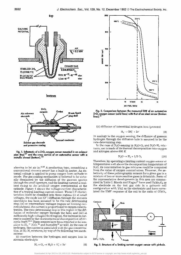
top
I /
~ . ! ~ ~ ; ~ . EXHAUST~AS STABILIZED ZrO 1 / ~ ~. ;~ EOUILIBRIUU P~ E L E C T R O ~ ~ . . . . . . . . . . . 02 Pt CAT.+,L~ST ~ - - - - - - ~ ~ r +0-t+-10-46 otto ELECTRODES ~ LEAN: 10 -2 aim
Fig. 1. Schematic of a Zr02 oxygen sensor mounted in an exhaust pipe (top)m7 and the cross section of an automotive sensor with a metallic shroud (bottom). 188
alumina to let air in. 46-+9 A production type, resembling a conventional zirconia sensor has a built-in heater. An ex- ternal voltage is applied to pump oxygen from cathode to anode. The gas sensing mechanism is believed to be virtu- ally dominated by the diffusion of the gaseous species through the small apertur% and the limiting current is real- ized owing to the artificial oxygen overpotential at the cathode. Figure 4 shows the voltage-current characteris- tics of a typical limiting-current sensor. These I-V charac- teristics could be classified into three regions (i) at small voltages, the oxide ion (02 ) diffusion through the zirconia electrolyte has been assumed to be the rate-determining step; (if) at intermediate voltages (regime of limiting cur- rent plateau), the current is proportional to oxygen concen- tration. The rate-determining step in this region is the dif- fusion of molecular oxygen through the hole; and (iii) at sufficiently high voltages (third region), the increase in cur- rent is caused by the electrochemical decomposition of zir- conia itself. 4~ These sensors have been reported to be sen- sitive to H2, 50 N20, 5t and humidity 52 as well. In the case of hydrogen, the current is associated with the gas concentra- tion, in H2-N2 mixtures, by way of the following two mech- anisms:
(i) reaction between the hydrogen and oxygen ions in zirconia electrolyte
H2 + Oo --> H20 + Vo + 2e- [8]
I000
800
600 ii
!
4O0
200
3~'0"C 480 "C I
I
STOIGH 15 16
AIR/FUEL RATIO
Fig. 2. Comparison between the measured EMF of an automotive Zr02 oxygen sensor (solid lines) with that of an ideal sensor (broken lines). 3v
(if) diffusion of interstitial hydrogen ions (protons)
H~ --> 2H: + 2e [9]
In analogy to the oxygen sensing, the diffusion of gaseous hydrogen through the diffusion hole is assumed to be the rate-determining step.
In the case of N20-sensing in N20-O2 and N20-N2 mix- tures, use is made of its thermal decomposition into oxygen and nitrogen above 600 K
N20 --> N2 + 1/2 O5 [i0]
Therefore, by operating a limiting current oxygen sensor at temperatures well above the decomposition temperature of N20, its concentration in gas mixtures could be computed from the value of oxygen concentration. However, the se- lectivity of these polarographic sensors for a given gas in a mixture of two or more reactive gases is debatable. Some of the representative developments in this area are summa- rized in Table I. Maeda and Nagao 53 have used ZrM0208 as the electrode on the test gas side in a galvanic cell configuration with YSZ as the electrolyte and have corre- lated the EMF response of the cell to the ratio of CO/Q,
( )L C a i ~ c i~-H~
I l iili ii i+i+i+l I ~ii~ ~il ~ t ~ l li!H+i!iiiil ............... V|
r:-:.'.:.':-.'.': . , ' . - '~ ! ! !~ . : . ........ ~ - i h
�9 ~[mmCurrvm T
Fig. 3. Structure of a limiting current oxygen sensor with pinhole.
Downloaded 16 Apr 2012 to 131.183.0.122. Redistribution subject to ECS license or copyright; see http://www.ecsdl.org/terms_use.jsp
J. Electrochem. Soc., Vol. 139, No. 12, December 1992 �9 The Electrochemical Society, Inc.
Table I. Solid electrolyte sensors.
3693
Sensor Composition T (~ Mechanism/Remarks Ref.
CO YSZ + ZrMozO~ electrode 500 Ratio of CO/O~ is measured 53 Mechanism not established
H ~ / H ~ O CaZr0.gIn0.~O~_ ~ solid electrolyte 700 Proton conduction 173 Ca0 ~Sr0.~CoQ standard
02 YSZ 450 Limiting current type 37 N~O YSZ oxygen sensor 500 Applicable only to N~O/ 50
inert gas mixtures H~ YSZ oxygen sensor 500 Applicable only to H~/inert 51
gas mixtures O~ YSZ 650-1000 Pt + CeQ electrode material 174
for high temps O~ YSZ/PrO~, T bQ electrodes 800-1000 Good alternative for Pt 175
at high temperature Humidity/H2 SrCe0.~Yb0.0~Q 400-1000 Protonic conductor 58 H~ Antimonic acid 0-50 Protonic conduction 176 CO~ KzCO~ electrolyte, 300-750 Conduction through 101
(CaCO~ + CaO) reference carbonate ion CO~ Nasicon with Li-based mixed carbonate electrodes 500 Working mechanism not clear 103 CO~ Li§ lithium aluminotitano-phosphate 650 80 ppm to 1% CO~ detection 104, 105
as electrolyte
expressed in terms of the magnitude of incomplete combus- tion. Although the sensing mechanism of this sensor is not yet understood or theoretically explained, a further under- standing and development of these or similar electrode ma- terials might result in reliable combustion control sensors.
Yet another gas sensor for the direct, continuous, and fast measurement of hydrogen and/or steam concen- trations in high-temperature gases, in situ, based on a high temperature proton conductor as a solid electrolyte, holds promise. The principle of hydrogen concentration cell is same as that of the solid-state oxygen cells and is shown in Fig. 5. The differential hydrogen partial pressures across the electrolyte give rise to a theoretical EMF repre- sented by
E (RT/2F) in i~(~iD(m~ [ii] = \ ~ H 2 / X ~ 2 /
where , ~m a n d D(~s) o ~ the p a r t i a l p ressu res of h y d r o g e n in ~ H 2 ~H2 ~
c o m p a r t m e n t I a n d II, respect ively . A n u m b e r of good p ro - ton c o n d u c t i n g sol ids (such as HUO2PO4 4H20, H3Mo~2PQ0 �9 29 H20, NH~ s u b s t i t u t e d - ~ - g a l l i a a n d ~"-a lu - mina , H30 § s u b s t i t u t e d [~- a n d [~"-aluminas, etc.), have b e e n inves t iga ted , b u t t h e y a re u n s t a b l e a t h i g h t e m p e r a t u r e s a n d decompose w i t h i n v a r i a b l e l i b e r a t i o n of wa te r . N o n e of these a re s t ab l e above a b o u t 673 K. I w a h a r a a n d cowork - ers ~-5~ h a v e f o u n d t h a t the p e r o v s k i t e - t y p e oxides b a s e d on SrCeQ and BaCeO~ with partial substitution of Ce 4+ by some of the rare-earth ions (Ln~+), are excellent high tem- perature p r o t o n conduc tors . SrCe0.9~Yb0.0~Q_~ a n d BaCe09Nd0 ~O34 b e l o n g to th i s class of c o n d u c t o r s (5 is the oxygen def ic iency pe r u n i t cell of t h e p e r o v s k i t e - t y p e ox- ide). The E M F re sponse of the h y d r o g e n sensor as a i u n c -
30
( ) X y S C n r174162162 I i i i ion
30 %
E -~ 20
,.-n
,20%
1 0 %
~ , k %
~ J ,-'o I I I l 2
Voltage( V )
| i
Fig. 4. Current-voltage characteristics of a limiting current type oxygen sensor at 773 K for various oxygen concentrations (v/o O2) in O2-N2 gas mixtures./89
tion of hydrogen partial pressure, in the range from 473 to 1173 K is shown in Fig. 6. It was found that the relation between the EMF and PH2 was Nernstian down to about 10 3 atm of H2 in the entire temperature range.
The proton conduction in these oxides has been envis- aged to be a consequence of electron holes, initially present in the crystal as native intrinsic defects) ~ It is believed that the holes and the counter oxygen ion vacancies play an important role in the formation of hydrogen ions within the lattice and that the conduction is not influenced by the grain boundaries but by the bulk of the crystal itself. Other materials such as Cu20, 59 ThO2-based, 6~ and LaYO3- based 61 oxides, have also been studied, but their proton conduetivities are much lower than those of SrCeO~- or BaCeO~-based oxides. Moreover, the conductivity meas- urements on Y203 6~ and l(TaO 3 ~3 also have shown these
o o e" e"
.
H 2 ~ 2I-I+ + 2r 2I-1 + + 2 e ' ~ H 2
Fig. 5. Working concept of a hydrogen concentration cell. s8
200, I i i I 1 I 1 i i i i l ] i 1 i i i i i
7~ 8O0 900"C
,, 100 X
W
511
0 10 10 10 0
~ j ~ Partial Pressure, P~(|II / a t
Fig. 6. EFM response of the galvanic sensor, H2 (P.2 = 1 atm), Pt/BaC~.~Ndo.loO3 JPt , H2 § Ar. The solid lines represent the theo- retical EMF, given by Eq. 11 at the respective temperature. ~
Downloaded 16 Apr 2012 to 131.183.0.122. Redistribution subject to ECS license or copyright; see http://www.ecsdl.org/terms_use.jsp
3694 J. Electrochem. Soc., Vol. 139, No. 12, December 1992 �9 The Electrochemical Society, Inc.
compounds to be potential candidates for use as hydrogen sensors.
There is no report yet in the published literature, regard- ing the development of solid-state NO~ sensors. However, by making use of the decomposition characteristics of NO and NO2, indirect measurement can be envisaged in terms of oxygen concentration by using limiting current-type cells. Gur and Huggins 6~ had studied the decomposition of NO into nitrogen and oxygen on 8 mole percent (m/o) scan- dia-stabilized zirconia at 117 3 K according to the reaction
NO -~ 1/2 N~ + 1/2 O2 [12]
The oxygen concentration from the i-V characteristic of the amperometric sensor could be used to compute the NOx concentration.
Another area of application of solid electrolytes is the development of SO~ sensors. However, the measurement of sulfur or sulfur oxides (SO2 and SOs) is not as straightfor- ward as the detection and measurement of oxygen, since the electrolyte are neither as stable nor as conducting. Schmalzried ~ first proposed sulfur sensors based on CaF2 (fluoride ion conductor) and stabilized zirconia. Because of the complicated nature of electrode reactions, however, the at tainment of equilibrium was sluggish and incomplete. Since then, several modifications of the electrolytes, in- cluding those based on CaS + CaO-ZrO2 and Na~S + ~-alu- mina have been usedfi 5-7~ In the case of SO= measurements, ~-alumina, 71'72 Nasicon, ~3-7~ and alkali metal sulfates 76-91 have been widely used.
Salzano and Newman 9~ were the first to use a sulfate electrolyte for the measurement of Pso2 in gases, employing a Li~SO~-Na~SO~-K2SO~-based molten salt electrolyte. However, the high chemical reactivity of molten salts with the electrodes as well as with the container material, to- gether with the need to frequently monitor the change (if any) in the reference concentration, limits the application of such molten salt electrolytes. On the other hand, the solid alkali-metal sulfates are good ionic conductors, with exceptionally high conductivities (typically at 973 K, 4 x 10 -~, 2 x 10 -~ and 1.8 ~2 -~ cm -~ for K2SQ, 9~ Na~SQ, a~ and LisSOm, ~ respectively). However, alI of these sulfates un- dergo phase transformations attended by large enthalpy and volume changes. As a result, mierocraeks are generated in the electrolyte, causing permeation of the gas. Lithium sulfate has a very large enthalpy change a.t the transforma- tion temperature and causes substantial gas permeation. Therefore, Li~SO~ is not a suitable electrolyte. On the other hand, potassium sulfate exhibits the lowest conductivity due to the larger ionic radius of the potassium ion. From the point of view of conductivity, transformation enthalpy, phase stability, and sinterability, sodium sulfate appears to be the most promising candidate as the electrolyte for SOx sensors. The electrical and thermal properties of alkali metal sulfates could be appreciably improved by doping with compounds of aliovalent cations such as, Y~(SO~)a and SiQ. 9~ Unti l recently, plat inum gauzes have been used in the test ga s chamber to accelerate SO2 oxidation to SO~. In addition, p la t inum is also sputtered on both the surfaces of the electrolyte. In view of its proven catalytic property to- wards the oxidation of SO2 to SOs in sulfuric acid manufac- turing, Imanaka et al. employed V205 mixed with the alkali sulfate based-electrolytes as the catalyst instead of Pt gauze and the sputtered Pt. ~ It was found that since these sulfates easily form solid solution with V~O5 without dete- rioration of their electrical and thermal characteristics, V~Oa mixing is one of the ways to improve electrolyte properties.
At high oxygen pressures, the sulfates of the alkali metals are thermodynamically stable ~~ and can be used to detect sulfur dioxide potentials in gaseous environments. The sulfate ion effectively dissociates into SO~ and oxygen according to the equation
SO4 ~- ---> SO2 + O~ + 2e- [13]
and the EMF can be expressed by
E = ( R T / Z F ) In (p~/p;~) + ( R T / Z F ) in (P~oJP;oO [14]
If the oxygen partial pressure is fixed at both the electrodes (e.g., Po~ = 0.21 atm), the EMF is given by the ratio of partial pressures of sulfur dioxide alone, in the two compartments of the galvanic cell. In the case of SO3, the following equi- l ibrium is assumed to exist at the gas-electrode/electrolyte interface
S03 + 1/2 02 + 2e- -~ SO~- [15]
for which the open-circuit voltage may be written as
E = ( R T / Z F ) In ~r~"ln~'m~o~, o2J T• ( R T / Z F ) in (P~o3/P~o3) [16]
Though reliable, the gaseous reference electrode is difficult to maintain and requires ways of monitoring the gas compositions precisely. These problems could be over- come by using a metal/metal-sulfate buffer mixture as the reference electrode, having obvious advantages with re- spect to chemical and mechanical stability and design sim- plicity. The most successful solid reference electrode for a S Q and/or SO3 sensor is the Ag-Ag2SO4 mixtureY 97 The Ag-S-O system is unique in that silver and Ag2SQ exist as the adjacent equilibrium phases, in contrast to the usually encountered situation where an oxide phase invariably separates the metal from the corresponding sulfate. This simplifies the electrode processes to a great extent, making the reactions leading to equilibrium, very facile.
Recently, Jacob et al. 98 have reported the use of CaF2 electrolyte along with CaSO4 as the auxiliary electrode for SO= measurements. However, the response was found to be very sluggish, suggesting the approach to equilibrium in this configuration to be very slow. In the case where Nasi- con and ]3-alumina have been employed for SO= measure- ments, it was assumed that sodium sulfate forms on the surface of these electrolytes. 7s Nevertheless, once a layer of Na2SO4 is formed, the rate of reaction is slow and since Na2SO, is a sodium ion conductor, the diffusion flux through it is limited by the trace concentration of electrons and holes. As pointed out earlier, if such a cell is cycled through the transformation temperature of Na2SO4, cracks develop in the protective layer, providing direct access of the gas to the Nasicon or ~-alumina. This might give rise to a continuous depletion of Na20 from the electrolyte, caus- ing compositional, mechanical, and electrical deterioration of the solid electrolyte over long exposures. Akila and Ja- cob 99'1~176 have recently used the two-phase Nasicon/Na2SO4 couple to overcome the above mentioned problems.
The possible use of K2CO3 and Ba(NQ)2 as CO2 and N Q sensors, respectively, has been suggested2 ~176 The follow- ing ceils were employed to measure the equilibrium partial pressure of CO2 in a gaseous mixture
Pt, CQ, Q/K2COJAg2SOJAg [17]
Au, CO2, OJK2COJCO~, 0~, Au [18]
By analogy with the sensing mechanism of the alkali metal sulfates, it is assumed that the following reactions take place at the two electrodes
1/2 O2 + 2e- --> 02 [19]
CO2 + O 2- -~ CO~- [20]
leading to the overall cell reaction
CO~ + 1/2 O2 + 2e- ---> CO~- [21]
Thus the Nernst equation for the EMF of the carbonate cell is
E = ( R T / 2 F ) In (PcoJPco2) + ( R T / 4 F ) in (PoJPo2) [22]
If Po2 at both the electrodes is same, then Eq. 22 simplifies to
E = ( R T / 2 F ) In (Pco2/Pco2) [23]
In the case of a nitrogen oxide detector, s~ bar ium nitrate containing 1 m/o of AgC1 was used as the solid electrolyte. As indicated in the electrode reaction
NO2 + 1/2 O2 + e ---> NO~ [24]
Downloaded 16 Apr 2012 to 131.183.0.122. Redistribution subject to ECS license or copyright; see http://www.ecsdl.org/terms_use.jsp
J. Electrochem. Soc., Vol. 139, No. 12, December 1992 @The Electrochemical Society, Inc.
Table II. Catalytic combustion sensors.
3695
Sensor Composition T ( ~ Mechanism/Remarks Ref.
C2H~OH LaNiFeO3 Sm0.~Sr0.sFeO3 150-400 Catalytic combustion of ethanol 112 CH4 Pt/A1203/ThO2 Pd 500-600 Catalytic oxidation "pellistor" type 29 H~CH~ A12OJPd 400-500 Highly sensitive to CH4 110 C3H8 + C4H~0 CO 7-A12Q, 5% RH 180 Catalytic combustion type 177
7-A1203 + silicone Good selectivity CO SnO2 with hydrophobic catalyst 100-200 Catalytic combustion type 128
humidity independent CH3OH SmCoO3 500-600 Adsorption and oxidation 117
SmCrO3 CH~ LaCrQ (bulk and supported) 1067 Catalytic oxidation 119 CH4, CO LaMnQ -- Catalytic oxidation 118
the sensing mechanism was found to be a one-electron transfer process (n = 1.22).
Recently, Aono e t aI.1~176 and Imanaka e t al.~~176 have reported the use of li thium titanophosphate as the Li-con- ducting electrolyte for CO2 measurements, with CaCO3 + CaD as the solid reference electrode. This material was found to be superior to Nasicon I~176 with respect to its chemical stability in humid and SO2 containing atmos- phere. Yao e t al. ~o8 have reported a Nasicon-based CO2 sen- sor with a Li2CO3-CaCO3 eutectic mixture as the auxiliary electrode, showing a very fast response with response times of about 8 s or less. However, the sensing mechanisms of these CO2 sensors are not quite well understood at this stage, and a detailed work in this direction is an important area of investigation.
C a t a l y t i c c o m b u s t i o n s e n s o r s . - - A catalytic (or contact) combustion sensor is a single-port device, wherein the sensing material also acts as a heater. The sensor is fabri- cated by sintering porous, active alumina beads with cer- tain amount of highly dispersed catalyst (Pt, Pd, Rh, etc.). Each bead is mounted on a platinum coil. The structure of such a sensor is shown in Fig. 7. When a combustible gas is admitted, it reacts with the catalyst and burns on the plat- inum coil, heated to about 673-723 K by passing a current through it. The evolved heat of combustion of the gas re- sults in further rise of temperature of the sensing element. This in turn increases its resistance. The resistance increase is then correlated to the concentration of the inflammable gas.~~ The choice of platinum is due to excellent durabil- ity against high specific resistance with temperature rise, resulting in larger changes in resistance than some other high melting metals such as Ir, Pd, or Rh. These catalyst- supported sensors are more sensitive to C4H~0 than to CH4, C2H~OH, CO, or H2, and hence are mostly used for the leak detection of LP gas or town gases.
Some of the rare-earth-based perovskite-type oxides of transition metals such as Ln2CuO4, LnMnO3, LnFeO3, and L n C r Q have also been shown sensitive to methanol and ethanol. ~2~9 The recent advances in the development of the catalytic combustion sensors are summarized in Table II.
I - 2mm - - - - ~
Pal]alumina bead Pt coil
l m m I
Fig. 7. Structure of a catalytic combustion sensor element. TM
S e m i c o n d u c t o r gas s e n s o r s . - - T h e third and the most widely studied area of solid-state gas sensors is that based on semiconducting oxides. It has been long known that adsorption of a foreign species on a semiconducting surface provides surface states, and the electrical properties of these surfaces change as a result of adsorption and/or reac- tion. 12~ Significant progress has been made to utilize this change in the semiconductor property to quantify the presence of a specific reactive gas in a gaseous mixture. Compared to the organic (~-napthol, phenanthrene, poly p-dimethylaminophenyl acetylene, polybenzimidole, poly- imide, polyamide, polyimidazole, etc., 122-125) and elemental or compound (St, Ge, GaAs, GaP, etc.) semiconductors, the metal oxide counterparts have been more successfully em- ployed as sensing devices for the detection and metering of a host of gases such as CO, CQ, H2, H20, NH3, SO=, NOx, etc., with varying degree of commercial success.126 A recent monograph by Madou and Morrison 127 has dealt with the subject of chemical sensing by semiconducting oxides in considerable depth and detail.
The report on a ZnO-based thin film gas sensor by Sieyama e t al. 128 in 1962, gave rise to unprecedented devel- opment and commercialization of a host of semiconducting oxides, for the detection of a variety of gases over a wide range of composition. Simultaneous efforts were also made to improve the selectivity, sensitivity, and response charac- teristics by modifying the surface chemistry by means of catalysts. 129 Listing of all the developments in this fast growing area of detection technology in a chronological order would occupy a large volume of this paper; neverthe- less, ample references will be made to most of the significant and epoch-making contributions to date. Spe- cial emphasis will be put on the aspect of sensing mecha- nisms of these sensors, which still is a gray area and not fully understood.
The working principle of the sensor devised by Sieyama e t al. is believed to be based on the idea that, besides by the reaction with oxygen, the surface and grain boundary re- sistance of the oxide is controlled by the adsorption of the gaseous species. Moreover, the chemical adsorption is very selective for different reactive gases. The experimental setup used by them is shown in Fig. 8. This sensor could detect toluene, benzene, ethyl ether, ethanol, propane, and CO in the concentration range of 1 to 50 ppm. The sensor, however, is nonselective. Figure 9 shows the cross section of an SnO2-based gas sensor, constructed and used by Oy- abu et al. 13o The sensor was fabricated by vacuum deposi- tion of a thin film of tin followed by high temperature oxi- dation on a polished ferrite substrate with a thick RuO2 film as the heater. To increase the sensitivity-of the sensor, 0.2 weight percent (w/o) Pd was added to the sensor material. This sensor could detect ethanol and carbon monoxide as shown in Fig. 10. Following this, a number of investiga- tions were reported to enhance the sensitivity and selectiv- ity of sensors by means of additives. Some of the specific sensor/gas systems with and without additives (catalysts) reported in the li terature summarized in Table III.
In general, semiconductor materials are used as sensors of reducing agents, gases oxidizable by atmospheric oxy-
Downloaded 16 Apr 2012 to 131.183.0.122. Redistribution subject to ECS license or copyright; see http://www.ecsdl.org/terms_use.jsp
3696 J. Electrochem. Soc., Vol. 139, No. 12, December 1992 �9 The Electrochemical Society, Inc.
Table III. Semiconductor sensors.
Sensor Composition T ( ~ Mechanism/Remarks Ref.
NO= TiO2 with A1, Ga, Sc, In 450 Trivalent dopants: sensitivity 165,179 selectivity, fast response
NOz 300 Low concentration of NO and NO~ 168 H2 300-400 Good agreement with 180
conventional measurements H 2 25-300 He diffusion in the lattice 186 CO, CH~ 200-300 Taguehi type: good for alarms 2 CO 350 High operating temp: CH4 28 CH~ Low operating temp: CO CO, H2, C,H4OH 100-500 Operating temp. critical 148 for selectivity CO 200-400 Temperature pulsing 181 CO 40-90 40~ sensitive to H2 182
90~ sensitive to CO CO 200 Higher sensitivity in thick film 154 CO 400 Short response time 126 CO 400 Sensitivity controlled by 158
operating temp./additives CO2 400 High sensitivity, quick response 170 CO2 800 Change in capacitance 172, 172 CH4 400 Sensitivity to CHJH2 183
affected by % of Pt, SiO> Pd SnO2 300-500 Temp. pulsing/doping with 149
Sb improves CO selectivity SnQ 500 Selectivity to CO enhanced by 184
increasing SnQ layer thickness SnO~ 140-180 Sensitivity to CO unaffected by 185
the presence of CO2 and NO=
CO
CH4
CO
WOa SnQ Figaro type
TiQ SnQ pellet SnO2 +Pd Figaro type SnQ
SnO2 with A1 and Sb Pt/SnO~/In Diode type Pd-doped SnO2 Thick films of SnOe by spray pyrolysis SnO2-Ag Pd, Pt, ZnO
gen, and gases such as H2, CO, hydrocarbons, and other organic gases and vapors. Most of these sensors are be- lieved to operate by adsorption of oxygen on the surface, leading to a high resistance (for n-type semiconductors such as ZnO, SnO2, TiO2, etc.), and the resistance is lowered when a reducing agent reacts with this surface. On the other hand, on a p-type semiconductor, reaction of the re- ducing gaseous species with the adsorbed oxygen, results in an overall electron donation to the substrate and causes decrease in conductivity and, therefore, increase in resis- tance. The other important oxygen removal process of in- terest and relevance is the dissociation of the lattice or by virtue of the presence of lattice defects. For this, imperfec- tions (e.g., oxygen interstitials or anionic/cationic vacan- cies) must be mobile at the temperature of application. Be- ing endothermic in nature, this occurs at low oxygen part ial pressures and/or high temperatures.
As pointed out in the section on Solid electrolyte sensors, the largest market and use of solid-state gas sensors is in the automobile industry, where ZrO2-YeOa solid electrolyte is still the material of choice for the detection of the air/fuel ratio in the automobile exhausts. The second type of oxy- gen sensor used for stoichiometric A/F control is the resist- lye-type sensor, consisting of TiO2 material, whose rests-
CARRII~ GAS OUT ~ O A S IN
ZINC OXIDE FILM
RI~2ORDER
Fig. 8. Experimental arrangement of a ZnO-based semiconductor gas sensor, u8
tance depends on temperature and oxygen partial pressure in the ambient atmosphere as
R = RoPe2 exp (E/kT) [25]
Thus, at a given temperature, resistance of T i Q is a func- tion of Po2 alone. The use of ti tania in an internal combus- tion engine was first reported by Ford Motor Co. in 1975, TM
followed by the use of & TiO2 pellet sensor by Nissan Motor Co. in 1982,132 and a heated thick film type in 1985.133 Since the resistance of TiO2 depends exponentially on tempera- ture, the sensor requires either a heater or a thermistor for temperature compensation. Porous titanium dioxide ce- ramic pellets embedded with Pt wires, essentially make up the sensor; porosity facilitates faster equilibration, and the response time could be considerably shortened by impreg- nating the sensor with Pt. Figure 11 shows the dependence of the output of a TiO2 sensor when the thermistor is also used as a load resistor. The introduction of thick film tech- nology TM in the fabrication of TiQ sensors has yielded the fastest A/F sensors and has also made the incorporation of heaters in the sensor structure for improved performance and durability, simple. The advantages of this sensor are the small size, simplest design (since no reference electrode is required), and low cost. As was also pointed earlier, when leaded gasoline is used, lead deposits poison the Pt elec- trode of the zirconia sensor, making the triple-point inef-
Sn02-~ ~ c c t r o d ~ wi~'Pd ~\x.\\\\\\\\\\\\\\.~ q~- Si02
Ferrite
RuOz
Dmlcctnc coating
Fig. 9. Cross section of a SnOfbased thin film sensor. TM
Downloaded 16 Apr 2012 to 131.183.0.122. Redistribution subject to ECS license or copyright; see http://www.ecsdl.org/terms_use.jsp
J. Electrochem. Soc., Vol. 139, No. 12, December 1992 �9 The Electrochemical Society, Inc. 3697
1.6 , , ,
,.0 _ (Tsp'Cl CO lEth~no,
0.6
0 . 2 I l I ! I
1 2 3 4 5
C (x 10~ ppm)
Fig. 10. Sensifivily characteristics of the SnO2-based thin film sen- sor for CO and ethanol. TM
fective for oxygen exchange; low melting lead glasses may also form. Under such circumstances, the TiO2 sensor per- forms better than the zirconia counterpart.
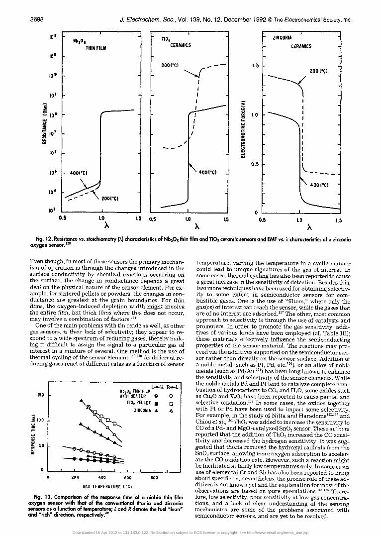
Semiconducting CoO, 13~ CoO-MgO, 136 SrTiO3 (doped with A1203, Cr203, or MgO) ~37 have also been proposed as lean-burn oxygen sensors. Another potential material un- der study for A/F control is Nb205. ~3~ Semiconducting Nb20~ thin film sensors appear to possess lower tempera- ture dependence (Fig. 12) and faster response (Fig. 13) than the other two well-established oxygen sensors (ZrO2 and TiO2), and are promising for future applications over wide range of A/F ratios and in thin film planar configuration.
As seen from Table III and the foregoing discussions, the choice of semiconducting materials for gas sensors heavily rests with those of n-type rather than p-type. This is so because, the initial adsorption of oxygen on an n-type ma- terial leads to high resistance and its removal by the reduc- ing gas, lowers the resistance. This is the preferred direc- tion for sensing reducing gases. Many p-type oxides, on the other hand, are relatively unstable because of the tendency to exchange lattice oxygen easily with the air. In the case of an n-type semiconductor, such as SnO2, the chemistry oc- curring on the surface involves two main reactions. In the first reaction, atmospheric oxygen becomes chemisorbed to the surface, consuming the electron
O2 + 2e- --) 2 O~d~ [26]
This ionosorption of oxygen results in a decrease in con- ductivity whose effect is the largest at the constricted con- tacts between the grains of a sintered powder (grain boundaries). Equation 26 is, in fact, an oversimplified pic- ture of the surface reaction, since it may also proceed via O~ or 02-; the doubly charged oxygen ion is in general ex- cluded for adsorbed species, because such a high charge on the ion may lead to instability, unless the site has a high Madelung potential. In view of normally high reactivity of O-, relative to O 2~, the latter is not expected to react significantly with the reducing gas and at moderate tem- peratures, may desorb or transform to O-. ~39.,40 The reduc- ing gas present in the ambient produces a counter reaction
R + Oad~ ---> ROd~ + e- [27]
where, the reducing gas removes the chemisorbed oxygen, frees up an electronic carrier, and increases the conductiv- ity of the semiconducting gas sensor. These two irreversible reactions, act in opposite directions and for a given concen- tration of the reducing gas, would reach a steady state.
Similar is the case with ZnO, which is also an n-type semiconductor and in which the carriers are believed to be
A
W
<
o
I.- i1. p-
0 r," 0 co Z ILl CO
1.0
0.5
i I /
J
j . t
! I I I I 0.98 I 1.02
AIR/FUEl_ RATIO (x)
- IM
<
lOOK I - U. 0 UJ o
10K ~
I.U 11:
IK
Fig. 11. Dependence of Ti02 sensor signal on the air-to-fuel ratio. '33
due to excess zinc atoms at the interstit ial positions, acting as electron donors. ~4' They are formed according to the equilibrium
ZnO ~ Zn~ + 1/2 O2 [28]
These interstitial zinc atoms are ionized via the following dissociation equilibria
Zn~ ~ Zn~ + e- [29]
and
Zn~ ~ Zn~" + e- [30]
However, studies have shown that the contribution from Eq. 30 is very small and, hence, could be neglected. More- over, zinc is not the only species which is responsible for conduction; adsorbed oxygen is a dominant contributor to the negatively charged surface states, leading to high re- sistance in ZnO in accordance with the reaction repre- sented by Eq. 26. The effect of hydrogen and oxygen chemisorption, on the electrical conductivity of ZnO has been extensively studied in the literature. 142-14s It has been shown that the chemisorption properties and the resistivity characteristics of ZnO are very sensitive functions of the type of sample (pellet or powder) and kind of pretreatment given to the oxide. The resistivity values even at room tem- peratures are different within a batch of samples, prepared under identical conditions. Moreover, the temperature- programmed desorption and other measurements show that the O~ad~ to O;ds conversion occurs at about 473 K, O ~ desorption at 523 K, and the lattice oxygen may be removed at a slightly higher temperature under vacuum. 145 Another problem is the hydrogen diffusion, since the bulk diffusion of hydrogen in ZnO might cause slow (and sometimes irre- versible) changes in bulk resistivity.
Titania becomes semiconducting when at high ~empera- tures Ti 4+ and Ti ~+ ions coexist in the lattice 146
Ti 4* ~ Ti 3§ + e- [31]
Downloaded 16 Apr 2012 to 131.183.0.122. Redistribution subject to ECS license or copyright; see http://www.ecsdl.org/terms_use.jsp
3698 J. Electrochem. Soc., Vol. 139, No. 12, December 1992 �9 The Electrochemical Society, Inc.
i012
tO it
I0 m
IO s
I0 '
i0 T M~
I0 s
IO t
I04
I0 z
I
NbzOz THIN FILM
400('C)
I TIO t
CERAMICS
200 I'C)
I
I I I I
I I
I
~" 4oo('c)
w
1.0
0 X o
0.5
I ZIRCONIA
CERAMICS
?00 I'C)
%" 400l'C}
I 0 I O.S 1.0 1.5 0,5 1.0 1.5 0,$ 1.0 1.5
k k k Fi 9. 12. Resistance vs. staichiometry (X) characteristics of Nb205 thin film and Ti02 ceramic sensors and EMF vs. ~. characteristics of a zirconia
oxygen sensor, TM
Even though, in most of these sensors the primary mechan- ism of operation is through the changes introduced in the surface conductivity by chemical reactions occurring on the surface, the change in conductance depends a great deal on the physical nature of the sensor element. For ex- ample, for sintered pellets or powders, the changes in con- ductance are greatest at the grain boundaries. For thin films, the oxygen-induced depletion width might involve the entire film, but thick films where this does not occur, may involve a combination of factors. 147
One of the main problems with tin oxide as well, as other gas sensors, is their lack of selectivity; they appear to re- spond to a wide spectrum of reducing gases, thereby mak- ing it difficult to assign the signal to a part icular gas of interest in a mixture of several. One method is the use of thermal cycling of the sensor element./48'I49 As different re- ducing gases react at different rates as a function of sensor
150
ez I00
o= 50
L'~R R-~L Nl0eO s THIN FILM WITH HEATER �9 0
TIO z PELLET i Q ZIRCONIA �9 A
e t I I I I I I I
2 0 0 4 0 0 6 0 0 8 0 0
GAS T E M P E R A T U R E ( ' C )
Fi 9. 13. Comparison of the response time of a niobia thin Film oxygen sensor with that of the conventional titania and zirconia sensors as a function of temperature; L and R denote the fuel "lean" and "rich" direction, respectively. 4v
temperature, varying the temperature in a cyclic manner could lead to unique signatures of the gas of interest. In some cases, thermal cycling has also been reported to cause a great increase in the sensitivity of detection. Besides this, two more techniques have been used for obtaining selectiv- ity to some extent in semiconductor sensors for com- bustible gases. One is the use of "filters," where only the gas(es) of interest can reach the sensor, while the gases that are of no interest are adsorbed. 127 The other, most common approach to selectivity is through the use of catalysts and promoters. In order to promote the gas sensitivity, addi- tives of various kinds have been employed (cf. Table III); these materials effectively influence the semiconducting properties of the sensor material. The reactions may pro- ceed via the additives supported on the semiconductor sen- sor rather than directly on the sensor surface. Addition of a noble metal (such as Pt, Pd, etc.15~ or an alloy of noble metals (such as Pd/Au 151) has been long known to enhance the sensitivity and selectivity of the sensor elements. While the noble metals Pd and Pt tend to catalyze complete com- bustion of hydrocarbons to CO2 and H20, some oxides such as Cu20 and V205 have been reported to cause partial and selective oxidation. 127 In some cases, the oxides together with Pt or Pd have been used to impart some selectivity. For example, in the study of Nitta and Haradome 1~2'153 and Chiou e t a l . , 134 ThO2 was added to increase the sensitivity to CO of a Pd- and MgO-catalyzed SnO2 sensor. These authors reported that the addition of ThO2 increased the CO sensi- tivity and decreased the hydrogen sensitivity. It was sug- gested that thoria removed the hydroxyl radicals from the SnO2 surface, allowing more oxygen adsorption to acceler- ate the CO oxidation rate. However, such a reaction might be facilitated at fairly low temperatures only. In some cases use of elemental Cr and Sb has also been reported to bring about specificity; nevertheless, the precise role of these ad- ditives is not known yet and the explanation for most of the observations are based on pure speculations. 155,1~6 There- fore, low selectivity, poor sensitivity at low gas concentra- tions, and a lack of clear understanding of the sensing mechanisms are some of the problems associated with semiconductor sensors, and are yet to be resolved.
Downloaded 16 Apr 2012 to 131.183.0.122. Redistribution subject to ECS license or copyright; see http://www.ecsdl.org/terms_use.jsp
J. Electrochem. Soc,, Vol. 139, No. 12, December 1992 �9 The Electrochemical Society, Inc. 3699
Yamazoe 157 has stressed the need to differentiate the re- 10000 ceptor function (to interact with the reactive gases) from i the transducer function (to transduce the effect of interac- 100o tion into signals). The receptor function is provided by the semiconductor surface and the foreign metals and/or ox- 1~ ides if present, while the transducer function largely de- pends on the microstructure of the sensing element, espe- 10 cially on the size of crystallites relative to the Debye length. Nevertheless, both these functions are strongly dependent on various factors (such as the grain size, role of metal ~" 1 sensitizer, and gas-selective sensitization, etc.), which give rise to rather complex outcomes in sensitivity and selectiv- .1 ity. Based on XPS measurements on Pd-modified SnO2 sen- sors, Yamazoe e t al . 158 have distinguished two types of .01 interactions, chemical and electronic, leading to sensitiza- tion. In chemical interaction, the additives assist the redox .0Ol processes of semiconductive oxides, whereas in electronic 0 interaction, the additives interact electronically with the semiconductor as a sort of electron acceptor or donor. This causes a change in the electronic states of the additive, which in turn causes a change in surface conductivity. Xu e t al . ~59 have studied the correlation between the gas sens- ing characteristics of SnO~-based sensors, where SnO2 grain size was controlled by the addition of several do- pants. It was found that the gas sensitivity increased with ~, / decreasing crystallite size (of the order of 5-10 nm). They ~ | interpreted the observed correlation in terms of the relative i magnitudes of the crystallite diameter (D) and the Debye "~ length (L). As D decreases and becomes closer to 2 L, the space-charge region is believed to become more dominant "~ in each crystallite of the sensing material. Thus the electric -~ resistance would become more sensitive to the reactive gases. In the case of the sensor doped with rare-earth- or ~ 10 alkaline-earth metals or with Ni and Zn (more or less stable valency), the crystallite size was about 5 nm (close to 2 L; for SnO2, reported L = 3 nm), and in these cases the gas sensitivity was found to be exceptionally high.
Substantial work has been carried out in the authors' laboratory to identify new semiconductor oxide materials, or to tune the known semiconductors by proper chemistry
0 variations for their application as CO and H2 sensors in combustion furnaces and in automobile exhaust systems at temperatures ~773 K and higher. Azad e t al.16~ have re- cently developed a new carbon monoxide gas sensor based on MoO~. It was found that the MoO3 thick films could be used as on/off type detectors, whereas those based on thin films and the two-phase mixture of ZrO2-MoO3 (1:2 molar ratio) could be employed for measuring the concentration of CO gas in the fuel-fired furnaces. Figure 14 compares the patterns of resistance change of MoO3 film with that of a two-phase binary mixture of ZrO2 and MoO 3 in the pres- ence of CO. It is evident that the binary mixture showed
1.2
_ i MoO3 0.8
o 0.6
0.4
O2
O O . O m I l I i
o 1 2 3
CO
Fig. 14. Comparison of the resistance characteristics of MoO3 and ZrO2-Mo03 (ZM2) thick films at 500~ Ro is the sample resistance in nitnxjen. 16~
i
=
- - N N
l n I I
1 2 3 4 % C O
|
M-I M-2
Fig. 15. Resistance of undoped andoPd-doped MoO3 thick films as a function of CO concentration at 500 C; M-O: pure MOO3; M- 1: with 1 w/o Pd; M-2: with 2 w/o Pd. ~6~
| i i I
i I I I I i I
O.O O.S 1.0 1.5 2.0
% Pd
Fig. 16. Response time vs. Pd content in MoO3 thick films in 0.5 v/o CO at 500~ 16~
i
.$
strikingly different behavior towards CO. In the case of sensor made from pure MoO3 (both in thick film and sin- tered pellet configurations), the resistance decreased rapidly in the presence of small concentrations of CO in the gas stream and reached a value which was several orders of magnitude lower than that before the introduction of CO in the furnace. In contrast to this, the resistance of the sensor made from the two:phase mixture of MoO3 with ZrO2, dropped monotonously and gradually with increasing CO concentration and seemed to reach saturation, for concen- trations greater than about three volume percent (v/o) of CO. Incidentally, the thin films of MoO~ deposited on zirco- nia substrate exhibited similar behavior. Such behavior, according to these authors, might suggest the possibility that zirconia, present as a second phase, plays a definite role. It is believed that zirconia might act as a "low activa- tion energy" diffusion barrier for the oncoming CO, caus- ing the resistance of the sample to drop continuously in a steady fashion. This would continue unti l saturation level in the resistance is reached for a given CO concentration. In a binary mixture such as this, the grain boundary effects, however, cannot be ruled out. Moreover, there is a possibil- ity that in the case of thin films of MoO3 on zirconia sub- strate, the film might actually consist of a two-phase mix- ture of ultrafine thinness, rather than of pure MoO~ on an inert substrate.
The sensitivity and response time of MoO3-based sensors were greatly improved by the addition of small amounts of palladium, as shown in Fig. 15 and 16. Typically, a 2 w/o
Downloaded 16 Apr 2012 to 131.183.0.122. Redistribution subject to ECS license or copyright; see http://www.ecsdl.org/terms_use.jsp
3700 J. Electrochem. Soc., Vol. 139, No. 12, December 1992 �9 The Electrochemical Society, Inc.
Oxygen
@ Interstitial Oxygen
b
vacancy
Oxygen
Fig. 17. Hypothetical defect structure of (a) the sensor surface and (b) the reduced surface? 6~
rather than Eq. 34. At the saturation level, an almost com- plete consumption of O;' species on the surface has been postulated and a hypothetical schematic of the reduced surface (MOO3_=, x -< 1; in this case x = 1) is shown in Fig. 17b.
Turning on air or oxygen at this juncture is likely to anneal the oxygen vacancies on the surface, regenerating the original surface. The reoxidation of the oxide lattice may be represented by Eq. 35a-d
O2 + e- ---> O~,~d~ [35a]
O~,~d~ + e --) O~a~ [35b]
0~:-~,t~ --> 20~d~ [35c]
O~d~ + Vb + e ---> Oo [35d]
Madou and Morrison 127 have also suggested a similar scheme.
The enhanced sensitivity of the Pd-doped MoO3 sensor was explained by the above mentioned scheme, with the recognizance that Pd plays a role of catalyst in the MoO3 matr ix and promotes the sensitivity by providing adsorp- tion sites to the oncoming CO gas, which then reacts with the M o Q surface. The following sequence of reactions have been postulated in the presence of Pd
CO (g) ---> CO~a~(Pd) + e- [36]
CO~ds(Pd ) + O/'(MoQ) --> COO;d~ [37]
o r
CO~d~(Pd) + Oo(MoO3) --+ COQd~ + Vo [38]
Pd-doped MoO3 film took 3 min, compared to 17 min taken by an undoped film, when 0.5 v/o of CO gas was introduced. The XPS analyses of the thick as well as thin film samples of MoO3 sensor elements after their exposure to CO gas were found to unequivocally establish that the redox pro- cesses involved were primarily surface dominated. On the basis of these experimental evidences, a sensing mechan- ism, operative in MoO3-based sensors has been postu- lated, ~6~ where the chemical reaction of CO with the lattice oxygen is the predominant factor in governing the resis- tance change of the sensor. As pointed out earlier, in the gas sensor technology, it is generally accepted that the chemisorption or ionosorption of "nucleophilic" O ~- ions on the surface of an n-type semiconductor creates a thin layer of high electric resistance. When these chemisorbed or ionosorbed oxygen species are consumed by a reducing gas, the net result is an accumulation of free electrons, which is manifested in the form of increase in conductivity. Oxygen, however, cannot be chemisorbed on undoped stoi- chiometric n-type oxides. On the other hand, from thermo- dynamic considerations, a defect structure consisting of bulk oxygen vacancies and interstitial oxygen ions acting as donor species is always present. This allows for either (i) the adsorption of a small fraction of a monolayer of oxygen ions, 161 or (i/) the formation of additional donors near the surface. Based on the experimental evidence, Azad et al. concluded that the latter might be the case with MoO~- based sensors. A schematic of the defect surface of the sen- sor is shown in Fig. 17a, for which the following defect equilibrium could be writ ten in terms of the KrSger-Vink notations
Oo ~ 0;% Vb [32]
And the reaction of CO with the surface might occur as
CO (g) + O(" ~ CO2 (g) + 2e- [33]
o r
CO (g) + Oo ~ CO2 (g) + V5 + 2e- [34]
where the defect symbols have their usual universal significance.
It was concluded that the experimental results were in better conformity with the reaction of CO as per Eq. 33
COOad~ ---> CO2(g) + e- [39]
The formation of adsorbed carboxylate ion on several ox- ides has been reported in the literature. 182
Birkefeld et al. 163 and Akbar et al. 164 have investigated TiO~-based semiconducting oxides as a potential sensor material for reliable detection of CO and H2 gas in the tem- perature range of 773 to 1073 K. They report significant change in the sensing characteristics of the anatase modification of TiO2 when it was admixed with an insulat- ing second phase such as a-a lumina or yttria. In the case of alumina dispersion in the TiOz matrix, the sensor response was found to be exclusively dependent on the hydrogen concentration alone in the gas phase; the presence of CO or CO~ did not affect the sensitivity (Fig. 18). On the other hand, the sensitivity for both CO and H2 was enhanced when yttria was used as the dispersoid (Fig. 19). Creation of a space-charge region at the interface, the nature of which solely depended on the type of the second phase, is believed to be responsible for the observed beneficial effects.
~ ~ <.__ 1 .001
o; ; j j ,0 12 % gas
Fi 9. 18. Response of a 10 w/o A]203 doped-Ti02 sensor to CO, C02, and H2 ot 500~ '63''~
Downloaded 16 Apr 2012 to 131.183.0.122. Redistribution subject to ECS license or copyright; see http://www.ecsdl.org/terms_use.jsp
J. Electrochem. Soc., Vol. 139, No. 12, December 1992 �9 The Electrochemical Society, Inc. 3701
10
.01
.001
. 0001
�9 CO 1 [ ---e---CO t
' ' ' ' ' ' ' ' ' ( 2
i I | i , | I , I ,
2 4 6 8 10 12
Fig. 19. Response of a 10 w/o Y203 cloped-Ti02 sensor to CO and H7 at 500~ inset: response of pure Ti02 at 500~ '~''~
Several preliminary research works have been reported in the literature to develop NO= sensors based on semicon- ducting oxides 165'167 and an In3+-doped TiO2 sensor has been commercialized. However, these sensors are poor to modest in their sensitivity to either NO or NO2. Recently, Akiyama et al. 168 have identified tungsten oxide (WO3) as a highly sensitive material for NO (0-200 ppm) and NO2 (0-800 ppm) in the temperature range of 473 to 773 K.
There has been relatively much less work on humidity sensors, based on semiconductor principles, where the hu- midity could be measured by the increase in conductivity due to the "donor-like" behavior of adsorbed water on semiconductors. However, from a chemical point of view, H20 is much too stable a molecule to inject electrons into the valence or conduction band of most of the semiconduc- tors. Morrison 169 has suggested that the electron injection is not from the water molecule but from the adsorbed oxygen ions. The polar water molecule, adsorbing adjacent to oxy- gen ions changes the energy level and the rate of electron injection and extraction of the latter, resulting in a net loss in the density of adsorbed negatively charged oxygen ions. Such a highly hypothetical model may or may not be valid but derives some support from indirect experimental evi- dence, where the response of semiconductor sensors for other gases is found to be somewhat modified in the pres- ence of moisture.
Semiconductor-based sensors for CO2 are like humidity sensors in the sense that CO2 also happens to be chemically stable compound and has little tendency to inject or extract electrons from a semiconductor. From this point of view, semiconductor sensors for CO2 are not so common. On the other hand, CO2 has a tendency to adsorb on oxides with local bonding, making a carbonate-like structure, that may change the intergranular conductance (by changing the conduction band edge, for example) or may change the ad- sorption site for oxygen. Either of these possibilities could indirectly change the conductance of a pressed semicon- ductor pellet and thus make it CO2 sensitive. A change in capacitance can be used for CO2 detection, since the dielec- tric constant of oxides generally differ from that of carbon- ates. Based on these concepts, u et al. ~7o have re- ported the CO2 sensing capability of metal oxide-modified SnO~ element. Among the various metal oxide dopants used (as many as 16 different oxides were investigated), those based on R203 (R = La, Pr, and Nd) were found to be the most efficient in terms of sensitivity and the 90% response time. Recently, Ishihara et al. ]~1.172 have demonstrated the potentials of NiO-, CuO-, and PbO-BaTiO3 and CuO- BaSnO3 mixed capacitors as selective carbon dioxide sen- sors over a wide range of concentrations (_<50%) and tem- peratures (400-800 K). However, the application of these sensors is limited to the oxidative environment, since some of the transit ion metal oxides mixed with BaTiO3 or
BaSnO3 (e.g., CuO or NiO) might get reduced to lower ox- ides (Cu20) or the respective metal. Ishihara et al. also pro- posed a three-step detection mechanism, operative in these sensors: adsorption of COs, carbonation of the second- phase oxide, and the joint grain effect. These workers have also emphasized that the capacitance changes of the sensor element were caused mainly by the carbonation of the ox- ides, since the optimum operating temperatures of CO2 de- tection showed a good correlation with the decomposition temperature of the carbonate corresponding to the metal oxide. However, much work needs to be done in this area, since CO2 sensing is an important aspect of environmental safety from the viewpoint of global warming.
Summary Gas sensors can be broadly categorized as semiconductor
sensors, catalytic combustion sensors, and solid electrolyte sensors. A variety of sensors responsive to gases such as CO, CO2, 02, H2, NO=, CH4, C3H8, C2H5OH have been developed. These ceramic sensors are easy to use and offer viable alter- natives to several conventional techniques such as gas chromatography and infrared absorption, and they can also be used for hazardous gas alarms and leakage detec- tors. Sensors measuring the equilibrium as well as the true oxygen concentrations, detectors able to measure the CO to 02 ratio, which is a measure of the degree of combustion, are also available. Although extensive advances have been made.in the sensor technology, problems such as poor se- lectivity with respect to the interference of ambient gases, a lack of understanding of the sensing mechanisms, and aging have to be overcome before reliable instrumentation can be designed. Further research in this area should lead to the development of reliable sensor systems, which when used with the available electronics and software, are antic- ipated to aid greatly in the design of intelligent industrial processes with efficient emission control.
Acknowledgments This work was partially supported by The Edison Mate-
rials Technology Center (EMTEC) of Ohio, with matching funds from The Edward Orton Jr. Ceramic Foundation, Westerville, Ohio.
Manuscript submitted March 13, 1992; revised manu- script received July 7, 1992.
REFERENCES 1. N. Taguchi, U.S. Pat. 3,631,436 (1971). 2. J. Watson and D. Tanner, Radio Electron. Eng., 44, 85
(1974). 3. J. Fouletier, P. Farby, and M. Kleitz, This Journal,
123, 204 (1976). 4. T. Oyabu, J. Appl. Phys., 53, 2785 (1985). 5. S. R. 1V~orrison, Sensors Actuators, 12, 425 (1987). 6. A. K. Guha, S. K. Mukherjee, and S. K. Banerjee,
Trans. Ind. Ceram. Soc., 49, 38 (1990). 7. O. Kubaschewski and C. B. Alcock, Metallurgical
Thermochemistry, 6th ed., Pergamon Press, London (1983).
8. G. P. Demopoulos and V. G. Papangelakis, CIM Bull., 82, 85 (1989).
9. K. Nyavor and N. O. Egiebor, J. Metals, 43, 32 (1991). 10. C.W. Seigmund and D. W. Turner, Trans. ASME, 96A,
1 (1974). 11. Z. R. Ismagilov and M. A. Kerzhentsev, Catal. Rev.-
Sci. Engg., 32, 51 (1990). 12. S. H. Schneider, Sci. Amer., 256, 78 (1987). 13. S. H. Schneider, ibid., 261, 70 (1989). 14. J. A. Laurman, in Carbon Dioxide and Other Green-
house Gases: Climatic and Associated Impact, R. Fantechi and A. Ghazi, Editors, p. 101, Kluwer Aca- demic Press, Boston, MA (1989).
15. R. M. White, Sci. Amer., 263, 37 (1990). 16. A. Berger, in Carbon Dioxide and Other Greenhouse
Gases: Climatic and Associated Impacts, R. Fan- techi and A. Ghazi, Editors, p. 135, Kluwer Aca- demic Press, Boston, MA (1989).
17. J. F. B. Mitchell, ibid., p. 144. 18. W. Gajewski, Ceram. Forum Int./Ber. DKG, 68, 33
(1991).
Downloaded 16 Apr 2012 to 131.183.0.122. Redistribution subject to ECS license or copyright; see http://www.ecsdl.org/terms_use.jsp
3702 J. Electrochem. Soc., Vol. 139, No. 12, December 1992 �9 The Electrochemical Society, Inc.
19. K. Kampfer, E. Prescher, and H.-H. Mobius, ibid., 68, 126 (1991).
20. H. Jacobs, W. Mokwa, D. Kohl, and G. Heiland, Vac- uum, 33, 869 (1983).
21. W. Thoren, Ph.D. Thesis, Aachen, Germany (1983). 22. G. Heiland and D. Kohl, in Chemical Sensor Technol-
ogy, Vol. 1, T. Seiyama, Editor, p. 15, Kodansha Ltd., Tokyo (1988).
23. T. Nitta, F. Fukushima, and Y. Matsuo, in Proceedings of International Meeting on Chemical Sensors, p. 387, Fukuoka, Japan (1983).
24. T. Nitta, in Chemical Sensor Technology, Vol. 1, T. Seiyama, Editor, p. 37, Kodansha Ltd., Tokyo (1988).
25. Practical Handbook of Chemical Sensors, T. Seiyama, Editor, Fuji Technosystem, Tokyo (1986).
26. A. Ikegami and M. Kaneyasu, Digest of Technical Pa- pers, "Transducers '85," p. 136 (1985).
27. M.W. Seigle, L. Wong, R. J. Lauf, and B. S. Holfheins, Digest of Technical Papers, "Transducers '87," p. 599 (1987).
28. J. Watson, Sensors Actuators, 5, 29 (1984). 29. A. R. Barker and J. G. Firth, Mining Eng., 128, 237
(1969). 30. G. Adachi and N. Tmanaka, in Chemical Sensor Tech-
nology, Vol. 3, N. Yamazoe, Editor, p. 131, Kodan- sha Ltd., Tokyo (1991).
31. K. S. Goto, Solid State Electrochemistry and Its Ap- plication to Sensors and Galvanic Devices, Elsevier Pub. Co., Amsterdam (1988).
32. R. Sladek, Ceram. Forum. Int./Ber. DKG, 66, 220 (1989).
33. G. Fisher, Am. Ceram. Soc. Bull., 65, 622 (1986). 34. S. Annon, Adv. Ceram. Rep., 3, 1 (1988). 35. R. V. Wilhem, Jr., and D. S. Eddy, Am. Ceram. Soc.
Bull., 56, 509 (1977). 36. E. M. Logothetis, in Advances in Ceramics, VoL 3,
Science and Technology of Zirconia /, A. H. Heuer and L. W. Hobbs, Editors, p. 388, The American Ce- ramic Society, Columbus, OH (1981).
37. T. Usui, A. Asada, M. Nakazawa, and I-I. Osanai, This Journal, 136, 537 (1989).
38. C. T. Young and 5. D. Bode, Paper No. 790,143, pre- sented at the Society of Automotive Engineers Con- gress, Detroit, MI, 1979.
39. W. J. Flemings, Paper No. 800,020, presented at the Society of Automotive Engineers Congress, Detroit, MI, 1980.
40. W. Weppner and H. Schubert, in Advances in Ceram- ics, Vol. 24, Science and Technology of Zirconia III, S. Somiya, Editor, p. 837, The American Ceramic Society, Columbus, OH (1988).
41. T. Sato, M. Ishitsuka, T. Fukushima, T. Endo, and M. Schimada, Mater. Sci. Forum, 34-36, 189 (1988).
42. B. Y. Liaw and W. Weppner, This Journal, 138, 2478 (1991).
43. H. Dietz, Solid State Ionics, 6, 175 (1982). 44. M. Nakazawa, H. Osanai, Y. Isono, A. Asada, and H.
Ohira, U.S. Pat. 4,571,285 (1986). 45. H. Jahnke, B. Moro, H. Dietz, and B. Beyer, Ber. Bun-
senges. Phys. Chem., 92, 1250 (1988). 46. K. Sail, H. Takahashi , H. Kondo, T. Takeuchi, and I.
Igarashi, in Proceedings of 4th Sensor Symposium, p. 147, Tsukuba, Japan (1984).
47. T. Kamo, Y. Chujo, T. Akatsuka, T. Nakamo, and M. Suzuki, Paper 850, 380 presented at Society of Au- tomotive Engineers Congress, Detroit, MI, 1985.
48. H. Kondo, H. Takahashi, K. Saji, T. Takeuchi, and I. Igarashi, in Proceedings of 6th Sensor Symposium, p. 251, Tsukuba, Japan (1986).
49. T. Takeuchi, Sensors Actuators, 14, 109 (1988). 50. T. Usui, A. Asada, M. Nakazawa, and H. Osanai, Jpn.
J. Appl. Phys., 28, L1654 (1989). 51. T. Usui, A. Asada, K. Ishibashi, and M. Nakazawa,
ibid., 28, 2046 (1989). 52. T. Usui and A. Asada, in Advances in Ceramics, Vol.
24, Science and Technology of Zirconia III, S. Somiya, Editor, p. 845, The American Ceramic Soci- ety, Columbus, OH (1988).
53. M. Maeda and S. Nagao, Yokogawa Electric Co., Japan, Private communication.
54. H. Iwahara, T. Esaka, H. Uchida, and N. Maeda, Solid State Ionics, 3/4, 359 (1981).
55. H. Iwahara, H. Uchida, K. Kondo, and K. Ogaki, This Journal, 135, 529 (1989).
56. H. Iwahara, H. Uchida, K. Ogaki, and H. Nagato, ibid., 138, 295 (1991).
57. H. Uchida, N. Maeda, and H. Iwahara, Solid State Ionics, 11, 117 (1983).
58. H. Iwahara, in Chemical Sensor Technology, Vol. 3, N. Yamazoe, Editor, p. 117, Kodansha Ltd., Tokyo (1991).
59. S. Stotz and C. Wagner, Ber. Bunsenges. Phys. Chem., 70, 781 (1980).
60. D. A. Shore and R. A. Rapp, This Journal, 119, 300 (1972).
61. T. Takahashi and H. Iwahara, Rev. Chim. Miner., 17, 243 (1980).
62. T. Norby and P. Kofstadt, J. Am. Ceram. Soc., 69, 784 (1986).
63. L. Wing-Kit and A. S. Nowick, Solid State Ionics, 18/ 19, 989 (1986).
64. T. M. Gur and R. A. Huggins, This Journal, 126, 1067 (1979).
65. H. Schmalzried, Arch. Eisenhuttw, 48, 319 (1977). 66. K. Nagata and K. S. Goto, in Metallurgische Elec-
trochimie, W. A. Fischer and D. Janke, Editors, Springer-Verlag, Amsterdam (1975).
67. W. A. Fischer and D. Janke, ibid. 68. K. Ono, T. Oishi, and J. Moriyama, Solid State Ionics,
3/4, 555 (1981). 69. A. Egami, T. Onoye, and K. Narita, ibid., 3/4, 617
(1981). 70. K. T. Jacob, M. Iwase, and Y. Waseda, J. Appl. Elec-
trochem., 12, 55 (1982). 71. M. Itoh and Z. Kozuka, Trans. Jpn. Inst. Metals, 26, 17
(1985). 72. M. Itoh, K. Kimura, S. Iijima, and Z. Kozuka, Met.
Rev. MMIS, 3, 5 (1986). 73. Y. Saito, T. Maruyama, Y. Matsumoto, and Y. Yano, in
Proceedings of the International Meeting on Chemi- cal Sensors, Vol. 17, p. 326, ACS Series, Elsevier (1983).
74. Y. Saito, T. Maruyama, Y. Matsumoto, K. Kobayashi, and Y. Yano, Solid State Ionics, 14, 273 (1985).
75. T. Maruyama, Y. Saito, Y. Matsumoto, and Y. Yano, ibid., 17, 281 (1985).
76. W. L. Worrell, in Proceedings of International Meet- ing on Chemical Sensors, p. 332, Fukuoka, Japan (1983).
77. W. L. Worrell and Q. G. Liu, J. Electroanal. Chem., Interfac. Electrochem., 168, 355 (1984).
78. Q. G. Liu and W. L. Worrell, Solid State Ionics, 28-30, 1668 (1988).
79. W. L. Worrell, in Chemical Sensor Technology, Vol. 1, T. Seiyama, Editor, p. 97, Kodansha Ltd., Tokyo (1988).
80. M. Gauthier and A. Chamberland, This Journal, 124, 1579 (1977).
81. M. Gauthier, A. Chamberland, A. Belanger, and M. Poirier, ibid., 124, 1584 (1977).
82. M. Gauthier, R. Bellemare, A. Belanger, and M. Poirier, ibid., 128, 371 (1981).
83. M. Gauthier and C. W. Bale, Metall. Trans. B, 14B, 117 (1983).
84. K. T. Jacob and D. B. Rao, This Journal, 126, 1842 (1979).
85. N. Imanaka, G. Adachi, and J. Shiokawa, Chem. Lett., 287 (1983).
86. N. Imanaka, G. Adachi, and J. Shiokawa, Denki Ka- gaku, 51, 193 (1983).
87. N. Imanaka, G. Adachi, and J. Shiokawa, Bull. Chem. Soc. Jpn., 57, 687 (1984).
88. N. Imanaka, G. Adachi, and J. Shiokawa, in Proceed- ings of International Meeting on Chemical Sensors, p. 348, Fukuoka, Japan (1983).
89. N. Imanaka, G. Adachi, and J. Shiokawa, in Funda- mental and Applications of Chemical Sensors, ACS Symp. Series 309, D. Schuelzle and R. Hammerle, Editors, p. 121, ACS (1986).
90. N. Imanaka, Y. Yamaguchi, G. Adachi, J. Shiokawa, and H. Yoshioka, Solid State Ionics, 20, 153 (1986).
91. N. Imanaka, K. Kuwabara , G. Adachi, and J. Shio- kawa, ibid., 23, 15 (1987).
92. F .J . Salzano and L. Newman, This Journal, 119, 1273 (1972).
93. M. Natara jan and E. A. Secco, Can. J. Chem., 53, 1542 (1975).
94. A. Kvist and A. Lunden, Z. Naturforschg., 20a, 235 (1965).
Downloaded 16 Apr 2012 to 131.183.0.122. Redistribution subject to ECS license or copyright; see http://www.ecsdl.org/terms_use.jsp
J. Electrochem. Soc., Vol. 139, No. 12, December 1992 �9 The Electrochemical Society, Inc. 3703
95. G. Adachi and N. Imanaka, in Chemical Sensor Tech- nology, Vol. 3, N. Yamazoe, Editor, p. 131, Kodan- sha Ltd., Tokyo (1991).
96. N. Imanaka, K. Kawai, J. Shiokawa, and G. Adachi, Chem. Lett., 1133 (1988).
97. Q. G. Liu and W. L. Worrell, in Physical Chemistry of Extractive Metallurgy, V. Kuduk and Y. K. Rao, Ed- itors, p. 387, The Metallurgical Society, Warrington, PA (1985).
98. K. T. Jacob, M. Iwase, and Y. Waseda, Solid State Ionics, 23, 245 (1987).
99. R. Akila and K. T. Jacob, Sensors Actuators, 16, 311 (1989).
100. R. Akila and K. T. Jacob, J. Appl. Electrochem., 18, 245 (1988).
101. R. Cote, C. W. Bale, and M. Gauthier, This Journal, 131, 63 (1984).
102. H. Aono, E. Sugimoto, Y. Sadaoka, N. Imanaka, and G. Adachi, ibid., 136, 590 (1989).
103. H. Aono, E. Sugimoto, Y. Sadaoka, N. Imanaka, and G. Adachi, ibid., 137, 1023 (1989).
104. N. Imanaka, T. Kawasato, and G. Adachi, Chem. Lett., 497 (1990).
105. N. Imanaka, T. Kawasato, and G. Adachi, ibid., 13 (1991).
106. T. Maruyama, S. Sasaki, and Y. Saito, Solid State Ion- ics, 23, 107 (1987).
107. Y. Saito and T. Maruyama, ibid., 28-30, 1664 (1988). 108. S. Yao, S. Hosohara, Y. Shimizu, N. Miura, H. Futata,
and N. Yamazoe, Chem. Lett., 2069 (1991). 109. T. Arakawa, S. Takeda, G. Adachi, and J. Shiokawa,
Mater. Res. Bull., 14, 507 (1979). 110. K. Angata and H. Futata , in Proceedings of Interna-
tional Meeting on Chemical Sensors, p. 208, Fukuoka, Japan (1983).
111. N. Ichinose, Am. Ceram. Soc. Bull., 64, 1581 (1985). 112. H. Obayashi, Y. Sakurai , and T. Gejo, J. Solid State
Chem., 17, 299 (1976). 113. T. Arakawa, A. Yoshida, and J. Shiokawa, Mater. Res.
Bull., 15, 269 (1980). 114. T. Arakawa, A. Yoshida, and J. Shiokawa, ibid., 15,
347 (1980). 115. T. Arakawa, S. Tsuchi-ya, and J. Shiokawa, ibid., 16,
97 (1981). 116. T. Arakawa, S. Tsuchi-ya, and J. Shiokawa, J. Catal.,
74, 317 (1982). 117. T. Arakawa, N. Ohara, H. Kurachi, and J. Shiokawa,
in Proceedings of International Meeting on Chemi- cal Sensors, p. 159, Fukuoka, Japan (1983).
118. N. Gunasekaran, A. Meenakshisundaram, and V. Srinivasan, Surf. Technol., 22, 89 (1984).
119. B. de Collongue, E. Garbowski, and M. Primet, J. Chem. Soc. Faraday Trans., 87, 2493 (1991).
120. J. Bardeen, Phys. Rev., 71, 717 (1947). 121. S. W. Weller and S. E. Voltz, Adv. Catal., 9, 215 (1957). 122. J. J. Brophy and J. W. Battrey, Organic Semiconduc-
tors, MacMillan, New York (1963). 123. J. R. Stetter, J. Colloid Interf. Sci., 65, 432 (1978). 124. E. C. M. Hermans, Sensors Actuators, 5, 181 (1984). 125. H. Wohltjen, W. R. Barger, A. W. Snow, and N. L.
Jarvis, IEEE Trans. Electron Device, ED-32, 1170 (1985).
126. H. Pink, L. Trietinger, and L. Vite, Jpn. J. Appl. Phys., 19, 513 (1980).
127. M. J. Madou and S. R. Morrison, Chemical Sensing with Solid State Devices, Academic Press, Inc., New York (1989).
128. T. Seiyama, A. Kato, K. Fujiishi, and M. Nagatami, Anal. Chem., 34, 1502 (1962).
129. P. J. Shaver, Appl. Phys. Lett., 11, 255 (1967). 130. T. Oyabu, T. Kurobe, and T. Hidai, in Proceedings of
International Meeting on Chemical Sensors, T. Seiyama, Editor, p. 12, Elsevier Publishing Co., Am- sterdam (1983).
131. T. Y. Tien, H. L. Stadler, E. F. Gibbons, and P. J. Zacmanidis, Am. Ceram. Soc. Bull., 54, 280 (1975).
132. A. L. Micheli, ibid., 63, 694 (1984). 133. A. Takami, ibid., 67, 1956 (1988). 134. D. S. Howarth and A. L. Micheli, Paper No. 840,142,
presented at Society of Automotive Engineers Con- gress, Detroit, MI (1934).
135. E. M. Logothetis, K. Park, H. A. Meitzler, and K. R. Laud, Appl. Phys. Lett., 26, 209 (1975).
136. K. Park and E. M. Logothetis, This Journal, 124, 1443 (1977).
137. H. Arai and Y. Shimizu, in Chemical Sensor Technol- ogy, Vol. 2, T. Sieyama, Editor, p. 83, Kodansha Ltd., Tokyo (1989).
138. T. Takeuchi, in Proceedings of 2nd International Meeting on Chemical Sensors, p. 69, Bordeaux, France (1986).
139. H. Windischmann and P. Mark, This Journal, 126, 627 (1979).
140. P. Mark, J. Chem. Phys. Solids, 29, 689 (1968). 141. F. Caillaud, A. Smith, and J. Baumard, J. Europ. Ce-
ram. Soc., 7, 379 (1991). 142. G. Heiland, Z. Phys., 148, 15 (1957). 143. D. Narayana, V. S. Subrahmanyam, J. Lal, M. All, and
V. Kesavulu, J. Phys. Chem., 74, 779 (1970). 144. S. Saito, M. Miyayama, K. Koumoto, and H. Yana-
gida, ,1. Am. Ceram. Soc.,. 68, 40 (1985). 145. W. Hirschwald, Current Topics in Materials Science,
Vol. 7, p. 351, North-Holland, Amsterdam (1981). 146. E. M. Logothetis, in Chemical Sensors, D. R. Turner,
Editor, PV 87-9, p. 142, The Electrochemical Society Softbound Proceedings Series, Pennington, NJ (1987).
147. G. Heiland, Sensors Actuators, 2, 343 (1982). 148. W. M. Sears, K. Colbow, and F. Consadori, Semicond.
Sci. Technol., 4, 351 (1989). 149. P. Romppainen, V. Lantto, and S. Leppavuori , Sen-
sors Actuators, B1, 73 (1990). 150. S. Matsushima, Y. Teraoka, N. Miura, and N. Yama-
zoe, Jpn. J. Appl. Chem., 27, 1798 (1988). 151. V. Ponec, Catal. Rev.-Sci. Engg., 11, 41 (1975). 152. M. Nit ta and Haradome, J. Electron. Mater., 8, 571
(1979). 153. M. Nit ta and Haradome, ibid., 9, 727 (1980). 154. B. Chiou, J. Li, and J. Duh, ibid., 17, 485 (1988). 155. Y. Okayama, H. Fukaya, K. Kojima, Y. Terasawa, and
T. Handa, in Proceedings of International Meeting on Chemical Sensors, p. 29, Fukuoka, Japan (1983).
156. D. Koh], Sensors Actuators, B1, 158 (1990). t57. N. Yamazoe, Chem. Lett., 3 (1990). 158. N. Yamazoe, Y. Kurokawa, and T. Sieyama, Sensors
Actuators, 4, 283 (1983). 159. C. Xu, J. Tamaki, N. Miura, and N. Yamazoe, Chem.
Lett., 441 (1990). 160. A. M. Azad, S. G. Mhaisalkar, L. D. Birkefeld, S. A.
Akbar, and K. S. Goto, This Journal, 139, 2913 (1992).
161. G. C. Bond, Heterogeneous Catalysis: Principles and Applications, Oxford Chemistry Series, Clarendon Press, Oxford (1987).
162. M. P. Van Dijk, J. H. H. ter Maat, G. Roelofs, H. Bosch, G. M. H. van de Velde, P. G. Gellings, and A. J. Burggraaf, Mater. Res. Bull., 19, 1271 (1984).
163. L. D. Birkefeld, A. M Azad, and S. A. Akbar, J. Am. Ceram. Soc., 75, 2964 (1992).
164. S. A. Akbar, A. M. Azad, and L. D. Birkefeld, Inven- tion disclosure filed with The Ohio State University (1992).
165. T. Inoue, K. Satake, A. Kobayashi, H. Ohkoshi, T. Nakahara, and T. Takeuchi, in Digest of 12th Chem- ical Sensor Symposium, p. 129 (1991).
166. G. Sberveglieri, S. Groppelli , P. Nelli, V. Lantto, H. Torvela, R. Romppainen, and P. Leppavouri , Sen- sors Actuators, B1, 79 (1990).
167. T. Ishihara, K. Shiokawa, K. Eguchi, and H. Arai, ibid., 19, 259 (1989).
168. M. Akiyama, J. Tamaki, N. Miura, and N. Yamazoe, Chem. Lett., 1610 (1991).
169. S. R. Morrison, The Chemical Physics of Surfaces, Plenum, New York (1977).
170. T. Yoshioka, N. Mizuno, and M. Iwamoto, Chem. Lett., 1249 (1991).
171. T. Ishihara, K. Kometani, Y. Mizuhara, and Y. Takita, ibid., 1711 (1991).
172. T. Ishibara, K. Kometani, M. Hashida, and Y. Takita, This Journal, 138, 173 (1991).
173. T. Yajima, K. Koide, K. Yamamoto, and H. Iwahara, in Proceedings of 3rd International Meeting on Chemical Sensors, p. 303, Cleveland, OH (1990).
174. C. M. IVIari, G. Terzaghi, and C. Manes, ibid., p. 281. 175. C. M. Marl and G. Terzaghi, in Proceedings of Interna-
tional Meeting on Chemical Sensors, p. 272, Fukuoka, Japan (1983).
176. T. Nakahara, K. Satake, and T. Takeuchi, in Proceed- ings of 3rd International Meeting on Chemical Sen- sors, p. 205, Cleveland, OH (1990).
177. Y. Nakamura, K. Moriya, and H. Futata , ibid., p. 180.
Downloaded 16 Apr 2012 to 131.183.0.122. Redistribution subject to ECS license or copyright; see http://www.ecsdl.org/terms_use.jsp
3704 J. Electrochem. Soc., Vol. 139, No. 12, December 1992 �9 The Electrochemical Society, Inc.
178. K. Marcinkowska, M. P. McGauley, and E. A. Symons, ibid., p. 184.
179. K. Satake, A. Kobayashi , and T. Inoue, ibid., p. 334. 180. Y. Hayakawa and A. Ono, ibid., p. 31. 181. V. Lant to and T. Rantala, ibid., p. 192. 182. S. Matsushima, N. Miura, and N. Yamazoe, Chem.
Lett., 2001 (1987). 183. Y. Matsuura, N. Murakami, and K. Ihokura, in Pro-
ceedings of International Meeting on Chemical Sen- sors, p. 24, Fukuoka, Japan (1983).
184. N. Komori, S. Sakai, and K. Komatsu, ibid., p. 57. 185. A. Harkoma, H. Torvela, P. Romppainen, and S. Lep-
pavuori, Combust. Sci. Tech., 62, 21 (1988). 186. L. A. Harris, This Journal, 127, 2657 (1980). 187. C. T. Young, in Progress in Solid Electrolytes, T. A.
Wheat, A. Ahmad, and A. K. Kuriakose, Editors, p. 549, Energy, Mines and Resources, Ottawa, ON, Canada (1983).
188. E. M. Logothetis, in Chemical Sensor Technology, Vol. 3, N. Yamazoe, Editor, p. 89, Kodansha Ltd., Tokyo (1991).
189. T. Takeuchi and I. Igarashi, in Chemical Sensor Tech- nology, Vol. 1, T. Sieyaraa, Editor, p. 79, Kodansha Ltd., Tokyo (1988).
Downloaded 16 Apr 2012 to 131.183.0.122. Redistribution subject to ECS license or copyright; see http://www.ecsdl.org/terms_use.jsp