REVISED APRIL 2011 NIGHT LITE PRO 50-60 Hz SERIES OPERATOR’S MANUAL ALLMAND BROTHERS INC. P.O. BOX 888 HOLDREGE, NE 68949 PHONE: (308) 995- 4495, 1- 800- 562- 1373 ALLMAND FAX: (308) 995– 5887 ALLMAND PARTS DEPT. FAX : (308) 995– 4883 WWW.allmand.com NIGHT LITE PRO 50-60 Hz SERIES 80025536 Not for Reproduction
Transcript
REVISED APRIL 2011
NIGHT LITE PRO
50-60 Hz SERIES
OPERATOR’S
MANUALALLMAND BROTHERS INC.
P.O. BOX 888
HOLDREGE, NE 68949
PHONE: (308) 995- 4495, 1- 800- 562- 1373
ALLMAND FAX: (308) 995– 5887
ALLMAND PARTS DEPT. FAX : (308) 995– 4883
WWW.allmand.com
NIGHT LITE PRO 50-60 Hz SERIES
80025536
Not for
Rep
roduc
tion
Not for
Rep
roduc
tion
3
5/24/2011 TABLE OF CONTENTS
3
Introduction
About this Manual…………………………………………………………….7
Safety
Safety Definitions…………………………………………………………8
Safety Precautions……………………………………………………….8
Trailering, Transporting and Lifting
Preparing the Unit for delivery or Rental………………………………13
Check list………………………………………………………………….13
Before Trailering / Transporting………………………………………...15
Shutdown - Prepare for Trailering…………………………………...16
Tower Lights - Stowage for Trailering……………………………….17
Tower Lights - Removal for Trailering (optional)…………………..18
Trailering / Towing……………………………………………………19-21
Trailer Component Identification……………………………………19
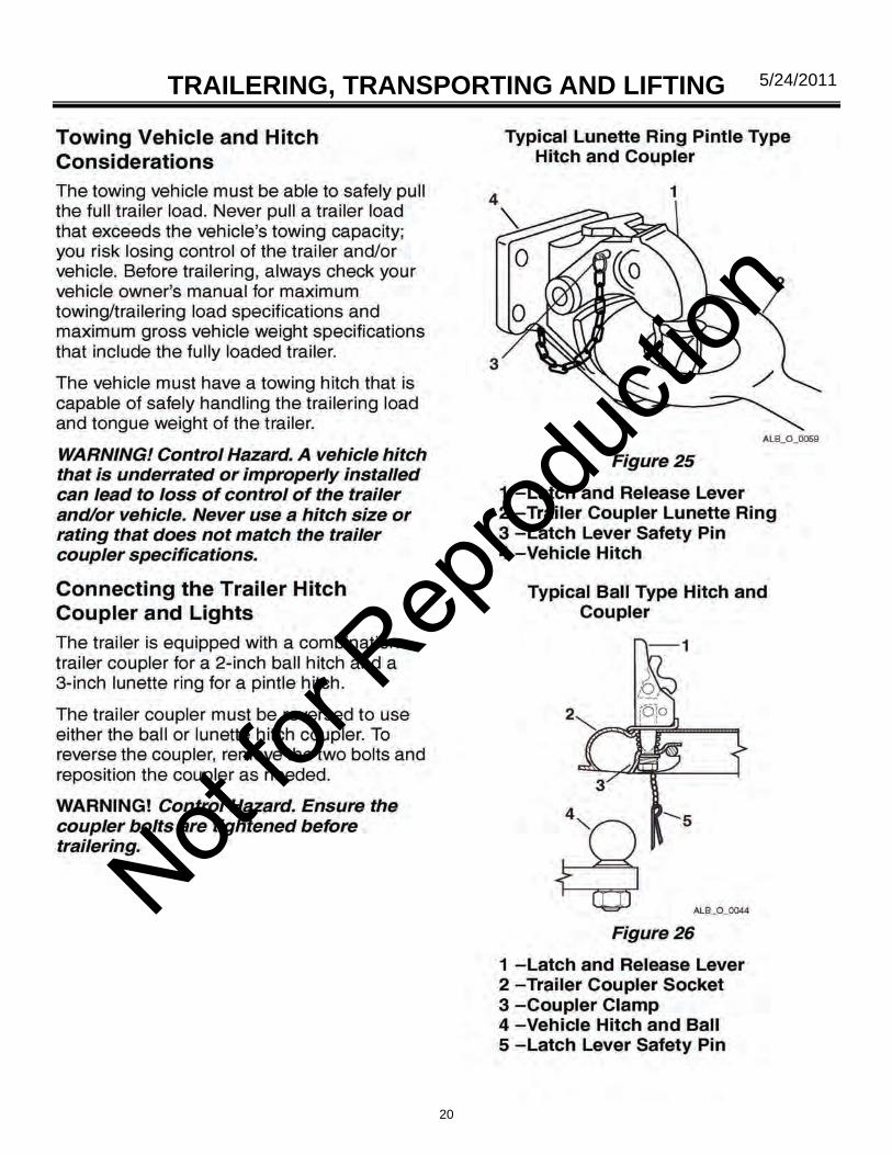
Towing Vehicle and Hitch Considerations…………………………20
Connecting the Trailer Hitch Coupler and Lights……………...20-21
Lifting the Light Tower…………………………………………………..22
Transporting on a Trailer………………………………………………..22
General Service Information
Equipment Identification………………………………………………….23
Models and Serial Numbers……………………………………………..24
Trailer…………………………………………………………………...24
Generator………………………………………………………………24
Engine……………………………………………………………….25-26
Not for
Rep
roduc
tion
4
5/24/2011 TABLE OF CONTENTS
Specifications (Standard and optional Features)……………………..27-31
Trailer…………………………………………………………………..27
Overall Dimensions…………………………………………………...28
Light Tower…………………………………………………………….28
Generator………………………………………………………………28
Tower Lights…………………………………………………………...29
Engine………………………………………………………………….30
Optional Accessory Equipment………………………………………….31
Operation
Pre - Operation Setup…………………………………………………….32
Work Site Safety Considerations…………………………………….32
Pre-Operation Check list……………………………………………...32
Leveling and Stabilizing the Trailer………………………………….33
Installing the Ground Rod…………………………………………….34
Engine Operation……………………………………………………...34-36
Pre-Start Checks……………………………………………………….34
Engine Control Panels……………………………………………..35-37
Starting the Engine…………………………………………………….38
Stopping the Engine…………………………………………………...38
Automatic Engine Shutdown System………………………………..38
Tower and Light Operation………………………………………………38
Light Bar and Light Fixture Adjustment……………………………...39
Raising and Lowering the Light Tower……………………………...39
Light Control Panel…………………………………………………….41
Not for
Rep
roduc
tion
5
5/24/2011
Shutdown Procedure……………………………………………………41
Shutdown-Short Period………………………………………………41
Shutdown Long-Term or Prepare for Trailering…………………...41
Auxiliary AC Outlet Operation………………………………………….41
Convenience Panel…………………………………………………...42
Maintenance
Engine…………………………………………………………………….43
Changing and Adding Engine Oil…………………………………...43
Engine Filters………………………………………………………….43
Electrical System………………………………………………………...43
Ballast Panel………………………………………………………43-44
Light Tower and Lamps…………………………………………………45
Changing Lamps……………………………………………………..45
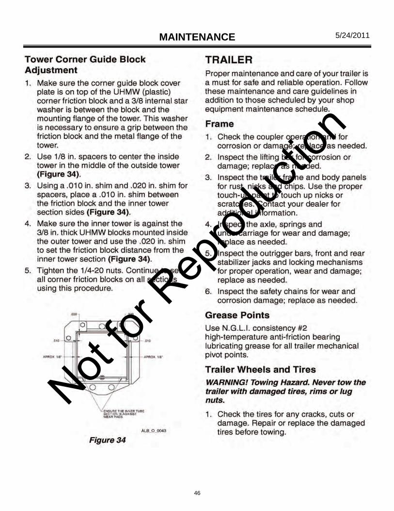
Tower corner Guide Block Adjustment…………………………….46
Trailer……………………………………………………………………..46
Frame………………………………………………………………….46
Grease Points…………………………………………………………46
Trailer Wheels And Tires………………………………………...46-47
Wheel Bearings……………………………………………………….47
Trailer Lighting…………………………………………………………48
Long-Term Storage…………………………………………………..48
Cleaning…………………………………………………………………..49
Cleaning and Draining the Trailer Bilge…………………………….49
TABLE OF CONTENTS
Not for
Rep
roduc
tion
6
5/24/2011 TABLE OF CONTENTS
Troubleshooting
Troubleshooting Chart…………………………………………………..50
Maintenance Record…………………………………………………….51
Wiring Schematics
Kohler KDW 1003 Wiring Diagram…………………………………52-53
Cat C1.1 Wiring Harness………………………………………………..54
Kubota Wiring Diagram………………………………………………55-56
SHO-HD lighting System 240V - 1000W……………………………….57
SHO-HD Lighting System 240V -1250W…………………………...58-59
Light Bar 14/7 Cord……………………………………………………….60
Tail Lamp Wiring…………………………………………………………..61
Warranty
Parts Book
Not for
Rep
roduc
tion
7
5/24/2011 INTRODUCTION
Congratulations on the purchase of your new Allmand NIGHT LITE PRO light towers and welcome to the Allmand family of equipment owners.
The Allmand NIGHT LITE PRO light towers offers many advantages to make operation safer, more convenient and more cost-effective. The NIGHT LITE PRO II light towers will provide you with high-quality performance and durability which translates into more productivity on the job site.
ABOUT THIS MANUAL
Take time to read this manual thoroughly.
This Operator’s Manual provides information necessary for the safe operation of the Allmand Bros. Inc. NIGHT LITE PRO light towers.
NOTICE: Keep this manual accessible during operation to provide convenient reference. Store this manual in a safe place for future reference.
If you are uncertain about any of the information in the manual, contact Allmand or your Allmand dealer for clarification before operation.
Specific operating instructions and specifications are contained in this publication to familiarize the operator and maintenance personnel with the correct and safe procedures necessary to maintain and operate the equipment.
Engine– specific operating instructions and specifications are contained in the engine owner’s man-ual provided in your owner’s kit. Always refer to engine owner’s manual for operation and mainte-nance procedures.
The graphics and text in this manual generally describe the Allmand NIGHT LITE PRO 50 - 60Hz light towers. Allmand light tower differ by model and optionally installed equipment. Your Allmand light tower may not exactly match the graphics and /or text descriptions in this manual.
NOTICE: The information found in this manual was in effect at the time of printing. Allmand Bros. may change contents without notice and without incurring obligation.
NOTICE: Any reference in this manual to left or right shall be determined by looking at the trailer from the rear.
Not for
Rep
roduc
tion
8
5/24/2011 SAFETY
Not for
Rep
roduc
tion
9
5/24/2011 SAFETY
Not for
Rep
roduc
tion
10
5/24/2011 SAFETY
Not for
Rep
roduc
tion
11
5/24/2011 SAFETY
Not for
Rep
roduc
tion
12
5/24/2011 SAFETY
Not for
Rep
roduc
tion
13
5/24/2011 TRAILERING, TRANSPORTING AND LIFTING
PREPARING THE NIGHT LITE PRO FOR DELIVERY OR RENTAL
The NIGHT LITE PRO light towers requires service as well as proper operation in order to provide the performance and safety it has been designed for. Never deliver or put machine into service with known defects or missing instructions or decals. Always instruct the customer in proper operation and safety procedures as described in this Operator’s Manual. Always provide the manual with the equipment for proper and safe operation.
CHECK LIST
Visually inspect the equipment to ensure that all instructions and decals are in place and legible.
Inspect the light tower locking bar latch assembly which locks the light tower in the vertical posi-tion for proper operation.
Check the hitch assembly and safety chains.
Check the outriggers and jacks to make sure they operate properly.
Inspect the light assemblies for damage and test for proper operation.
Inspect the electrical wiring for signs of damage. Danger! Electrocution Hazard.
Do not operate the light tower if the insulation on the electrical cord or other
electrical wiring is cut or worn, or if bare wires are exposed. Repair or re
place damaged wiring before starting the engine.
Check ground rod cable and the ground lug. Make sure they are clean, undamaged and func-tional.
Inspect tires to insure good condition and proper inflation.
Check engine oil, fuel, engine coolant levels and hydraulic fluid levels, if equipped.
Check to make sure the Light Tower Operator’s Manual and Generator Operator’s Manual are with the equipment.
Check to make sure the quick reference operation card is with the equipment and properly teth-ered.
Inspect the machine physically for damage and repair if necessary.
NOTICE: See appropriate section of the Engine Operator’s Manual and Generator Operator’s Manual for additional pre-operation checks.
Not for
Rep
roduc
tion
14
5/24/2011 TRAILERING, TRANSPORTING AND LIFTING After completing the pre-operation check list, operate the tower through a complete opera-tion cycle, following the operating instructions in the NIGHT LITE PRO Operator’s Manual.
Warning! Unsafe operation Hazard. Never permit anyone to install or operate the equipment without proper training.
ALWAYS READ AND UNDERSTAND THE INSTRUCTIONS FIRST.
Not for
Rep
roduc
tion
15
5/24/2011 TRAILERING, TRANSPORTING AND LIFTING
Before trailering, transporting or lifting, read Safety on page 8.
The complete engine and generator set is housed in a lockable enclosure with the frame fabricated from heavy gauge steel mounted on a two-wheel, leaf spring axle.
BEFORE TRAILERING OR TRANSPORTING
Perform the following before trailering / transporting:
Lower the light tower and shut down the tower lights and the engine; See Shutdown - prepare for trailering on page 16.
Visually inspect the trailer and equipment for damage. Repair or replace any components as needed before trailering.
Check the trailer lights for proper operation
Inspect the tires to insure good condition and proper inflation.
Inspect trailer springs and undercarriage for damage or loose parts.
Check the hitch assembly and safety chains.
Ensure the outriggers and jacks are properly stowed.
Ensure the ground rod and cable are disconnected and properly stowed.
Clean any spills from inside the trailer bilge area around the outside of the trailer; they may have occurred during operation.
Ensure all compartment doors are closed and securely locked.
Not for
Rep
roduc
tion
16
5/24/2011 TRAILERING, TRANSPORTING AND LIFTING
Shutdown - Prepare for Trailering
1. With the tower lights off, lower the light tower to the full DOWN position; See Raising and Lower-ing the light tower on page 39.
2. Turn the engine off. Refer to your Engine Operator’s Manual for stopping procedure.
Notice: See appropriate section of the Engine Operators Manual and Generator Operator’s
Manual for additional post - operation and shutdown procedures.
3. Adjust the light bar and light fixtures for trailering; see Tower lights - Stowage for trailering on
Page 17.
Notice: Visually inspect the light mounting brackets and hardware for loose fasteners or
damaged brackets. Repair any problems before trailering.
4. Secure the light cords into the hook on the rear mast support
5. Disconnect the ground rod cable from the ground lug. Remove the ground rod from the earth and
clean and secure the ground rod and cable in the trailer.
6. Close, secure and lock all compartment doors.
7. Raise each rear stabilizer jack and rotate into trailering position ( horizontal with outrigger bar).
8. Retract each outrigger bar and secure in the stowed position with latch pin.
Notice: Be sure each outrigger jack is securely latched in transporting position by installing the
outrigger lock pins before transporting.
Not for
Rep
roduc
tion
17
5/24/2011 TRAILERING, TRANSPORTING AND LIFTING Tower Lights - Stowage for Trailering
The light bar and fixtures must be stowed before trailering or transporting.
WARNING! Burn Hazard. The light fixtures become extremely hot during use.
Always use caution and heat - resistant gloves when handling the
Lights or allow to the lights to sufficiently cool down before
handling.
1. Ensure lights are off and tower is lowered to the full DOWN position; see Raising and lowering the
light Tower on page 39.
2. Release the light bar park pin by pulling the ring and turning it 90 degrees so that the pin remains
in the retracted position.
3. Rotate the light bar into the trailering / transport park position (in line with trailer) and engage the
park pin by twisting the park pin ring until the plunger is released and the pin engages and locks
into the hole in the light bar.
4. Reposition the light fixtures for trailering / transport by pulling them down into the lowest position and face the fixtures toward the center of the trailer. (see below)
NOTE: If lights are to be removed for trailering / transporting, see Tower Llghts - Removal for
trailering / transporting (Optional) on page 18.
Not for
Rep
roduc
tion
18
5/24/2011 TRAILERING, TRANSPORTING AND LIFTING
FIGURE 23
Tower Lights - Removal for Trailering (Optional)
Your light tower may be equipped with lights that can be removed for trailering / transport or for theft prevention.
WARNING! Burn Hazard. The light fixtures become extremely hot during use.
Always use caution and heat - resistant gloves when handling the
Lights or allow to the lights to sufficiently cool down before
handling.
1. Ensure lights are off and tower is lowered to the full DOWN position; see Raising and lowering the
light Tower on page 39.
2. Disconnect the electrical cord from each light fixture.
3. While supporting the light fixture, remove the nut and washer assembly fastening the main fixture
Bracket and remove each light fixture and bracket (Figure 23).
4. Store each light fixture to avoid any damage during transport.
Not for
Rep
roduc
tion
19
5/24/2011 TRAILERING, TRANSPORTING AND LIFTING TRAILERING / TOWING
Before trailering / towing the light tower trailer, read Before Trailering / Transporting on page 15 and read Safety on page 8.
NOTICE: Maximum highway speed is 50 mph (80 km/h) and maximum off highway speed is 10 mph (16 km/h). Do not exceed these limits or damage to light tower may occur.
Not for
Rep
roduc
tion
20
5/24/2011 TRAILERING, TRANSPORTING AND LIFTING
Not for
Rep
roduc
tion
21
5/24/2011 TRAILERING, TRANSPORTING AND LIFTING
15.
Not for
Rep
roduc
tion
22
5/24/2011 TRAILERING, TRANSPORTING AND LIFTING TRAILERING, TRANSPORTING AND LIFTING
LIFTING THE LIGHT TOWER
The approximate fully loaded weight of the light tower and trailer is 1807 lbs. (820 kg) with four fixtures
The NIGHT LITE PRO light tower is equipped with top forklift pockets and a lifting eye for lifting or hoisting.
The safety messages that follow have Warning level hazards.
Rollover hazard. Before lifting, lower the light tower and shut down the tower lights and the engine; see Shutdown - Prepare for Trailering on page 20.
Crush Hazard. Always make sure the lifting device you are using is in good condition and is rated for the maximum capacity of the task to safely lift the light tower trailer.
Crush Hazard. Always acquire assis-tance when using a forklift, crane or hoist and when unloading.
Crush hazard. Only use the lifting eye on the lifting bar to lift or hoist the unit with a hoist or crane.
Crush hazard. Only use shackles or a locking - type hook when lifting.
Crush hazard. Do not stand or walk under the unit when lifted and keep others away.
1 2
Figure 28
1. Lifting Eye
2. Forklift Lift Pockets
TRANSPORTING ON A TRAILER
When transporting on a truck or trailer, always se-cure the unit using properly rated tie - down chains or straps connecting the light tower trailer frame to the towing trailer. The operator of the towing vehicle is responsible for securing the load properly. Not
for R
eprod
uctio
n
23
5/24/2011 GENERAL SERVICE INFORMATION
EQUIPMENT IDENTIFICATION
Not for
Rep
roduc
tion
24
5/24/2011 GENERAL SERVICE INFORMATION MODEL AND SERIAL NUMBERS
Model and serial number information is required for product support and repair parts. The following descriptions show model and serial number locations of the primary components.
Trailer
All NIGHT LITE PRO trailers have a serial number plate (Figure 3,1) attached to the rear panel.
Generator
The generator has a serial number plate (Figure 4, 1) attached to the side of the housing. The serial number is also stamped into the housing.
FIGURE 3
1
1
FIGURE 4
1
Marathon Generator Mecc Alte Generator
Not for
Rep
roduc
tion
25
5/24/2011 GENERAL SERVICE INFORMATION
Engine
The KOHLER Engine has the serial number plate (Figure 5) attached to left side of the engine block by the oil filter
The CATERPILLAR® engine has a serial number plate (Figure 6) attached on the upper right side of the engine block above the fuel injection pump.
KOHLER engine
CAT engine serial plate
Not for
Rep
roduc
tion
26
5/24/2011 GENERAL SERVICE INFORMATION
Engine
The KUBOTA engine has the serial number stamped (Figure 7) on the engine block just below the exhaust manifold.
KUBOTA engine serial
Not for
Rep
roduc
tion
27
5/24/2011 GENERAL SERVICE INFORMATION
SPECIFICATIONS (STANDARD AND OPTIOANAL FEATURES)
NOTICE: Refer to the Engine or Generator operator’s Manual for specific engine or generator specifications.
Trailer
Hitch Coupler Adjustable height, reversable
combination, 2 in. (50 mm) ball,
3 in. (75 mm) pintle hitch
Max. Road Speed
(paved road) 50 mph (80 km/h)
Max. Off - road Speed 10 mph (16.1 km/h)
Number of Axles 1
Axle Rating 2000 lbs (907.1 kg)
Tire Size & Rating 13 in. B
Max Tire Pressure See Tire Manufacture Specification
Door Locks Standard
Trailer Lights: Stop,
Turn and Running D.O.T. Approved
Trailer lLight Connector 4 - Pin Plug
Lifting Eye Standard
Tie - Down Rings Standard
Rear Forklift Pockets Standard
Side Forklift Pockets Standard
Top Forklift Pockets Standard
Number of Stablizers 3
Number of Outrigger
Stabilizers 2
Tongue Jack Standard
Ground Rod Standard
Not for
Rep
roduc
tion
28
5/24/2011 GENERAL SERVICE INFORMATION
Height Light Tower Lowered 7 Ft 1 in. (2.2 m)
Height Light Tower Raised 25 ft (7.9 m)
Width (outriggers retracted) 4 ft 3 in. (1.3 m)
Width (outriggers extended) 7 ft 9 in. (2.24 m)
Length w/o Fixtures 9 ft 5 in. (2.9 m)
Length with Fixtures 9 ft 5 in. (2.9 m)
Dry Weight 1540 lbs (699 kg)
Operating Weight 1807 lbs (820 kg)
Light Tower
Overall Dimensions
Generator
Sections 3
MANUAL TOWER Standard
ELECTRIC WINCH Optional
Max Wind Load 53 mph
(85.3 km/h) Standard
Light Bar Rotation 360°
Tower Cord Reel Optional
7.5 kW Standard
8 kW Optional
120VAC Convenience Outlet Standard
125/250VAC Twist - Lock Optional
Main Disconnect Breaker Optional
Not for
Rep
roduc
tion
29
5/24/2011 GENERAL SERVICE INFORMATION
Tower Lights
SHO - HD 1250W Metal Halide (lumen rating: 150,000) Standard
SHO - HD 1000W Metal Halide (lumen rating: 110,000) Optional
SHO - HD 1000W and 1250W Metal Halide Warm - up time: 2-4 minutes
SHO - HD 1000W and 1205W Metal Halide Re - start time: 10 to 15 minutes
Four Fixtures Standard (sealed for all weather use)
Light Fixture Weight 15 lbs (6.75 kg)
Indivdual Light Switches
1000W Light Switch (2 per 4 lights) Standard
1000W HPS Light Switch (2 per 2 lights) Standard
1250W Light Switch (2 per light) Standard
Individual Ballast (1 ballast per light) Standard
Not for
Rep
roduc
tion
30
5/24/2011 GENERAL SERVICE INFORMATION
Not for
Rep
roduc
tion
31
5/24/2011 GENERAL SERVICE INFORMATION
OPTIONAL ACCESSORY EQUIPMENT
Saf - t - Visor
LSC100 Light Sequence Commander
Heavy Duty Battery (675 CCA)
Battery Heating Pad
Engine Block Heater
Sound Attenuation package
7 - Blade RV Taillight Connector
Bulldog Hitch (ball/pintle)
VIN Package (for licensing)
Quick - Disconnect Lamp Fixtures
Chalwyn - Emergency Air Shutoff (Caterpillar or Kubota engines only)
Not for
Rep
roduc
tion
32
5/24/2011 OPERATION
8.
Not for
Rep
roduc
tion
33
5/24/2011 OPERATION OPERATION
Physically inspect the machine for damage and repair if necessary.
Leveling and Stabilizing the Trailer
WARNING! ROLLOVER HAZARD. Do not set up on unlevel ground. Only set up on smooth, flat and solid ground surfaces. Al-ways level the light tower trailer before raising the light tower.
The NIGHT LITE PRO must be leveled to 5˚ or less, front-to-back and side-to -side.
1. Position NIGHT LITE PRO on an ade-quate site; see Work Site Safety Considera-tions on page 32.
2. Block each wheel on each side with a suitable wheel chock (Figure 8,1).
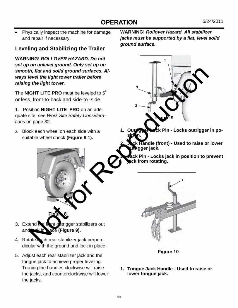
3. Extend the front outrigger stabilizers out and lock in place (Figure 9).
4. Rotate each rear stabilizer jack perpen-dicular with the ground and lock in place.
5. Adjust each rear stabilizer jack and the tongue jack to achieve proper leveling. Turning the handles clockwise will raise the jacks, and counterclockwise will lower the jacks.
WARNING! Rollover Hazard. All stabilizer jacks must be supported by a flat, level solid ground surface.
1. Outrigger Lock Pin - Locks outrigger in po-sition.
2. Jack Handle (front) - Used to raise or lower outrigger jack.
3. Jack Pin - Locks jack in position to prevent jack from rotating.
1. Tongue Jack Handle - Used to raise or lower tongue jack.
1
Figure 8
Figure 9
1
2
3
Figure 10
1
Not for
Rep
roduc
tion
34
5/24/2011 OPERATION
Not for
Rep
roduc
tion
35
5/24/2011 OPERATION
Engine Control Panels
The engine control panel consist of the engine start/stop key and hour meter.
CAT Control Panel - Manual Winch
1. Hour Meter - Shows the Total elapsed hours of engine operation.
2. Key Switch (Key start models only).
1
2
Figure 12
CAT Control Panel - Electric Winch
1. Hour Meter - Shows the Total elapsed hours of engine operation.
2. Key Switch (Key start models only).
3. Voltmeter
1
2
3
Figure 12A
Not for
Rep
roduc
tion
36
5/24/2011
KOHLER
Control Panel - Manual or electric Winch
KOHLER Control Panel
1. Engine Warning Indicator Lights.
2. Hour Meter - Shows the total elapsed hours of engine operation.
3. Key Switch.
4. Push Breaker. (Electric Winch only)
5. Toggle switch. (Electric Winch only)
Figure 13
1
2
3
KUBOTA Control Panel
Manual Winch
Figure 14
1. Hour Meter - Shows the total elapsed hours of engine operation.
2. Key Switch.
4 5
1
2
OPERATION
Not for
Rep
roduc
tion
37
5/24/2011 OPERATION
KUBOTA Deep Sea Control Panel (OPTION)
Figure 15
1. Main Panel ON/OFF Switch.
2. Hour Meter - Shows the total elapsed hours of engine operation.
3. Start Button.
4. Engine Warning Indicator Lights.
5. Glow Plug Indicator.
6. Push button breaker.
7. Electric winch switch.
1
2 4
5
3
6
7
Not for
Rep
roduc
tion
38
5/24/2011 OPERATION
Starting the Engine
The Starting procedure is different De-pending on the engine model used. Refer to your Engine Operator’s Manual for the starting procedure.
Cold - Weather Starting
The cold - weather Staring procedure is different Depending on the engine model used. Refer to your Engine Operator’s Manual for the cold - starting procedure.
If Engine has Run Out of Fuel
1. Refill the fuel tank.
2. Refer to your Engine Operator’s Manual for the starting procedure.
Notice: Do not operate starter for more than 10 seconds without allowing 30 sec-onds to pass between starting attempts. Possible starter damage could result from excessive heat caused by cranking too long.
Notice: If the engine develops sufficient speed to disengage the starter but does not keep running (a false start), the engine rotation must be allowed to come to a complete stop before attempting to restart the engine.
If starter is engaged while the flywheels rotating, the starter pinion and flywheel ring gear may clash, resulting in damage to the starter or flywheel ring gear.
Stopping the Engine
The engine stopping procedure may differ depending on the engine model. Refer to your Engine Operator’s Manual for engine stopping procedures.
Automatic Engine shutdown System
The engine is equipped with an automatic engine shutdown system to prevent excessive engine damage in the event of a low oil or overheat con-dition. For additional information, refer to your En-gine Operator’s Manual.
Low Oil Pressure Shutoff
Should a low oil pressure condition occur, the oil pressure sending unit breaks the circuit between the circuit between the battery and the fuel sole-noid, allowing the spring load to immediately move the fuel control to the shutoff position.
High Coolant Temperature Shutoff
Should a high coolant temperature condition oc-cur, the temperature sending unit breaks the cir-cuit between the battery and the fuel solenoid, allowing the spring load to immediately move the fuel control to the shutoff position.
8.
32.
Not for
Rep
roduc
tion
39
5/24/2011 OPERATION
Light Bar and Light Fixture Adjust-ment
Lights - Work Site Adjustment
The light fixtures must be adjusted to the de-sired work angle before raising the tower.
With the light tower fully lowered and the lights off, the light fixtures can be manually rotated into the desired working position.
To adjust each light fixture, manually swivel each light fixture at its base into the desired working position. (Figure 17).
1
1 - Grasp light fixture here to adjust.
Figure 17 Not for
Rep
roduc
tion
40
5/24/2011 OPERATION
RAISING MANUAL WINCH MAST, RAISING AND LOWERING LIGHTS
Manual Winch Light Tower
NOTE; The manual winch tower can be raised and extended by operating two hand crank winches. One winch, mounted with the handle extending through the side of the trailer frame, raises and lowers the mast from the horizontal towing position to the vertical position and back. The second winch mounted on the tower ex-tends and retracts the telescopic sections.
Raising
1. Before raising the light tower, adjust the tower lights to the desired work position; see Light Bar and Light Fixture Adjustment on page 38.
2. Turn the lights off; see Light Control Panel on page 40.
3. Release the pin that secures the mast to the rear mast support.
4. Operate the hand crank on the right side of the trailer to raise the mast from horizontal to vertical.
5. Turn lower black knob counterclockwise and engage latch in strike plate. Turn lower knob clockwise to retighten.
6. Operate the hand crank winch on the tower clockwise to raise the lights vertically.
7. To rotate lights, turn upper black knob coun-terclockwise and turn the tower with handles provided.
Lowering
1. Turn lights off; see Light Control Panel on page 40.
2. Loosen upper black knob and rotate tower until handles they are parallel with the front of the trailer and retighten knob.
3. Operate upper hand crank winch counter-clockwise to lower the lights to the lowest vertical position.
4. Operate lower hand crank winch on side of trailer clockwise to take up any slack in the cable.
5. Turn lower black knob counterclockwise and lift to release the latch from the strike plate. Retighten the knob with the latch disen-gaged from the strike plate.
6. Operate the lower hand crank on the side of the trailer counterclockwise to lower the mast into the horizontal towing position.
7. Secure light cords into hook on the rear tower support.
8. Secure rear support release pin, locking mast to rear tower support for towing.
1
2
3
4
5
6
1. Manual Winch Tower.
2. Rear Support Release Pin - locks tower in position for towing, trailering or lifting.
3. Lower Hand Crank Winch - raising and low-ering mast.
4. Upper hank Crank Winch - raising and low-ering lights.
5. Mast Locking Pin - locks mast in vertical po-sition.
7. Handles - used to turn tower to desired posi-tion.
Figure 18a
7
Not for
Rep
roduc
tion
41
5/24/2011 OPERATION OPERATION
Light Control Panel
The tower light control panel consist of the breaker switches.
The four light fixtures are controlled and pro-tected by four breaker switches located on the light control panel.
SHUTDOWN PROCEDURE
Shutdown - Short period
When shutting down the light tower for a short period, perform the following procedures.
1. With the lights off, lower the light tower to the full DOWN position; see Raising and Lowering the Light Tower on page 39.
2. Turn the engine off. Refer to your Engine Op-erator’s Manual for stopping procedure.
Shutdown - Long - Term or Prepare for Trail-ering
When shutting down the light tower for long peri-ods of time or when preparing to trailer; see Long - Term Storage section on page 47 or Shutdown - Prepare for Trailering section on page 16.
AUXILIARY AC OUTLET OPERATION
Depending on model options, the 240VAC 1 - phase outlet is equipped with two 240VAC outlet and one 110VAC GFCI outlets for powering ac-cessories from the generator. Power is supplied to the outlets only when the engine / generator is running and the main circuit breaker is in the ON position.
The 240VAC outlet is protected by a 30A circuit breaker.
The 110VAC GFCI outlet is protected by a 20A push button type circuit breaker.
If any of the outlet circuit breakers trip, switch off the lights, remove the load to the outlets and wait 10 minutes for the bulbs to cool before turning them back on.
1. Disconnect the load from the outlet.
2. Turn off the tower lights (if used).
1
Figure 20
1. Light Breaker Switches.
Lights On
Before turning the lights on, the engine must be running and should be allowed to reach normal operating temperature.
Turn one or more light breaker switches to the ON position.
Lights Off
Turn all light breaker switches to the OFF po-sition.
Not for
Rep
roduc
tion
42
5/24/2011 OPERATION OPERATION 3. Correct the excessive load problem and
wait 10 minutes, to allow the generator to
cool down before reconnecting the load.
Outlets with circuit breakers 50Hz
Outlets with circuit breakers 60Hz
1. 20A push button Circuit Breaker.
2. 20A GFCI Receptacle.
3. 30A DPST Circuit Breaker.
4. 30A 250V Twistlock Receptacle.
1
2
1. Shucko Receptacle
2. 15A DPST Circuit Breaker.
1
2
1
2
3
4
Not for
Rep
roduc
tion
43
5/24/2011 MAINTENANCE MAINTENANCE
Before performing any maintenance proce-dures, read Safety on page 8.
Scheduled maintenance prevents unexpected downtime, reduces the number of accidents due to poor equipment performance and helps extend the life of the light tower.
Proper maintenance and care of your light tower and trailer is a must for safe and reliable operation. Use the following maintenance and care guidelines in addition to those scheduled by your shop equipment maintenance sched-ule.
Where equipment is operated under severe conditions (very dusty, extreme heat or cold, etc.), affected items should be serviced more frequently.
ENGINE
Refer to the Engine Operator’s Manual for all engine scheduled maintenance procedures.
Changing and Adding Engine Oil
Use a high - quality engine oil of API (American Petroleum Institute) service class CC/CD/CE. Refer to the Engine Operator’s Manual for detailed engine oil specifications and service procedures.
All models are equipped with remote oil drains.
Engine Filters
Refer to the Engine Operator’s Manual for air, oil and fuel filter service procedures.
ELECTRICAL SYSTEM
Refer to the Generator Operator’s Manual for all generator schedule maintenance procedures.
Ballast Panel
The ballast panel is located on the left, front side of the light tower trailer. The ballast panel can be accessed by removing the front panel cover. The ballast panel contains the four tower light lamp ballast and capacitors. For additional wiring infor-mation, see 4 Light Ballast on page 58 - 59.
Not for
Rep
roduc
tion
44
5/24/2011 MAINTENANCE
The Safety messages that follow have WARNING level Electrocution Hazards.
Only qualified electricians should ser-vice or perform replacement proce-dures. Ballast and capacitors are capa-ble of discharging high voltage. Always use appropriate personal safety cloth-ing and gear when servicing electrical components.
High voltage is present when engine is running. Never attempt to service elec-trical components while engine is run-ning.
Do not operate the light tower if the in-sulation on the electrical wiring is cut or worn, or if bare wires are exposed. Repair or replace damaged wiring be-fore starting the engine.
1
2
50Hz Ballast Panel
1. Lamp Ballast
2. Capacitors
60Hz Ballast Panel
1. Lamp Ballast
2. Capacitors
1
2
60Hz HPS Ballast Panel
1. Lamp Ballast
2. Capacitors
1
2
Not for
Rep
roduc
tion
45
5/24/2011 MAINTENANCE
Not for
Rep
roduc
tion
46
5/24/2011 MAINTENANCE
Not for
Rep
roduc
tion
47
5/24/2011 MAINTENANCE
Not for
Rep
roduc
tion
48
5/24/2011 MAINTENANCE
Not for
Rep
roduc
tion
49
5/24/2011 MAINTENANCE
CLEANING
Keeping the light tower clean is important to ensure proper operation. Dirt and dust buildup acts as an insulator and may cause the en-gine, generator and light assemblies to oper-ate at excessively high temperatures.
Use the following as cleaning guidelines:
Use caution when using compressed air or water / steam pressure washers. Do not pressure - clean electrical components, as this may damage electrical components.
Clean the light tower and remove all dust dirt or other foreign material.
Inspect and clean the cooling air intake and exhaust louvers of the enclosure. Make sure they are clean. Remove dirt or any buildup that may restrict the cooling air flow.
Clean the light tower and its components with a damp cloth or sponge.
Inspect and clean all engine linkages so they operate properly.
Cleaning and Draining the Trailer bilg - (Artic Specials Only)
All Allmand NIGHT LITE PRO light towers contain a sealed bilge designed to catch fuel, oil or coolant spills. Should a spill occur, posi-tion a suitable container beneath the unit and remove the bilge drain plug. After the fluid has been drained, reinstall the drain plug and dis-pose of the fluid properly in accordance with EPA or other governmental guidelines.
Not for
Rep
roduc
tion
50
5/24/2011 TROUBLESHOOTING
8.
Not for
Rep
roduc
tion
51
5/24/2011 MAINTENANCE RECORD DATE SERVICE DESCRIPTION SERVICED
BY
Not for
Rep
roduc
tion
52
5/24/2011 KUBOTA W/ RELAY CONTROL WIRING SCHEMATIC