TOME VI (year 2008), FASCICULE 3, (ISSN 1584 – 2673) 245 REVISING ENGINE HEAT TRANSFER 1. Antonio José TORREGROSA, 1. Pablo César OLMEDA, 2. Carlos Alberto ROMERO 1. CMT Motores Térmicos, UNIVERSIDAD POLITÉCNICA DE VALENCIA. Camino de Vera s/n 46022, Valencia, SPAIN 2. Escuela de Tecnología Mecánica, UNIVERSIDAD TECNOLÓGICA DE PEREIRA. A. A. 97, Pereira, COLOMBIA Abstract: While the problems of thermal stresses can be addressed by means of controlling the engine coolant temperatures, the improvement of thermo-dynamical efficiency and emissions control is more directly related to the processes that take place inside the cylinder. Hence, great attention is devoted to the problems related to engine heat transfer. This field of engine research encompasses topics such as the surface heat transfer, the distribution of temperature throughout the in-cylinder gas, the temperature profile of gases near walls, boundary layer temperature distribution and boundary layer thickness, flame and spray wall thermal interactions, and soot radiation. The ability to accurately predict and diagnose heat transfer is vital for the design of efficient engine chambers. Borman and Nishiwaki [1] conducted the most important and comprehensive review available in the open literature. In this review Borman and Nishiwaki addressed all of the heat transfer issues that are critical to the successful development of combustion engines. It is the modest purpose of the present work to give a limited update of the aforementioned review [1]. Making use of the published literature the relevant to as advances and evolution of the problem, from the time when the mentioned review was publicized are commented. It can be said in advance, that the conclusions drawn here are qualitatively similar to those expressed in their time by Borman and Nishiwaki, with the differences resulted from the application of more sophisticated instrumentation and computational tools and their higher resolution results. The summaries presented do not necessarily contain all the useful information in the works reviewed, as information not related to heat transfer research has not been included. KEYWORDS: review, heat transfer, modeling, combustion engines. 1. INTRODUCTION The heat flux from the working gases to the walls varies during the working cycle from small negative values during charge exchange to positive values in the range of MW/m 2 during the combustion period [1.]. The heat transfer in the combustion engines is a transitory, three-dimensional phenomenon, in addition with big variations among two consecutive cycles of engine, partly owed to the cycle to cycle variation of the pressure and temperature of the gases in the cylinder. The problem continues representing today a challenge for the engine modellers and experimenters, for the modern computational technologies based on finite elements algorithms, and for the modern instrumentation. Numerous studies aiming at a deeper understanding of the engine heat transfer phenomena have been undertaken using recent developments in experimental techniques, simulation and diagnostic models [6.]-[19.]. These investigations have covered intake flow motion, compression temperatures, flame temperatures, instantaneous wall surface temperatures, heat transfer coefficients, and deposit studies. The heat transfer process between the working gas and its surroundings consists of two parts: heat transfer from gas to wall and heat transfer from wall to coolant and oil, both are flow receiver and flow controller
Transcript
TOME VI (year 2008), FASCICULE 3, (ISSN 1584 – 2673)
245
REVISING ENGINE HEAT TRANSFER
1.Antonio José TORREGROSA, 1.Pablo César OLMEDA, 2.Carlos Alberto ROMERO
1.CMT Motores Térmicos, UNIVERSIDAD POLITÉCNICA DE VALENCIA. Camino de Vera s/n 46022, Valencia, SPAIN
2.Escuela de Tecnología Mecánica, UNIVERSIDAD TECNOLÓGICA DE PEREIRA. A. A. 97, Pereira, COLOMBIA
Abstract: While the problems of thermal stresses can be addressed by means of controlling the engine coolant temperatures, the improvement of thermo-dynamical efficiency and emissions control is more directly related to the processes that take place inside the cylinder. Hence, great attention is devoted to the problems related to engine heat transfer. This field of engine research encompasses topics such as the surface heat transfer, the distribution of temperature throughout the in-cylinder gas, the temperature profile of gases near walls, boundary layer temperature distribution and boundary layer thickness, flame and spray wall thermal interactions, and soot radiation. The ability to accurately predict and diagnose heat transfer is vital for the design of efficient engine chambers. Borman and Nishiwaki [1] conducted the most important and comprehensive review available in the open literature. In this review Borman and Nishiwaki addressed all of the heat transfer issues that are critical to the successful development of combustion engines. It is the modest purpose of the present work to give a limited update of the aforementioned review [1]. Making use of the published literature the relevant to as advances and evolution of the problem, from the time when the mentioned review was publicized are commented. It can be said in advance, that the conclusions drawn here are qualitatively similar to those expressed in their time by Borman and Nishiwaki, with the differences resulted from the application of more sophisticated instrumentation and computational tools and their higher resolution results. The summaries presented do not necessarily contain all the useful information in the works reviewed, as information not related to heat transfer research has not been included. KEYWORDS: review, heat transfer, modeling, combustion engines.
1. INTRODUCTION The heat flux from the working gases to the walls varies during the working cycle from
small negative values during charge exchange to positive values in the range of MW/m2 during the combustion period [1.]. The heat transfer in the combustion engines is a transitory, three-dimensional phenomenon, in addition with big variations among two consecutive cycles of engine, partly owed to the cycle to cycle variation of the pressure and temperature of the gases in the cylinder. The problem continues representing today a challenge for the engine modellers and experimenters, for the modern computational technologies based on finite elements algorithms, and for the modern instrumentation.
Numerous studies aiming at a deeper understanding of the engine heat transfer phenomena have been undertaken using recent developments in experimental techniques, simulation and diagnostic models [6.]-[19.]. These investigations have covered intake flow motion, compression temperatures, flame temperatures, instantaneous wall surface temperatures, heat transfer coefficients, and deposit studies. The heat transfer process between the working gas and its surroundings consists of two parts: heat transfer from gas to wall and heat transfer from wall to coolant and oil, both are flow receiver and flow controller
ANNALS OF THE FACULTY OF ENGINEERING HUNEDOARA – JOURNAL OF ENGINEERING. TOME VI (year 2008). Fascicule 3 (ISSN 1584 – 2673)
elements. The effects of heat transfer on the engine performance and mechanical design drive most of the research works on engine heat transfer. Experimental and theoretical works are carried out to characterize the engine thermal behaviour with the aims of improving engine performance, reducing fuel consumption and emissions, and also improving entire vehicle thermal management. In particular the development of computational codes and commercial software has boosted the necessity of quantifying and experimentally validate the engine heat transfer in all the aspects mentioned over the entire engine cycle operation.
For every location of the combustion chamber wall the rationale to find the heat flux through that surface involves the solution of the energy equation. The simplified energy equation, consisting on the storage, conduction, convection, pressure work, and heat generation (by convection and radiation) terms is written, according to Borman and Nishiwaki [1.], in dimensionless form with the assumption of constant heat conductivity, constant specific heat, spatially uniform pressure and treating chemical energy as a volume heat source, neglecting diffusion and convection of different species as
**
*
****2
*
qd
dppT1TvT
PrRe1T &+
τ⎟⎟⎠
⎞⎜⎜⎝
⎛γ−γ
+∇−∇=τ∂
∂, (1)
Where p*= p/p0, T*= T/T0 y v* = v/v0 are nondimensional pressure, temperature and velocity, scaled by the reference values of p0, T0 and v0, respectively; τ = tv0/D, Re = ρv0D/μ, Pr = cpμ/k y γ = cp/cv.
Solution of equation (1) along with the continuity and momentum equations should allow a correlation for the Nusselt number in terms of the Reynolds and Prandtl numbers, but additional terms, due to the presence of p* and q* are also important. Reynolds’ number is based on the time dependent density. The term dp*/dτ can reach very high values during combustion. The coefficient of this term is the reciprocal of the gas density (specific volume) and, hence, suffers considerable variations through boundary layer over the time. It is not likely that all parameters can be incorporated in a universal global model, a reason for obtaining and using correlations of the form . nReNu =
The complexities and some times the insufficiency of information to solve the energy equation (1) raise many difficulties in modelling engine heat transfer. Thus, despite the progress in theoretical, experimental and computational studies [11.],[12.], most of the used heat transfer models avoid the energy equation approach solution, and make use of either experimental or dimensional analysis based correlations to model the in-cylinder heat transfer.
Radiant heat transfer model is included in the global models sometimes lumped with the convective coefficient and sometimes as a separate term. Here, the review of heat transfer will be limited to the scope of the in-cylinder space.
With the above mentioned and not getting into the details of the models used in the research works, some of the most relevant formulae used to model the in-cylinder heat transfer is presented in the following sections of the present paper, according to a grouping criterion, as follows:
Global (one zone) thermodynamic models. Zonal (more than one zone) thermodynamic models. One-dimensional analytical and numerical fluid-dynamic models. Multidimensional numerical fluid-dynamic (CFD) models. Radiative heat transfer models.
At the end of the paper some comments about heat transfer modelling research are made.
2. GLOBAL MODELS Global heat transfer models correlate instantaneous convection heat transfer
coefficients in the same form as steady heat transfer correlations found in flows over flat plates or in pipes. In these convection dominated flows, the boundary layers are fully developed and in equilibrium with each other, so an analogy between the transport of energy and momentum is valid. They typically correlate the Nusselt and Reynolds numbers in a form like (2), where the characteristic length is either taken as the current nReCNu ⋅=
246
ANNALS OF THE FACULTY OF ENGINEERING HUNEDOARA – JOURNAL OF ENGINEERING. TOME VI (year 2008). Fascicule 3 (ISSN 1584 – 2673)
combustion chamber height or the bore, and the velocity is a function of the mean piston speed. Transport coefficients k (conductivity) and ν (viscosity), are usually evaluated using averaged values for the gas and wall temperatures. With these models it is sought an averaged heat transfer coefficient assumed valid for all the surfaces of the combustion chamber with which the total instant heat flux from the lumped gases to the chamber wall could be calculated (Newtonian equation)
( )wTThq −= (3) In general, global models are not used to describe the details of local and unsteady
heat transfer effects. They are developed to address the overall effects on the state of the whole cylinder gas while employing the quasi-steady state assumption. They have been suitable for engine cycle simulation purposes, which also deal with the state of the whole cylinder gas and predict the overall engine performance such as engine output, fuel consumption, total heat loss, thermal load, exhaust temperature, etc. From global models it is not expected to have local and instantaneous resolution of temperature and heat fluxes, even though the data from which they were obtained were typically instantaneous local values.
In their review, in 1987 Borman and Nishiwaki [1.] addressed all of the heat transfer issues that are critical to the successful development of combustion engines, making useful comments about the major works published until that time in relation to in-cylinder heat transfer phenomena and thermal measurements. In particular, Borman and Nishiwaki reviewed the heat transfer models of Nusselt (1923), Briling (1935), Eichelberg (1939), Annand (1963), Sitkei (1962), Annand and Ma (1970), Woschni (1967), LeFeuvre (1969), Morel and Keribar (1985), as well as the experimental works of Eichelberg (1939), Bendersky (1953), Oberbye et al. (1961), Oguri and Aizawa (1972), Dent and Suliaman (1977), Enomoto and Furuhama (1985). Recently Finol and Robinson [2.] presented a paper, where the most important empirical correlations used for calculating the in-cylinder heat transfer in modern Diesel engines were also reviewed. Though the authors added nothing new with respect to the work of Borman and Nishiwaki, concluding that the fundamental suitability of empirical models in representing the highly complex processes of in-cylinder heat transfer is questionable, they agreed that the models have steadily improved owing to contributions from numerous investigators and are still broadly used.
Woschni equation [1.][51.] is the most widely used correlation which was also based on the similarity law of steady turbulent heat transfer. After assuming that the gas thermal conductivity k is proportional to T0,75, where T is the average gas temperature and the gas dynamic viscosity μ being proportional to T0,62, choosing the cylinder bore diameter D as the characteristic length, Woschni arrived at an equation for the heat transfer coefficient (expressed in kW/m2K) :
53,08,08,02,0 TWpD820,0h −−= ; ( ⎥⎦
⎤⎢⎣
⎡−+= 0
11
1s2m1 pp
VpTVCCCW ) (4)
Woschni states that the characteristic speed W depends on two terms. One is due to piston motion and is modeled as the mean piston speed Cm [m/s]. The other term is due to swirl originating from the combustion event, which is modeled as a function of the pressure rise due to combustion, i.e. p − p0 where p0 is the motored pressure. For the gas exchange process C1 = 6,18, C2 = 0. For the compression process C1 = 2,28, C2 = 0. For combustion and expansion processes C1 = 2,28, C2 = 3,24⋅10-3. p0 is the motored pressure, in MPa, Vs is the volume swept by the piston, in m3. T1, V1 y p1 are determined for a known reference position for which pressure and temperature are known, the intake valve closing or the start of combustion time, for instance. Although the Woschni equation was derived for the heat transfer in stationary turbulent flows, it also incorporates in a lumped manner all the effects of convection and radiation. Later on Woschni added a “swirl” term to his equation, modifying the expression for the C1 coefficient. For the gas Exchange process, C1 = 6,18 + 0,417Cu/Cm; for the remaining part of the cycle C1 = 2,28 + 0,308/Cm; Cu =πDnD, and nD is the rotational speed of the pad used in the test bench for the swirl. The Woschni correlation incorporates all the effects of convection and radiation in a lumped form, although the equation was derived in the form of steady turbulent convective heat transfer.
247
ANNALS OF THE FACULTY OF ENGINEERING HUNEDOARA – JOURNAL OF ENGINEERING. TOME VI (year 2008). Fascicule 3 (ISSN 1584 – 2673)
Hohenberg [54.] modified Woschni equation, to give better prediction of time averaged heat fluxes obtained from one-dimensional heat flux probes. The modifications included the use of instantaneous cylinder volume instead of cylinder bore, and changes of the effective velocity, W, and of the exponent of the temperature term.
Though Woschni correlation is the most widespread used, the use of other correlations is also frequent. The variation in heat transfer correlations does not have a significant influence on the engine performance prediction. Typically, a 10 per cent error in the prediction of in-cylinder heat transfer leads to an error in the order of 1 per cent for the engine performance prediction [21.]. The global correlations described can be used for the approximate gas side boundary conditions, but at present there is no model which can give a detailed distribution of local heat transfer coefficients.
The deficiency of global models is that they do not account for a number of effects that are present in the engine environment. Some of the most important of these are unsteadiness, complex mean velocity field, compressibility, gas composition variations, and wall deposits. The unsteadiness implies that the energy and the momentum boundary layers are not necessarily in equilibrium or in a pseudo steady state, either with themselves or with each other. A strong compression in the engine affects all of the flow related properties and causes the change of the boundary layers’ thickness due to the change in working gas density. Since the velocity field is not as simple and organized as in the pipe flow or flow over a flat plate, it cannot force the boundary layers to adjust quickly enough to achieve even near equilibrium conditions.
Woschni did improve the basic theory by altering the velocity, at which the Reynolds number is based, for different processes to match the actual gas velocities. Most of the works that follow the Woschni equation have incorporated corrections to account for the factors mentioned above (Shubert et al. [60.], Guezennec et al. [59.]). Furthermore, because of the previously mentioned need for greater accuracy, many researchers have also incorporated turbulence effects into their models, with the primary differences in their approaches lying in the method of determining the gas velocity used in the correlations.
Allmendinger et al. [55.] developed a predictive model to be implemented in closed loop software applications for common rail Diesel engines, to work independently of engine maps, based on analytical solving methods. The model calculates the pressure and the temperature curve during the compression, expansion, and heat release processes, as a function of the injection timing, quantity of the injected fuel and the rail pressure, and reduce the cylinder gases temperature differential equation in a Riccati differential equation. Arguing the difficulties of implementing the Woschni model for their application, and based on the benefits of the linear relationship between the heat transfer coefficient and the temperature, the authors quantified the heat transfer coefficient with an expression in the form:
( ) ( ) ( )TbaT,h ϕ+ϕ=ϕ ; ( )( )
2
2E
22
e2
1b,a σ
ϕ−ϕ−
πσ=ϕ (5)
Thus, the model for the heat transfer coefficient relays on the resolution of a Gaussian function.
Recently Kavtaratze et al. [75.] employed the hypothesis of additivity of convective and radiative heat transfer to find the complex local heat transfer coefficient (the convective-radiative heat transfer coefficient) in the combustion chamber of an 8ChN 12/12 high-speed Diesel engine. The integral characteristics of radiative heat transfer in the combustion chamber were also calculated using the experimental data on the emissivity factor of the working medium.
3. ZONAL MODELS Global models lack the resolution to model and analyse such processes as radiation in
compression engines and knocking in spark ignition engines. Global models only allow for calculation of the mean values of the radiative heat flux on the walls of the combustion chamber and did not enable to find which parts of these walls are less or more irradiated.
248
ANNALS OF THE FACULTY OF ENGINEERING HUNEDOARA – JOURNAL OF ENGINEERING. TOME VI (year 2008). Fascicule 3 (ISSN 1584 – 2673)
More over, since convection and radiation heat transfer mechanisms are driven by different temperature differences, a heat transfer model based on a single-zone combustion model is practical only for global balances. At least the use of a two-zone combustion model is required to obtain knowledge of the temperatures in the fresh air zone and the burned zone in order to consider the two transfer mechanisms separately.
In spark ignition engines at the time of knock, the largest heat fluxes are associated with locations on the cylinder walls, where the flame is locally quenching. These reasons, among others of the same importance have powered the development of zonal models to study the combustion and heat transfer processes. The development of zonal models has been a necessity also to assess the complex flame-wall, and spray-wall interactions. Some of the zonal models used for calculating heat losses, have been those ones implemented by Poulos and Heywood [56.], Bargende [58.], and Morel and Keribar [6.].
Poulos and Heywood, in 1983 [56.], incorporated turbulence effects into a cycle simulation for a gasoline engine. They calculated the effective speed as
( ) 2/12p
eff 4tV
k2K2U⎥⎥⎦
⎤
⎢⎢⎣
⎡++= (6)
Here K and k are the kinetic energy of the mean flow and the turbulence, respectively. The characteristic length is used as the macro-scale of turbulence.
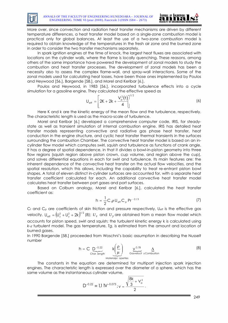
Morel and Keribar [6.] developed a comprehensive computer code, IRIS, for steady-state as well as transient simulation of internal combustion engine. IRIS has detailed heat transfer models representing convective and radiative gas phase heat transfer, heat conduction in the engine structure, and cyclic heat transfer thermal transients in the surfaces surrounding the combustion Chamber. The convective heat transfer model is based on an in-cylinder flow model which computes swirl, squish and turbulence as functions of crank angle. It has a degree of spatial dependence, in that it divides a bowl-in-piston geometry into three flow regions (squish region above piston crown, cup volume, and region above the cup), and solves differential equations in each for swirl and turbulence. Its main features are: the inherent dependence of the convective heat transfer on the actual flow velocities, and the spatial resolution, which this allows, including the capability to treat re-entrant piston bowl shapes. A total of eleven distinct in-cylinder surfaces are accounted for, with a separate heat transfer coefficient calculated for each. An additional convective heat transfer model calculates heat transfer between port gases and port surfaces.
Based on Colburn analogy, Morel and Keribar [6.], calculated the heat transfer coefficient as:
3/2pefff PrCUC
21h −ρ= (7)
Cf and Cp are coefficients of skin friction and pressure respectively, Ueff is the effective gas velocity, (8); and are obtained from a mean flow model which accounts for piston speed, swirl and squish; the turbulent kinetic energy k is calculated using k-ε turbulent model. The gas temperature, Tg, is estimated from the amount and location of burned gases.
( 2/12y
2zeff k2UUU ++= ) zU yU
In 1990 Bargende [58.] proceeded from Woschni’s basic assumption in describing the Nusselt number
CombustionyGasvelocit
78.0
opertiesMaterialpr
length.Char
22.0 vkDCh Δ⎟⎟⎠
⎞⎜⎜⎝
⎛μρ
= −
321321
(8)
The constants in the equation are determined for multiport injection spark injection engines. The characteristic length is expressed over the diameter of a sphere, which has the same volume as the instantaneous cylinder volume,
073,022,0 V11,1D −− ≡ ;2
V3k8
v
2p+
= .
249
ANNALS OF THE FACULTY OF ENGINEERING HUNEDOARA – JOURNAL OF ENGINEERING. TOME VI (year 2008). Fascicule 3 (ISSN 1584 – 2673)
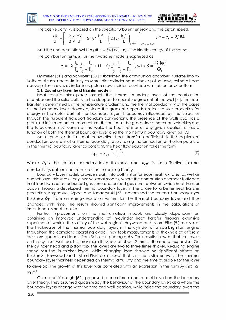
The gas velocity, v, is based on the specific turbulent energy and the piston speed.
EVOIVCTDC
5,1s
5,1
Lk184,2
Lk184,2
dtdV
Vk
32
dtdk
≤ϕ≤>ϕ ⎥⎥⎦
⎤
⎢⎢⎣
⎡⎟⎟⎠
⎞⎜⎜⎝
⎛+−−= ; 184,2== sεε
And the characteristic swirl length ( )3 6 VL π= ; is the kinetic energy of the squish. sk
The combustion term, Δ, for the two zone model is expressed as
( )⎥⎥⎦
⎤
⎢⎢⎣
⎡
−−
−+−−
=Δwg
wub
g
ub
wg
wb
g
b
TTTT
TTX1
TTTT
TTX , with
( )f
f
QQX ϕ
=
Eiglmeier [61.] and Schubert [60.] subdivided the combustion chamber surface into six isothermal subsurfaces similarly as Morel did: cylinder head above piston bowl, cylinder head above piston crown, cylinder liner, piston crown, piston bowl side wall, piston bowl bottom.
3.1. Boundary layer heat transfer model. Heat transfer takes place through the thermal boundary layers of the combustion
chamber and the solid walls with the steepest temperature gradient at the wall [9.]. The heat transfer is determined by the temperature gradient and the thermal conductivity of the gases at the boundary layer. However, since the gradient depends on the transfer properties for energy in the outer part of the boundary layer, it becomes influenced by the velocities through the turbulent transport (random convection). The presence of the walls also has a profound influence on the momentum distribution in the gases since the mean velocities and the turbulence must vanish at the walls. The heat transfer at any given location is thus a function of both the thermal boundary layer and the momentum boundary layer [5.],[9.].
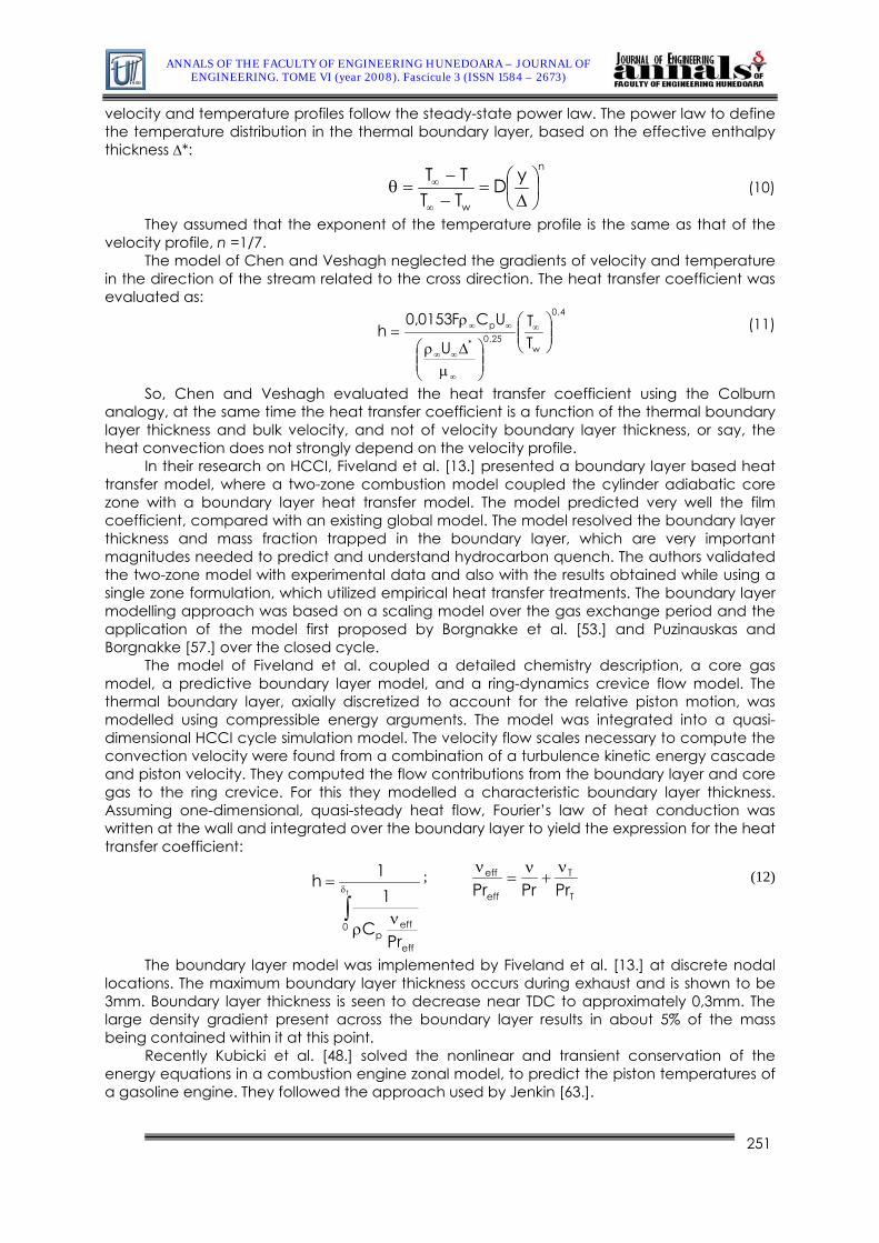
An alternative to a local convective heat transfer coefficient is the equivalent conduction constant of a thermal boundary layer. Taking the distribution of the temperature in the thermal boundary layer as constant, the heat flow equation takes the form
T
wgeffw
TTkq
δ
−= (9)
Where Tδ is the thermal boundary layer thickness, and is the effective thermal
conductivity, determined from turbulent modelling theory. effk
Boundary layer models provide insight into both instantaneous heat flux rates, as well as quench layer thickness. They involve zonal models, where the combustion chamber is divided in at least two zones, unburned gas zone and burned gas core, between which heat transfer occurs through a developed thermal boundary layer. In the chase for a better heat transfer prediction, Borgnakke, Arpaci and Tabaczynski [53.] determined the thermal boundary layer thickness, Tδ , from an energy equation written for the thermal boundary layer and thus changed with time. The results showed significant improvements in the calculations of instantaneous heat transfer.
Further improvements on the mathematical models are closely dependant on obtaining an improved understanding of in-cylinder heat transfer through extensive experimental work in the vicinity of the wall regions. Heywood and Lyford-Pike [5.] measured the thicknesses of the thermal boundary layers in the cylinder of a spark-ignition engine throughout the complete operating cycle. They took measurements of thickness at different locations, speeds and loads, from Schlieren photographs. Their results showed that the layers on the cylinder wall reach a maximum thickness of about 2 mm at the end of expansion. On the cylinder head and piston top, the layers are two to three times thicker. Reducing engine speed resulted in thicker layers, while changing load showed no significant effects on thickness. Heywood and Lyford-Pike concluded that on the cylinder wall, the thermal boundary layer thickness depended on thermal diffusivity and the time available for the layer to develop. The growth of this layer was correlated with an expression in the form tT αδ α
. 2,0ReChen and Veshagh [62.] proposed a one-dimensional model based on the boundary
layer theory. They assumed quasi-steady the behaviour of the boundary layer: as a whole the boundary layers change with the time and wall location, while inside the boundary layers the
250
ANNALS OF THE FACULTY OF ENGINEERING HUNEDOARA – JOURNAL OF ENGINEERING. TOME VI (year 2008). Fascicule 3 (ISSN 1584 – 2673)
velocity and temperature profiles follow the steady-state power law. The power law to define the temperature distribution in the thermal boundary layer, based on the effective enthalpy thickness Δ*:
n
w
yDTTTT
⎟⎠⎞
⎜⎝⎛Δ
=−−
=θ∞
∞ (10)
They assumed that the exponent of the temperature profile is the same as that of the velocity profile, n =1/7.
The model of Chen and Veshagh neglected the gradients of velocity and temperature in the direction of the stream related to the cross direction. The heat transfer coefficient was evaluated as:
4,0
w25,0*
p
TT
U
UCF0153,0h ⎟⎟
⎠
⎞⎜⎜⎝
⎛
⎟⎟⎠
⎞⎜⎜⎝
⎛μ
Δρ
ρ= ∞
∞
∞∞
∞∞ (11)
So, Chen and Veshagh evaluated the heat transfer coefficient using the Colburn analogy, at the same time the heat transfer coefficient is a function of the thermal boundary layer thickness and bulk velocity, and not of velocity boundary layer thickness, or say, the heat convection does not strongly depend on the velocity profile.
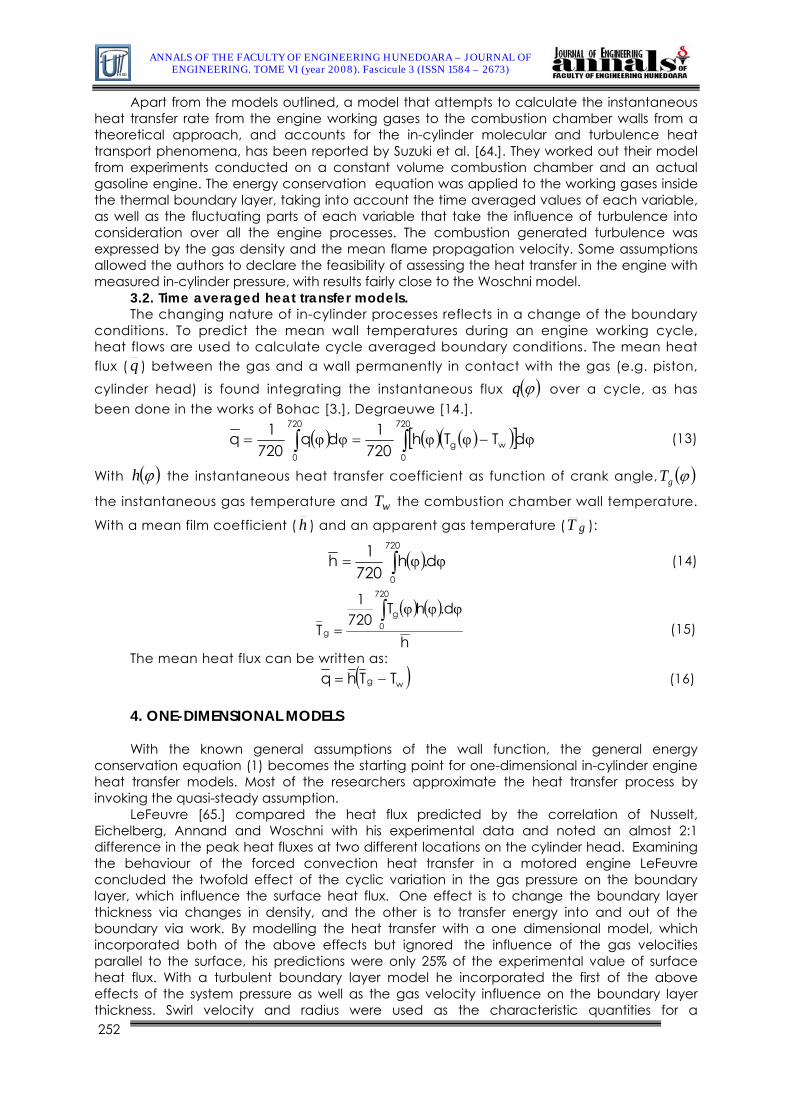
In their research on HCCI, Fiveland et al. [13.] presented a boundary layer based heat transfer model, where a two-zone combustion model coupled the cylinder adiabatic core zone with a boundary layer heat transfer model. The model predicted very well the film coefficient, compared with an existing global model. The model resolved the boundary layer thickness and mass fraction trapped in the boundary layer, which are very important magnitudes needed to predict and understand hydrocarbon quench. The authors validated the two-zone model with experimental data and also with the results obtained while using a single zone formulation, which utilized empirical heat transfer treatments. The boundary layer modelling approach was based on a scaling model over the gas exchange period and the application of the model first proposed by Borgnakke et al. [53.] and Puzinauskas and Borgnakke [57.] over the closed cycle.
The model of Fiveland et al. coupled a detailed chemistry description, a core gas model, a predictive boundary layer model, and a ring-dynamics crevice flow model. The thermal boundary layer, axially discretized to account for the relative piston motion, was modelled using compressible energy arguments. The model was integrated into a quasi-dimensional HCCI cycle simulation model. The velocity flow scales necessary to compute the convection velocity were found from a combination of a turbulence kinetic energy cascade and piston velocity. They computed the flow contributions from the boundary layer and core gas to the ring crevice. For this they modelled a characteristic boundary layer thickness. Assuming one-dimensional, quasi-steady heat flow, Fourier’s law of heat conduction was written at the wall and integrated over the boundary layer to yield the expression for the heat transfer coefficient:
∫δ
νρ
=t
0
eff
effp Pr
C
11h ;
T
T
eff
eff
PrPrPrν
+ν
=ν (12)
The boundary layer model was implemented by Fiveland et al. [13.] at discrete nodal locations. The maximum boundary layer thickness occurs during exhaust and is shown to be 3mm. Boundary layer thickness is seen to decrease near TDC to approximately 0,3mm. The large density gradient present across the boundary layer results in about 5% of the mass being contained within it at this point.
Recently Kubicki et al. [48.] solved the nonlinear and transient conservation of the energy equations in a combustion engine zonal model, to predict the piston temperatures of a gasoline engine. They followed the approach used by Jenkin [63.].
251
ANNALS OF THE FACULTY OF ENGINEERING HUNEDOARA – JOURNAL OF ENGINEERING. TOME VI (year 2008). Fascicule 3 (ISSN 1584 – 2673)
Apart from the models outlined, a model that attempts to calculate the instantaneous heat transfer rate from the engine working gases to the combustion chamber walls from a theoretical approach, and accounts for the in-cylinder molecular and turbulence heat transport phenomena, has been reported by Suzuki et al. [64.]. They worked out their model from experiments conducted on a constant volume combustion chamber and an actual gasoline engine. The energy conservation equation was applied to the working gases inside the thermal boundary layer, taking into account the time averaged values of each variable, as well as the fluctuating parts of each variable that take the influence of turbulence into consideration over all the engine processes. The combustion generated turbulence was expressed by the gas density and the mean flame propagation velocity. Some assumptions allowed the authors to declare the feasibility of assessing the heat transfer in the engine with measured in-cylinder pressure, with results fairly close to the Woschni model.
3.2. Time averaged heat transfer models. The changing nature of in-cylinder processes reflects in a change of the boundary
conditions. To predict the mean wall temperatures during an engine working cycle, heat flows are used to calculate cycle averaged boundary conditions. The mean heat flux ( q ) between the gas and a wall permanently in contact with the gas (e.g. piston,
cylinder head) is found integrating the instantaneous flux ( )ϕq over a cycle, as has been done in the works of Bohac [3.], Degraeuwe [14.].
( ) ( ) ( )([ ϕ−ϕϕ=ϕϕ= ∫∫ dTTh720
1dq720
1q720
0wg
720
0
)] (13)
With ( )ϕh the instantaneous heat transfer coefficient as function of crank angle, ( )ϕgT
the instantaneous gas temperature and the combustion chamber wall temperature.
With a mean film coefficient (wT
h ) and an apparent gas temperature ( gT ):
( ) ϕϕ= ∫ d.h720
1h720
0
(14)
( ) ( )
h
d.hT720
1
T
720
0g
g
ϕϕϕ=
∫ (15)
The mean heat flux can be writte as: n ( )wg TThq −= (16)
4. ONE-DIMENSIONAL MODELS With the known general assumptions of the wall function, the general energy
conservation equation (1) becomes the starting point for one-dimensional in-cylinder engine heat transfer models. Most of the researchers approximate the heat transfer process by invoking the quasi-steady assumption.
LeFeuvre [65.] compared the heat flux predicted by the correlation of Nusselt, Eichelberg, Annand and Woschni with his experimental data and noted an almost 2:1 difference in the peak heat fluxes at two different locations on the cylinder head. Examining the behaviour of the forced convection heat transfer in a motored engine LeFeuvre concluded the twofold effect of the cyclic variation in the gas pressure on the boundary layer, which influence the surface heat flux. One effect is to change the boundary layer thickness via changes in density, and the other is to transfer energy into and out of the boundary via work. By modelling the heat transfer with a one dimensional model, which incorporated both of the above effects but ignored the influence of the gas velocities parallel to the surface, his predictions were only 25% of the experimental value of surface heat flux. With a turbulent boundary layer model he incorporated the first of the above effects of the system pressure as well as the gas velocity influence on the boundary layer thickness. Swirl velocity and radius were used as the characteristic quantities for a 252
ANNALS OF THE FACULTY OF ENGINEERING HUNEDOARA – JOURNAL OF ENGINEERING. TOME VI (year 2008). Fascicule 3 (ISSN 1584 – 2673)
dimensional analysis of the energy equation. Later Nijeweme [12.] arrived at the same conclusions. Soon after, Reitz [11.] also contributed to the study of the influence of unsteadiness and compressibility on the engine heat transfer.
Jenkins et al. [29.] coupled a quasi-dimensional engine cycle model with a one-dimensional control volume mesh, for the solution of a discretized form of the conservation of enthalpy equation in the near-wall region of a spark ignition engine. This enabled the thermal boundary layers to be accurately predicted in both the burnt and unburned charge. A k-ε turbulence model simulating the essential features of the in-cylinder flow was included. Parameters accounting for the turbulent eddy transport of momentum and enthalpy were computed from the conserved turbulence properties. The authors showed that when these values were used as input to a FEM and the near-wall conservation of enthalpy equation, the model was capable of accurately predict pressure-crank angle diagrams and near-wall temperature profiles.
Han and Reitz [11.], based on the one-dimensional energy conservation equation, developed a temperature wall function (an analytic solution to simplified turbulence equations to infer wall shear stress and heat loss to bridge the viscous sublayer region), suitable for I.C.E. density-variable turbulent flows; Turbulence in the high-Reynolds-number regions was modelled using a modified RNG k-ε model. Variations within the layer of the fluid thermo-physical properties are considered. Due to the gas density variation, the wall heat flux was found to be proportional to the logarithm of the ratio of the flow temperature to the wall temperature instead of to the arithmetic difference of the two temperatures, which is the case for incompressible flows. The temperature wall function was implemented in the KIVA-II computer code and applied to gas-wall convective heat transfer predictions in a premixed charge spark-ignition engine and a heavy-duty diesel engine. Although no comparison with any measurements was made for the Diesel engine predictions due to the lack of measured data for that engine, the heat transfer predictions indicated a significant nonuniform heat flux distribution on the cylinder head and peak heat flux values of 5-10 MW/m2 depending on the location. Higher values were found over the edge of the piston bowl. In their work, Han and Reitz found that gas compressibility affected heat flux prediction significantly. Wall heat flux can be greatly underpredicted with the use of a wall function formulated for incompressible flows. Effects of unsteadiness and chemical heat release were found to be small.
According to Han and Reitz, the formulation for wall heat flux comprises a part corresponding to the steady state solution of the equation and a part due to the unsteadiness of the heat transfer process, usssw qqq += [11.]:
( ) ( )( ) −
+
ν+−ρ=
+
+
5,2yln1,2u/G4,33y1,2TTlnTuC
q*
w*
pw
( )( ) ( )
⎪⎭
⎪⎬⎫
⎪⎩
⎪⎨⎧
θθθφ
⎥⎥⎦
⎤
⎢⎢⎣
⎡
⎟⎟
⎠
⎞
⎜⎜
⎝
⎛⎟⎟⎠
⎞⎜⎜⎝
⎛ θ−τ−−+
θ−τπμρ
⎟⎟⎠
⎞⎜⎜⎝
⎛− ∫
τγ−γ
0
us
w
*0
1
00 d
d,0d
3exp1082,01uk
ppkT (17)
Where 2/1* kCuμ
=
Han and Reitz compared the results of their model to those obtained with the standard KIVA model. The standard KIVA model uses an incompressible wall function approach. Details of the KIVA are depicted by Amsden [30.]. The KIVA model predicted much lower heat fluxes at all the monitoring locations compared with those predicted by the model of Han and Reitz.
Recently Nuutinen [33.] claimed the implementation of a new variable density formulation for wall functions. His model, as compared to the work of Han and Reitz did not assess the influence of the source terms, neither did evaluate the unsteady condition; the quality of the modified wall functions has not been tested experimentally yet. Simulations were made with four combinations of turbulence models and near wall treatments: high Reynolds number k-ε model with standard wall functions; high Reynolds number k-ε model with the new variable density wall functions, computed in user subroutines; high Reynolds number RNG k-ε model with standard wall functions; and low Reynolds number k-ε model with
253
ANNALS OF THE FACULTY OF ENGINEERING HUNEDOARA – JOURNAL OF ENGINEERING. TOME VI (year 2008). Fascicule 3 (ISSN 1584 – 2673)
hybrid wall treatment. In the hybrid wall treatment the flow field is resolved all the way down to the wall without any wall functions. The new modified variable density wall functions (MWF) predict clearly higher peak temperatures than the other standard (SWF) and hybrid (HWF) wall functions. The new wall functions also predict higher heat transfer from the charge to the piston surface, though, the author said, this traduces on a marginally higher peak pressure as compared to the corresponding simulation with standard wall functions,
Nijeweme et al. [12.] applied the energy equation to demonstrate the inconsistencies of using the law of the wall while modelling the heat transfer phenomena inside the engine cylinder. The one-dimensional energy equation in Lagrangian coordinates, correlating the Lagrangian, z, and Eulerian, y coordinates, expressed in terms of the normalized temperature
( )( )t,T
t,zT)t,z(U∞
= had the form
444 3444 2143421turbulent
t
t00
arminla
2
2
00 z
UPrPr
zpp
zU
pp
tU
⎟⎟⎠
⎞⎜⎜⎝
⎛∂∂
μμ
∂∂
α+∂∂
α=∂∂ Where pCk ρα /00 = . (18)
To solve the Energy equation Nijeweme [12] made use of the available experimental data to find the turbulent thermal conductivity, kt, the turbulent Prandtl number, Prt, and the turbulent viscosity, μt in the boundary layer. The turbulent thermal conductivity, kt, was tuned until the solution equation gave a temperature field close to the wall, such that the heat flux matched the measured surface heat flux for that location in the cylinder. Then turbulent intensities were calculated with CFD and so the thermal conductivity expression was tuned by locations. Nijeweme’s solution of the energy equation provided evidence of the negative heat flux during the expansion stroke of the piston, and also served to illustrate the relative contributions of the convective and work terms.
In the energy equation the convection term is the most important for the magnitude of the heat transfer. The pressure work term is very important for the phasing of the heat transfer. Even with a low pressure variation of about 5 bar, the heat flux is advanced by 10 º CA, compared with heat flux without the work term. The phase shift enhances the peak heat flux and is also partly responsible for the negative heat flux. To have a better prediction of the boundary layer for the compressible flow field in an internal combustion engine, in numerical models and in the direct solution of the one-dimensional energy equation, the detailed information about the turbulent Prandtl number and the turbulent gas viscosity in the boundary layer is required.
5. MULTIDIMENSIONAL MODELS Multidimensional models numerically solve the general conservation equations for
reacting fluid flows, the conservation of mass, continuity of species, momentum energy and some turbulent variables (Navier Stokes approach). The random nature of turbulence and the fact that it corresponds to highly variable space scales makes it necessary to carry out an averaging of the Navier Stokes equations in order to calculate the average quantities and their fluctuations.
Numerical computational codes (CFD), based on multidimensional modelling, have become a very valuable tool for heat transfer calculations, especially as they can provide more complete information of the in-cylinder flow pattern and behaviour than experiments or simple models can. Jennings and Morel [25.] pioneered CFD simulations. They used these tools to demonstrate the effect of the wall temperature on the temperature gradient in the vicinity of the wall. In general, the main components of numerical computational methods are: mathematical models (equations) used to describe the turbulent processes, especially the small scale features which are inaccessible to direct calculation (usually based on a wall function); discretization procedures, used to transform the differential equations of the mathematical model into algebraic relations between discrete values of velocity, pressure, temperature, located on a computing mesh which conforms to the geometry of the combustion chamber, with its moving piston and valves; solution algorithms, whose function is to solve the algebraic equations, and computer codes, which translate the numerical
254
ANNALS OF THE FACULTY OF ENGINEERING HUNEDOARA – JOURNAL OF ENGINEERING. TOME VI (year 2008). Fascicule 3 (ISSN 1584 – 2673)
algorithm into computer language and provide the interface for input and output information. Most of the current in use CFD codes employ either a wall function or a near wall modelling approach to describe near the wall flow conditions in heat transfer calculations. The three dimensional compressible averaged Navier–Stokes equations are solved on a moving mesh and turbulent fluxes are modeled by an eddy viscosity concept, using κ-ε model.
There are a number of commercial CFD packages as Fluent [66.], STAR_CD [68.], FIRE [15.], KIVA [30.],[69.] that provide good combustion engine multidimensional capability. However, the most widely used for engine simulation is the KIVA family of programs originally developed at Los Alamos National Laboratory. The basic features of the code have been well documented [30.],[69.]. KIVA-3V is a three-dimensional, multicomponent model capable of simulating multiphase flow under steady state and transient conditions. The code solves the unsteady three-dimensional compressible average Navier-Stokes equations coupled to a k-ε turbulence model. The k-ε model uses the wall function.
A general methodology followed with the CFD codes to model the heat transfer to combustion chamber walls includes the interface with FE codes. In a first stage of the methodology the first calculated engine cycle is run with constant component dependent prescribed temperatures for different parts of the engine (piston, valve seats, ports, etc.). Then, for the second cycle run, the CFD code uses the calculated by the FE code component temperatures, providing better initial conditions for following calculations [70.]. Liu and Reitz [71.] developed a two-dimensional transient Heat Conduction in Components (HCC) code, based on the Saul’yev numerical finite difference method, to calculate the temperature field existing in the combustion chambers of two Diesel engines, one of them insulated. The HCC code was combined with the KIVA-II code in an iterative loop, in which the KIVA-II code provided the instantaneous local heat flux on the combustion chamber surfaces, and the HCC code computed the time-averaged wall temperature distribution on the surfaces. After iterations, accurate combustion chamber surface temperatures were obtained. For the insulated engine, the predicted temperature swing at a point on the cylinder head was found to be consistent with the available measured temperature data for motored and fired cases. For the baseline engine, the spatially varying combustion chamber wall temperatures were found to influence both engine total heat transfer and engine-out NOx prediction significantly.
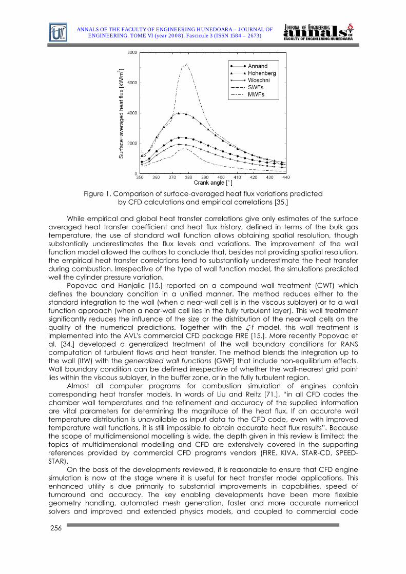
Kleemann et al. [35.] used a STAR-CD CFD simulation code, as well as experimental measurements, to determine the magnitude and origins of local spatial and temporal surface heat flux variations in a HPP Diesel engine. Their investigations included the use of standard and modified wall function models of the flow and thermal boundary layers. They performed a full induction simulation using the measured pressure histories in the intake and exhaust ports as boundary conditions, and derived the wall temperatures from measurements.
After showing the underpredictions to which simplifications or the standard wall function lead, Kleemann et al. presented an alternative approach, a modified wall function (MWF), which accounted for the temperature dependence of thermophysical properties of the fluid. Their effects are introduced via transformations to the original dimensionless variables. Modifications made to the law of the wall resulted in substantially different wall heat transfer predictions than those obtained with the SWF (standard wall function). These are due to direct effects via the changes in the temperature wall function, but are also the indirect consequences of changes to the flow field due to the modified velocity wall function.
As it is mentioned by Kleemann et al., the high localized heat fluxes resulting from the flame are due to combined flow and thermal effects. The propagating flame induces high velocities and turbulence levels ahead of it which augment the heat transfer coefficients. Arrival of the flame results in a substantial increase in gas temperature, with two consequential effects: the temperature driving force is augmented; and the heat transfer coefficients increase further, due to the influence of the thermophysical property variations on the boundary layer. The latter effect is essentially ignored in the standard wall functions, which is why they produce substantially lower heat fluxes.
255
ANNALS OF THE FACULTY OF ENGINEERING HUNEDOARA – JOURNAL OF ENGINEERING. TOME VI (year 2008). Fascicule 3 (ISSN 1584 – 2673)
Figure 1. Comparison of surface-averaged heat flux variations predicted
by CFD calculations and empirical correlations [35.]
While empirical and global heat transfer correlations give only estimates of the surface averaged heat transfer coefficient and heat flux history, defined in terms of the bulk gas temperature, the use of standard wall function allows obtaining spatial resolution, though substantially underestimates the flux levels and variations. The improvement of the wall function model allowed the authors to conclude that, besides not providing spatial resolution, the empirical heat transfer correlations tend to substantially underestimate the heat transfer during combustion. Irrespective of the type of wall function model, the simulations predicted well the cylinder pressure variation.
Popovac and Hanjalic [15.] reported on a compound wall treatment (CWT) which defines the boundary condition in a unified manner. The method reduces either to the standard integration to the wall (when a near-wall cell is in the viscous sublayer) or to a wall function approach (when a near-wall cell lies in the fully turbulent layer). This wall treatment significantly reduces the influence of the size or the distribution of the near-wall cells on the quality of the numerical predictions. Together with the ζ-f model, this wall treatment is implemented into the AVL's commercial CFD package FIRE [15.]. More recently Popovac et al. [34.] developed a generalized treatment of the wall boundary conditions for RANS computation of turbulent flows and heat transfer. The method blends the integration up to the wall (ItW) with the generalized wall functions (GWF) that include non-equilibrium effects. Wall boundary condition can be defined irrespective of whether the wall-nearest grid point lies within the viscous sublayer, in the buffer zone, or in the fully turbulent region.
Almost all computer programs for combustion simulation of engines contain corresponding heat transfer models. In words of Liu and Reitz [71.], “in all CFD codes the chamber wall temperatures and the refinement and accuracy of the supplied information are vital parameters for determining the magnitude of the heat flux. If an accurate wall temperature distribution is unavailable as input data to the CFD code, even with improved temperature wall functions, it is still impossible to obtain accurate heat flux results”. Because the scope of multidimensional modelling is wide, the depth given in this review is limited; the topics of multidimensional modelling and CFD are extensively covered in the supporting references provided by commercial CFD programs vendors (FIRE, KIVA, STAR-CD, SPEED-STAR).
On the basis of the developments reviewed, it is reasonable to ensure that CFD engine simulation is now at the stage where it is useful for heat transfer model applications. This enhanced utility is due primarily to substantial improvements in capabilities, speed of turnaround and accuracy. The key enabling developments have been more flexible geometry handling, automated mesh generation, faster and more accurate numerical solvers and improved and extended physics models, and coupled to commercial code
256
ANNALS OF THE FACULTY OF ENGINEERING HUNEDOARA – JOURNAL OF ENGINEERING. TOME VI (year 2008). Fascicule 3 (ISSN 1584 – 2673)
development. Further improvements can be expected in engine heat transfer simulation in the future. Although there is still potential in the Reynolds-averaging modelling framework, LES will undoubtedly emerge as a complementary approach, able to provide additional and sometimes more accurate information, particularly in regard to the nature and origins of cycle-to-cycle variations [67.].
6. RADIATIVE HEAT TRANSFER MODELLING Both radiative and convective heat flux are functions of the gas temperature in the
near-wall region and the temperature of the combustion chamber walls. Altering the wall temperature will change the gas temperature by influencing the heat loss rate. This affects the rate of soot formation and oxidation. The radiant emission from soot is an order of magnitude greater than emission from gas [73.]. Soot is a major component of radiative heat transfer so both the concentration and location of soot in the combustion chamber must be modelled as accurately as possible. Thus, thermophoretic soot deposition, which is a function of gas temperature and the temperature gradient normal to the wall, will affect the radiative heat transfer rate in the near-wall region. Thermal radiation can occur in specific wave length bands as non luminous gaseous emission due to changes with temperature or the vibrational and rotational energy states of heteropolar molecules such as CO, CO2 and H2O. It also occurs as a continuous luminous emission in a combustion process due to presence of incandescent carbon particles.
It is difficult to generalize radiant heat loss characteristics of Diesel engines, since this would vary across engines and operating conditions, from the point of view of engine design. Empirical models for radiant heat loss have been proposed in the literature and these have been used in the context of phenomenological models for Diesel engine combustion. These models have been formulated with a single expression for combined convective and radiant heat loss (Woschni) or by using two separate terms, one for convection and another for radiation (Annand). In the phenomenological models, the gas temperature is assumed to be homogeneous and so will not be the actual flame temperature. Hence, the emissivity term of the model has to be assumed as an adjustable constant. Two zone methods have been used also for modelling radiation heat transfer in diesel engines dividing the combustion chamber in burned and unburned [7.],[22.],[27.],[42.].
Multizone models have also been proposed in which the combustion chamber and the spray are represented by multiple zones [74.]. In order to capture the local characteristics of radiation, a full, three-dimensional method is required. Multidimensional models are the most detailed among the different models. They resolve the flow field spatially and temporally and include submodels for the physical processes such as turbulence, boundary layers, sprays and chemistry.
The model of Morel and Keribar [7.] was compared to experimental data and embedded in a general two zone engine simulation code, where the carbon particles (soot) produced by the combustion were assumed to remain confined within a burned zone of variable equivalence ratio. The model only considers the radiation from the soot, considering its concentration, absorption coefficient and temperature to be spatially uniform. The relationship of soot emittance or soot absorption coefficient to the soot volumetric fraction (fv) is drawn as ( TLfvs 1575exp1 − )−=ε , being L the radiation path length. The spatial distribution of radiant heat flux is calculated using the zonal method, that includes the representation of all key heat radiation mechanisms i.e.: soot radiation to walls; surface radiation from one wall to other walls, including absorption in the gaseous medium; reflection of incident radiation from one surface to other surfaces. The heat flux at the k-th surface is calculated as:
Where and are the surface-surface and gas-surface direct exchange areas,
respectively. This equation describes heat absorbed by a surface in terms of incoming radiation from reflections from other surfaces, heat radiated by other surfaces, heat radiated by the gas, less the heat loss by outgoing radiation from the surface itself.
kj ss knsg
ANNALS OF THE FACULTY OF ENGINEERING HUNEDOARA – JOURNAL OF ENGINEERING. TOME VI (year 2008). Fascicule 3 (ISSN 1584 – 2673)
Based on the model of Morel and Keribar, Eiglmeier et al. [61.][113] calculated the radiation transport equation between the soot cloud and soot layer surface. They assumed negligible the dispersion of the temperature radiation due to liquid fuel droplets, and arguing that during combustion the soot layer surface temperatures are relatively low in comparison to the radiation temperature of the particles in the soot cloud, the percentage of incident wall radiation was ignored. To calculate the incident wall heat flux, the combustion chamber sub-surfaces are subdivided into small finite areas dA, and the soot cloud into small finite volumen dV. Then, the incident wall heat flux is simplified as
biV A
2i
i
4rad
is dVdAr
)r(cosaATq
b i
∫ ∫τ⋅θ⋅
πσ
= (20)
Where a is the soot cloud absorption coefficient, defined by Morel and Keribar and still generally accepted today as a = 1575fvTrad. The transmittance τ(r) specifies for each subvolume dV the fraction of the emitted radiation actually reaching the combustion chamber wall: ( )∫−= adrr exp)(τ . The other portion of the radiation from the volume
elements is reabsorbed by the optically dense soot cloud before it can reach the wall. 6.1. The radiative transfer equation The mathematical model for describing the radiation field in the cylinder engine is the
radiative transfer equation (RTE)
( )( ) ( )( ) ( ) ( )Ωπσ
++Ωσ+−=Ω∇⋅Ω ,rS4
rkI,rIa,rI sbsnet (21)
where is the combined gas and soot absorption coefficients, neta sσ is the scattering
coefficient, and snetak σ+= is the extinction coefficient. I(r,Ω) is the intensity of radiation at
location r in direction Ω. is the blackbody intensity of radiation at location ( )rIb r , and it is independent of direction. S(r,Ω) is an in-scattering source term defined as
( ) ( ) ( ) Ω′βΦΩ′=Ω ∫π=Ω′
d,rI,rS4
(22)
where ( )βΦ is the scattering phase function for the angle, β , between directions Ω and Ω´. The dependent variable in the RTE, the spectral radiative intensity, is a function of
location, wavelength, and solid angle. This makes it very difficult to be solved, especially for combustion engine geometry.
A number of numerical techniques exist for calculation of radiative transfer in combustion systems. Those include Hottel’s zone method, flux methods, Monte Carlo techniques and the nonequilibrium diffusion method. Alternative to these methods are the Discrete Transfer method of Lockwood and Shah and the Discrete Ordinate method. The discrete transfer method combines the best features of zone, Monte Carlo and flux methods, while avoiding their shortcomings, and has been successfully used and validated in various combustion predictions. The discrete transfer method is particularly useful in engine cylinder configurations as the method is applicable to arbitrary shaped geometries, boundary conditions can be easily accommodated, and it is computationally economical. The method uses the control volumes in finite difference flow calculations and the procedure involves tracing rays in the calculation domain.
6.2. The Monte Carlo method Yan et al. [76.] applied the Monte-Carlo Method to model the in-cylinder radiative heat
transfer of a direct injection Diesel engine. With the Monte Carlo method, the probability model assumes that the radiative energy emitted by an element of the radiating medium is composed of many energy bundles. The direction of each energy bundle radiation is random, and can be characterized by three random quantities with a defined distribution density function. By tracing each of the energy bundles until all of them have been absorbed, the number of energy bundles absorbed by each of the surface elements is obtained. The steps for evaluating the radiative heat flux to the cylinder head, the cylinder liner surface, the piston bowl and the global radiative heat flux are:
258
ANNALS OF THE FACULTY OF ENGINEERING HUNEDOARA – JOURNAL OF ENGINEERING. TOME VI (year 2008). Fascicule 3 (ISSN 1584 – 2673)
Building the geometry. At any crank angle during the stage of diffusion combustion, the combustion chamber is divided into Mg volume elements and Ms surface elements. Determine the extinction coefficient, radiation temperature, absorption coefficient and the emissivity of the volume elements and the surface elements.
The radiation energy emitted by each element is divided into N energy bundles. Apply the Monte-Carlo method to simulate the direction and the trajectory (including reflection) of each energy bundle and determine the position at which it is absorbed.
Sum up the number of energy bundles absorbed by each surface element. With this, the distribution of radiative heat flux through the surfaces can be calculated and hence the averaged global radiative heat flux.
Since the space geometry and values of the parameters, e.g. the shapes of the burned zone and the unburned zone and the distribution of soot concentration, of the radiating medium vary with time, the zonal division of the volume cavity should also vary with time. Except for the cylinder liner surface, other surface elements will not change with time.
Chen et al. [77.] applied the Monte Carlo method in their multidimensional theoretical model of radiation heat transfer in the combustion chamber of a direct injection Diesel engine.
The model developed by Chen et al. included submodels of heat release, geometrical description, radiation temperature, soot formation and oxidation, the absorption coefficient and the Monte Carlo method for total exchange areas. In this code, the cylinder was divided into 10 surface zones and four gas zones. The Monte Carlo method integrated with a smoothing technique considering reciprocity and conservation was used to calculate the radiation total exchange areas directly for both the absorbing emitting media and the complex structure of the cylinder using the multidimensional approach, the variation in radiant heat transfer with crank angle was obtained across the whole combustion chamber.
6.3. The Discrete Ordinates Method (DOM). Wiedenhoefer and Reitz [45.] explained a radiation model based on the discrete
ordinates method (DOM) integrated into the ERC version of the CFD KIVA-3V [69.] code to study the effects of radiation on predicted emissions and component temperatures in a Cummins N14 Diesel engine. The DOM method solves the radiation transfer equation (RTE) for the intensity of radiation in a set of directions, or ordinates, each weighted by the solid angle subtended by that ordinate.
In their work Wiedenhoefer and Reitz [32.] neglected scattering because they found the soot absorption coefficient to be several orders of magnitude larger than the scattering coefficient [5]. The boundary condition for the RTE, equation (18), is given by
( ) ( ) ( ) Ω′Ω′⋅Ω′⋅πρ
+ε=Ω ∫<Ω′⋅
dnInrI,rI0n
bw (23)
where is the radiation intensity at the wall and ε and wI ( )rIb are the emissivity and blackbody intensity of the wall, respectively. ερ −=1 is the surface reflectivity. The
blackbody intensity is given by ( ) πσ 4TrIb = . Where σ = 5.67051×10⁻⁸ W(m2⋅K4) is the Stefan-Boltzmann constant [31]. Implementation details of the radiation model are given in Wiedenhoefer and Reitz [32.].
The radiative model of Wiedenhoefer and Reitz was validated by comparison to an analytic solution and by comparison to previously published literature. In addition, the predicted radiative heat flux at a point on the head of a diesel engine was compared to experimentally measured values. Temperature distribution needed to run the KIVA code was obtained with a finite element numerical code. Among other conclusions Wiedenhoefer and Reitz found an increase of 30% in heat loss when radiation is accounted for in conjunction with a non-uniform temperature distribution; at the baseline engine condition, convective heat loss through the combustion chamber walls accounted for about 70% of the total heat loss while radiation accounted for 30%; approximately 32.7% of the total heat loss was through the head while 19.1% was through the liner and 48.2% through the piston surfaces, for the cases tested. The results of the authors are illustrative of the effects of the swirl ratio on
259
ANNALS OF THE FACULTY OF ENGINEERING HUNEDOARA – JOURNAL OF ENGINEERING. TOME VI (year 2008). Fascicule 3 (ISSN 1584 – 2673)
convective and radiative heat transfer, both, the convective and radiative heat transfer reduce as the swirl ratio is increased.
In their work, Abraham and Magi [73.] reported results at overall equivalence ratios of 0,3, 0,4 and 0,5 and engine speeds of 1500 and 1900, with a global conclusion that the ratio of the radiant heat loss to total heat loss amounts to a 12 % at equivalence ratio of 0,3 and 0,4 and engine speeds of 1500 and 1900. At a higher equivalence ratio of 0,5, the ratio of radiative to convective heat losses was about to 15,5 %. It was observed that as load is increased the radiant heat loss increases and the fraction of radiant to total heat loss increases from about 12% at an overall equivalence ratio of 0,3 to 16% at an overall equivalence ratio of 0,5. As speed is increased, the radiant and total heat loss again increases but the ratio of radiant to total heat loss remained about the same for the cases considered.
7. SUMMARY/CONCLUSIONS This limited review of the research work in engine-heat transfer allowed drawing some
conclusions that can be summarized as follows: Experiments towards the identification of in-cylinder gas flow and heat transfer are
furthering the accuracy of general engine heat transfer. To assess the heat transfer, multidimensional numerical models, under the frame of RANS methods, make use of temperature standard and modified wall functions to determine shear stress and heat transfer in the vicinity of the wall. The inaccuracies derived from this approach have required the introduction of empirical and analytical adjustments to fit experimental results. While empirical and global heat transfer correlations give only estimates of the surface averaged heat transfer coefficient and heat flux history, defined in terms of the bulk gas temperature, the use of standard wall function allows obtaining spatial resolution, though substantially underestimates the flux levels and variations. The improvements of the wall function model have allowed concluding that, besides not providing spatial resolution, the empirical heat transfer correlations tend to substantially underestimate the heat transfer during combustion. Efforts are being made to obtain an analytical solution. New approaches with integration up to the solid wall using low Reynolds number and wall-proximity models and the exact wall boundary conditions start to be implemented. For that purpose, the three-equation eddy-viscosity ζ-f model is used.
Significant advances have been made in the modeling of radiative heat transfer. Many research groups have developed absorption coefficient, soot absorption, soot emissivity, and thermophoretic soot deposition submodels to supplement the radiation model. Numerical methods to solve the radiative transfer equations have been also enhanced, becoming customary the use of discrete ordinate and Monte Carlo method.
Computational code developers have responded to the complex task of engine simulation. The dynamic mesh under moving valves and pistons, spray, and combustion, all within a highly turbulent flow environment, trade-offs are being progressively solved. However, multidimensional simulations of internal combustion engines require still detailed experimentally-determined heat transfer information as boundary conditions and validation data. New generalized wall functions that are not constrained by the common equilibrium assumptions, the momentum and energy equations over the first near-wall cell are first reformulated.
Since the choice of boundary condition is responsible for the accuracy of the engine temperature calculation, to derive heat flux distributions, more accurate and broader experimental measurements, are needed. Though great improvements have been made, more resolution is required. Since the accuracy of any one model in a CFD code relies on the accuracy of its supporting sub-models, these must continue to improve, with particular emphasis on combustion and sprays, fuel-air mixtures in contact with the surface, spray impingement, droplet and fuel film models. A finer look at the flow behaviour in the vicinity of the cylinder wall interface is to be taken.
260
ANNALS OF THE FACULTY OF ENGINEERING HUNEDOARA – JOURNAL OF ENGINEERING. TOME VI (year 2008). Fascicule 3 (ISSN 1584 – 2673)
Φ(β) scattering phase function for the angle β , between directions Ω and Ω´ μ dynamic viscosity μt turbulent dynamic viscosity ν kinematic viscosity θ Dimensionless time [11] ρ density, surface reflectivity
σ, ϕE parameters of the normal distribution describing the heat transfer coefficient σ Stefan-Boltzmann constant σs scattering coefficient τ dimensionless time, transmittance A area a soot cloud absorption coefficient
a(ϕ),a(ϕ) polynomial coefficients anet combined gas and soot absorption coefficients
C, C1, C2 constants Cf, Cp coefficients of skin friction and pressure
Cm mean piston speed cp isobaric specific heat capacity Cu gas tangential velocity due to swirl motion cv isochoric specific heat capacity Cμ empirical coefficient in the wall function D characteristic diameter, cylinder bore E coefficient in wall function fv soot volumetric fraction G Source term in energy equation h heat transfer coefficient
I(r,Ω) intensity of radiation at location r in the direction Ω Ib(r) blackbody intensity of radiation at location
k thermal conductivity, kinetic energy of the turbulent flow K kinetic energy of the mean flow
k=anet + σs extinction coefficient keff equivalent conduction constant ks kinetic energy of the squish kt turbulent thermal conductivity L characteristic swirl length, radiation path length n experimental exponent, exponent of the temperature profile nD rotational speed of the pad used in the test bench for the swirl Nu Nusselt number p in-cylinder pressure p0 reference pressure, motored pressure p1 reference pressure for a known reference position in the Woschni equation Pr Prandtl number Prt turbulent Prandtl number p* dimensionless pressure q* dimensionless heat
q, qw area averaged heat flux r radius
Re Reynolds Lumber 261
ANNALS OF THE FACULTY OF ENGINEERING HUNEDOARA – JOURNAL OF ENGINEERING. TOME VI (year 2008). Fascicule 3 (ISSN 1584 – 2673)
S(r,Ω) in-scattering source term T temperature t time
T* , θ, φ dimensionless temperature T0 reference temperature T1 reference temperature for a known reference position in the Woschni equation Tg in-cylinder gas temperature Tw wall temperature U mean velocity, normalized temperature in Lagrangian coordinates u* dimensionless gas speed, friction velocity
Ueff effective gas speed Uz, Uy gas velocity components parallel to the surface outside the boundary layer at a particular surface location
v gas speed V instantaneous cylinder volume v* dimensionless speed v0 reference speed V1 reference cylinder volume for a known reference position in the Woschni equation Vp instantaneous piston speed Vs volume swept by the piston W characteristic speed in the Woschni equation X fraction of heat released y wall normal coordinate y+ dimensionless distance z coordinate
Subscripts and superscripts ∞ bulk gas b burned gas
eff effective rad radiative ss steady state T,t turbulent ub unburned gas us unsteady w wall quantity 0 reference value, initial conditions + dimensionless wall parameter
References [1.] G. Borman, K. Nishiwaki, Internal Combustión Engine Heat Transfer, Progress in Energy Combustion Sciences, vol. 13,
pp 1-46, 1987. [2.] C. A. Finol, K. Robinson, Thermal Modelling of Modern Engines: A Review of Empirical Correlations to Estimate the In-
Cylinder Heat Transfer Coefficient, Proceedings of the Institution of Mechanical Engineering, Vol. 220, part D: J. Automobile Engineering, pp. 1765 – 1781, 2006.
[3.] S.V. Bohac, D.M. Baker, D.N. Assanis, A Global Model for Steady-State and Transient S.I. Engine Heat Transfer Studies, SAE paper 960073, 1996.
[4.] Y. Liu, R. D. Reitz, Modeling of Heat Conduction within Chamber Walls for Multidimensional Internal Combustion Engine Simulations, International Journal of Heat and Mass Transfer, Vol. 41, Nº 6-7, pp. 859 – 869, 1998.
[5.] E.J. Lyford-Pike, J.B. Heywood, Thermal Boundary Layer Thickness in the Cylinder of a Spark-ignition Engine, International Journal of Heat and Mass Transfer, Vol. 27, Nº 10, pp. 1873-1878, 1984.
[6.] T. Morel, R. Keribar, A Model for Predicting Spatially and Time-Resolved Convective Heat Transfer in Bowl-in-Piston Combustion Chambers, SAE paper 850204, 1985.
[7.] T. Morel, R. Keribar, Heat Radiation in D. I. Diesel Engines, SAE paper 860445, 1986. [8.] K. Boulouchos, R. Isch, Modeling Heat Transfer During Combustion: A Quasi-Dimensional Approach Whith Emphasis on
Large Low-Speed Diesel Engines, International Symposium, COMODIA 90, pp. 321-328, 1990. [9.] G. L. Borman, In-Cylinder Heat Transfer Research at the U. W. Engine Research Center, International Symposium,
COMODIA 90, pp. 1-10, 1990.
262
ANNALS OF THE FACULTY OF ENGINEERING HUNEDOARA – JOURNAL OF ENGINEERING. TOME VI (year 2008). Fascicule 3 (ISSN 1584 – 2673)
[10.] K. Nishiwaki, Modeling Engine Heat Transfer and Flame-Wall Interaction, The Fourth International Symposium on Diagnostics and Modeling of Combustion in Internal Combustion Engines, COMODIA 98, pp. 35 – 44, 1998.
[11.] Z. Han, R. D. Reitz, Temperature Wall Function Formulation for Variable-Density Turbulent Flows with Application to Engine Convective Heat Transfer Modelling, International Journal of Heat and Mass Transfer, Vol. 40, Nº 3, pp. 613-625, 1997.
[12.] Nijeweme, D. J., Kok, J. B. W., Stone, C. R. and Wyszynski, L. Unsteady in-cylinder heat transfer in a spark ignition engine: experiments and modelling. Proceedings of the Institution of Mechanical Engineering, Vol. 215, Part D: J. Automobile Engineering, pp. 747-760, 2001.
[13.] S. B. Fiveland, D. N. Assanis, Development of a Two-Zone HCCI Combustion Model Accounting for Boundary Layer Effects, SAE paper 2001-01-1028, 2001.
[14.] A. Torregrosa, P. Olmeda, B. Degraeuwe, M. Reyes, A Concise Wall Temperature Model for DI Diesel Engines, Applied Thermal Engineering 26, pp. 1320–1327, 2006.
[15.] R. Tatschl, B. Basara, J. Schneider, K. Hanjalic, M. Popovac, A. Brohmer, J. Mehring, Advanced Turbulent Heat Transfer Modeling for IC-Engine Applications Using AVL FIRE, International Multidimensional Engine Modelling User’s Group Meeting, April 2, 2006, Detroit, MI.
[16.] K. Nishiwaki, M. Hafnan, The Determination of Thermal Properties of Engine Combustion Chamber Deposits, SAE paper 2000-01-1215, 2000.
[17.] T.S. Wilson, P. J. Bryanston-Cross, K. S. Chana, P. Dunkley, T. V. Jones, P. Hannah, High Bandwidth Heat Transfer and Optical Measurements in an Instrumented Spark Ignition Internal Combustion Engine, SAE paper 2002-01-0747, 2002.
[18.] R. Müller, B. Ineichen, Holographic Temperature Measurement and Heat Flux Determination Within the Thermal Boundary Layer. I.C. Engines and Combustion Technology Laboratory. Swiss Federal Institute of Technology.
[19.] H. Zhao, N. Ladommatos, Optical Diagnostics for Soot and Temperature Measurement in Diesel Engines. Department of Mechanical Engineering, Brunel University, Uxbridge UB8 3PH, U.K, available online 5 August 1998.
[20.] J.B. Heywood, Internal Combustion Engine Fundamentals. McGraw-Hill, 1988. [21.] R. Stone, Introduction to Internal Combustion Engines. MacMillian Publishers, 1999. [22.] G. Sitkei, Heat Transfer and Thermal Loading in Internal Combustion Engines, Akademiai Kiado, 1973. [23.] D. R. Buttsworth, Eroding Ribbon Thermocouples: Impulse Response and Transient Heat Flux Analysis, March 24, 2005. [24.] G. Descombes, F. Maroteaux, M. Feidt, Study of the Interaction Between Mechanical Energy and Heat Exchanges
Applied to IC Engines, Applied Thermal Engineering, Vol. 23, Issue 16, pp. 2061 – 20078, 2003. [25.] M. J. Jennings, T. Morel, A Computational Study of Wall Temperature Effects on Engine Heat Transfer, SAE paper
910459, 1991. [26.] C. D. Rakopoulos, G. N. Taklis, E. I. Tzanos, Analysis of Combustion Chamber Insulation Effects on the Performance and
Exhaust Emissions of a DI Diesel Engine Using a Multizone Model, Heat Recovery Systems and CHP, Vol. 15, Nº 7, pp. 691-706, 1995.
[27.] S. S. Sazhin, P. A. Krutitskii, W. A. Abdelghaffar, E. M. Sazhina, S. V. Mikhalovsky, S. T. Meikle, M. R. Heikal, Transient Heating of Diesel Fuel Droplets. International Journal of Heat and Mass Transfer 47, pp. 3327-3340, 2004.
[28.] T. Kuboyama, H. Kosaka, T. Aizawa, Y. Matsui, A Study on Heat Loss in DI Diesel Engines, Vol. 2, pp. 517-518, 2001. [29.] R. J. Jenkins, E. H. James, W. M. Malalasekera, Modelling the Effects of Combustion and Turbulence on Near-Wall
Temperature Gradients in the Cylinders of Spark Ignition Engines, Proceedings of the Institution of Mechanical Engineering, Vol. 212, part D: J. Automobile Engineering, pp. pp. 533-546, 1998.
[30.] A.A. Amsden, P.J. O'Rourke, T.D. Butler, KIVA: A Computer Program for Two - and Three – Dimensional Fluid Flows with Chemical Reactions and Fuel Sprays, Los Alamos Report Nº LA-11560-MS, 1989.
[31.] K. J. Wieser, A. O. Ennemoser, 3D-CFD Diesel Combustion and Accurate Heat Transfer Modeling, THIESEL 2002 Conference on Thermo - and Fluid-Dynamic Processes in Diesel Engines, 2002.
[32.] J.F. Wiedenhoefer; R.D. Reitz, A Multidimensional Radiation Model for Diesel Engine Simulation with Comparison to Experiment, Numerical Heat Transfer, Part A: Applications, Vol. 44, Nº 7, pp. 665-682, 2003.
[33.] M. Nuutinen, Improved Near Wall Treatment for CI Engine CFD Simulations, Ene-39.4052. Post Graduate Seminar on Heat and Mass Transfer, Helsinki, April 28, 2008.
[34.] M. Popovac, K. Hanjalic, Compound Wall Treatment for RANS Computation of Complex Turbulent Flows and Heat Transfer. Applied Scientific Research, Vol. 78, Nº 2, March 2007, pp. 177-202.
[35.] A.P. Kleemann, A.D. Gosman, K.B. Binder, Heat transfer in Diesel Engines: A CFD Evaluation Study, Proceeding of the Fifth International Symposium on Diagnostics and Modelling of Combustion in Internal Combustion Engines, COMODIA, pp. 123–131, 2001.
[36.] K. Boulouchos, M. K. Eberle, B. Ineichen, C. Klukowski, New Insights into the Mechanisms of In-Cylinder Heat Transfer in Diesel Engines. SAE paper 890573, 1989.
[37.] R. P. Lucht, T. Walter, T. Dreier, D. Dunn-Rankin, S. C. Bopp, Heat Transfer in Engines: Comparison of CARS thermal boundary layer measurements and heat flux measurements, SAE paper 910722, 1991.
263
ANNALS OF THE FACULTY OF ENGINEERING HUNEDOARA – JOURNAL OF ENGINEERING. TOME VI (year 2008). Fascicule 3 (ISSN 1584 – 2673)
[38.] C. Brackmann, J. Bood, M. Afzelius, P-E Bengtsson. Thermometry in Internal Combustion Engines Via Dual-Broadband Rotational Coherent Anti-Stokes Raman Spectroscopy, Measurement Science and Technology, Nº 15, R13–R25, 2004.
[39.] J. Chang, O. Güralp, Z. Filipi, D. Assanis, T. Kuo, P. Najt, R. Rask, New Heat Transfer Correlation for an HCCI Engine Derived from Measurements of Instantaneous Surface Heat Flux, SAE paper 2004-01-2996, 2004.
[40.] L. Reichelt, U. Meingast, U. Renz, Calculating Transient Wall Heat Flux from Measurements of Surface Temperature, International Journal of Heat and Mass Transfer 45, pp. 579-584, 2002.
[41.] M. Ikegami, M. Hida, K. Nishiwaki, Computational Fluid-Dynamic Predictions of Heat Transfer in the Combustion-Chamber Walls of Diesel Engines, Transactions of the JSME, Vol. 57, Nº 534, Ser. B, pp. 744-749, 1991.
[42.] G. Woschni, K. Huber, The Influence of Soot Deposits on Combustion Chamber Walls on Heat Losses in Diesel Engines, SAE paper 910297, 1991.
[43.] W. J. D. Annand, T. H. Ma, Instantaneous Heat Transfer to the Cylinder Head Surface of a Small Compression Engine, Proceedings of the Institution of Mechanical Engineering, Vol. 185, 72/71, 976-987, 1970.
[44.] T. Uchimi, K. Taya, Y. Hagihara, S. Kimura, Y. Enomoto, Heat Loss to Combustion Chamber Wall in a D.I. Diesel Engine -First Report: Tendency of Heat Loss to Piston Surface, JSAE Review 21, pp. 133-141, 2000.
[45.] J.F. Wiedenhoefer, R.D. Reitz A Multidimensional Radiation Model for Diesel Engine Simulation with Comparison to Experiment, Numerical Heat Transfer Part A: Applications, Vol. 44, Nº 7, pp. 665-682, 2003.
[46.] H. C. Hottel, F. P. Broughton, Determination of the True Temperature and Total Radiation from Luminous Gas Flames, Industrial and Engineering Chemistry, Vol. 4, Nº 2, pp. 166-175, 1932.
[47.] N. Ladommatos, Z. Xiao, H. Zhao, The Effect of Piston Bowl Temperature on Diesel Exhaust Emissions, Proceedings of the Institution of Mechanical Engineering, Vol. 219, part D: J. Automobile Engineering, 2005, vol. 219, Nº 3, pp. 371-388 , 2005.
[48.] M. Kubicki, H. C. Watson, J. Williams, P. C. Stryker, Spatial and Temporal Temperature Distributions in a Spark Ignition Engine Piston at WOT, SAE paper 2007-01-1436, 2007.
[49.] O. Güralp, M. Hoffman, D. Assanis, Z. Filipi, T. Kuo, P. Najt, R. Rask, Characterizing the Effect of Combustion Chamber Deposits on a Gasoline HCCI Engine, SAE paper 2006-01-3277, 2006.
[50.] T. Morel, P.N. Blumberg, E.F. Fort, R. Keribar, Methods for Heat Analysis and Temperature Field Analysis of the Insulated Diesel, NASA CR-174783, 1984.
[51.] G. Woschni, A Universally Applicable Equation for the Instantaneous Heat Transfer Coefficient in the I.C. Engine, SAE paper 670931, 1967.
[52.] J.D. Annand, Heat Transfer in the Cylinders of Reciprocating I.C. Engines, Proceedings of the Institution of Mechanical Engineering, Vol. 177, Nº 36, pp. 973 – 996, 1963.
[53.] C. Borgnakke, V.S. Arpaci, R.J. Tabaczynski, A Model for the Instantaneous Heat Transfer and Turbulence in a Spark Ignited Engine, SAE paper 800287, 1980.
[54.] G. F. Hohenberg, Advanced Approaches for Heat Transfer Calculations, Diesel Engine Thermal Loading, SAE SP-449, pp. 61-79, 1979.
[55.] K. Allmendinger, L. Guzzella, A. Seiler, O. Loffeld, A Method to Reduce the Calculation Time for an Internal Combustion Engine Model, SAE paper 2001-01-0574, 2001.
[56.] S.G. Poulos, J.B. Heywood, The Effect of Chamber Geometry on Spark Ignition Engine Combustion, SAE paper 830334, 1983.
[57.] P. Puzinauskas, C. Borgnakke, Evaluation and Improvement of an Unsteady Heat Transfer Model for Spark Ignition Engines, SAE paper 910298, 1991.
[58.] M. Bargende, Ein Gleichungsansatz zur Berechnung der Instationaeren Wandwaermeverluste im Hochdruckteil von Ottomotoren. PhD thesis, Technische Hochschule Darmstadt, Darmstadt, Germany, 1991.
[59.] Y. G. Guezennec, W. Hamama, Two Zone Heat Release Analysis of Combustion Data and Calibration of Heat Transfer Correlation in an I. C. Engine, SAE paper 1999-01-0218, 1999.
[60.] C. Schubert, A. Wimmer, F. Chmela, Advanced Heat Transfer Model for CI Engines, SAE paper 2005-01-0695, 2005. [61.] C. Eiglmeier, G. Stiesch, G. P. Merker, A Detailed Phenomenological Model for Wall Heat Transfer Prediction in Diesel
Engines, SAE paper 2001-01-3265, 2001. [62.] C. Chen, A. Veshagh, A One-Dimensional Model for In-Cylinder Heat Convection Based on the Boundary Layer Theory,
SAE paper 921733, 1992. [63.] R. J. Jenkin, E. H. James, W. M. Malalasekera, Modelling Near Wall Temperature Gradients in Motored Spark Ignition
Engines, SAE paper 960070, 1996. [64.] T. Suzuki, Y. Oguri, M. Yoshida, Heat Transfer in the Internal Combustion Engines, SAE paper 2000-01-0300, 2000. [65.] T. LeFeuvre, Instantaneous Metal Temperature and Heat Fluxes in a Diesel Engine. PhD dissertation, University of
Wisconsin-Madison, 1968. [66.] Fluent Inc., FLUENT 6.2--User's Guide, Vol. 2, 2001. [67.] A.D. Gosman, State of the Art of >Multi-Dimensional Modeling of Engine Reacting Flows, Oil & Gas Science Technology,
Vol. 54, 1999.
264
ANNALS OF THE FACULTY OF ENGINEERING HUNEDOARA – JOURNAL OF ENGINEERING. TOME VI (year 2008). Fascicule 3 (ISSN 1584 – 2673)
[68.] STAR-CD V3.15 PROSTAR and ES-ICE. CD-ADAPCO Group. [69.] A. A. Amsden, KIVA-3V: A Block-Structured KIVA Program for Engines with Vertical or Canted Valves. Los Alamos
National Laboratory Report LA-13313-MS, 1997. [70.] K. J. Wieserand, A. O. Ennemoser, 3D-CFD Diesel Combustion Accurate Heat Transfer Modelling for Diesel Engines.
THIESEL Conference on Thermo and Fluid Dynamic Processes in Diesel Engines, 2002. [71.] Y. Liu, R. D. Reitz, Multidimensional Modeling of Engine Combustion Chamber Surface Temperatures, SAE paper
971593, 1997. [72.] M. Nuutinen. Improved Near Wall Treatment for CI Engine CFD Simulations. Ene-39.4052. Post Graduate Seminar on
Heat and Mass Transfer. April 28, 2008. Helsinki. [73.] J. Abraham, V. Magi, Modeling Radiant Heat Loss Characteristics in a Diesel Engine, SAE paper 970888, 1997. [74.] H. Hiroyasu, T. Kadota, M. Arai, Development and Use of a Spray Combustion Modelling to Predict Diesel Engine
Efficiency and Pollutant Emissions (part 1). Transactions of JSME, 1982. [75.] R. Z. Kavtaradze, A. I. Gaivoronskii, V. A. Fedorov, D. D. Onishchenko, and A. V. Shibanov. Calculation of Radiative-
Convective Heat Transfer in the Combustor of Diesel Engine. High Temperature, 2007, Vol. 45, No. 5, pp. 673–680. [76.] Z. Yan, Z.Liu, Y. Rui, J. Chen, X. Yu, Simulation of In-Cylinder Radiative Heat Transfer of Diesel Engine with Monte-
Carlo Method. Journal of Zhejiang University SCIENCE, Vol. 1, Nº 3, pp. 306-310, 2000. [77.] S. Chen, T. L. Chan, C. W. Leung, M. A. Liu, K. Y. Pan, L. B. Zhou, Multidimensional Numerical Simulation of Heat
Radiation in Direct Injection Diesel Engines, Proceedings of the Institution of Mechanical Engineers. Part D, Journal of automobile engineering, Vol. 214, No 4, pp. 453-466, 2000.
[78.] T. Morel, S. Wahiduzzaman, E. F. Fort, R. Keribar, P. N. Blumberg, Methods for Heat transfer and Temperature Field Analysis of the Insulated Diesel, Final report DOE/NASA/0342-3, NASA CR-182237.
[79.] J. Fenton, Gasoline Engine Analysis for Computer Aided Design, Mechanical Engineering Publications, London, 1986. [80.] C.S. Wang, G.F. Berry, Heat Transfer in Internal Combustion Engines. ASME paper Nº 85-WA/HT-23, 1985.