+ All Categories
Home > Documents > Revision E Foundation Specifications · Foundation Specifications ... able from Andrew on request....

Revision E Foundation Specifications · Foundation Specifications ... able from Andrew on request....

Date post: 07-Sep-2018
Category:
Upload: trananh
View: 224 times
Download: 0 times
Share this document with a friend
22
Installation Instructions Bulletin 37835A Foundation Specifications for 3.6-/3.7-Meter Earth Station Antennas Revision E Introduction This document specifies typical foundation characteris- tics, designs, requirements, and dimensional specifica- tions for the Andrew 3.6-/3.7-Meter Earth Station Antennas. Foundation Loading Characteristics Foundation loads are applied to the foundation pad as shown in Figures 1 (pedestal mount) and 1A (pipe and flanged pipe mounts). Positive applied forces are in the direction of the X, Y and Z coordinate axes. Varying load conditions are dependent upon incident angle of the wind and elevation/azimuth angles of the an- tenna. Foundation loading forces for various elevation/azimuth vs. wind conditions are listed in Tables 1 (pedestal mount) and 1A (pipe and flanged pipe mounts). Foundation loading moment for various elevation/azimuth vs. wind conditions are listed in Tables 2 (pedestal mount) and 2A (pipe and flanged pipe mounts). Foundation Designs The selected foundation for a particular site is dependent upon local conditions. Soil borings and foundation analy- sis should be performed by a qualified civil engineer. A typical slab type foundation design is shown in Figure 3. A copy of this design on a D-size (22" x 33") sheet is avail- able from Andrew on request. Refer to Drawing 203340. A typical embedded pipe foundation design is shown in Figure 3A. A copy of this design on a D-size (22" x 33") sheet is available from Andrew on request. Refer to Drawing 240165. A typical flanged pipe foundation design is shown in Figure 3B. A copy of this design on a B-size (11" x 17") sheet is avail- able from Andrew on request. Refer to Drawing 240165. Figure 1 Y X Z Foundation Orientation Figure 1A Z A X B Y
Transcript

Installation Instructions Bulletin 37835A

Foundation Specificationsfor 3.6-/3.7-Meter Ea rth Station Antennas

Revision E

IntroductionThis document specifies typical foundation characteris-tics, designs, requirements, and dimensional specifica-tions for the Andrew 3.6-/3.7-Meter Earth StationAntennas.

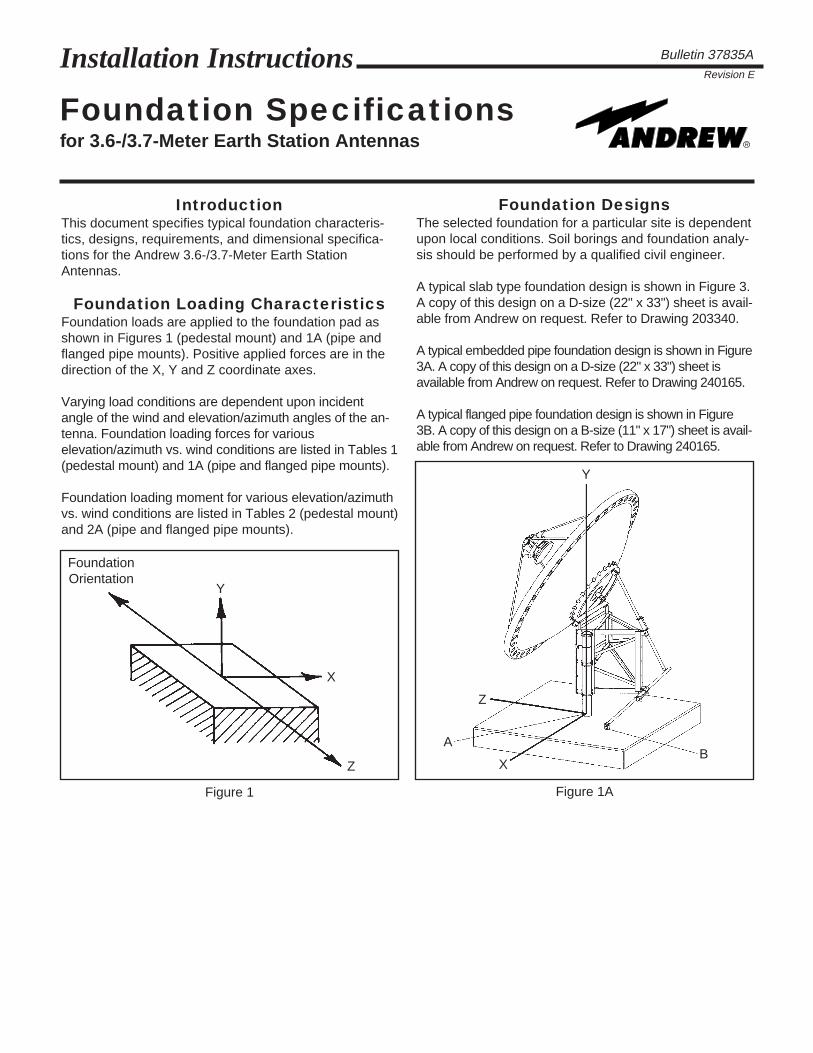
Foundation Loading CharacteristicsFoundation loads are applied to the foundation pad asshown in Figures 1 (pedestal mount) and 1A (pipe andflanged pipe mounts). Positive applied forces are in thedirection of the X, Y and Z coordinate axes.

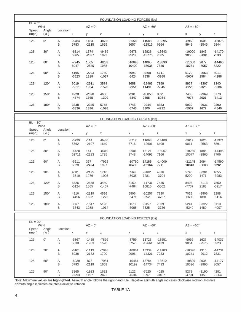
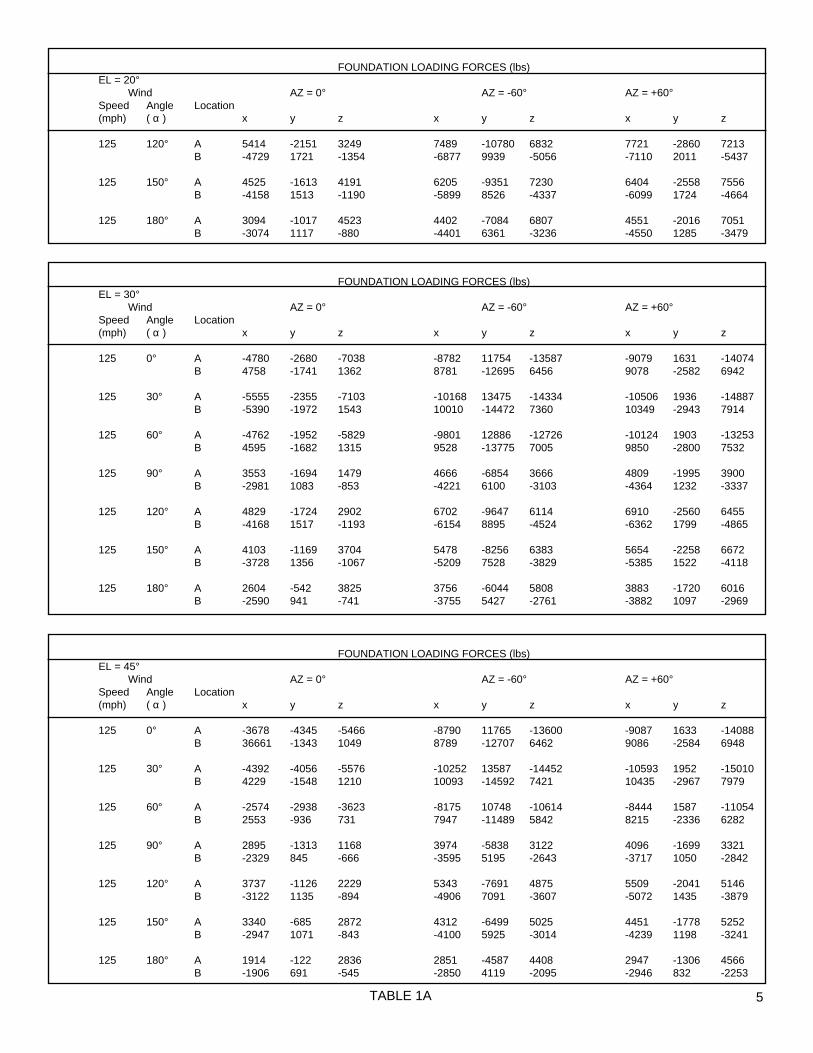
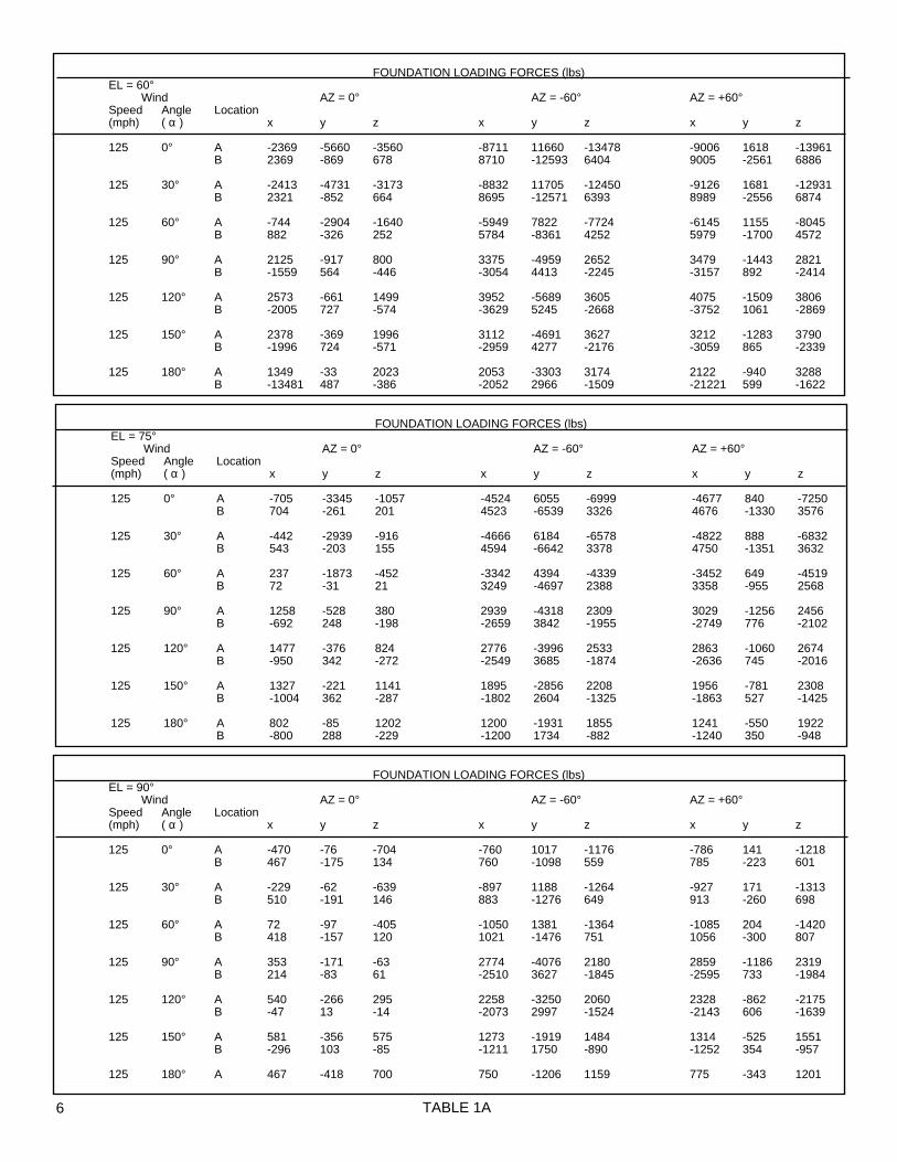
Varying load conditions are dependent upon incidentangle of the wind and elevation/azimuth angles of the an-tenna. Foundation loading forces for variouselevation/azimuth vs. wind conditions are listed in Tables 1(pedestal mount) and 1A (pipe and flanged pipe mounts).

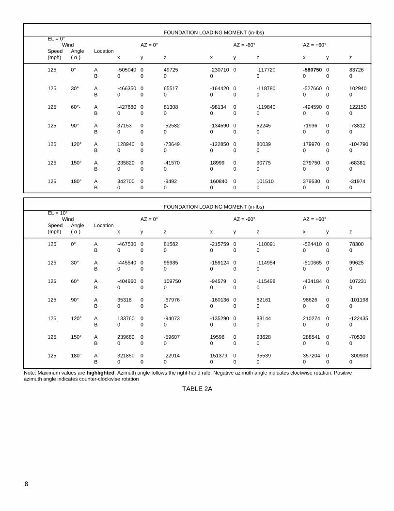
Foundation loading moment for various elevation/azimuthvs. wind conditions are listed in Tables 2 (pedestal mount)and 2A (pipe and flanged pipe mounts).

Foundation DesignsThe selected foundation for a particular site is dependentupon local conditions. Soil borings and foundation analy-sis should be performed by a qualified civil engineer.

A typical slab type foundation design is shown in Figure 3.A copy of this design on a D-size (22" x 33") sheet is avail-able from Andrew on request. Refer to Drawing 203340.

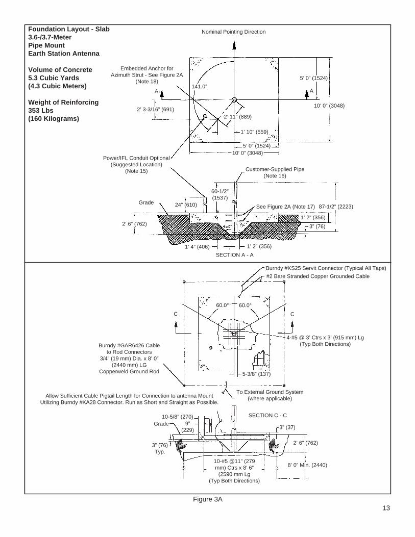
A typical embedded pipe foundation design is shown in Figure3A. A copy of this design on a D-size (22" x 33") sheet isavailable from Andrew on request. Refer to Drawing 240165.

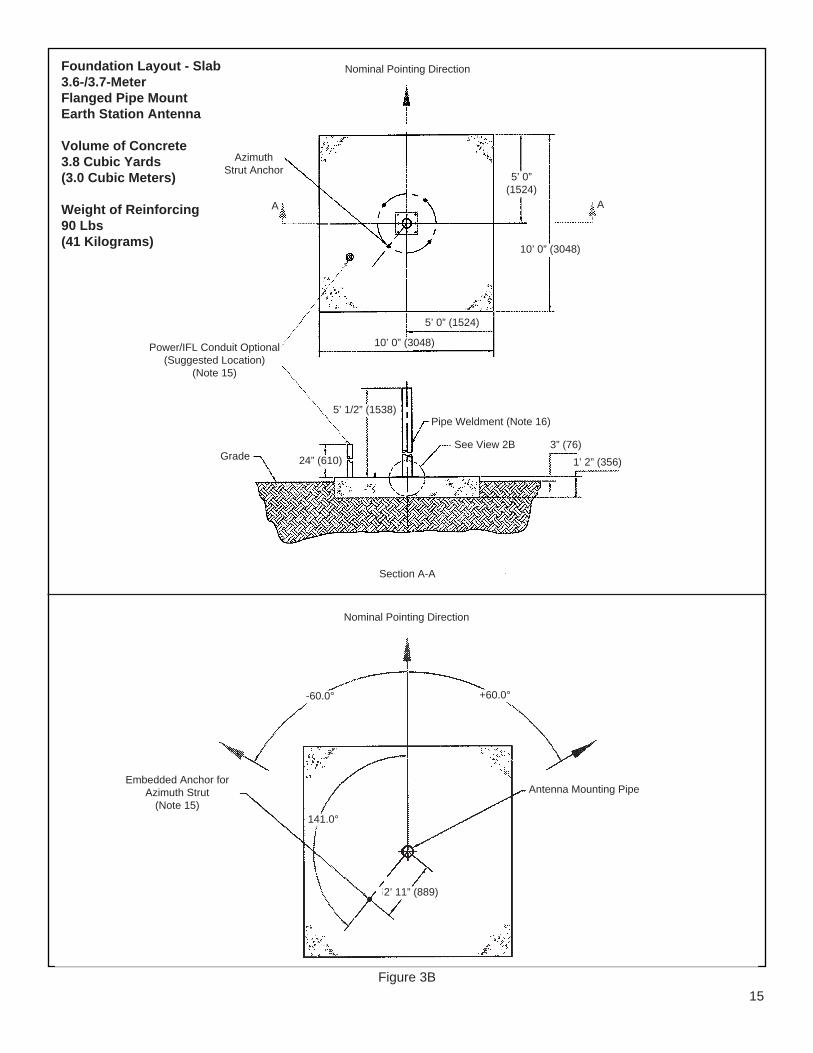
A typical flanged pipe foundation design is shown in Figure3B. A copy of this design on a B-size (11" x 17") sheet is avail-able from Andrew on request. Refer to Drawing 240165.

Figure 1

Y

X

Z

FoundationOrientation

Figure 1A

Z

A

XB

Y

Figure 2

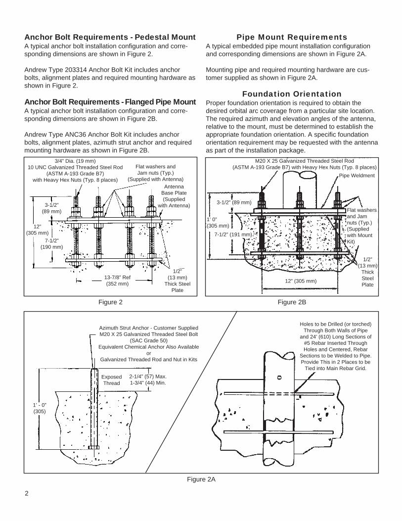
Pipe Mount RequirementsA typical embedded pipe mount installation configurationand corresponding dimensions are shown in Figure 2A.

Mounting pipe and required mounting hardware are cus-tomer supplied as shown in Figure 2A.

Foundation OrientationProper foundation orientation is required to obtain thedesired orbital arc coverage from a particular site location.The required azimuth and elevation angles of the antenna,relative to the mount, must be determined to establish theappropriate foundation orientation. A specific foundationorientation requirement may be requested with the antennaas part of the installation package.

1/2”(13 mm)

Thick SteelPlate

3/4” Dia. (19 mm)10 UNC Galvanized Threaded Steel Rod

(ASTM A-193 Grade B7)with Heavy Hex Nuts (Typ. 8 places)

Flat washers andJam nuts (Typ.)

(Supplied with Antenna)Antenna

Base Plate(Supplied

with Antenna)

13-7/8” Ref(352 mm)

7-1/2”(190 mm)

12”(305 mm)

3-1/2”(89 mm)

Figure 2A

2

Anchor Bolt Requirements - Pedestal MountA typical anchor bolt installation configuration and corre-sponding dimensions are shown in Figure 2.

Andrew Type 203314 Anchor Bolt Kit includes anchorbolts, alignment plates and required mounting hardware asshown in Figure 2.

Anchor Bolt Requirements - Flanged Pipe MountA typical anchor bolt installation configuration and corre-sponding dimensions are shown in Figure 2B.

Andrew Type ANC36 Anchor Bolt Kit includes anchorbolts, alignment plates, azimuth strut anchor and requiredmounting hardware as shown in Figure 2B.

Azimuth Strut Anchor - Customer SuppliedM20 X 25 Galvanized Threaded Steel Bolt

(SAC Grade 50)Equivalent Chemical Anchor Also Available

orGalvanized Threaded Rod and Nut in Kits

ExposedThread

2-1/4” (57) Max.1-3/4” (44) Min.

1’ - 0”(305)

Holes to be Drilled (or torched)Through Both Walls of Pipe

and 24’ (610) Long Sections of#5 Rebar Inserted ThroughHoles and Centered, Rebar

Sections to be Welded to Pipe.Provide This in 2 Places to be

Tied into Main Rebar Grid.

Figure 2B

1/2”(13 mm)

ThickSteelPlate

Pipe Weldment

Flat washersand Jamnuts (Typ.)(Suppliedwith MountKit)

12” (305 mm)

3-1/2” (89 mm)

7-1/2” (191 mm)

1’ 0”(305 mm)

M20 X 25 Galvanized Threaded Steel Rod(ASTM A-193 Grade B7) with Heavy Hex Nuts (Typ. 8 places)

FOUNDATION LOADING FORCES (lbs)EL = 30°

Wind AZ = 0° AZ = +60° AZ = -60°Speed Angle(mph) ( α ) x y z x y z x y z

125 30° 0 -5053 5760 -4988 -5053 2880 4988 -5053 2880

125 60° -406 -4289 5368 -4852 -4289 2332 4446 -4289 3036

125 -60° 406 -4289 5368 -4446 -4289 3036 4852 -4289 2332

125 135° -1136 -751 -2653 1730 -750 -2310 -2866 -751 -343

125 -135° 1136 -751 -2653 2866 -750 -343 -1730 -751 -2310

125 150° -1 -520 -3454 2991 -520 -1728 -2992 -520 -1726

FOUNDATION LOADING FORCES (lbs)EL = 60°

Wind AZ = 0° AZ = +60° AZ = -60°Speed Angle(mph) ( α ) x y z x y z x y z

125 ±60° 0 -6436 3431 -2972 -6436 1716 2972 -6436 1716

125 120° -4 -704 -2084 1803 -704 -1045 -1807 -704 -1039

125 -120° 4 -704 -2084 1807 -704 -1038 -1803 -704 -1045

FOUNDATION LOADING FORCES (lbs)EL = 90°

Wind AZ = 0° AZ = +60° AZ = -60°Speed Angle(mph) ( α ) x y z x y z x y z

125 90° Side Wind -1172 -821 -3.0 -583 -821 -1016 -589 -821 1014Frontal Wind 0 -821 1172 -1015 -821 586 1015 -821 586

125 -90° Side Wind 1172 -821 -3.0 589 -821 1014 583 -821 -1016Frontal Wind 0 -821 -1172 1015 -821 -586 -1015 -821 -586

FOUNDATION LOADING FORCES (lbs)EL = 0°

Wind AZ = 0° AZ = +60° AZ = -60°Speed Angle(mph) ( α ) x y z x y z x y z

125 0° 113 -1355 6682 -5730 -1355 3439 5843 -1355 3243

125 15° 216 -1355 6844 -5819 -1355 3609 6035 -1355 3235

125 -15° -216 -1355 6844 -6035 -1355 3235 5819 -1355 3609

125 30° 323 -1355 6837 -5760 -1355 3698 6083 -1355 3139

125 -30° -323 -1355 6837 -6083 -1355 3139 5760 -1355 3698

125 60° -431 -1355 6116 -5512 -1355 2685 5081 -1355 3431

125 -60° 431 -1355 6116 -5081 -1355 3431 5512 -1355 2685

125 135° -1391 -1355 -2600 1556 -1355 -2505 -2947 -1355 -95

125 -135° 1391 -1355 -2600 2947 -1355 -95 -1556 -1355 -2505

125 180° -41 -1355 -4155 -3619 -1355 2042 3578 -1355 2113

TABLE 1

3

FOUNDATION LOADING FORCES (lbs)EL = 0°

Wind AZ = 0° AZ = -60° AZ = +60°Speed Angle Location(mph) ( α ) x y z x y z x y z

125 0° A -5784 1183 -8686 -8658 11588 -13395 -8950 1608 -13875B 5783 -2115 1655 8657 -12515 6364 8949 -2545 6844

125 30° A -6514 1374 -8459 -9678 12826 -13643 -10000 1843 -14170B 6365 -2327 1822 9528 -13775 7005 9850 -2801 7533

125 60° A -7245 1565 -8233 -10698 14065 -13890 -11050 2077 -14466B 6947 -2540 1988 10400 -15035 7646 10751 -3057 8222

125 90° A 4195 -2293 1760 5995 -8808 4711 6179 -2563 5011B -3623 1318 -1037 -5424 7838 -3988 -5607 1584 -4288

125 120° A 6019 -2911 3574 8658 -12463 7899 8927 -3307 8340B -5311 1934 -1520 -7951 11491 -5845 -8220 2325 -6286

125 150° A 4928 -2628 4666 7201 -10853 8391 7433 -2969 8770B -4574 1665 -1309 -6847 9895 -5034 -7078 2001 -5413

125 180° A 3838 -2345 5758 5745 -9244 8883 5939 -2631 9200B -3836 1396 -1098 -5743 8300 -4222 -5937 1677 -4540

TABLE 1A

Note: Maximum values are highlighted . Azimuth angle follows the right-hand rule. Negative azimuth angle indicates clockwise rotation. Positiveazimuth angle indicates counter-clockwise rotation

FOUNDATION LOADING FORCES (lbs)EL = 10°

Wind AZ = 0° AZ = -60° AZ = +60°Speed Angle Location(mph) ( α ) x y z x y z x y z

125 0° A -5799 -114 -8436 -8717 11668 -13488 -9012 1620 -13971B 5762 -2107 1649 8716 -12601 6408 9011 -2563 6891

125 30° A -6428 144 -8310 -9901 13121 -13957 -10230 1885 -14496B 62711 -2293 1795 9748 -14092 7166 10077 -2865 7706

125 60° A -6911 357 -7928 -10790 14186 -14009 -11145 2094 -14590B 6628 -2424 1897 10489 -15164 7711 10843 -3083 8292

125 90° A 4081 -2125 1716 5569 -8182 4376 5740 -2381 4655B -3510 1276 -1005 -5038 7281 -3704 5209 1471 -3983

125 120° A 5826 -2558 3480 8150 -11731 7435 8403 -3113 7850B -5124 1865 -1467 -7484 10816 -5502 -7737 2188 -5917

125 150° A 4816 -2119 4536 6806 -10257 7930 7025 -2806 8288B -4456 1622 -1275 -6471 9352 -4757 -6690 1891 -5116

125 180° A 3567 -1647 5196 5070 -8157 7839 5241 -2322 8119B -3543 1288 -1014 -5068 7325 -3726 -5240 1480 -4007

FOUNDATION LOADING FORCES (lbs)EL = 20°

Wind AZ = 0° AZ = -60° AZ = +60°Speed Angle Location(mph) ( α ) x y z x y z x y z

125 0° A -5367 -1429 -7856 -8759 11723 -13551 -9055 1627 -14037B 5338 -1953 1528 8757 -12661 6439 9054 -2575 6923

125 30° A -6101 -1119 -7846 -10061 13334 -14183 -10396 1915 -14731B 5938 -2172 1700 9906 -14321 7283 10241 -2912 7831

125 60° A -6030 -878 -7081 -10484 13784 -13612 -10829 2035 -14177B 5793 -2119 1658 10192 -14734 7493 10536 -2995 8057

125 90° A 3865 -1923 1622 5122 -7525 4025 5279 -2190 4281B -3293 1197 -943 -4634 6697 -3407 -4791 1353 -3664

4

FOUNDATION LOADING FORCES (lbs)EL = 20°

Wind AZ = 0° AZ = -60° AZ = +60°Speed Angle Location(mph) ( α ) x y z x y z x y z

125 120° A 5414 -2151 3249 7489 -10780 6832 7721 -2860 7213B -4729 1721 -1354 -6877 9939 -5056 -7110 2011 -5437

125 150° A 4525 -1613 4191 6205 -9351 7230 6404 -2558 7556B -4158 1513 -1190 -5899 8526 -4337 -6099 1724 -4664

125 180° A 3094 -1017 4523 4402 -7084 6807 4551 -2016 7051B -3074 1117 -880 -4401 6361 -3236 -4550 1285 -3479

TABLE 1A

FOUNDATION LOADING FORCES (lbs)EL = 30°

Wind AZ = 0° AZ = -60° AZ = +60°Speed Angle Location(mph) ( α ) x y z x y z x y z

125 0° A -4780 -2680 -7038 -8782 11754 -13587 -9079 1631 -14074B 4758 -1741 1362 8781 -12695 6456 9078 -2582 6942

125 30° A -5555 -2355 -7103 -10168 13475 -14334 -10506 1936 -14887B -5390 -1972 1543 10010 -14472 7360 10349 -2943 7914

125 60° A -4762 -1952 -5829 -9801 12886 -12726 -10124 1903 -13253B 4595 -1682 1315 9528 -13775 7005 9850 -2800 7532

125 90° A 3553 -1694 1479 4666 -6854 3666 4809 -1995 3900B -2981 1083 -853 -4221 6100 -3103 -4364 1232 -3337

125 120° A 4829 -1724 2902 6702 -9647 6114 6910 -2560 6455B -4168 1517 -1193 -6154 8895 -4524 -6362 1799 -4865

125 150° A 4103 -1169 3704 5478 -8256 6383 5654 -2258 6672B -3728 1356 -1067 -5209 7528 -3829 -5385 1522 -4118

125 180° A 2604 -542 3825 3756 -6044 5808 3883 -1720 6016B -2590 941 -741 -3755 5427 -2761 -3882 1097 -2969

FOUNDATION LOADING FORCES (lbs)EL = 45°

Wind AZ = 0° AZ = -60° AZ = +60°Speed Angle Location(mph) ( α ) x y z x y z x y z

125 0° A -3678 -4345 -5466 -8790 11765 -13600 -9087 1633 -14088B 36661 -1343 1049 8789 -12707 6462 9086 -2584 6948

125 30° A -4392 -4056 -5576 -10252 13587 -14452 -10593 1952 -15010B 4229 -1548 1210 10093 -14592 7421 10435 -2967 7979

125 60° A -2574 -2938 -3623 -8175 10748 -10614 -8444 1587 -11054B 2553 -936 731 7947 -11489 5842 8215 -2336 6282

125 90° A 2895 -1313 1168 3974 -5838 3122 4096 -1699 3321B -2329 845 -666 -3595 5195 -2643 -3717 1050 -2842

125 120° A 3737 -1126 2229 5343 -7691 4875 5509 -2041 5146B -3122 1135 -894 -4906 7091 -3607 -5072 1435 -3879

125 150° A 3340 -685 2872 4312 -6499 5025 4451 -1778 5252B -2947 1071 -843 -4100 5925 -3014 -4239 1198 -3241

125 180° A 1914 -122 2836 2851 -4587 4408 2947 -1306 4566B -1906 691 -545 -2850 4119 -2095 -2946 832 -2253

5

FOUNDATION LOADING FORCES (lbs)EL = 60°

Wind AZ = 0° AZ = -60° AZ = +60°Speed Angle Location(mph) ( α ) x y z x y z x y z

125 0° A -2369 -5660 -3560 -8711 11660 -13478 -9006 1618 -13961B 2369 -869 678 8710 -12593 6404 9005 -2561 6886

125 30° A -2413 -4731 -3173 -8832 11705 -12450 -9126 1681 -12931B 2321 -852 664 8695 -12571 6393 8989 -2556 6874

125 60° A -744 -2904 -1640 -5949 7822 -7724 -6145 1155 -8045B 882 -326 252 5784 -8361 4252 5979 -1700 4572

125 90° A 2125 -917 800 3375 -4959 2652 3479 -1443 2821B -1559 564 -446 -3054 4413 -2245 -3157 892 -2414

125 120° A 2573 -661 1499 3952 -5689 3605 4075 -1509 3806B -2005 727 -574 -3629 5245 -2668 -3752 1061 -2869

125 150° A 2378 -369 1996 3112 -4691 3627 3212 -1283 3790B -1996 724 -571 -2959 4277 -2176 -3059 865 -2339

125 180° A 1349 -33 2023 2053 -3303 3174 2122 -940 3288B -13481 487 -386 -2052 2966 -1509 -21221 599 -1622

TABLE 1A

FOUNDATION LOADING FORCES (lbs)EL = 75°

Wind AZ = 0° AZ = -60° AZ = +60°Speed Angle Location(mph) ( α ) x y z x y z x y z

125 0° A -705 -3345 -1057 -4524 6055 -6999 -4677 840 -7250B 704 -261 201 4523 -6539 3326 4676 -1330 3576

125 30° A -442 -2939 -916 -4666 6184 -6578 -4822 888 -6832B 543 -203 155 4594 -6642 3378 4750 -1351 3632

125 60° A 237 -1873 -452 -3342 4394 -4339 -3452 649 -4519B 72 -31 21 3249 -4697 2388 3358 -955 2568

125 90° A 1258 -528 380 2939 -4318 2309 3029 -1256 2456B -692 248 -198 -2659 3842 -1955 -2749 776 -2102

125 120° A 1477 -376 824 2776 -3996 2533 2863 -1060 2674B -950 342 -272 -2549 3685 -1874 -2636 745 -2016

125 150° A 1327 -221 1141 1895 -2856 2208 1956 -781 2308B -1004 362 -287 -1802 2604 -1325 -1863 527 -1425

125 180° A 802 -85 1202 1200 -1931 1855 1241 -550 1922B -800 288 -229 -1200 1734 -882 -1240 350 -948

FOUNDATION LOADING FORCES (lbs)EL = 90°

Wind AZ = 0° AZ = -60° AZ = +60°Speed Angle Location(mph) ( α ) x y z x y z x y z

125 0° A -470 -76 -704 -760 1017 -1176 -786 141 -1218B 467 -175 134 760 -1098 559 785 -223 601

125 30° A -229 -62 -639 -897 1188 -1264 -927 171 -1313B 510 -191 146 883 -1276 649 913 -260 698

125 60° A 72 -97 -405 -1050 1381 -1364 -1085 204 -1420B 418 -157 120 1021 -1476 751 1056 -300 807

125 90° A 353 -171 -63 2774 -4076 2180 2859 -1186 2319B 214 -83 61 -2510 3627 -1845 -2595 733 -1984

125 120° A 540 -266 295 2258 -3250 2060 2328 -862 -2175B -47 13 -14 -2073 2997 -1524 -2143 606 -1639

125 150° A 581 -356 575 1273 -1919 1484 1314 -525 1551B -296 103 -85 -1211 1750 -890 -1252 354 -957

125 180° A 467 -418 700 750 -1206 1159 775 -343 1201

6

FOUNDATION LOADING MOMENT (in-lbs)EL = 0°

Wind AZ = 0° AZ = +60° AZ = -60°Speed Angle(mph) ( α ) x y z x y z x y z

125 0° 508145 -5288 -9062 261925 -5296 435517 246220 -5281 -444571

125 15° 521125 -24396 -17307 275546 -24397 442648 245579 -24391 -459955

125 -15° 521125 24396 17307 245579 24391 459955 275546 24397 -442648

125 30° 520564 -35277 -25880 282677 -35260 437920 237867 -35277 -463800

125 -30° 520564 35277 25880 237887 35277 463801 282677 35260 -437920

125 60° 462794 -40320 34534 201510 -40333 418049 261284 -40326 -383515

125 -60° 462794 40320 -34534 261284 40326 383515 201510 40333 -418049

125 135° -235576 119340 111454 -214338 119357 -148274 -21237 119349 259728

125 -135° -235576 -119340 -111454 -21237 -119349 -259728 -214338 -119357 148274

125 180° 305669 -1831 3285 149990 -1828 266373 155679 -1834 -263088

FOUNDATION LOADING MOMENT (in-lbs)EL= 30°

Wind AZ = 0° AZ = +60°` AZ = -60°Speed Angle(mph) ( α ) x y z x y z x y z

125 30° 369312 0 0 184653 -8 319808 184653 8 -319808

125 60° 359158 -35338 9393 171412 -35327 315753 187749 -35327 -306360

125 -60° 359158 35338 -9393 187749 35327 306360 171412 35327 -315753

125 135° -278406 77672 128208 -250197 77659 -177029 -28202 77669 305250

125 -135° -278406 -77672 -128208 -28194 -77669 -305237 -250205 -77669 177042

125 150° -363789 77 118 -182006 78 -315014 -181784 82 315135

FOUNDATION LOADING MOMENT (in-lbs)EL = 60°

Wind AZ = 0° AZ = +60° AZ = -60°Speed Angle(mph) ( α ) x y z x y z x y z

125 ±60° 179372 0 0 89728 -2 155403 89728 2 -155403

125 120° -253990 137 510 -127395 129 -219723 -126596 132 220232

125 -120° -253990 137 -510 -126501 -145 -220232 -127395 -129 219723

FOUNDATION LOADING MOMENT (in-lbs)EL = 90°

Wind AZ = 0° AZ = +60° AZ = -60°Speed Angle(mph) ( α ) x y z x y z x y z

125 90° Side Wind -399 -147 157683 -136713 -145 78458 136405 -146 79225Frontal Wind 157686 0 0 78848 -1 136566 78848 1 -136566

125 -90° Side Wind -399 -147 -157683 136405 146 -79225 -136713 145 -78458Frontal Wind -157686 0 0 -78845 1 -136561 -78845 -1 136561

TABLE 2

7

FOUNDATION LOADING MOMENT (in-lbs)EL = 0°

Wind AZ = 0° AZ = -60° AZ = +60°Speed Angle Location(mph) ( α ) x y z x y z x y z

125 0° A -505040 0 49725 -230710 0 -117720 -580750 0 83726B 0 0 0 0 0 0 0 0

125 30° A -466350 0 65517 -164420 0 -118780 -527660 0 102940B 0 0 0 0 0 0 0 0 0

125 60°- A -427680 0 81308 -98134 0 -119840 -494590 0 122150B 0 0 0 0 0 0 0 0 0

125 90° A 37153 0 -52582 -134590 0 52245 71936 0 -73812B 0 0 0 0 0 0 0 0 0

125 120° A 128940 0 -73649 -122850 0 80039 179970 0 -104790B 0 0 0 0 0 0 0 0 0

125 150° A 235820 0 -41570 18999 0 90775 279750 0 -68381B 0 0 0 0 0 0 0 0 0

125 180° A 342700 0 -9492 160840 0 101510 379530 0 -31974B 0 0 0 0 0 0 0 0 0

TABLE 2A

Note: Maximum values are highlighted . Azimuth angle follows the right-hand rule. Negative azimuth angle indicates clockwise rotation. Positiveazimuth angle indicates counter-clockwise rotation

FOUNDATION LOADING MOMENT (in-lbs)EL = 10°

Wind AZ = 0° AZ = -60° AZ = +60°Speed Angle Location(mph) ( α ) x y z x y z x y z

125 0° A -467530 0 81582 -215759 0 -110091 -524410 0 78300B 0 0 0 0 0 0 0 0 0

125 30° A -445540 0 95985 -159124 0 -114954 -510665 0 99625B 0 0 0 0 0 0 0 0 0

125 60° A -404960 0 109750 -94579 0 -115498 -434184 0 107231B 0 0 0 0 0 0 0 0 0

125 90° A 35318 0 -67976 -160136 0 62161 98626 0 -101198B 0 0 0- 0 0 0 0 0 0

125 120° A 133760 0 -94073 -135290 0 88144 210274 0 -122435B 0 0 0 0 0 0 0 0 0

125 150° A 239680 0 -59607 19596 0 93628 288541 0 -70530B 0 0 0 0 0 0 0 0 0

125 180° A 321850 0 -22914 151379 0 95539 357204 0 -300903B 0 0 0 0 0 0 0 0 0

8

FOUNDATION LOADING MOMENT (in-lbs)EL = 20°

Wind AZ = 0° AZ = -60° AZ = +60°Speed Angle Location(mph) ( α ) x y z x y z x y z

125 0° A -426440 0 104390 -199591 0 -101842 -485114 0 72433B 0 0 0 0 0 0 0 0 0

125 30° A -410910 0 123720 -149827 0 -108237 -480826 0 93803B 0 0 0 0 0 0 0 0 0

125 60° A -360610 0 126550 -86149 0 -105204 -434184 0 107231B 0 0 0 0 0 0 0 0 0

125 90°- A 32763 0 -81966 -1845207 0 71629 98626 0 -101198B 0 0 0 0 0 0 0 0 0

125 120° A 133820 0 -110420 -143536 0 93516 210274 0 -122435B 0 0 0 0 0 0 0 0 0

125 150° A 233320 0 -74999 19445 0 92906 286318 0 -69986B 0 0 0 0 0 0 0 0 0

125 180° A 295920 0 -30021 139544 0 88070 329278 0 -27740B 0 0 0 0 0 0 0 0 0

FOUNDATION LOADING MOMENT (in-lbs)EL = 30°

Wind AZ = 0° AZ = -60° AZ = +60°Speed Angle Location(mph) ( α ) x y z x y z x y z

125 0° A -375460 0 123200 -179645 0 -91664 -436634 0 65194B 0 0 0 0 0 0 0 0 0

125 30° A -364820 0 147450 -137383 0 -99248 -440893 0 86013B 0 0 0 0 0 0 0 0 0

125 60°- A -301450 0 128380 -86149 0 -105204 -434184 0 107231B 0 0 0 0 0 0 0 0 0

125 90°- A 29567 0 -94127 -184527 0 71629 98626 0 -101198B 0 0 0 0 0 0 0 0 0

125 120° A 129230 0 -121860 -143536 0 93516 210274 0 -122435B 0 0 0 0 0 0 0 0 0

125 150° A 220740 0 -86987 18825 0 89943 277186 0 -67754B 0 0 0 0 0 0 0 0 0

125 180° A 269640 0 -33315 127464 0 80446 300774 0 -25339B 0 0 0 0 0 0 0 0 0

FOUNDATION LOADING MOMENT (in-lbs)EL = 45°

Wind AZ = 0° AZ = -60° AZ = +60°Speed Angle Location(mph) ( α ) x y z x y z x y z

125 0° A -286800 0 143060 -145705 0 -74346 -354142 0 52877B 0 0 0 0 0 0 0 0 0

125 30° A -281830 0 172890 -115437 0 -83394 -370464 0 72273B 0 0 0 0 0 0 0 0 0

125 60° A -204160 0 100770 -86149 0 -105204 -434184 0 107231B 0 0 0 0 0 0 0 0 0

125 90° A 23294 0 -106910 -184527 0 71629 98626 0 -101198B 0 0 0 0 0 0 0 0 0

125 120° A 114580 0 -129000 -143536 0 93516 210274 0 -122435B 0 0 0 0 0 0 0 0 0

125 150° A 198430 0 -98644 17582 0 84005 258886 0 -63281B 0 0 0 0 0 0 0 0 0

125 180° A 234280 0 -32111 110941 0 700717 261783 0 -22054B 0 0 0 0 0 0 0 0 0

TABLE 2A 9

FOUNDATION LOADING MOMENT (in-lbs)EL = 60°

Wind AZ = 0° AZ = -60° AZ = +60°Speed Angle Location(mph) ( α ) x y z x y z x y z

125 0° A -184060 0 151710 -108437 0 -55330 -263561 0 39353B 0 0 0 0 0 0 0 0 0

125 30° A -172730 0 150310 -79944 0 -57753 -256556 0 50051B 0 0 0 0 0 0 0 0 0

125 60° A -117360 0 46361 -86149 0 -105204 -434184 0 107231B 0 0 0 0 0 0 0 0 0

125 90° A 16790 0 -114960 -184527 0 71629 98626 0 -101198B 0 0 0 0 0 0 0 0 0

125 120° A 94748 0 -126000 -143536 0 93516 210274 0 -122435B 0 0 0 0 0 0 0 0 0

125 150° A 169930 0 -97121 15529 0 74198 228662 0 -55893B 0 0 0 0 0 0 0 0 0

125 180° A 208300 0 -25056 98429 0 62121 232260 0 -19567B 0 0 0 0 0 0 0 0 0

TABLE 2A

FOUNDATION LOADING MOMENT (in-lbs)EL = 75°

Wind AZ = 0° AZ = -60° AZ = +60°Speed Angle Location(mph) ( α ) x y z x y z x y z

125 0° A -95687 0 77382 -55946 0 -28546 -135978 0 20303B 0 0 0 0 0 0 0 0 0

125 30° A -91063 0 47411 -35845 0 -25895 -115033 0 22442B 0 0 0 0 0 0 0 0 0

125 60° A -63040 0 -24074 -86149 0 -105204 -434184 0 107231B 0 0 0 0 0 0 0 0 0

125 90° A 9922 0 -116640 -184527 0 71629 98626 0 -101198B 0 0 0 0 0 0 0 0 0

125 120° A 74290 0 -115050 -143536 0 93516 210274 0 -122435B 0 0 0 0 0 0 0 0 0

125 150° A 128200 0 -78998 11948 0 57085 175925 0 -43002B 0 0 0 0 0 0 0 0 0

125 180° A 151240 0 -16230 71362 0 45038 168391 0 -14186B 0 0 0 0 0 0 0 0 0

FOUNDATION LOADING MOMENT (in-lbs)EL = 90°

Wind AZ = 0° AZ = -60° AZ = +60°Speed Angle Location(mph) ( α ) x y z x y z x y z

125 0° A -107270 0 2357 -48779 0 -24889 -118558 0 17702B 0 0 0 0 0 0 0 0 0

125 30° A -91762 0 -53530 -37091 0 -26795 -119032 0 23222B 0 0 0 0 0 0 0 0 0

125 60° A -51387 0 -95369 -86149 0 -105204 -434184 0 107231B 0 0 0 0 0 0 0 0 0

125 90° A 31521 0 -111850 -184527 0 71629 98626 0 -101198B 0 0 0 0 0 0 0 0 0

125 120° A 57259 0 -98745 -143536 0 93516 210274 0 -122435B 0 0 0 0 0 0 0 0 0

125 150° A 96453 0 -59299 8983 0 42922 132276 0 -32333B 0 0 0 0 0 0 0 0 0

125 180° A 110260 0 -4215 51766 0 32671 122152 0 -10291B 0 0 0 0 0 0 0 0 0

10

Figure 3

Nominal Pointing Direction

Burndy #KS25 Servit Connector(Typical All Taps)

#2 Bare Stranded CopperGrounded Cable

2’ 0” Min Typ(610 mm)

4’ 6”(1370 mm)

9’ 0”(2740 mm)

2-7/8”(73 mm)

Typ.

6-15/16”(176 mm)

Typ.2-7/8”(73 mm)

Typ.

6-15/16”(176 mm)

Typ.C 8-3/4” (19 mm) Dia.Anchor Bolts

(See Anchor Bolt Detail)

Burndy #GAR6426 Cableto Rod Connectors

3/4” (19 mm) Dia. x 8’ 0”(2440 mm) LG

Copperweld Ground Rod

4’ 6”(1370 mm)To External Ground System

(where applicable)

9’ 0”(2740 mm)

4-1/2”(114 mm)

Typ

3” Cir Typ(76 mm)

1’ 0”(305 mm)

3” Cir Typ(76 mm)

(Top and Bottom)

4’ 1/2”(1230 mm)

Typ

2-#5 @11” (279 mm) Ctrs x 4’ 0” (1220 mm Lg(Typ Both Directions)

Allow Sufficient Cable Pigtail Length forConnection to antenna Mount Utilizing Burndy#KA28 Connector. Run as Short and Straight

as Possible.

3” Approx(76 mm)

Grade

2’ 6” Min(762 mm)

8’ 0” Min(2440 mm)

10-#5 @11” (279 mm) Ctrs x 8’ 6” (2590 mm Lg(Typ Both Directions)

Section A-AScale: 1/2” = 1’

Foundation Layout - Slab3.6-/3.7-MeterPedestal MountEarth Station Antenna

Volume of Concrete3.0 Cubic Yards(2.3 Cubic Meters)

Weight of Reinforcing194 Lbs(88 Kilograms)

11

General Notes - Pedestal Mount

1. This foundation is a typical design only. Certification of its suitability for a particular installation by a professionalengineer is required prior to its use for actual fabrication.

2. All dimensions are shown in feet and inches (and millimeters).

3. Contractor shall field verify all dimensions locating existing construction before fabrication of new construction begins.

4. Concrete and related work shall be mixed, placed and cured in accordance with the "Building Code Requirements forReinforced Concrete" ACI 318-89 (Rev 88) and "Specifications for Structural Concrete" ACI 301-84 (Rev 88) PublicationSP-15 (88).

5. Concrete shall develop a compressive strength of at least 3000 psi (211 kgf/cm2) in 28 days with a maximum slump of3" (76 mm) at time of placing.

6. Reinforcing bars shall conform to ASTM A615 (S1) grade 60 deformed type Fy = 60,000 psi (4,220 kgf/cm2).

7. Unless otherwise noted, concrete cover for reinforcing bars shall conform to the minimum requirements of ACI 318-89(Rev 88).

8. Fabrication of reinforcing steel shall be in accordance with the "Manual of Standard Practice for Detailing ReinforcedConcrete Structures" ACI 315-80 (Rev 86).

9. Provide 3/4" (19 mm) x 45° chamfer on all exposed concrete edges.

10. Foundations have been designed to rest on undisturbed soil (per EIA-411-A and RS-222-E) with a minimum allowablenet vertical bearing capacity of 2000 psf (9770 kgf/m2). If undesirable soil conditions are encountered, the engineer shallbe notified.

11. Backfills shall be suitable excavated material or other suitable material compacted in 3" (76 mm) lifts to 90% of maxi-mum density as determined by ASTM D1557.

12. Ground rods shall be driven to depths as shown (below permanent moisture level) and ground system resistancemeasured. The antenna structure shall be connected to a grounding system consisting of a number of interconnectedground rods. The system shall meet the standards of the Underwriters' Laboratories Publication No. UL96A for lightningprotection. The ground rod system-to-earth resistance shall not exceed 10 Ohms at any time during the year.

13. Grounding system shown is the minimum necessary. Local conditions will dictate grounding system design.

14. If this foundation is to be located in an area where the annual frost penetration depth exceeds 9" (229 mm), the localbuilding code specifying a minimum required foundation depth should be consulted.

12

Figure 3A

Foundation Layout - Slab3.6-/3.7-MeterPipe MountEarth Station Antenna

Volume of Concrete5.3 Cubic Yards(4.3 Cubic Meters)

Weight of Reinforcing353 Lbs(160 Kilograms)

Nominal Pointing Direction

Burndy #KS25 Servit Connector (Typical All Taps)

#2 Bare Stranded Copper Grounded Cable

141.0”

5’ 0” (1524)

10’ 0” (3048)

1’ 10” (559)

5’ 0” (1524)10’ 0” (3048)

2’ 3-3/16” (691)2’ 11” (889)

Embedded Anchor forAzimuth Strut - See Figure 2A

(Note 18)

A A

Power/IFL Conduit Optional(Suggested Location)

(Note 15) Customer-Supplied Pipe(Note 16)

60-1/2”(1537)

24” (610)

2’ 6” (762)

Grade

1’ 4” (406) 1’ 2” (356)

SECTION A - A

87-1/2” (2223)

1’ 2” (356)

3” (76)

See Figure 2A (Note 17)

SECTION C - C

C C

60.0° 60.0°

5-3/8” (137)

Burndy #GAR6426 Cableto Rod Connectors

3/4” (19 mm) Dia. x 8’ 0”(2440 mm) LG

Copperweld Ground Rod

To External Ground System(where applicable)Allow Sufficient Cable Pigtail Length for Connection to antenna Mount

Utilizing Burndy #KA28 Connector. Run as Short and Straight as Possible.

3” (37)

10-5/8” (270)Grade 9”

(229)

3” (76)Typ.

2’ 6” (762)

10-#5 @11” (279mm) Ctrs x 8’ 6”

(2590 mm Lg(Typ Both Directions)

8’ 0” Min. (2440)

4-#5 @ 3’ Ctrs x 3’ (915 mm) Lg(Typ Both Directions)

13

General Notes - Pipe Mount

1) This foundation is a typical design only. Certification of its suitability for a particular installation by a professional engi-neer is required prior to its use for actual fabrication.

2) All dimensions are shown in feet and inches (and millimeters).

3) Contractor shall field verify all dimensions locating existing construction before fabrication of new construction begins.

4) Concrete and related work shall be mixed, placed and cured in accordance with the “Building Code Requirements forReinforced Concrete” ACI 318-89 and “Specifications for Structural Concrete” ACI 301-84 Publication SP-15.

5) Concrete shall develop a compressive strength of at least 3000 psi (211 kgf/cm sq) in 28 days with a maximum slumpof 3” (76 mm) at the time of placing.

6) Reinforcing bars shall conform to ASTM A-615 (51) Grade 60 deformed type fy = 60,000 psi (4,220 kgf/cm sq)

7) Unless otherwise noted, concrete cover for reinforcing bars shall conform to the minimum requirements of ACI 315-80.

8) Fabrication of reinforcing steel shall be in accordance with the “Manual of Standard Practice for Detailing ReinforcedConcrete Structures” ACI 315-74.

9) Provide 3/4” (19mm) x 45° chamfer on all exposed concrete edges.

10) Foundations have been designed) to rest on undisturbed soil vith a minimum allowable bearing capacity of 2000 psf(9770 kgf/m sq). If undesirable soil conditions are encountered, the engineer shall be notified.

11) Backfills shall be suitable excavated material or other suitable material compacted in 3” (76 mm) lifts to 90% of maxi-mum density as determined by ASTM D1557.

12) Ground rods shall be driven to depths as shown (below permanent moisture level) and ground system resistancemeasured. The antenna structure shall be connected to a grounding system consisting of a number of interconnectedground rods. The system shall meet the standards of the Underwriters’ Laboratories Publication no. UL96A for lightningprotection. The ground rod system-to-earth resistance shall not exceed 1.0 Ohm at any time during the year.

13) Grounding system shown is the minimum necessary. Local conditions will dictate grounding system design.

14) If this foundation is to be located in an area where the annual frost penetration depth exceeds 9” (229 mm) the localbuilding code specifying a minimum required foundation depth should he consulted.

15) Electrical/IFL power - Drawing depicts suggested location for electrical power conduit to antenna. Size, type anddepth to bury conduit to be determined by customer in compliance with local codes. Direction to route conduit to be deter-mined by the relative location of communications building/shelter. Power conduit to extend 6” (minimum) above surface offoundation slab. Open ends of conduit to be sealed to prevent moisture and foreign particle contamination.

16) Customer-supplied pipe:6” (152) nominal schedule 80 steel pipe per ASTM A53, Grade B, Type E, or equivalent (actual O.D. 6-5/8” (168),0.28” (7.1) wall thickness), 87-1/2” (2223 long, hot dip galvanized per ASTM A123. Pipe must be filled with con-crete for additional stiffness.

17) Holes to be drilled (or torched) through both walls of pipe and 24’ (610) long sections of #5 rebar inserted throughholes and centered, rebar sections to be welded to pipe. Provide this in 2 places to be tied into main rebar grid.

18) The position shown for the embedded azimuth strut anchor will provide of azimuth travel in ±7.5° sections from thenominal antenna pointing direction. Additional anchors can be embedded to accomodate additional nominal antennapointing directions.

14

15Figure 3B

Nominal Pointing Direction

Nominal Pointing Direction

AzimuthStrut Anchor

Power/IFL Conduit Optional(Suggested Location)

(Note 15)

5’ 0”(1524)

5’ 0” (1524)

10’ 0” (3048)

10’ 0” (3048)

AA

Section A-A

Pipe Weldment (Note 16)

See View 2B 3” (76)

1’ 2” (356)

5’ 1/2” (1538)

24” (610)Grade

Embedded Anchor forAzimuth Strut

(Note 15)

Antenna Mounting Pipe

+60.0°-60.0°

141.0°

2’ 11” (889)

Foundation Layout - Slab3.6-/3.7-MeterFlanged Pipe MountEarth Station Antenna

Volume of Concrete3.8 Cubic Yards(3.0 Cubic Meters)

Weight of Reinforcing90 Lbs(41 Kilograms)

16

General Notes - Flanged Pipe Mount

1) This foundation is a typical design only. Certification of its suitability for a particular installation by a professional engi-neer is required prior to its use for actual fabrication.

2) All dimensions are shown in feet and inches (and millimeters).

3) Contractor shall field verify all dimensions locating existing construction before fabrication of new construction begins.

4) Concrete and related work shall be mixed, placed and cured in accordance with the “Building Code Requirements forReinforced Concrete” ACI 318-89 and “Specifications for Structural Concrete” ACI 301-84 Publication SP-15.

5) Concrete shall develop a compressive strength of at least 3000 psi (211 kgf/cm sq) in 28 days with a maximum slumpof 3” (76 mm) at the time of placing.

6) Reinforcing bars shall conform to ASTM A-615 (51) Grade 60 deformed type fy = 60,000 psi (4,220 kgf/cm sq)

7) Unless otherwise noted, concrete cover for reinforcing bars shall conform to the minimum requirements of ACI 315-80.

8) Fabrication of reinforcing steel shall be in accordance with the “Manual of Standard Practice for Detailing ReinforcedConcrete Structures” ACI 315-74.

9) Provide 3/4” (19mm) x 45° chamfer on all exposed concrete edges.

10) Foundations have been designed) to rest on undisturbed soil vith a minimum allowable bearing capacity of 2000 psf(9770 kgf/m sq). If undesirable soil conditions are encountered, the engineer shall be notified.

11) Backfills shall be suitable excavated material or other suitable material compacted in 3” (76 mm) lifts to 90% of maxi-mum density as determined by ASTM D1557.

12) Ground rods shall be driven to depths as shown (below permanent moisture level) and ground system resistancemeasured. The antenna structure shall be connected to a grounding system consisting of a number of interconnectedground rods. The system shall meet the standards of the Underwriters’ Laboratories Publication no. UL96A for lightningprotection. The ground rod system-to-earth resistance shall not exceed 1.0 Ohm at any time during the year.

13) Grounding system shown is the minimum necessary. Local conditions will dictate grounding system design.

14) If this foundation is to be located in an area where the annual frost penetration depth exceeds 9” (229 mm) the localbuilding code specifying a minimum required foundation depth should he consulted.

15) Electrical/IFL power - Drawing depicts suggested location for electrical power conduit to antenna. Size, type anddepth to bury conduit to be determined by customer in compliance with local codes. Direction to route conduit to be deter-mined by the relative location of communications building/shelter. Power conduit to extend 6” (minimum) above surface offoundation slab. Open ends of conduit to be sealed to prevent moisture and foreign particle contamination.

16) Customer-supplied pipe:6” (152) nominal schedule 80 steel pipe per ASTM A53, Grade B, Type E, or equivalent (actual O.D. 6-5/8” (168),0.28” (7.1) wall thickness), 87-1/2” (2223 long, hot dip galvanized per ASTM A123. Pipe must be filled with con-crete for additional stiffness.

17) Holes to be drilled (or torched) through both walls of pipe and 24’ (610) long sections of #5 rebar inserted throughholes and centered, rebar sections to be welded to pipe. Provide this in 2 places to be tied into main rebar grid.

18) The position shown for the embedded azimuth strut anchor will provide of azimuth travel in ±7.5° sections from thenominal antenna pointing direction. Additional anchors can be embedded to accomodate additional nominal antennapointing directions.

Antenna GeometryBasic dimensional characteristics and azimuth adjustmentrange capabilities are shown in Figures 4, 4A, 5 and 5A.

Figure 6, 7 and 8 illustrate varying dimensions from groundreference of selected antenna points as the elevation anglefluctuates from 0° to 90°.

Figure 4

6.1 ft(1.86 m)

12.2 ft(3.7 m)

3.8 ft(1.2 m)

8.8 ft max.(2.7 m)

TopView

Panning FrameCenter Line

7.2 ft(2.2 m)

3.6-MeterEarth Station Antenna

(Pedestal Mount)

17

Figure 4A

3.6 ft(1.1 m)

3.6 ft(1.1 m)

6.8 ft(2.1 m) 8.6 ft

(2.6 m)

4.0 ft(1.2 m)

3.2 ft(1 m)

10.0 ft(3.0 m)

4.0 ft(1.2 m)

10.0 ft(3.0 m)

8.0 ft(2.4 m)

3.6-/3.7-MeterEarth Station Antenna

(Pipe Mount)Top View

18

Figure 5

LeftPosition

(-90° to +30°)

CenterPosition

(-60° to +60°)

RightPosition

(-30° to +90°)

TopView

Panning FrameCenter Line

3.7-MeterEarth Station Antenna

(Pedestal Mount)

6.1 ft(1.86 m)

12.2 ft(3.7 m)

5.8 ft(1.8 m)

8.5 ft(2.6 m)

8.8 ft max.(2.7 m)

19

Figure 5A

2.5 ft(.75 m)

2.3 ft(.69 m)

3.25 ft(.975 m)

7.87 ft(2.36 m)

1.7 ft(.5 m)5.0 ft

(1.5 m)

.74 ft (.22 m)

.8 ft (.24 m)

1.5 ft(.45 m)

12 ft(3.6 m)

3.6-/3.7-MeterEarth Station Antenna

(Pipe Mount) Side View

20

Figure 6

D

C

B

A

E’

EL°

Side View

3.6-MeterEarth Station Antenna

(Pedestal Mount)

A = Lower Rim HeightB = Vertex Center HeightC = Subreflector Strut

Tip HeightD = Upper Rim HeightE’ = Rim ExtensionEL = Elevation Angle

Figure 7

D

C

B

A

E

EL°

Side View

A = Lower Rim HeightB = Vertex Center HeightC = Subreflector Strut

Tip HeightD = Upper Rim HeightE = Rim ExtensionEL = Elevation Angle

3.7-MeterEarth Station Antenna

(Pedestal Mount)

21

Andrew Corporation10500 West 153rd StreetOrland Park, IL U.S.A. 60462

Telephone: 708/349-3300FAX (U.S.A.): 1-800/349-5444

Customer Service, 24 hours: U.S.A. • Canada • Mexico: 1-800/255-1479U.K.: 0800 250055 • Republic of Ireland: 1 800 535358Other Europe: +44 1592 782612

Printed in U.S.A. 4/99

Copyright © 1999 by Andrew Corporation

Figure 8

Dimension (Meters)

Dimension (Feet)

Ele

vatio

n A

ngle

(D

egre

es)

B

A

E’

E

CD


Recommended